
Submitted:
05 November 2024
Posted:
06 November 2024
You are already at the latest version
Abstract
In today’s expanding cities, pipeline networks are becoming an essential part of the industrial infrastructure. Monitoring these pipelines autonomously is becoming increasingly important. Inspecting pipelines for cracks is one specific task that poses a huge burden on humans. Undetected cracks may pose multi-dimensional risks. In this paper, we introduce the Pipeline Leak Identification Emergency Robot Swarm (PLIERS) system; an industrial system that deploys Internet of Things (IoT), robotics, and Neural Network technologies to detect cracks in emptied water and sewage pipelines. In PLIERS, a swarm of robots inspect emptied pipelines from the inside to detect cracks, collect images of them, and register their locations. When the images are taken, they are fed into a cloud-based module for analysis by a convolutional neural network (CNN). CNN is used to detect cracks and identify their severity. Through extensive training and testing, the CNN model performance showed promising scores for accuracy (between 80% and 90%), recall (at least 95%), precision (at least 95%), and F1 (at least 96%). Additionally, through the careful design of a prototype for a water/sewage pipeline structure with several types of cracks, the robots used managed to exchange information among themselves and convey crack images to the cloud-based server for further analysis. PLIERS is a system that deploys trendy technologies to detect and recognize cracks in pipeline grids. It adds to the efforts of improving instrumentation and measurement approaches by using robots, sensory, IoT principles, and the efficient analysis of CNN’s.
Keywords:
Automation
; Internet of Things
; Machine Learning
; Convolutional Neural Network
; Industrial Application
; Pipeline Crack Detection
1. Introduction
The worldwide population is increasing at a very rapid rate, and with it comes the need for the continuous expansion of cities as well as an exponentially increased demand for industrial factories, sewage systems, and power stations. These vast factories and stations require to be autonomously maintained. However, the standard ways of maintaining their extensive pipeline networks are all done manually, which is becoming costly and risky. A study by Koch et al. [1] showed that in the United States, the cost of corrosion is approximately $276 billion per year, which calculates to be 3.1 percent of their GDP. Furthermore, cracks in pipelines cause several types of issues, including posing a danger to workers, causing environmental damage, and damaging goods. Endangering workers is especially important, as it can occur in two different ways. First, workers can develop serious long-term health issues, such as respiratory problems, caused by the inhalation of toxic gases present in the pipelines being inspected. Second, workers are also at risk of injuries and fatalities caused by the failures (due to bursts or explosions) of pipelines. A recent example of this is a gas explosion in Brimingham, England [2] caused by gas escaping from the pipelines, which lead to deaths, injuries, and the destruction of houses. Additionally, cracked pipelines may lead to damage to the industrial infrastructure, which poses financial burdens on governments and industries. Nowadays, factories cover more and more areas and have a huge infrastructure that makes it hard to examine its pipeline structure by humans. Therefore, automated robots play an important role in identifying any cracks or damages.
Robots can minimize the time needed to examine such a huge structure and allow humans to use the time to fix the cracks instead. In addition to saving time, autonomous robots can save human lives when finding a crack in such dangerous areas, such as gas and oil factories, which could be life-threatening if inspected by a human. This is where Pipeline Leak Identification Emergency Robot Swarm (PLIERS) comes into play. PLIERS utilizes robots to autonomously traverse complex pipeline networks. These robots will first detect potential cracks using ultrasonic sensors. If a potential crack is found, the location is communicated to the control station and the other robots, then the crack is verified and its severity is assessed by taking an image with an onboard camera and passing it to the control station to process it with a convolutional neural network (CNN) model. Note that there are two main assumptions being made about the system of pipes PLIERS is intended to be used in. First, PLIERS is intended to be used in empty pipeline networks while they are out of service. This is because repairing and/or replacing damaged pipes would already require the pipeline system to be emptied and out of service. Second, the developed PLIERS system is assumed to operate within horizontal pipeline systems only for the sake of simplicity. While this is not always the case in actual pipeline systems across the world, the main priority of PLIERS is the crack detection and identification, which traversing vertical pipes would have taken focus away from. Despite this, the traversal of vertical pipes is definitely a future step in the development of PLIERS.
This work is an extension of the work reported in [3]. Our contributions in this paper are as follows:
- We have built a novel system, PLIERS, for detecting cracks in pipelines that leverages IoT and machine learning technologies. The solution deploys a swarm of robots to navigate and detect cracks. To the limit of our search, this is the first work that detects pipeline cracks by relying on a swarm of robots.
- We have developed a unique dataset of 4200 labeled images for pipeline cracks. To the limit of our search, no similar dataset is available. The availability of this dataset enables more rigorous testing and evaluation of the PLIERS system.
The rest of the paper is organized as follows: Section II discusses the many proposals put forth to solve the issue of pipeline crack inspection in existing literature. Section III describes the system model of PLIERS. Section IV provides the details of the implementation of PLIERS. Next, Section V tests and evaluates the operation of PLIERS. Finally, Section VII draws future directions for PLIERS before Section VIII concludes this paper.
2. Literature Survey
Clearly, assuring the quality of the installed pipelines and maintaining them for long periods is essential for economical, societal, and environmental purposes. These facts are motivating research efforts to devise efficient solutions for pipeline health inspections. The research community has contributed many proposals in that direction. These proposals deployed approaches like magnetic field leakage testing, eddy current testing, stress wave propagation testing, and image-based testing. In this section, we will discuss each proposal and see how they compare with PLIERS.
In [4], Shukla et al. introduce a navigation system that uses an Unmanned Aerial Vehicle (UAV), equipped with cameras, to capture a pipeline’s structure by flying at a very low altitude. This system, however, inspects pipes and does not perform crack detection. In comparison with PLIERS, our robots inspect the emptied water/sewage pipelines from the inside by detecting cracks using ultrasonic sensors, capturing crack images and categorizing their severity using a CNN model. Furthermore, in contrast to Shukla’s system, which relies on human interaction by controlling the UAV and looking at the live video to detect cracks, PLIERS is autonomous with no human interaction needed during the process of crack detection.
In [5], Le et al. propose an inspection robot that scans underground pipes for cracks using multiple sensors. The system is supported by a central data processing machine that verifies the detected flaws. On the downside, this system is designed for straight pipes and the use of multiple sensors can interfere with the scanning signals. When comparing these aspects to PLIERS, our proposed system is composed of a swarm of robots that are placed at different endpoints of the pipeline structure, and then each robot follows a preset path which allows them to scan any horizontal pipeline structure. The scanning signal is not interfered with here since PLIERS only uses one type of sensor which is the ultrasonic sensor (for obstacle avoidance). More details on these aspects will be elaborated on in Section IV.
A similar system by Mohammed et al. in [6] inspects pipelines for cracks and corrosion using a robot with ultrasonic sensors and an IP camera. However, the control of the robot and the identification of crack severity are human-based. In contrast, our swarm of robots are autonomous once they are fed the preset paths and use our CNN model to detect the cracks and categorize them with minimal human interactions.
Waleed et al. presented a different system that consists of an in-pipe inspection robot used to detect leaks in oil, gas, and sewage pipelines using pressure sensors [7]. It works by having the robot collect data using three barometric pressure sensors to be analyzed using an Artificial Neural Network before sending the data wirelessly to an operator. While this system can detect leaks, it does not locate them, and is unable to detect cracks in the absence of a leak. On the other hand, PLIERS can detect cracks regardless of whether there is a leak or not because it depends on the crack recognition of the CNN model. The robots scan the entire pipeline structure autonomously using the preset map. More on this will be elaborated in Section III of the paper. Finally, while PLIERS is only intended for water/sewage pipeline structures for now, it can be further modified and implemented for the oil and gas sector.
Yuan et al. [8] used a bobbin coil with tunnel magnetoresistance (TMR) sensor arrays fitted inside a probe and a module that emits sinusoidal waves. The waves emitted send a current through the tube’s material, which is detected by the probe inserted inside the tube. The current goes through the inner wall of the pipe, and if there is a crack, the density of the current will be affected. The main disadvantage of this system is that it requires the distance between the bobbin coil and the inner wall to be as small as possible for the best results. In PLIERS, robots are designed to scan the emptied pipes from the inside. Each robot is fitted with two cameras, each with an LED, and three ultrasonic sensors (two for crack detection, and one for obstacle avoidance). This makes the design of the robots flexible and can be controlled to have a more accurate reading. The robots were tested using two different pipe types, High-Density Polyethylene (HDPE) and Polyvinyl Chloride (PVC). Both materials allowed the system to work. Our system’s testing results will be further discussed in Section V of this paper.
Norli et al. used ultrasonic waves to detect stress corrosion cracking in a controlled environment [9]. The ultrasonic waves are detected using a custom-made scanner containing gas, transmitting, and receiving transducers. The waves bounce towards the receiving transducers to record the data for analysis. The latter can show defected locations, defect sizes, wall thickness, spectral power, and other surface irregularities. This system was built in a controlled environment and thus they did not mention how it performs in the real world where the environment plays an important role, especially when it comes to the curved nature of the pipes. PLIERS has been tested in environments that resemble real-life scenarios which is why we were able to discover limitations that come with ultrasonic sensors and fully test our CNN algorithm to confirm and categorize the detected cracks.
F. Nickols et al. aimed to eliminate the need for an umbilical in-pipe inspection device by building an inspection submarine that operates in a water-filled pipe, independent of an umbilical [10]. Umbilically-controlled systems increase overall cost and limit the maneuverability of the robot. PLIERS aims to achieve such results where the robots are autonomous and wireless, however due to the unavailability of convenient submarine options, PLIERS relies on a system of wheels for movement. The submarine designed in the mentioned paper does not account for obstacle avoidance and has not been tested. In contrast, PLIERS has been tested for both its movement in horizontal pipeline systems and its obstacle avoidance capabilities.
In [11], Du et al. conducted an active-sensing approach to identify cracks using stress wave propagation with piezoceramic transducers. This approach, however, is susceptible to environmental noise, cannot be applied to buried pipes, and is costly. PLIERS, on the other hand, is aimed at underground water/sewage pipelines. In order for our robots to work, the pipeline structure will need to be emptied out.
Finally, Dai et al. proposed an embedded eddy current testing system by leveraging image processing and neural networks [12]. The problem with this system is that it is limited to girth weld defects. In contrast, PLIERS focuses on pipe material typical in water/sewage pipeline structures.
3. System Model
This section describes the system model of PLIERS, specifically its design requirements and method of operation.
3.1. Design Requirements
In light of the literature review and our understanding of the problem, we can define a set of fundamental functional requirements that we target in the design of PLIERS. These requirements are summarized as follows:
- Automate the scanning of pipelines for detecting cracks using a swarm of robots.
- Equip robots with a pair of ultrasonic sensors and cameras to identify cracks and take pictures of them.
- Scan pipelines of any shape in the horizontal orientation.
- Equip robots with gyroscopes for self-balance.
- Equip robots with ultrasonic sensors for obstacle avoidance, including accumulation of rust, dirt, severe cracks, etc.
- Identify both the crack severity and the crack location.
- Employ a Convolutional Neural Network (CNN) for crack severity classification.
To the extent of our knowledge, these requirements have not been supported collectively in any of the solutions we found in the literature. To address this, we propose designing PLIERS as an Internet of Things (IoT) system that is composed of four main pillars:
- Data collection: data about cracks is collected using cameras mounted on the robots.
- Connectivity: robot-to-robot communication is realized using the low power and long range LoRa technology, while robot-to-server communication is realized using both LoRa and Wi-Fi technologies. LoRa is utilized for sending information about the crack while Wi-Fi is used to send images of suspected cracks to the server.
- Cloud server: a control center that implements a CNN model to analyze the data sent by robots and extract information about the cracks to store them locally.
- Database: a database with an appropriate user interface to check the crack information which includes the crack image, location, severity, and ID of the robot that detected it.
The system model of PLIERS is illustrated in Figure 1. The next section describes the method of operation of PLIERS.
3.2. Method of Operations
This section explains the operation of PLIERS from the perspective of the robot enclosed in the red box. Our method of operation is divided into three stages: Pipeline Structure Preparation and Mapping, Robots Operations, and Results Observation.
3.2.1. Piepline Structure Preparation and Mapping
The first step in the PLIERS operation involves preparing and mapping the pipeline before the robots become operational. As the system is designed for underground water/sewage pipelines, the structure will need to be emptied out for inspection. The pipeline structure will also need to be studied and a map is prepared for the robots to follow. In its initial stages, PLIERS depends on present maps, meaning the robots are not able to navigate the pipeline system on their own. Instead, a map of the pipeline system is prepared and divided amongst the robots so each robot has a specific path to follow to avoid any collisions between them. In case of obstacles, robots are supposed to report back to the server, then go back to the path they initially came from. Each robot will be programmed to follow a different path, with all the turns and moves provided in the code so that collaboratively, all robots cover the entire system in an efficient way.
3.2.2. Robots Operation
Once the swarm of robots are placed inside the pipeline structure, the operator then initiates the scan from the application at the control center. Both the control center and the camera module on each robot must be connected to the same Wi-Fi network for the robot-to-server communication to work. At this stage, the robots and the control station are ready to communicate using both Wi-Fi and LoRa. Wi- Fi for the server to receive pictures of the suspected cracks from the robots, and LoRa for receiving information related to the image like its location and robot ID. Afterward, the robots start to automatically scan the pipelines for cracks using the preset map while self-balancing themselves using a gyroscope. This way of navigation inside the pipeline structure offers a more dynamic system as the map can be customized based on different pipeline structures, a feature that was not touched upon in the literature that we reviewed. The robot begins inside the pipeline at coordinates (0 cm, 0 cm) and assesses its ability to move forward using the ultrasound sensor. It navigates obstacles by attempting right or left turns, or by moving backward if neither are possible. Once it can move forward, it checks its balance using the gyroscope and adjusts its movement accordingly, then travels 10 cm along the set path before updating its coordinates. For every 10 cm travelled, each robot scans for cracks using ultrasonic sensors. Upon detecting a new crack, the robot captures an image of the suspected side, sends it for analysis to the server using Wi-Fi for the image itself, and LoRa for additional information, before looping back to reassess movement possibilities.
For the initial design, each robot had 3 ultrasonic sensors mounted on its body: 2 of them are placed on each side of the robot, and the last sensor is fitted at the front for object detection and avoidance. As our system is aimed at water/sewage pipelines, having an object avoidance/object detection feature is important as it informs us if there is debris accumulated inside the inspected pipes and if the robot is facing any difficulties. PLIERS uses the Time-of-Flight (TOA) principle when using the ultrasonic sensor, thus the first two sensors were placed at an angle and emitted several sound waves that reflected off the pipe walls. In our experimentation, the echo of the sent sound wave was captured to calculate the wave’s time of flight and compared with the preset values of a healthy pipe wall. The ultrasonic sensors were used to detect the cracks before sending their image to the CNN model. Each sensor was triggered separately to avoid one sensor accidentally reading the echo of another. These sensors were first used for crack detection due to their effectiveness in the literature we reviewed. However, with the pipe’s curved nature, the ultrasonic sensors proved inaccurate. Our system evaluation section will go into more detail regarding this discovery.
On the server’s side, every time a robot sends information, the images are received via Wi-Fi, and the accompanying information about the image is sent via LoRa. This dual communication strategy utilizes both LoRa and Wi-Fi technologies to optimize data transmission. LoRa is employed for transmitting lightweight information such as robot IDs and location coordinates, leveraging its low power consumption and extended range to conserve the battery life of the robots. On the other hand, Wi-Fi is utilized for sending more demanding data like the images of the suspected cracks due to its higher bandwidth. Each robot has a specified folder for its images. Once the control station receives the images, it reads the robot ID and then saves the received image in the corresponding robot’s folder. The control center employs a CNN model to analyze the collected images, detect cracks in them, and identify their severity.
CNN is a feedforward neural network that flourishes in the extraction of features from data with convolution structures [13]. They are efficient in image classification and image seg- mentation and therefore serve the purpose of this system. As shown in Figure 2, a CNN is composed of convolutional layers, subsampling layers, and a final stage of a fully connected layer [14]. CNN extracts features of images using the convolution mathematical operation, thus the name convolutional neural network. Features are extracted using convolution and subsampling layers. Convolution layers generate feature maps while subsampling layers reduce the dimensionality of these maps without compromising the critical information in them. Finally, the reduced maps are fed into the final fully connected stage that performs the classification task. In the context of PLIERS, this functionality of the CNN perfectly fits our target of identifying and classifying cracks based on their severity. We chose the VGG16 CNN architecture that was introduced by Simonyan and Zisserman in [15]. VGG16 is known to have achieved a 92.7% test accuracy in ImageNet [16], which is a dataset of around 14 million images classified into 1000 classes. VGG16 is widely used for image classification [17,18,19]. In building our CNN model, VGG16 was used as the main layer followed by 43 layers. The latter number of layers was found to give the best and most accurate results. The details of these layers and how the model was trained will be discussed in Section IV of this paper.
After knowing the severity from the CNN algorithm, the control station then saves the crack location and its severity in the database under the robot that sent it by using the robot’s ID as the main key. Each crack is also given an ID to allow the operator to review how many cracks are detected in each location. Finally, the robots then continue the automated scan of the pipes until they reach the end of the pipe.
3.2.3. Results Observation
The control station employs a fully functioning web application to view the results of the scan. Using a Raspberry Pi as the main control station allowed us to run a MySQL database to show the results of the scan. Furthermore, a separate program utilizes the trained CNN model to process images sent from the robots and then sends the results to the database. The database has a simple design that simply shows a record of the detected cracks, their locations, their severity, the robot’s ID, and the crack image file. The operator can choose to download the crack image file to view the image of the crack for themselves. If no crack is detected then it will not be listed in the database. In our experimentation, we faced several situations which made the robots stuck inside the pipe. This gave us an idea of creating emergency handling techniques to be developed in the future for use in such situations.
4. System Implementation
In this section, we describe the hardware design of the deployed robot and the control center, as well as the implementation of the CNN model deployed at the control center.
4.1. Hardware Implementation: Robot and Control Center
The robot was completely designed in-house to achieve specific design requirements and to facilitate programming and customization. The microcontroller selected for the robot was the Arduino Mega 2560 Rev3 due to its impressive memory size and the number of I/O pins available, allowing for smoother interfacing with all our components. In a similar manner, the Raspberry Pi 4 Model B 8GB was used to implement the control center. This is because of its general-purpose design and memory capacity, making it easy to program as a web server that can receive crack images from the robots’ Arduino boards, while simultaneously running the CNN model and a MySQL database to upload crack data to. For the purpose of crack detection, the HC-SR04 ultrasonic sensor was chosen because of its flexibility and ease of integration with Arduino boards, as well as its low cost, wide availability, and usability in a variety of environments and conditions. In our testing on flat surfaces, the ultrasonic sensor was able to detect cracks of at least 3 cm by comparing the measured distance with the expected distance from the surface. The presence of a crack of at least 3 cm would result in a larger measured distance, because the ultrasound waves would be able to escape beyond the surface and thus result in a larger measurement. This was used as the preliminary indicator for the presence of cracks. However, in our testing inside the PVC pipes, the ultrasonic sensor was not performing as expected because of the curved nature of the pipes. This will be discussed in detail in Section V. However, resolving this discovered limitation of the ultrasonic sensor is the upcoming step forward with PLIERS.
For robot balance and stability, the GY-521 gyroscope and accelerometer module were used alongside a simple algorithm to prevent tilting. The algorithm allows the robot to keep traveling forward naturally while checking for its tilt angle using the gyroscope. If the robot is tilting too far in one direction, it would be directed using a servo motor to briefly move in the opposite direction to correct its course before it flips over. This is necessary due to the curvature of the pipes which would cause our robots to flip and get stuck. To solve such an issue, many trials were performed where the parameters were continuously modified until the robots maintained stability inside the pipes.
For crack images, the ESP32-Cam camera was selected as it has an on-board Wi-Fi module, as well as an LED. This fits our requirements as the on-board Wi-Fi module streamlines the process of sending the captured crack images to the control center for processing, and the LED is necessary for capturing clear images inside dark pipelines with no other light source. Robots broadcast information about the located cracks using the LoRa communication technology provided by the SX1278 LoRa module (Datasheet available at https://components101.com/wireless/sx1278-lora-rf-module-features-dimension-datasheet). LoRa was used in this scenario due to its long range and low power consumption. The low power consumption is an especially critical aspect because we want to maximize the battery life of the robots when navigating the pipeline system and avoid the robots running out of battery half way through operations. Wi-Fi is only used for sending the captured images from the robots to the control center, whereas any other information is sent using LoRa. This includes informing the control center and the other robots in the swarm of the presence of any newly detected crack, as well as the crack’s location coordinates, and the ID of the robot that detected it. In our experimentations to test the range of LoRa, two robots were placed at specific distances apart while sending/receiving messages to observe whether communication would be successful. It was successfully able to cover approximately 10 kilometers during sending and receiving which is more than enough for our purposes. Both communication technologies are supported by the Arduino microcontrollers. Furthermore, both are also supported by the Raspberry Pi at the control center, which has an on-board Wi-Fi module and can be interfaced with the SX1278 LoRa module.
Each robot is designed in the shape of a car chassis. This approach allowed for a flexible design of a robot that can move and maneuver inside the pipeline structure regardless of the structure’s shape. The chassis has two front wheels and one back wheel. Each front wheel has its own DC motor. For better image taking, each robot is fitted with two cameras such that there is one on each side of the robot. Each camera is placed next to an ultrasonic sensor to get the perfect angle for taking images. Our design of the robot is distinguished by its ability to self-balance and avoid objects; a feature that is not supported in any of the literature we reviewed for pipeline inspection using robots. As explained previously, self-balancing of the robot is achieved through using a servo motor connected to both front wheels and the gyroscope fixed at the top of the robot. Furthermore, the robot is programmed with an object-avoidance algorithm that needs a third ultrasonic sensor at the front of the robot. With self-balancing and object avoidance, the robot is able to make precise turns without flipping or tilting after many trials. The LoRa module and its antenna is fixed at the rear of each robot for better transmission and communication.
The final assembled robot and the control center, along with their connection pin diagrams, are shown in the images in the GitHub repository [20].
4.2. Software Implementation: Robot and Control Center
As summarized in Figure 1, both the robot and the control center have a number of tasks to perform that can only be done by integrating the chosen hardware with software. The flow of tasks performed by the robot and the control center are summarized in Figure 3 and Figure 4 respectively. Since the robots are all using the Arduino Mega 2560 Rev3, the software naturally had to be written using the dedicated C++ for the Arduino IDE. On the other hand, the control center software was written in Python and MySQL was used for the database to more easily organize the crack findings. Each robot is assigned an ID number during configuration to more easily identify which robot detected what cracks. Additionally, the path of each robot throughout the pipelines was hard-coded during configuration for the sake of efficiency. This is because manually setting the paths when configuring the robots means the user can cover all of the pipelines as they desire, instead of using a navigation algorithm that might lead to different or undesired results, even when used in the same pipelines. Despite this, there is still a possibility of two different robots detecting the same crack. This is rectified by having the robots receive the same crack information received by the control center to keep track of which crack location coordinates (within a 5cm range for margin of error) should be ignored. The full source code for both the robots and the control center are available in the GitHub repository [20].
4.3. Convolutional Neural Network (CNN) Model at the Control Center
As mentioned previously, the control center uses a CNN model for crack detection. Python was chosen as the primary language in building the CNN model at the control center. When reviewing existing literature, there were no systems found that use a CNN model in crack detection and categorizing for water/sewage pipeline structures. This presented a challenge because it required starting from scratch rather than building off of an existing foundation. Consequently, we started by looking at different CNN architecture that is usually used as the main layer in the CNN model. As our main focus was image classification, it was narrowed down between VGG16 and VGG19. As mentioned in Section III the VGG16 has a 92.7% test accuracy in ImageNet, which had a dataset of around 14 million images that was classified into 1000 classes [16]. The next step was to find a dataset before continuing with our model. There were no existing image datasets that were specific for pipe cracks, but instead we found an extensive image dataset of concrete cracks. To supplement this, the dataset was modified to be more optimized for detecting pipeline cracks. The dataset consisted of 80% concrete crack images and 20% pipe crack images taken by us from our custom-made pipes, and in the future, it is planned to be built completely out of pipe crack images. The complete dataset consisted of 4200 images. These were divided into 3240 training images (1080 images per class) and 960 testing images (320 images per class). Examples of the images contained in this dataset are given in Figure 5. In this figure, we show an example of concrete clear of cracks (Figure 5(a)), a block of concrete with a shallow crack (Figure 5(b)), and a block of concrete with a deep crack (Figure 5(c)). Examples of the cracked pipes’ images we took are shown in Figure 6. The entire dataset is available in the GitHub repository [20].
With the dataset ready, the focus can be shifted back to building the model. The VGG16 was used as the main layer followed by 43 layers. The latter number of layers was found to give the best and most accurate results based on many trials and tests. These 43 layers are as follows:
- 17 Conv2D layers.
- 9 MaxPooling2D layers.
- 9 Batch Normalization layers.
- 11 Dropout layers.
- 1 Flatten layer.
- 6 Dense layers.
The base block of the CNN model in Figure 7 consists of a VGG16 model, a powerful multi-class classification convolution neural network that consists of 16 deep layers. The second sub-model contains 5 convolution blocks where each block contains 2 × 2D convolution layers (Conv 2D) with a kernel size of 3 × 3, 2D MaxPooling, Batch Normalization (BN), and dropout layers to extract remaining features. The intermediate BN layers are used to normalize the convoluted feature values and stabilize the learning process. The generated 2D matrix passes through a flattening layer converted into a vector that is fed into 2 x Fully connected layers with node sizes of 32 and 64 and ReLU activation function. The final layer is a fully connected layer with three outputs representing the three possible classifications of the crack (clear, shallow, or deep).
The next step was to choose from a list of the following optimizers:
- Gradient Descent.
- Stochastic Gradient Descent.
- Adagrad.
- Adadelta.
- RMSprop.
- Adam.
"Adam" was selected as the optimizer for our model. The learning rate was set to 0.00001, and the Google Kaggle servers were used to train the model with the chosen dataset. The final CNN model implemented at the control center is illustrated in Figure 7. Finally, the model was run for 150 epochs with a batch size of 15 per epoch for training and testing. The training phase took approximately 3 hours and the testing phase took approximately 30 minutes. The results of our CNN model will be discussed in the evaluation section of our paper. The trained CNN model is available in the GitHub repository [20].
4.4. Distinguishing Implementation Features
With the design of the robots and the control center in mind, PLIERS can be distinguished with the following aggregated novelties:
- The system avoided using probes as they only allowed for the use of one type of sensor and are limited to certain pipe sizes. The design of PLIERS took into consideration different pipe sizes in addition to making turns and maneuvers.
- The use of a swarm of robots allows for better dealing with pipeline branches. It is more efficient for robots to split up and communicate together than for one robot to go through the whole pipeline structure and use backtracking to avoid scanning the same regions twice. The latter is a time-consuming process.
- The design of PLIERS is intended for all pipeline shapes and types of material, thanks to the ability to configure the robots to move in whatever desired path in a pipeline network.
The main novelty is the use of a CNN at the control center to automate the detection of cracks and the classification of their severity. With that, PLIERS eliminates human errors and avoids the manual inspection of pipelines. The use of a CNN model to categorize pipeline cracks was chosen after seeing a gap regarding this in existing literature.
5. System Testing and Evaluation
In this section, we test and evaluate the PLIERS system. We evaluate the functionality of the robots and how successful the developed CNN model is in identifying cracks and their severity. It is important to highlight that testing and evaluation of PLIERS relies on a realistic, relevant dataset that is prepared in-house. This is the first available dataset for pipe cracks and none of the works reviewed in Section II have been tested on such a dataset. We highlight this as a distinguishing point in our work.
In our testing, we used custom-made 10-inch diameter pipes with an overall length of 3 m along with additional 1 m branches connected using TY junctions. The dimensions of the pipes used are illustrated in Figure 8. Through testing, we found that ultrasonic sensors can detect cracks over 40 mm away. After multiple trials, we noticed an unusual behavior in which the ultrasonic sensors consistently detected cracks and sent images to the control station, despite the absence of any actual cracks. Further research and testing revealed that this was caused by a delay in the return of the sensor signal, leading to the sensor always perceiving a crack due to the prolonged signal travel time. This is due to the curved nature of the pipe which reflects the sent signal and in turn makes it take longer to come back misleading the ultrasonic sensor to always think that there is a crack. Although this was a great challenge that affected a major part of the system, it did not hinder the functionality of PLIERS as all the captured images sent to the control station, whether cracks or not, are passed through the CNN model for analysis. This made the CNN model act as a filter to dispose of the images that were not of cracks. Consequently, we modified the functionality of the robot to mainly take pictures as it goes through the pipe, and send the corresponding location and robot ID. The CNN model then determines whether the image contains a crack and assesses its severity. This is instead of the original design where ultrasonic sensors detected cracks before transmitting images to the server. Of course, this does impose its own challenges, such as the excessive number of images sent along with their information, which leads to more power consumption and in turn forces the robots to cover less areas. However other sensors like pressure and infrared sensors can be investigated to replace the ultrasonic sensor. This belated discovery of the dysfunctionality of the ultrasonic sensor was due to the fact that the sensors were originally tested in square containers with straight edges and surfaces, in which the sensors performed perfectly fine. It was only after the robot was assembled and tested in the pipes that we discovered the effect of the curved nature of the pipe on the functionality of the ultrasonic sensor.
For the obstacle avoidance feature, the distance at which an object is detected, to be avoided, was selected after a series of trial and error. This distance needs to be configured properly to give the robot sufficient time to react to the object without being overly sensitive. Going for a large distance (e.g. more than 50 cm) leads to generating false positives, such as mistakenly detecting the sides of the pipe as obstacles. On the other hand, going for too small distances (e.g. less than 5 cm) makes the robot unable to react in time and even crash into the obstacle before adjusting its path. Therefore, it was found that a distance of 15 cm is quite reasonable. A demo to demonstrate the effectiveness of the object-avoidance capability of the robot is available in video format in the GitHub repository [20].
During the final stage of testing, the robots were placed at different ends of the pipeline to test the LoRa connectivity. The robots were successful in exchanging information with each other throughout the pipeline structure and were successful in sending the images to the control station along with the images’ information.
Regarding testing the CNN model, the accuracy and loss performance (for both training and testing) are shown in Figure 9. As can be seen in this figure, starting from almost 30 epochs and above, the training phase shows an accuracy of almost 100% and a loss of almost 0%. However, when we put our model for testing, the accuracy fluctuated between 80% and 90%, and achieved an impressive loss rate close to 0%.
Figure 10 shows the confusion matrix of the developed CNN model and Table 1 shows the achieved precision, recall, and F1 scores.
The MySQL database of the Raspberry Pi 4 is utilized in PLIERS. A snapshot of what the operator of PLIERS can retrieve from the database is shown in Figure 11. As shown in this figure, the database records the robot ID for each crack, its current location in the pipeline structure, the severity of the crack, and the image file of the crack which can be downloaded. The cracks are associated with IDs so that it becomes clear the crack was based on which photo and detected by which robot (and thus in which region of the pipeline structure).
6. Github Repository
The following link leads to the GitHub repository that contains the demonstration video of PLIERS and its features, the software files of both the robot and the control center, the hardware diagrams and images of the robot and control center, and the CNN dataset. https://github.com/Ali-Darwiche/PLIERS
7. Discussion and Future Improvements
In light of the reported performance, we can highlight the following possible improvements for PLIERS:
- Crack detection mechanism: Because of the unexpected behavior of the ultrasound sensor inside the curved shape of the pipes, another crack detection mechanism should be used in its place to lessen the load on the control center. Strong contenders for this would be the use of infrared or pressure sensors to detect potential cracks.
- Emergency handling: There is currently no implemented mechanism to report any emergencies potentially encountered inside the pipelines. These emergencies include finding an obstacle on the path or the robot toppling over. Currently, the robots can only avoid any found obstacles by taking a different path, but the user is not informed of them. To handle this, some extra communication mechanisms can be added to inform the operator of these emergencies so that they can act accordingly.
- CNN dataset: The dataset is not the best as it needs to be more focused on pipeline cracks rather than 80% of it consisting of concrete cracks. Creating a custom dataset will be the go-to solution. Having a dataset specifically for pipeline cracks will be a novelty as during our literature review we did not find any pipeline cracks datasets.
- CNN model: Even though the CNN model uses a powerful VGG16 CNN architecture, it can benefit from having custom-made CNN layers specifically to detect the cracks features from the images. For further improvement, the CNN model can be made such that it uses a proactive fault tolerance technique that can even scan the pipeline structure in their regular maintenance and can predict if the pipes will have cracks.
- Robot size: Since PLIERS is still in the prototyping stage, the size of the robots was not optimized, and therefore they are too large to fit into smaller pipes while also making turning at pipe junctions more unreliable. This can easily be resolved by creating the robot body from scratch while focusing on optimizing the size to fit a wider variety of pipe sizes.
7. Conclusions
This paper introduces PLIERS, an industrial system that targets the detection of pipeline cracks and their severity by employing Internet of Things (IoT) and Convolutional Neural Network (CNN) technologies. PLIERS consists of a swarm of robots that scan the inside of pipelines to identify cracked areas and communicate with one another to avoid repeatedly identifying the same crack. With their mounted cameras, the robots will actively be taking images of suspected areas and sending them to a cloud-based module that runs a trained CNN model to detect if a crack exists and how severe it is. CNN’s are well-suited for extracting features of images and classifying them according to a certain targeted variable. Through building a prototype pipeline structure, PLIERS was thoroughly tested, and the final results proved the ability of PLIERS to achieve the goals set out for it. However, PLIERS still has many facets that can be improved on to make the system a much more robust and trustworthy one that is suitable for industry use, which is the ultimate long-term goal for it.
Author Contributions
Conceptualization, Ayman Kandil, Habib Badran, Maryam Bin-Jassem, Ossama Ahmed, Ali Darwiche, Reem Qasem, Fatima Matook, Ahmad Younis, Ali Behiry, and Mounib Khanafer; Methodology, Ayman Kandil, Habib Badran, Maryam Bin-Jassem, Ossama Ahmed, Ali Darwiche, Reem Qasem, Fatima Matook, Ahmad Younis, Ali Behiry, and Mounib Khanafer; Software, Ayman Kandil, Habib Badran, Maryam Bin-Jassem, Ossama Ahmed, Ali Darwiche, Reem Qasem, Fatima Matook, and Ahmad Younis; Hardware, Ali Darwiche, Reem Qasem, Fatima Matook, Ahmad Younis, Ayman Kandil, Habib Badran, Maryam Bin-Jassem, and Ossama Ahmed; Validation, Ayman Kandil, Habib Badran, Maryam Bin-Jassem, Ossama Ahmed, Ali Darwiche, Reem Qasem, Fatima Matook, and Ahmad Younis; Formal analysis, Ayman Kandil, Habib Badran, Maryam Bin-Jassem, Ossama Ahmed, Ali Darwiche, Reem Qasem, Fatima Matook, and Ahmad Younis; Investigation, Ayman Kandil, Habib Badran, Maryam Bin-Jassem, Ossama Ahmed, Ali Darwiche, Reem Qasem, Fatima Matook, Ahmad Younis, Ali Behiry, and Mounib Khanafer; Resources, Ayman Kandil and Mounib Khanafer; Data curation, Ayman Kandil; Writing—original draft preparation, Ayman Kandil, Ali Darwiche, and Reem Qasem; Writing—review and editing, Ali Darwiche, Reem Qasem, Mounib Khanafer and Mohammed El Abd; Visualization, Ayman Kandil; Supervision, Mounib Khanafer and Ali Behiry; Project administration, Mounib Khanafer and Ali Behiry; Funding acquisition, Mounib Khanafer.
Funding
This research was funded by the American University of Kuwait Research Grant.
Data Availability Statement
The final assembled robot and the control center, connection pin diagrams, the full source code for both the robots and the control center, the entire cracked pipes dataset, the trained CNN model, and a demo for the object-avoidance capability of the robot are all available at https://github.com/Ali-Darwiche/PLIERS.
Conflicts of Interest
The authors declare no conflicts of interest. The funders had no role in the design of the study; in the collection, analyses, or interpretation of data; in the writing of the manuscript; or in the decision to publish the results.
References
- G. Koch, M. Brongers, N. Thompson, Y. Virmani, and J. Payer, Cost of Corrosion in the United States, 12 2005, pp. 3–24.
- BBC, “Birmingham gas explosion: Leaking gas pipe identified.” Available online: https://www.bbc.com/news/uk-england-birmingham-62002728.
- Kandil, A.; Darwiche, A.; Qasem, R.; Matook, F.; Younis, A.; Badran, H.; Bin-Jassem, M.; Ahmed, O.; Behiry, A.; Abd, M.E. ; Khanafer,M. “Pipeline leak identification emergency robot swarm (pliers),” in 2023 20th Annual IEEE International Conference on Sensing, Communication, and Networking (SECON), 2023, pp. 381–383.
- Shukla, A.; Xiaoqian, H.; Karki, H. Autonomous tracking and navigation controller for an unmanned aerial vehicle based on visual data for inspection of oil and gas pipelines. 2016 16th International Conference on Control, Automation and Systems (ICCAS), 2016, pp. 194–200.
- Chen, Z.; Rajkumar, R.; Le, D.V.-K. Multi-sensors in-line inspection robot for pipe flaws detection. IET Sci. Meas. Technol. 2020, 14, 71–82. [Google Scholar] [CrossRef]
- Mohammed, M.N.; Nadarajah, V.S.; Lazim, N.F.M.; Zamani, N.S.; Al-Sanjary, O.I.; Ali, M.A.M.; Al-Youif, S. Design and Development of Pipeline Inspection Robot for Crack and Corrosion Detection. 2018 IEEE Conference on Systems, Process and Control (ICSPC), 2018, pp. 29–32.
- Waleed, D.; Mustafa, S.H.; Mukhopadhyay, S.; Abdel-Hafez, M.F.; Jaradat, M.A.K.; Dias, K.R.; Arif, F.; Ahmed, J.I. An In-Pipe Leak Detection Robot With a Neural-Network-Based Leak Verification System. IEEE Sensors J. 2018, 19, 1153–1165. [Google Scholar] [CrossRef]
- Yuan, X.; Li, W.; Chen, G.; Yin, X.; Ge, J.; Jiang, W.; Zhao, J. Bobbin Coil Probe With Sensor Arrays for Imaging and Evaluation of Longitudinal Cracks Inside Aluminum Tubes. IEEE Sensors J. 2018, 18, 6774–6781. [Google Scholar] [CrossRef]
- Norli, P.; Vallee, E.; Aanes, M.; Prieur, F.; Bjastad, T.G.; Standal, O.K.-V.; Brende, O.M.; Frijlink, M. Ultrasonic detection of stress corrosion cracks in pipe samples in gaseous atmosphere. 2019 IEEE International Ultrasonics Symposium (IUS), 2019, pp. 1624–1627.
- F. Nickols, D. Ho, S. Harrold, R. Bradbeer, and L. Yeung, “An ultrasonically controlled robot submarine for pipe inspection,” in Proceedings Fourth Annual Conference on Mechatronics and Machine Vision in Practice, 1997, pp. 142–147.
- Du, G.; Kong, Q.; Zhou, H.; Gu, H. Multiple Cracks Detection in Pipeline Using Damage Index Matrix Based on Piezoceramic Transducer-Enabled Stress Wave Propagation. Sensors 2017, 17, 1812. [Google Scholar] [CrossRef] [PubMed]
- Dai, L.; Feng, H.; Wang, T.; Xuan, W.; Liang, Z.; Yang, X. Pipe Crack Recognition Based on Eddy Current NDT and 2D Impedance Characteristics. Appl. Sci. 2019, 9, 689. [Google Scholar] [CrossRef]
- Z. Li, F. Liu, W. Yang, S. Peng, and J. Zhou, “A survey of convolutional neural networks: Analysis, applications, and prospects,” IEEE Transactions on Neural Networks and Learning Systems, vol. 33, no. 12, pp. 6999– 7019, 2022.
- Khanafer, M.; Shirmohammadi, S. Applied AI in instrumentation and measurement: The deep learning revolution. IEEE Instrum. Meas. Mag. 2020, 23, 10–17. [Google Scholar] [CrossRef]
- Simonyan, K.; Zisserman, A. Very deep convolutional networks for large-scale image recognition. In Proceedings of the 3rd International Conference on Learning Representations, ICLR 2015, San Diego, CA, USA, 7–9 May 2015; Conference Track Proceedings, Y. Bengio and Y. LeCun, Eds. Available online: https: //arxiv.org/abs/.1556 (accessed on), 1409. [Google Scholar]
- E. Rezende, G. Ruppert, T. Carvalho, A. Theophilo, F. Ramos, and P. d. Geus, “Malicious software classification using vgg16 deep neural network’s bottleneck features,” in Information Technology - New Generations, S. Latifi, Ed. Cham: Springer International Publishing, 2018, pp. 51–59.
- Hussain, A.; Aslam, A. Ensemble-based approach using inception V2, VGG-16, and Xception convolutional neural networks for surface cracks detection. J. Appl. Res. Technol. 2024, 22, 586–598. [Google Scholar] [CrossRef]
- Zhang, Y.; Ye, Y.-L.; Guo, D.-J.; Huang, T. PCA-VGG16 model for classification of rock types. Earth Sci. Informatics 2024, 17, 1553–1567. [Google Scholar] [CrossRef]
- Que, Y.; Dai, Y.; Ji, X.; Leung, A.K.; Chen, Z.; Jiang, Z.; Tang, Y. Automatic classification of asphalt pavement cracks using a novel integrated generative adversarial networks and improved VGG model. Eng. Struct. 2023, 277, 115406. [Google Scholar] [CrossRef]
- Kandel, A. “Pipes Cracks Dataset”. Available online: https://github.com/Ali-Darwiche/PLIERS.
Figure 1.
System model of PLIERS.
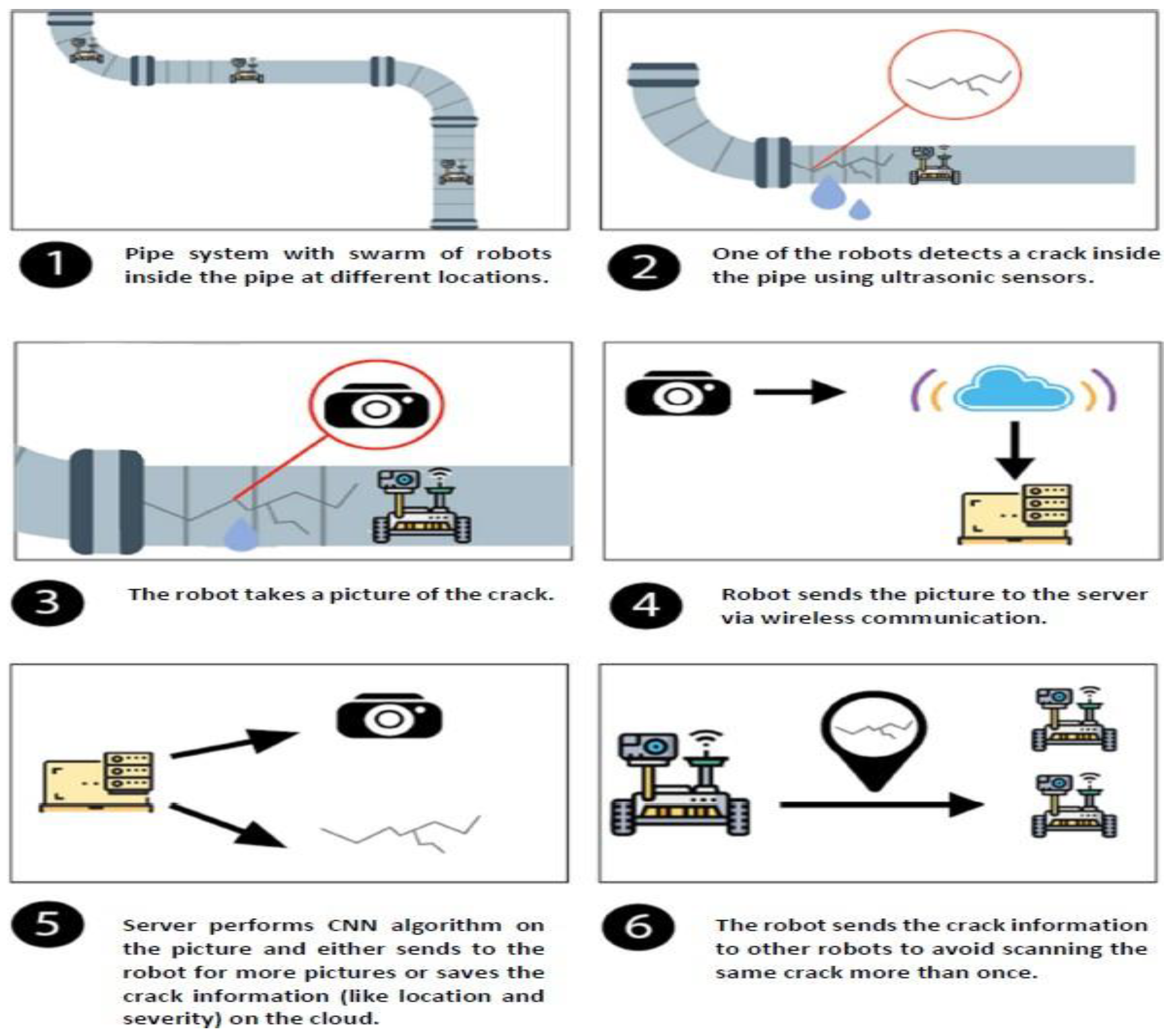
Figure 2.
A typical architecture of a CNN [14].
Figure 2.
A typical architecture of a CNN [14].
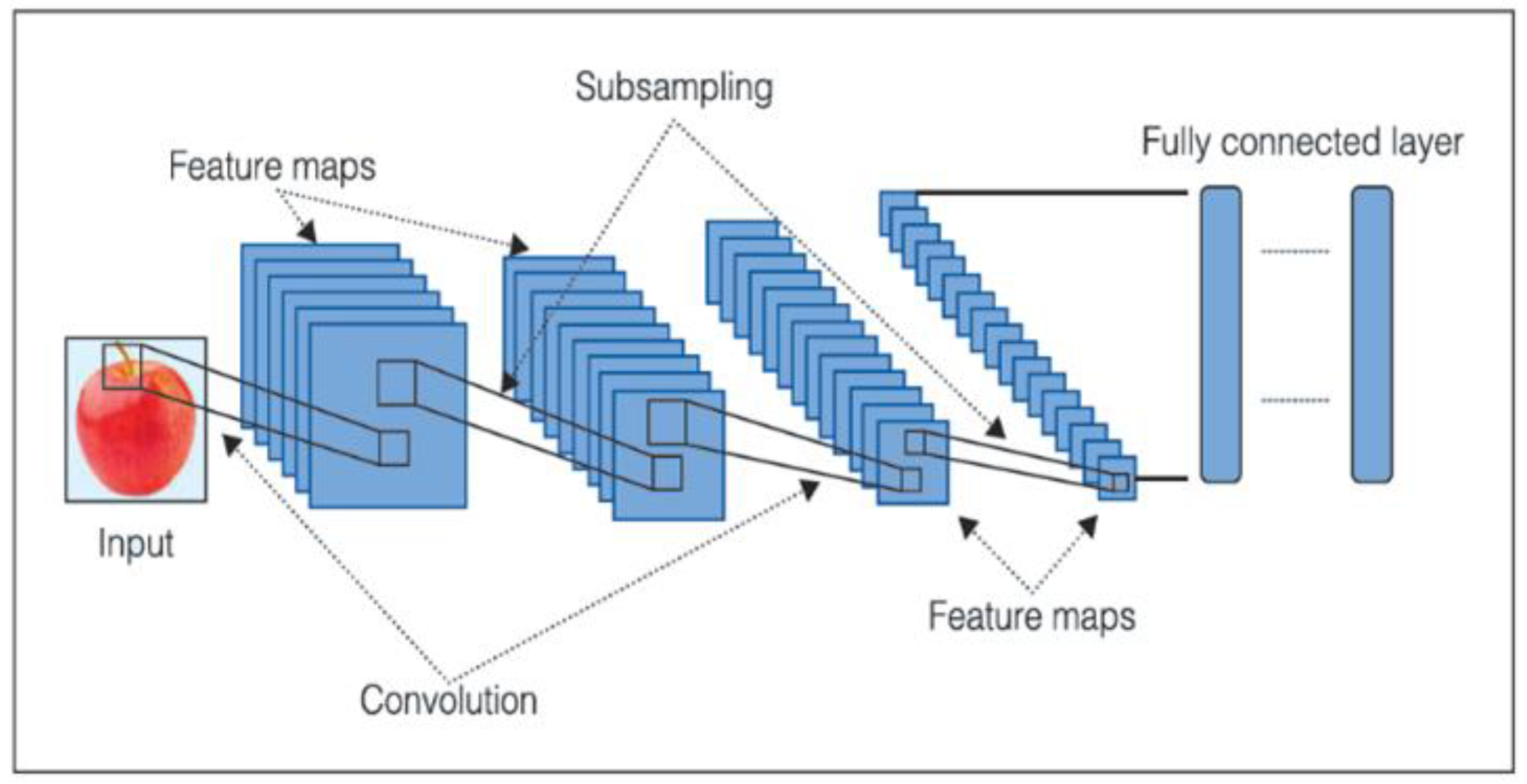
Figure 3.
Flowchart of tasks at the robots.
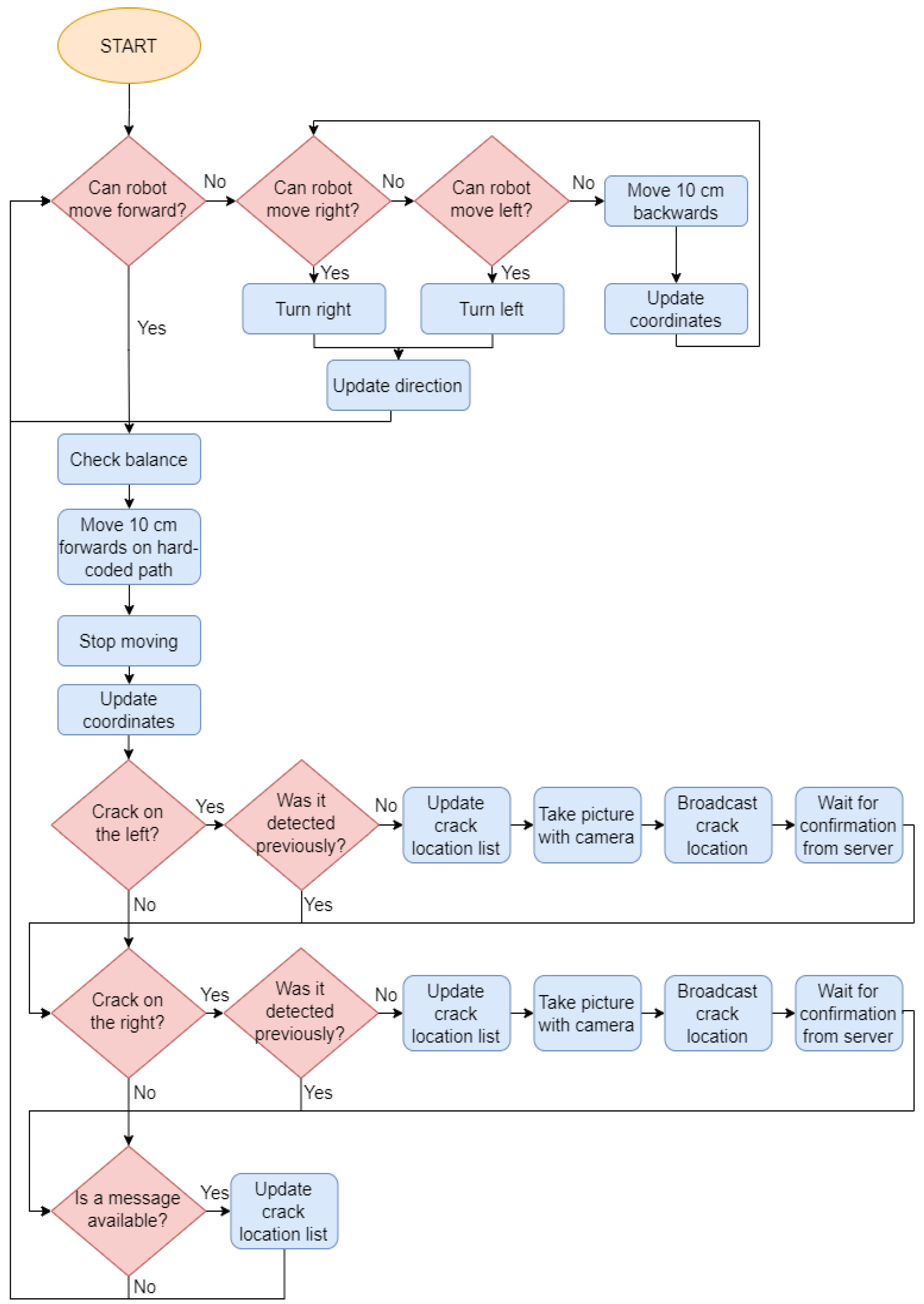
Figure 4.
Flowchart of tasks at the control center.
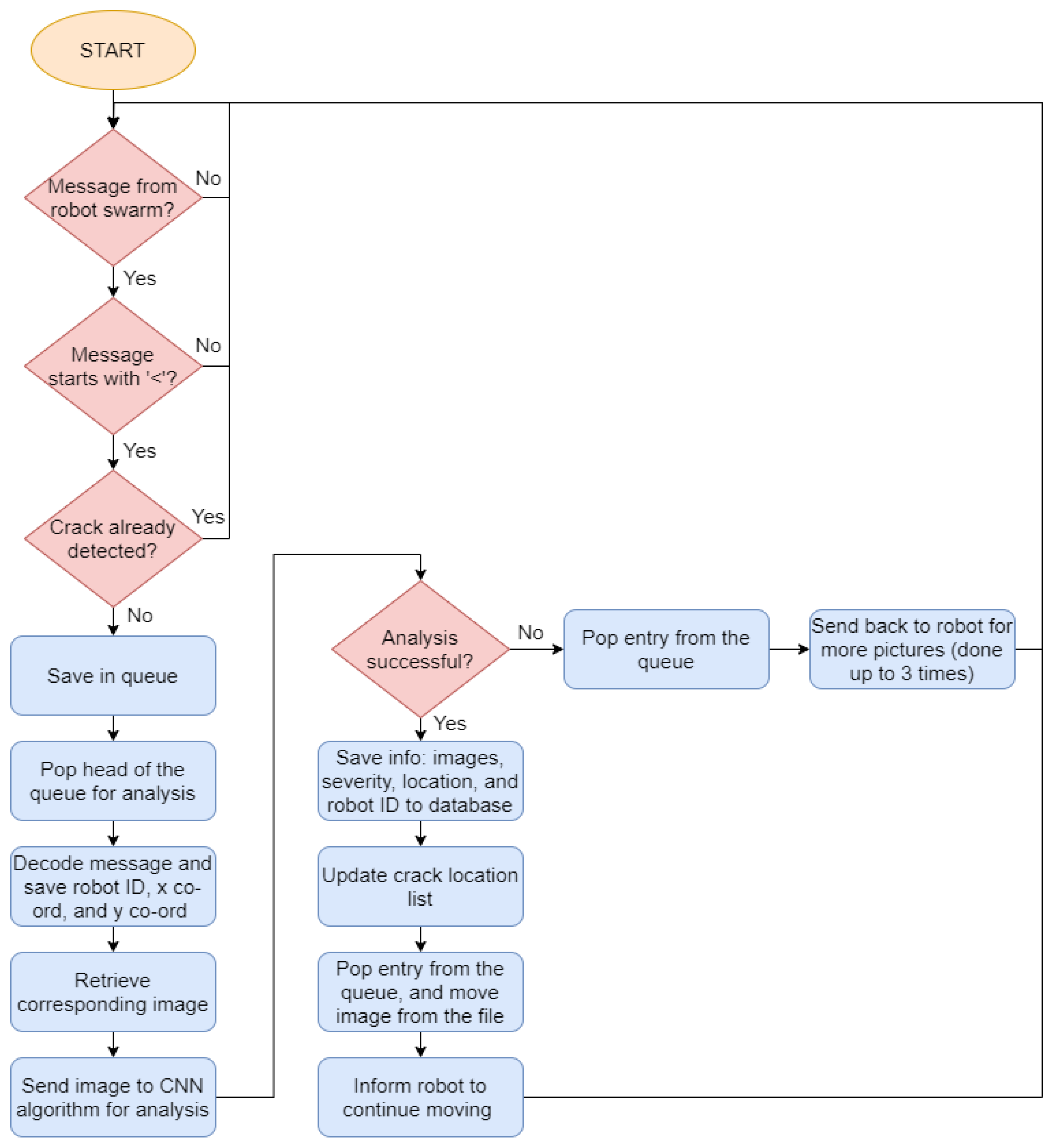
Figure 5.
Images from the training dataset: (a) Clear of cracks, (b) Shallow crack, and (c) Deep crack.
Figure 5.
Images from the training dataset: (a) Clear of cracks, (b) Shallow crack, and (c) Deep crack.
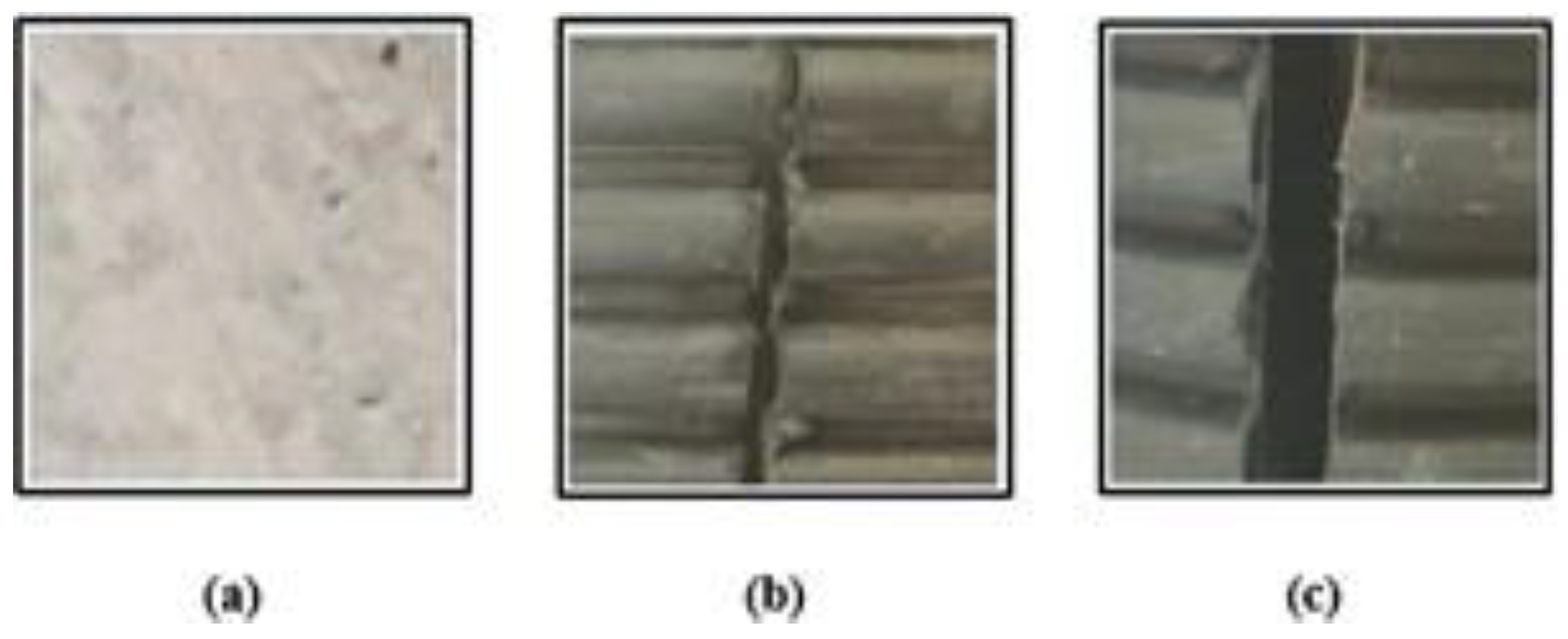
Figure 6.
Images taken from the custom-made pipes: (a) Clear of cracks, (b) Shallow crack, and (c) Deep crack.
Figure 6.
Images taken from the custom-made pipes: (a) Clear of cracks, (b) Shallow crack, and (c) Deep crack.
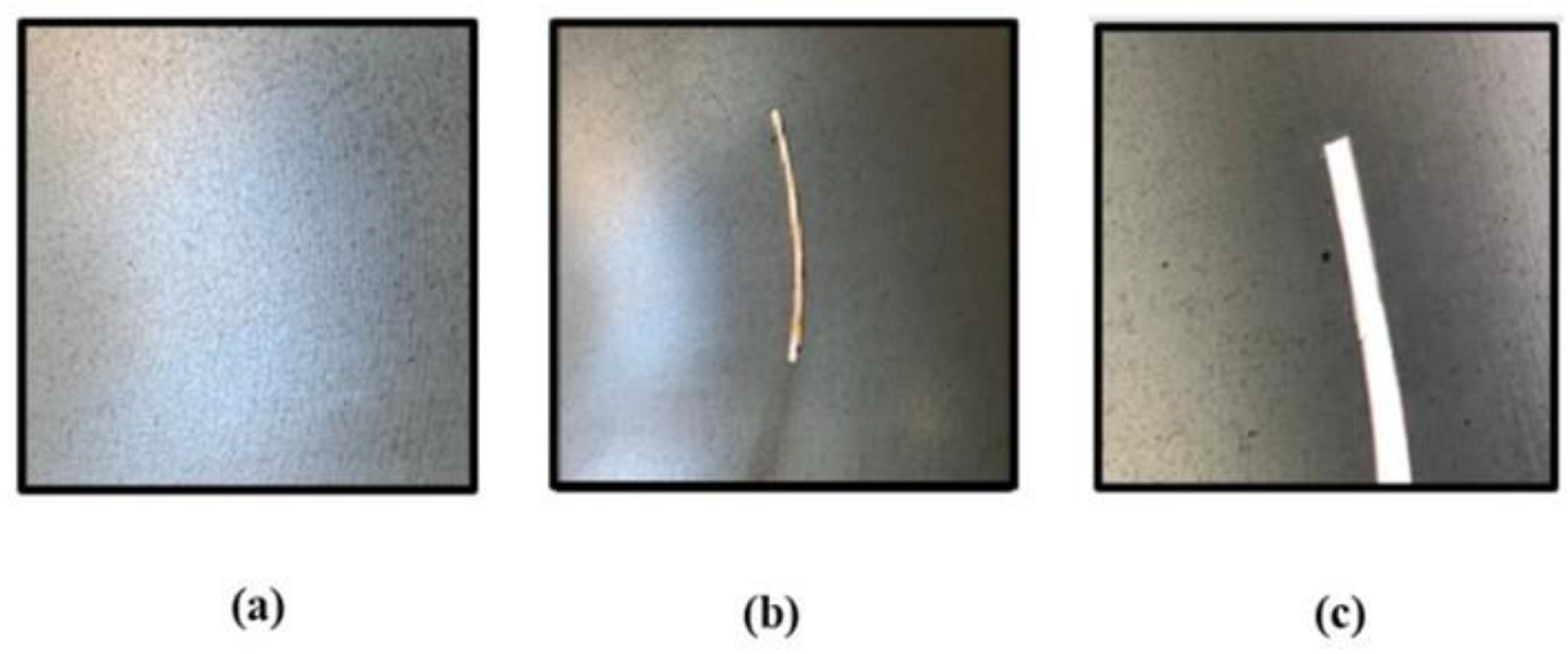
Figure 7.
The CNN model implemented at the control center of PLIERS.
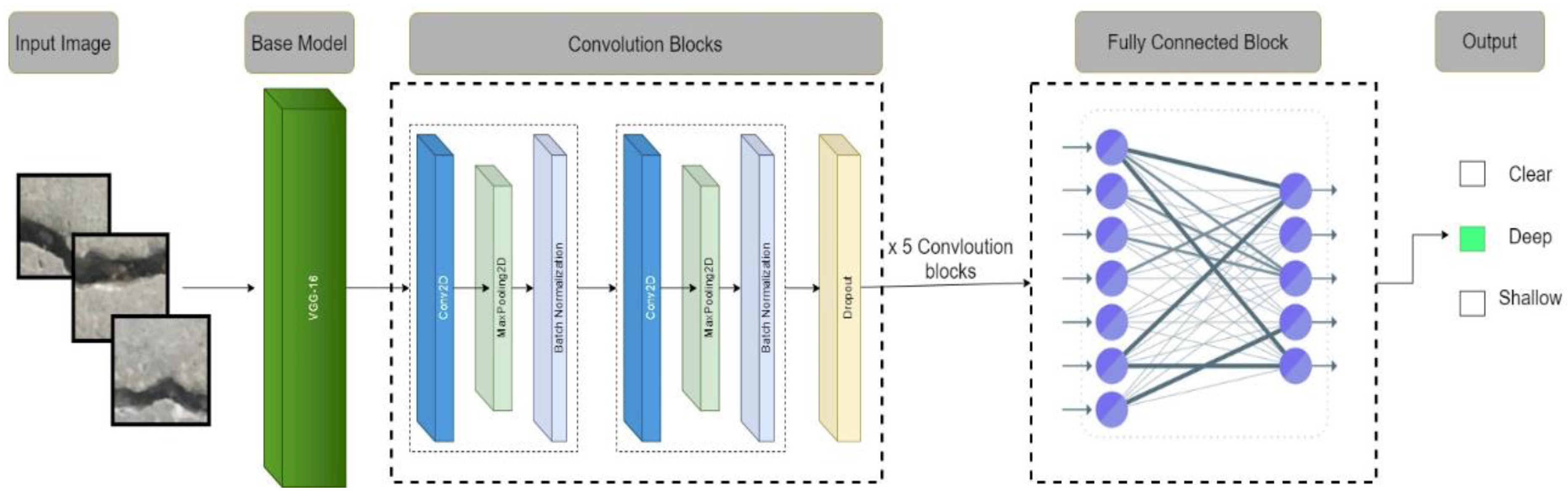
Figure 8.
The pipe system used in testing PLIERS.
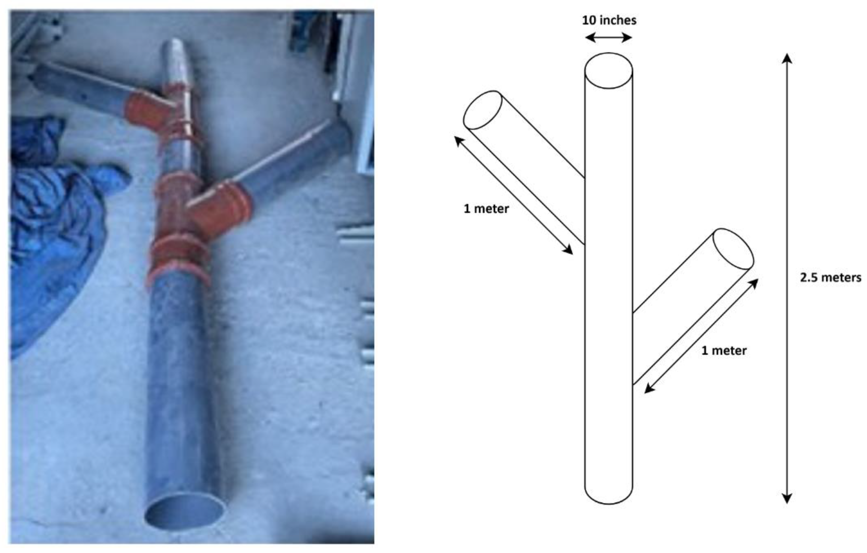
Figure 9.
PLIER’s CNN model accuracy and loss over 150 epochs.
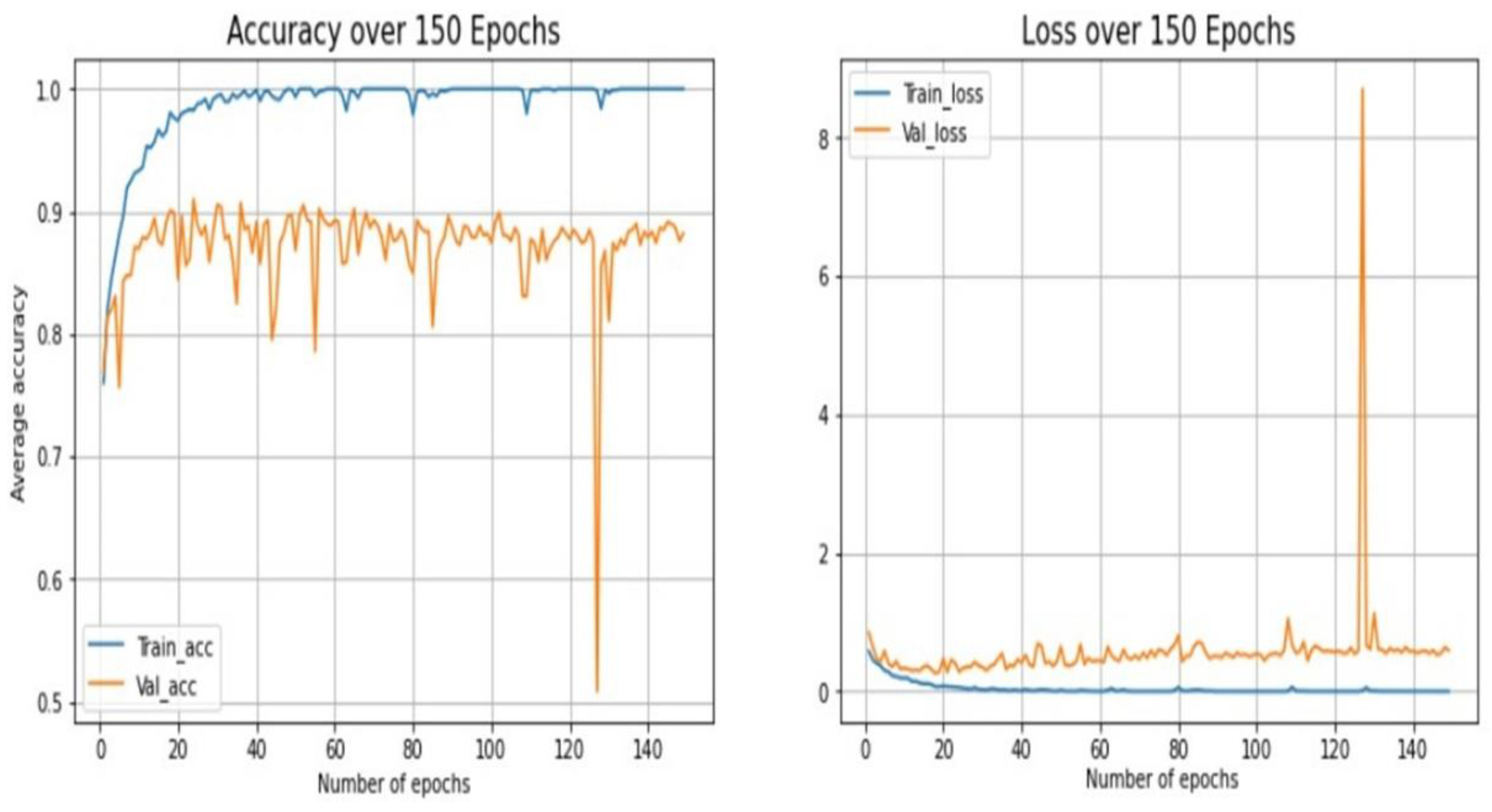
Figure 10.
Confusion matrix of PLIERS CNN.
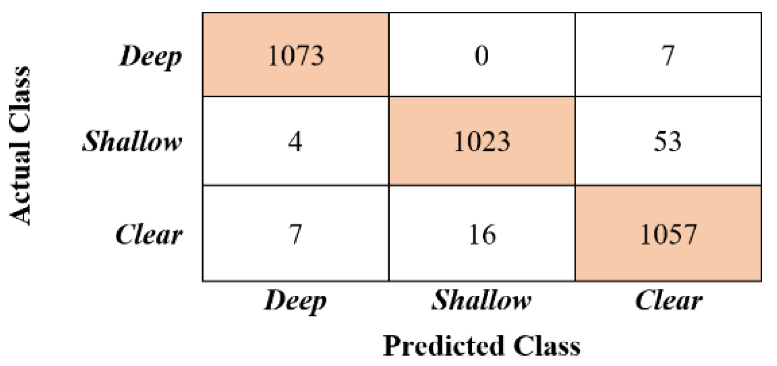
Figure 11.
PLIERS database.


Table 1.
Performance metrics scores for PLIERS CNN model.
| Classifications | Precision | Recall | F1 Score |
| Clear | 0.95 | 0.98 | 0.96 |
| Shallow | 0.98 | 0.95 | 0.97 |
| Deep | 0.99 | 0.99 | 0.99 |
Disclaimer/Publisher’s Note: The statements, opinions and data contained in all publications are solely those of the individual author(s) and contributor(s) and not of MDPI and/or the editor(s). MDPI and/or the editor(s) disclaim responsibility for any injury to people or property resulting from any ideas, methods, instructions or products referred to in the content. |
© 2024 by the authors. Licensee MDPI, Basel, Switzerland. This article is an open access article distributed under the terms and conditions of the Creative Commons Attribution (CC BY) license (http://creativecommons.org/licenses/by/4.0/).
Copyright: This open access article is published under a Creative Commons CC BY 4.0 license, which permit the free download, distribution, and reuse, provided that the author and preprint are cited in any reuse.


