
Submitted:
18 October 2024
Posted:
22 October 2024
You are already at the latest version
Abstract
The lightweight and displacement-stable design of the mechanical support structure within the APTS (Acquisition, Pointing, and Tracking System) is crucial for enhancing the payload capacity of remote sensing, satellite communication, and laser systems, while still meeting specified functional requirements. This paper adopts the Solid Isotropic Material with Penalization (SIMP) method to investigate the structural topology optimization of the L-shaped bracket in the APTS, aiming to minimize structural compliance while using volume, key point displacement, and maximum stress as constraints. In the optimization model, differences in the topology of the L-shaped bracket structure are explored to minimize structural compliance, which is done under volume, key point displacement, and stress constraints, the results are compared with the initial reinforced structure. The innovative L-shaped bracket structure obtained through topology optimization uses significantly less material than the initial reinforced design, while still meeting the displacement and stress constraints. After smoothing, rounding, and finite element analysis, the displacement and stress performance of the optimized L-shaped bracket structure satisfies the set constraints. The method proposed in this paper offers an innovative solution for the lightweight design of mechanical support structures in APTS, with significant engineering application potential.
Keywords:
structural topology optimization
; acquisition
; pointing
; and tracking system
; displacement and stress constraints
; minimization of structural compliance
; solid isotropic material with penalization
1. Introduction
Lightweight structural design is a key technology in industries such as aerospace and transportation machinery, directly influencing whether equipment structures meet predetermined functions and critical performance indicators, including economic and environmental factors. The structure acts as the skeleton of aerospace equipment and has long been the primary focus of system lightweight. Achieving lightweight material structures requires the efficient use of high-performance materials, structural optimization methods, and advanced manufacturing techniques. This is accomplished by optimizing the topological layout of materials and parameters within the structural space to enhance load-bearing capacity and reduce weight [1,2,3].
The integrated multi-target APTS system enables multi-access space laser communication and the capture of low Earth orbit debris while taking into account the carrier satellite's mass and space constraints. During satellite launch, the APTS system, as part of the satellite payload, experiences harsh mechanical conditions such as shock and vibration. Thus, the traditional collimation frame in the APT system uses a gimbal-based structure for enhanced mechanical strength. As shown in Figure 1, to achieve a larger pitch angle, a typical gimbal-based collimation frame consists of a U-shaped or L-shaped frame, optical lens, pitch axis, azimuth axis, and pedestal. While the U-shaped frame offers better mechanical properties, it is heavier, significantly increasing the cost of satellite launches. This paper employs a hybrid method of topology optimization (TO) and a gradient-based optimization algorithm to optimize the L-shaped bracket and achieve a lightweight design for the APT system.
Topological optimization of structures is an effective method for achieving innovative lightweight in aerospace equipment. Additive manufacturing offers greater potential for realizing models derived from structural topological optimization. The flexibility of additive manufacturing processes facilitates the implementation of topological optimization designs, offering broad prospects for aerospace applications. As shown in Figure 2, engineers from Altair, Airbus, and BAE Systems jointly used the OptiStruct software platform to perform topology, shape, and size optimization on the ribs of the Airbus A380 wing. This resulted in a 500kg weight reduction for each A380 aircraft, significantly improving performance and reducing operating costs for airlines.
Topology optimization is one of the most crucial approaches to lightweight structures. It provides designers with a conceptual design at the initial stage of engineering structural design, enabling the adoption of optimal layout solutions, which results in greater economic benefits compared to sectional optimization and shape optimization. It has become a hot topic in structural optimization design research today. It explores the interconnection of structural components, the topology forms such as the presence or absence of voids, and the number, and the position of voids, allowing structures to achieve optimal performance indicators under constraints such as balance, stress, displacement, and others [4,5]. The pioneering work in topology optimization of continuum structures can be traced back to Cheng and Olhoff's [6] 1981 research on the minimum compliance of solid plates. They were the first to introduce the concept of microstructures into structural optimization, describing the distribution of reinforcing ribs on plates using microstructural parameters (the number of ribs per unit length). This led to the optimal design of variable-thickness plates with ribbed reinforcements, allowing for infinitely fine and dense ribs. In 1988, Bendsoe and Kikuchi [7] introduced the concept of material distribution within the design domain to describe structural topology, proposing the Homogenization Method for topology optimization. This method assumes that the design domain consists of cells with centred voids, where the voids have predefined geometric shapes (such as squares) and can be described by one or more size variables. By treating the size variables of the voids as design variables, the topology optimization problem is transformed into one of redistributing material within the design domain through size optimization. This work pioneered a new direction in continuum structural topology optimization. Evolutionary Structural Optimization (ESO) [8], the Level Set Method [9], and Solid Isotropic Material with Penalization (SIMP) [10,11,12] are also mainstream topology optimization methods. With its long development history and simple model, SIMP is considered a classic topology optimization method [13]. It serves as the theoretical foundation for mainstream commercial topology optimization software, including OptiStruct, which was used in this study. The most commonly used material interpolation method in density-based approaches is based on the power-law form of orthotropic material density interpolation theory [14]. By introducing penalty factors to drive values towards zero or one, the intermediate density converges to these extremes, allowing for the addition or removal of intermediate-density elements, ultimately forming the topology structure. Additionally, other topology optimization methods include the Geometrical Projection Method (GPM) [15], the Moving Morphable Component (MMC) method [16], and the Moving Morphable Bar (MMB) method [17]. These methods describe topology optimization problems by defining components or bars, offering high computational efficiency and yielding optimal structures that are simple and intuitive [18].
The application of structural topology optimization in lightweight and multifunctional design of aerospace structures is extensive, significantly enhancing the performance and design flexibility of aircraft and spacecraft. Aerospace structures demand high strength and low weight to withstand the complex loading conditions of extreme environments, such as high temperatures, high speeds, vibrations, and impacts. Traditional design methods often struggle to achieve the best balance between performance and weight, whereas topology optimization allows designers to optimize material distribution within the structure, significantly reducing material usage while maintaining strength and stiffness, thereby achieving lightweight structures. In aerospace structures, topology optimization is widely used in key components such as wings, fuselage frames, support structures, and engine parts. For example, wings and internal supports of the fuselage designed using topology optimization can effectively reduce weight while maintaining or even enhancing their bending and torsional stiffness. Additionally, topology optimization can generate porous or lattice structures based on different functional requirements. This multifunctional design not only reduces weight but also improves the structure's thermal management or optimizes its aerodynamic performance. Moreover, topology optimization combined with additive manufacturing (3D printing) plays a crucial role in realizing complex geometries. Traditional manufacturing processes often struggle with complex shapes, while additive manufacturing can directly produce complex structures generated by topology optimization, further expanding design freedom. This enables more flexible and diverse designs for aerospace components, allowing for efficient integration of functions such as load-bearing, heat dissipation, and wave absorption within a single optimized part. París et al. [19] presented a minimum weight formulation with stress constraints that allow for to avoidance of most of the drawbacks associated with maximum stiffness approaches. López et al. [20] developed a methodology that combines the Sequential Optimization and Reliability Assessment (SORA) with external optimization software to perform Reliability-Based Topology Optimization (RBTO) of aeronautical structures. Based on the finite element method (FEM) and additive manufacturing (AM) technologies, Berrocal et al. [21] used the topological optimization methodology to redesign the connector support of the VEGA space launcher, a typical lever component from civil aircraft and housing part from fan cowl structures.
Sigmund [22] described the background of the method and showed some applications, ranging from the design of materials with ‘exotic’ properties over microscopic robots to the design of large–scale satellite structures. Zhu et al. [23] pointed that additive manufacturing is an advanced manufacturing technique for building as-designed structures via layer-by-layer joining material, providing an alternative pattern for complex components and reviewed the main content and applications of the research on the integration of topology optimization and additive manufacturing in recent years, including multi-scale or hierarchical structural optimization design and topology optimization considering additive manufacturing constraints. The mechanical performance of the 3D-printed beam meets the standards of forged parts, demonstrating the significant advantages of additive manufacturing in lightweight. [24]. State-of-the-art research for structural topology optimization and their applications in aerospace structures in industries can be found in Zhu et al. [23]; Sigmund and Maute [25]; Eschenauer, and Olhoff [26]; Wu et al. [27].
The structure of satellite launch devices is complex, with the camera support frame positioned at a critical junction between key components. It also experiences impacts and vibrations during satellite transport and launch. Operating in such harsh environments poses significant challenges to the mechanical performance of the camera support structure. It must provide sufficient strength and stiffness while minimizing weight to reduce the satellite's burden. This study performs lightweight topological optimization on the camera support structure.
The organization of this paper is as follows: Section 1 provides an overview of optimization theory and structural mathematical models. Section 2 presents the initial mechanical analysis of the structure. Section 3 discusses the results of the topological optimization design. Section 4 examines and discusses numerical examples, followed by a summary of the findings.
2. Material Interpolation Format and Mathematical Model for Structural Topology Optimization of the APTS Mechanical Support Structure Bracket
2.1. Material Interpolation Format of SIMP and Structural Analysis
Structural topology optimization aims to determine the optimal material distribution within a given design domain to achieve desired performance objectives while satisfying various constraints. The Solid Isotropic Material with Penalization (SIMP) method, pioneered by Bendsøe and Sigmund [28], revolutionized the field by formulating the optimization problem as a continuous material distribution problem, which enables efficient exploration of design spaces. The SIMP method is a widely used approach in structural topology optimization. It seeks to find the optimal material distribution within a given design domain to minimize structural compliance while satisfying various constraints. The basic idea of the SIMP material interpolation method is to use the artificial material density as a design variable. Through material interpolation models such as SIMP or RAMP [29], the relationship between artificial material density and the material elastic tensor is established. By varying the artificial density between 0 and 1, the optimization of two-phase material distribution is achieved. The SIMP method builds upon the concept of density-based optimization, where the material density of each finite element is used as a design variable. The method’s foundation lies in formulating an objective function to minimize structural compliance or maximize stiffness, subject to volume and other constraints. For the topology optimization model presented in this paper, the SIMP interpolation model is used. In SIMP, the relationship between material density and material properties is described using a material interpolation function. A commonly used interpolation function is:
where, represents the elastic modulus of the material, denotes the minimum allowable elastic modulus, ensuring numerical stability and avoiding singularities, usually is a small value (often chosen as a fraction of e.g., ) to avoid singular stiffness matrices in finite element analysis, is the maximum elastic modulus, denotes the material density design variable for the element, ranging from 0 (void) to 1, where represents solid material and represents void, and is the penalization factor influencing the distribution of material densities, typically , promoting a binary material distribution. For numerical stability, typically, let in the present paper. Under the effect of , intermediate density values gradually approach 0 or 1. A larger value of results in a stronger penalty effect on intermediate densities. However, should not be too large, as an excessively large can also lead to singularity in the matrix, making it impossible to find feasible solutions to the optimization problem. When or , it represents the design point as solid material or void material, corresponding to "black" or "white" design in topology optimization. The parameter represents the penalization exponent. By employing a continuous penalization strategy on the artificial density , design variables tend towards 0 or 1 as much as possible, facilitating clear material selection and achieving structural topology optimization design.
The element stiffness matrix is computed based on the material properties (such as Young's modulus) and the geometry of the element. For a linear elastic material, the element stiffness matrix is typically calculated using:
where is the strain-displacement matrix; is the volume of the element.
The global stiffness matrix is constructed by assembling the stiffness matrices of all the individual elements. The global stiffness matrix represents the stiffness properties of the entire structure.
where is the total number of elements in the discretized design domain. Structural analysis in the context of SIMP involves solving the equilibrium equations of the structure, where the stiffness matrix is a function of the interpolated material properties. The design domain is discretized into finite elements. Each element is assigned a density variable . The global stiffness matrix is assembled using the element stiffness matrices . The equilibrium equation for the structure is given by:
where is is the global displacement vector; is the global force vector. In static structural optimization, minimizing the compliance of a structure is a common objective. Compliance is a measure of the flexibility of the structure under applied loads, and minimizing it effectively means maximizing the stiffness of the structure for given loads and boundary conditions. Compliance is defined as the work done by the external forces on the structure's displacements, and it is mathematically expressed as:
2.2. Mathematical Model for Structural Topology Optimization of the APTS Mechanical Support Structure Bracket
Structural topology optimization aims to determine the optimal material distribution within a design domain to achieve specific performance objectives while adhering to defined constraints. The Solid Isotropic Material with Penalization (SIMP) method is one of the most widely adopted approaches for this purpose. The SIMP method formulates the problem as one of optimizing material layout, where the goal is to identify the best distribution of material and voids within a continuous region. This ensures that the structure meets performance criteria such as stress resistance and flexibility under loading conditions. The primary goal in the topological optimization of continuum structures is to identify a material subregion within the design domain Ω, with a specified volume, such that the objective function achieves an extremum. Objectives may include maximizing stiffness under applied loads, minimizing weight to achieve a lightweight design, controlling deformations by minimizing weight with displacement constraints, or maximizing natural frequencies to avoid resonance. Additionally, compliance minimization ensures structural safety under stress constraints, while reliability-based optimization accounts for uncertainties in material properties or loading conditions.
where represents the design variables, such as the dimensions of the structure;denotes the design objective, such as mechanical performance or weight; and are the design responses that need to be constrained, such as constraints on the deformation and stress levels of the structure.
In Eq. 6: V represents the volume of the optimized structure, C is the total compliance of the structure, is the displacement vector of the structure, is the stiffness matrix of the structure, is the pseudo−density of the element, is the stiffness matrix of the element, is the displacement vector of the element, is the load vector of the structure, is the initial volume of the design domain of the structure, is the volume of the structure to be preserved after optimization, and are the minimum and maximum pseudo-density constraints to prevent singularity of the overall stiffness matrix, is the volume ratio factor for optimization, S represents displacement,represents the maximum displacement value, represents the structural strength, represents the permissible stress of the material, n is the number of finite elements in the structure, p is the penalty factor. This model penalizes intermediate variables using the isotropic material penalty model SIMP, where the material's elastic modulus according to changes in the pseudo-density, as shown in Eq. 1.
3. Explicit Sensitivity Analysis of Objective Functions and Constraints
3.1. Sensitivity of Compliance to Design Variables
From the perspective of external forces acting on the structure, the work done by these forces is stored internally as strain energy. Numerically, the strain energy is proportional to the product of the external forces and the resulting deformation. Specifically, the strain energy can be expressed as the integral of the product of the applied force and the structural displacement.
In Eq. 7, each term is defined as follows: C(X) represents the total compliance of the structure, obtained by summing up the strain energies of all elements within the structure; is the external load vector, representing the load conditions applied to the structure; is the displacement vector of the structure under the action of external loads; is the displacement vector of the individual element, and is the stiffness matrix of the solid element.
Using the chain rule of differentiation, the derivative of the stiffness constraint function in the optimization problem with respect to the design variable can be expressed as:
3.2. Sensitivity of Displacement Constraints with Respect to Design Variables
As a result of density filtering applied to the design variables, and using the chain rule of differentiation, the sensitivity of the volume minimization objective function can be expressed as:
In Eq. 9, represents the volume of each element, which is assumed to be a fixed value. Due to the use of density filtering for the design variables, the derivative of the density variable with respect to the design variable can be expressed as:
The sensitivity information of displacement constraints with respect to element density is also obtained using the adjoint variable method. By introducing Lagrange multipliers, the Lagrangian function for the compliance constraint is constructed as:
In the equation, L is the displacement coefficient matrix constructed to obtain the displacement at the loading point.
The derivation of the sensitivity of the Lagrangian function with respect to the element density is as follows:
Neglecting the topological load correlation, i.e., , the equation simplifies to:
To eliminate the unknown displacement sensitivity term, setting the term containing to zero, we obtain the adjoint variable
The corresponding sensitivity equation can be transformed into:
3.3. Sensitivity of Stress Constraints with Respect to Design Variables
The sensitivity information of stress with respect to element density is obtained through the adjoint variable method. By introducing Lagrange multipliers, the Lagrangian function θ for stress is constructed as:
The derivation of the sensitivity of the Lagrangian function with respect to the element density is as follows:
It is worth noting that the correction factor updates the sensitivity of global stress to element density. According to the chain rule, the derived information can be obtained as follows:
From the above equation, it can be seen that the sensitivity of global stress can be obtained by computing the derivative of the p-norm function with respect to von Mises stress, the derivative of von Mises stress with respect to stress components, and the derivative of stress components with respect to design variables.
4. Structural Analysis of the APTS’ L-Shaped Bracket Structure
To provide displacement and stress constraint values for the topology-optimized design and compare its performance with the original reinforced bracket structure of the APTS, this section outlines the loading and boundary conditions of the original L-shaped bracket structure. It then conducts displacement and stress analysis on the structure. The bracket structure for an APTS must withstand various loading and boundary conditions to ensure stability and functionality. The loading conditions include static loads, such as the self-weight of the bracket and mounted equipment; dynamic loads from operational movements and vibrations; and environmental loads, such as temperature changes. Boundary conditions involve fixed supports that prevent translations and rotations, pinned supports that allow rotations, and sliding supports that accommodate thermal expansions.
4.1. Loading and Boundary Conditions of the APTS’ Bracket Structure
This study considers the static loads and boundary conditions of the bracket structure for the acquisition, pointing, and tracking system (APTS) to conduct innovative topology optimization under three models. The boundary conditions include fixed constraints on the supports, preventing displacement and rotation to ensure stability and precision. The three optimization models focus on minimizing structural compliance, accounting for displacement constraints, and addressing both displacement and stress constraints. These designs enhance the load-bearing capacity and vibration resistance of the bracket while reducing material usage, achieving a lightweight design that meets the requirements of high-precision tracking systems.
Figure 3 presents an oblique view of the initial reinforced bracket design for the APTS. The outer side plate of the support structure incorporates straight reinforcements, while the inner side is a flat plate. The loads and boundary conditions: the bottom surface of the lower bearing circular ring of the APTS support structure is fixed, while a concentrated load of 100N is applied perpendicular to the surface of the upper bearing circular ring.
4.2. Material Properties and Mesh Division of the APTS’ Bracket Structure
In this study, the optimized topology camera support structure is designed using isotropic material, specifically 2014 aluminium alloy. The corresponding mechanical properties are set as follows: elastic modulus E=73GPa, density =2800kg/m3, Poisson's ratio =0.33. The following Figure 4 illustrates the finite element mesh of the APTS support structure. This mesh is used to discretize the structure for numerical analysis, ensuring accurate simulation of the stress and deformation behaviour under applied loads and boundary conditions. The mesh division employs 1mm CTETRA tetrahedral elements, with a total of approximately 1 million mesh divisions.
4.3. Static Analysis of the APTS’ Bracket Structure
The stress and strain results obtained from the static analysis are shown in Figure 5. The analysis results show that the maximum displacement occurs at the topmost part of the structure, which is used as the displacement constraint. The maximum stress is observed in the central hole area and is taken as the stress constraint for optimization purposes.
The stress and strain results obtained from the static analysis are shown in Figure 5. According to the analysis, the maximum displacement is 6.04, occurring at the top of the structure. This maximum displacement value will be used as a displacement constraint in the subsequent topology optimization model. The maximum stress is 1.188Mp, occurring in the central hole area. This maximum stress value will be used as a stress constraint in the subsequent topology optimization model.
5. Topology Design Optimization of the APTS’ Bracket Structure
5.1. Preprocessing for the Geometric Model of the Support Structure
The optimization established model simplifies the original design structure by removing holes at the bottom of the non-design domain and certain geometric features of the design domain. It also fills in part of the design domain. The front and oblique view of the models are shown in Figure 6. The yellow part represents the design domain, while the remaining blue part represents the non-design domain.
5.2. Boundary Conditions and Loading Application for the Support Structure
Established using the same loading and boundary conditions as described in Section 3.1 of the initial model, as shown in Figure 7.
5.3. Manufacturing Constraints for the Topology Optimization of the Support Structure
The manufacturing constraints involved in this study include maximum size constraints, minimum size constraints, symmetry constraints, and mold release constraints. In particular, the minimum feature size refers to the allowed minimum scale of the region where the unit density is 1 in the optimization results. Applying a minimum feature size constraint can eliminate small force transmission paths in the optimization results and ensure that the minimum scale of the structure is greater than the minimum feature size. This ensures a relatively uniform material distribution, facilitates material flow in the casting process, and provides sufficient stiffness for tool machining. Generally, the minimum feature size should be greater than three times the average unit size.
The maximum feature size constraint means that the dimensional scale of the regions where the unit density is 1 in the optimization results cannot exceed this size. Therefore, the maximum feature size constraint helps eliminate material accumulation in the optimization results, avoids product defects caused by the manufacturing process (such as uneven heat dissipation during casting), and provides multiple force transmission paths to improve product reliability. The maximum feature size should be greater than twice the minimum feature size. In the camera bracket optimization process described in this paper, the minimum feature size is set to 4 mm, and the maximum feature size is set to 12 mm, based on the mesh size.
For castings or machined parts, it is necessary to consider mold release during manufacturing and the entry and exit of cutting tools. Therefore, there should be no material obstruction in either the mold release direction or the tool's entry and exit direction. In addition to specific manufacturing process constraints, mold release constraints also apply to the creation of reinforcement structures on the solid surface. In the camera bracket structure studied here, the mold release constraint is uniformly set as unidirectional, with the x-axis as the mold release direction.The symmetry constraint in OptiStruct is referred to as the 'Pattern Constraint'. Applying symmetry constraints to the design space generates symmetric designs, even for models with asymmetric meshes and boundary conditions, where the software forces results that are nearly symmetrical. In the support structure of the collection, pointing, and tracking system considered in this project, the symmetry plane is uniformly designated as the central axis symmetric plane of the support structure when applying symmetry constraints.
6. Numerical Examples and Discussion of Results
6.1. Topology Optimization Results Considering Displacement and Stress Constraints
Under the aforementioned loads and boundary conditions, with volume response minimization as the optimization objective, and with a displacement constraint of 0.0604mm at the highest point of the camera bracket structure, and a global stress constraint of 11.88MPa applied to the design domain, the optimization result is shown in Figure 8. It can be observed that in addition to excavating voids, there are arc transitions in areas with relatively high stress. The optimization iteration history is shown in Figure 9.
6.2. Topology Optimization Results for Minimizing Compliance Considering Volume Fraction Constraints
Minimizing compliance response is used as the optimization objective for the camera bracket structure under the aforementioned loads and boundary conditions. Considering the requirement for weight reduction, the volume fraction of the optimized design domain is constrained to 44% of the total structure volume. The optimized topology of the structure, obtained through the optimization algorithm, is shown in Figure 10, with its optimization iteration curve depicted in Figure 11.
6.3. Topology Optimization Structure Smoothing for the Support Structure
In Hyperworks, geometries of two different topology optimized models were extracted using the OSS-mooth tool in the Post panel. Since the output camera bracket model contains elements with multiple density components, the design not only needs to meet functional and performance requirements but also requires good manufacturing processes. Taking all factors into consideration, the model was re-geometrically modeled. The result of re-modeling the topology optimization results considering displacement constraints is shown in Figure 13 (a). The final model weight is 0.648kg, compared to the original model weight of 0.680kg of the same material, resulting in a weight reduction of 4.7%. The result of re-modeling the topology optimization results considering both displacement and stress constraints is shown in Figure 13 (b). The final model weight with the same material is 0.635kg, resulting in a weight reduction of 6.6%. The result of re-modeling the topology optimization results for compliance minimization considering volume fraction constraints is shown in Figure 13 (c). The final model weight with the same material is 0.655kg, resulting in a weight reduction of 3.6%.
In HyperWorks, the geometries of the optimized topology configurations are extracted using the OSS-mooth tool in the Post panel. Since the output camera bracket model contains elements with multiple-density components, the design must meet both functional and performance requirements while ensuring good manufacturability. Taking all factors into account, the model was re-modelled geometrically. The re-modelled topology optimized structure, considering displacement constraints, is shown in Figure 12(a). The final model weight is 0.648 kg, compared to the original weight of 0.680 kg for the same material, resulting in a weight reduction of 4.7%. The re-modelled structure, considering both displacement and stress constraints, is shown in Figure 12(b). The final weight is 0.635 kg, resulting in a weight reduction of 6.6%. The re-modelled structure for compliance minimization, considering volume fraction constraints, is shown in Figure 12(c). The final weight is 0.655 kg, leading to a weight reduction of 3.6%.
Figure 12.
The smoothed topology-optimized structure configurations for three different optimization models.
Figure 12.
The smoothed topology-optimized structure configurations for three different optimization models.
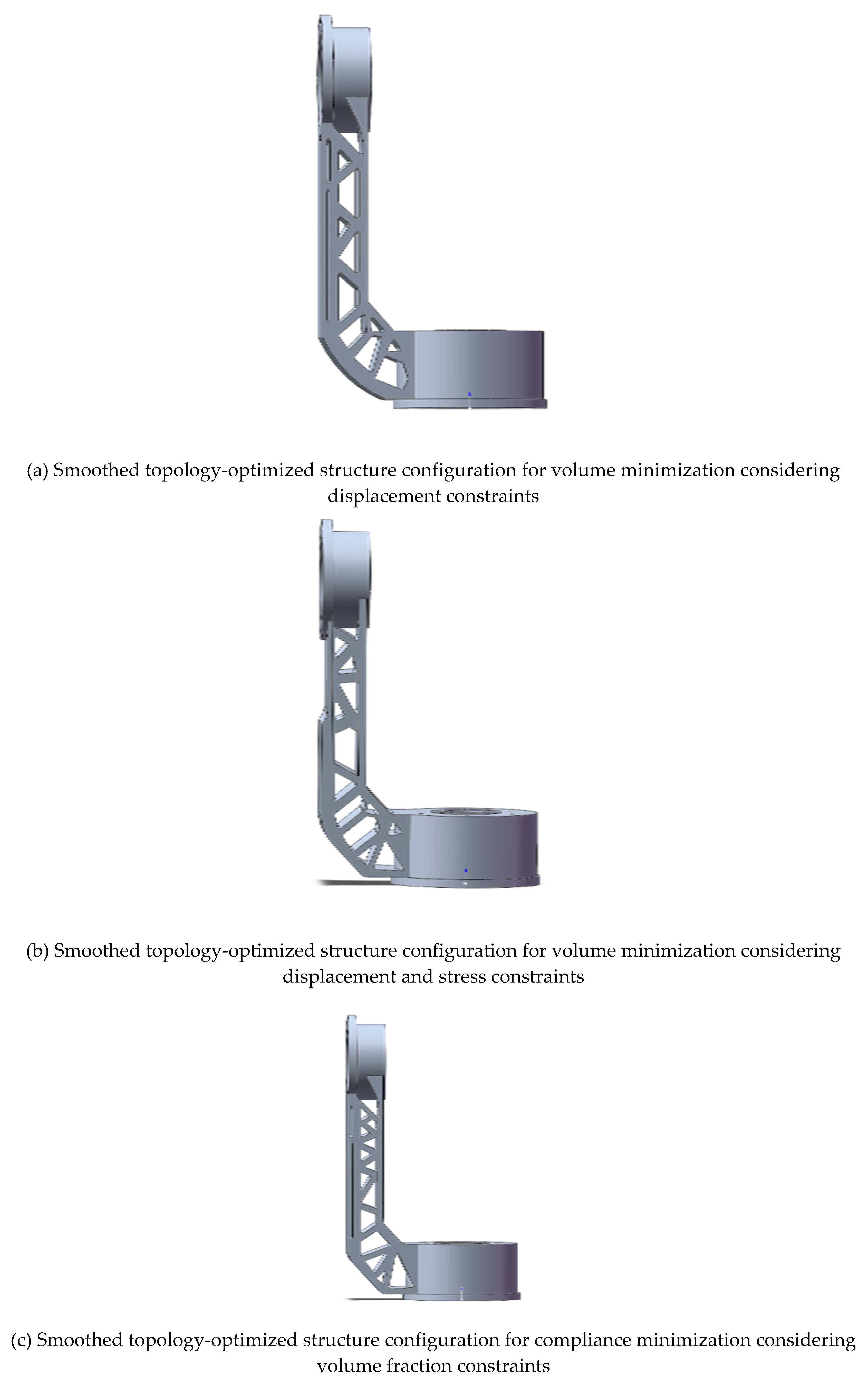
Figure 13.
Verification cloud map for the optimized structure considering displacement constraints.
6.4. Verification of the strength and stiffness of the optimized structure
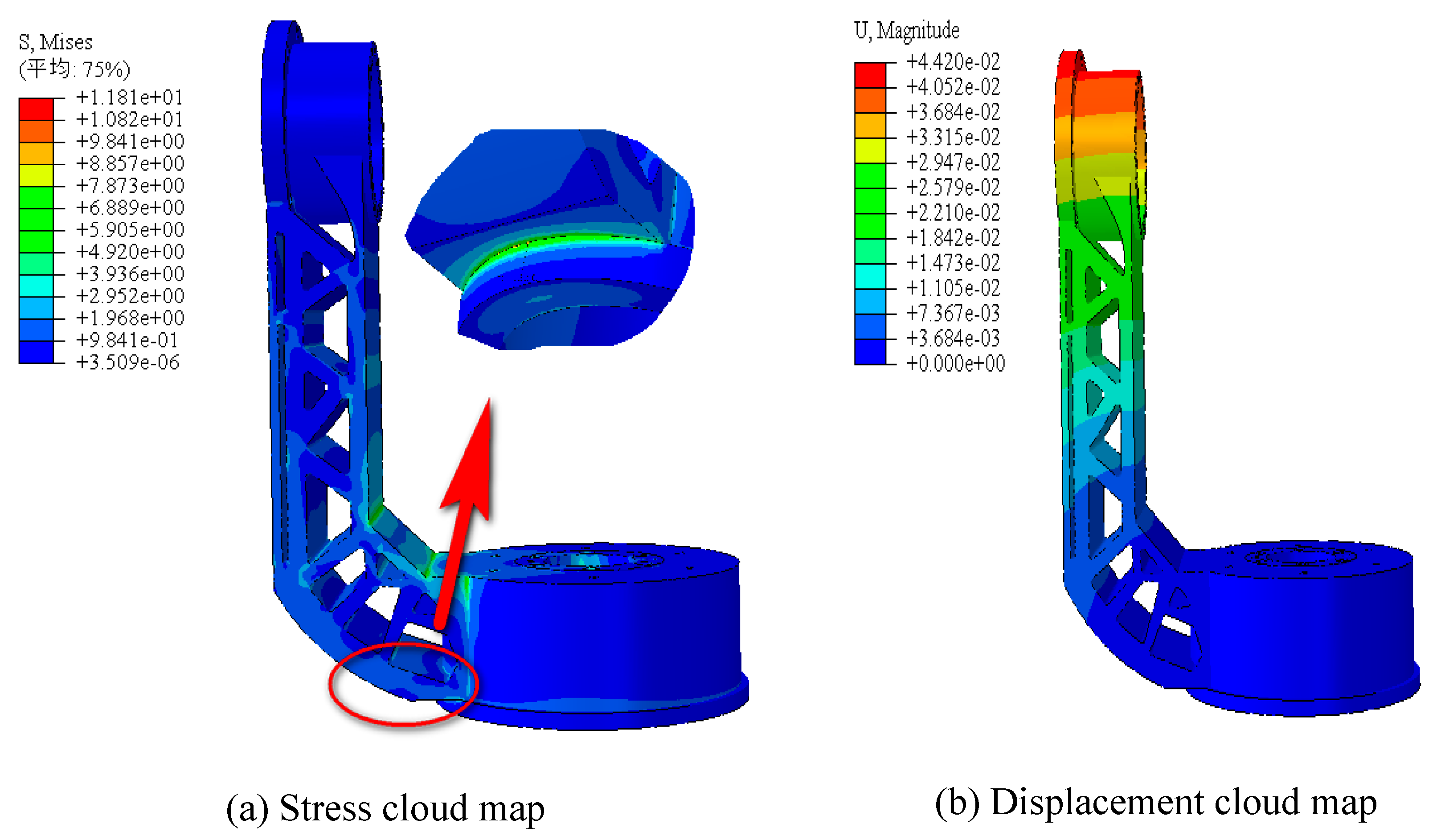
The stress and displacement cloud maps for the optimized results considering displacement constraints are shown in Figure 13. The maximum displacement is 0.04420mm.
The stress and displacement cloud maps for the optimized results considering displacement and stress constraints are shown in Figure 14. The maximum displacement is 0.04718mm.
The stress and displacement cloud maps for the optimized results for compliance minimization considering volume fraction constraints are shown in Figure 15. The maximum displacement is 0.04830mm.
From the preceding verification results, it can be observed that the two structures aimed at minimizing volume meet the requirements. However, for the structure aimed at minimizing compliance, the maximum stress in the verification results is 12.98 MPa, exceeding the stress constraint imposed by the optimization, though the values are relatively close. The summarized analysis results, under unchanged conditions such as load and material, are presented in Table 1.
7. Conclusion
The optimization of the L-shaped bracket structure in the APTS (Acquisition, Pointing, and Tracking System) has demonstrated the effectiveness of topology optimization in achieving a lightweight and displacement-stable design. By applying the Solid Isotropic Material with Penalization (SIMP) method, the study successfully minimized structural compliance while adhering to volume, displacement, and stress constraints. The results indicate that topology optimization is a viable solution for improving mechanical support structures in high-performance applications, such as satellite communication and remote sensing systems. The key conclusions from the optimization process are as follows:
- Volume Minimization with Displacement Constraints:
The optimized structure aimed at minimizing volume under displacement constraints achieved a weight reduction to 0.648 kg, with a maximum displacement of 0.04420 mm and a maximum von Mises stress of 11.81 MPa. This design met all functional requirements while significantly reducing material usage.
- 2.
- Volume Minimization with Displacement and Stress Constraints:
By introducing both displacement and stress constraints, the optimized structure further reduced weight to 0.635 kg, with a maximum displacement of 0.04718 mm and a maximum stress of 9.027 MPa. This solution achieved the best balance between structural stability and material efficiency, offering the lowest weight and lowest stress.
Compliance Minimization with Volume Fraction Constraints:
The compliance minimization approach, constrained by volume fraction, resulted in a structure with a weight of 0.655 kg and a maximum displacement of 0.04830 mm. Although the stress exceeded the optimization constraint at 12.98 MPa, the result is still relatively close, indicating that this approach could be further refined for stress control.
Overall, the proposed methodology offers a robust and practical solution for optimizing mechanical support structures in APTS, enhancing performance while reducing material usage, making it highly suitable for engineering applications.
Author Contributions
Bo Gao: Investigation, Resources, Writing – original draft. Hongtao Yang: Conceptualization, Methodology, Investigation, Resources, Writing – original draft. Weining Chen: Model background, Data curation, Validation. Hao Wang: Validation, Project administration, Supervision, Fund acquisition, Writing – review & editing. All authors have read and agreed to the published version of the manuscript.
Data Availability Statement
Some or all data, models, or codes that support the findings of this study are available from the corresponding author upon reasonable request.
Acknowledgments
Financial supports for this research were provided by the National Natural Science Foundation of China (No. 12272106). The supports are gratefully acknowledged.
Conflicts of Interest
The authors declare that they have no known competing financial interests or personal relationships that could have appeared to influence the work reported in this paper.
References
- Bendsøe MP. Topology design of structures, materials and mechanisms—status and perspectives.IFIP Conference on System Modeling and Optimization. Boston, MA: Springer US, 1999; 1-17.
- Zhu, J.; Zhang, W.; Beckers, P.; Chen, Y.; Guo, Z. Simultaneous design of components layout and supporting structures using coupled shape and topology optimization technique. Struct. Multidiscip. Optim. 2008, 36, 29–41, . [CrossRef]
- Duan, Z.; Liu, Y.; Fan, J.; Long, K.; Xu, B.; Zhu, J.; Yan, J. Concurrent multi-material and multi-scale design optimization of fiber-reinforced composite material and structures for minimum structural compliance. Compos. Struct. 2023, 311, . [CrossRef]
- Ho TH, Milner SD, Davis CC. Pointing, acquisition, and tracking system with omnivision.Free-Space Laser Communications V. SPIE, 2005; 5892: 420-431.
- Kaushal H, Jain VK, Kar S, Kaushal H, Jain VK, Kar S. Acquisition, tracking, and pointing. Free Space Optical Communication, 2017; 119-137.
- Cheng KT, Olhoff N. An investigation concerning optimal design of solid elastic plates. International Journal of Solids and Structures 1981; 17(3): 305-323.
- Bendsøe, M.P.; Kikuchi, N. Generating optimal topologies in structural design using a homogenization method. Comput. Methods Appl. Mech. Eng. 1988, 71, 197–224, . [CrossRef]
- Xie YM, Steven GP. Optimal design of multiple load case structures using an evolutionaryprocedure. Engineering computations, 1994; 11(4): 295-302.
- Allaire, G.; Jouve, F.; Toader, A.-M. Structural optimization using sensitivity analysis and a level-set method. J. Comput. Phys. 2004, 194, 363–393, . [CrossRef]
- Díaaz, A.R.; Kikuchi, N. Solutions to shape and topology eigenvalue optimization problems using a homogenization method. Int. J. Numer. Methods Eng. 1992, 35, 1487–1502, . [CrossRef]
- Suzuki, K.; Kikuchi, N. A homogenization method for shape and topology optimization. Comput. Methods Appl. Mech. Eng. 1991, 93, 291–318, . [CrossRef]
- Zhang, W.; Li, D.; Zhang, J.; Guo, X. Minimum length scale control in structural topology optimization based on the Moving Morphable Components (MMC) approach. Comput. Methods Appl. Mech. Eng. 2016, 311, 327–355, . [CrossRef]
- Rozvany G. The SIMP method in topology optimization-theoretical background, advantages and new applications.8th Symposium on Multidisciplinary Analysis and Optimization. 2000; 4738.
- Zuo, W.; Saitou, K. Multi-material topology optimization using ordered SIMP interpolation. Struct. Multidiscip. Optim. 2016, 55, 477–491, . [CrossRef]
- Norato J, Haber R, Tortorelli D, Bendsøe MP. A geometry projection method for shape optimization. International Journal for Numerical Methods in Engineering, 2004; 60(14): 2289-2312.
- Guo, X.; Zhang, W.; Zhang, J.; Yuan, J. Explicit structural topology optimization based on moving morphable components (MMC) with curved skeletons. Comput. Methods Appl. Mech. Eng. 2016, 310, 711–748, . [CrossRef]
- Hoang, V.-N.; Jang, G.-W. Topology optimization using moving morphable bars for versatile thickness control. Comput. Methods Appl. Mech. Eng. 2017, 317, 153–173, . [CrossRef]
- Coniglio, S.; Morlier, J.; Gogu, C.; Amargier, R. Generalized Geometry Projection: A Unified Approach for Geometric Feature Based Topology Optimization. Arch. Comput. Methods Eng. 2019, 27, 1573–1610, . [CrossRef]
- París, J.; Martínez, S.; Navarrina, F.; Colominas, I.; Casteleiro, M. Topology optimization of aeronautical structures with stress constraints: general methodology and applications. Proc. Inst. Mech. Eng. Part G: J. Aerosp. Eng. 2011, 226, 589–600, . [CrossRef]
- López, C.; Baldomir, A.; Hernández, S. Deterministic versus reliability-based topology optimization of aeronautical structures. Struct. Multidiscip. Optim. 2015, 53, 907–921, . [CrossRef]
- Berrocal, L.; Fernández, R.; González, S.; Periñán, A.; Tudela, S.; Vilanova, J.; Rubio, L.; Márquez, J.M.M.; Guerrero, J.; Lasagni, F. Topology optimization and additive manufacturing for aerospace components. Prog. Addit. Manuf. 2018, 4, 83–95, . [CrossRef]
- Sigmund, O. Topology optimization: a tool for the tailoring of structures and materials. Philos. Trans. R. Soc. A: Math. Phys. Eng. Sci. 2000, 358, 211–227, . [CrossRef]
- Zhu, J.; Zhou, H.; Wang, C.; Zhou, L.; Yuan, S.; Zhang, W. A review of topology optimization for additive manufacturing: Status and challenges. Chin. J. Aeronaut. 2020, 34, 91–110, . [CrossRef]
- Meng L, Zhang W, Quan D, Shi G, Tang L, Hou Y, Gao T. From topology optimization design to additive manufacturing: Today’s success and tomorrow’s roadmap[J]. Archives of Computational Methods in Engineering, 2020; 27: 805-830.
- Sigmund O, Maute K. Topology optimization approaches: A comparative review. Structural and multidisciplinary optimization, 2013; 48(6): 1031-1055.
- A Eschenauer, H.; Olhoff, N. Topology optimization of continuum structures: A review*. Appl. Mech. Rev. 2001, 54, 331–390, . [CrossRef]
- Wu, J.; Sigmund, O.; Groen, J.P. Topology optimization of multi-scale structures: a review. Struct. Multidiscip. Optim. 2021, 63, 1455–1480, . [CrossRef]
- Bendsøe, M.P.; Sigmund, O. Material interpolation schemes in topology optimization. Arch. Appl. Mech. 1999, 69, 635–654, . [CrossRef]
- Stolpe, M.; Svanberg, K. An alternative interpolation scheme for minimum compliance topology optimization. Struct. Multidiscip. Optim. 2001, 22, 116–124, . [CrossRef]
Figure 1.
APTS system. (a) U-shaped frame. (b) L-shaped frame.
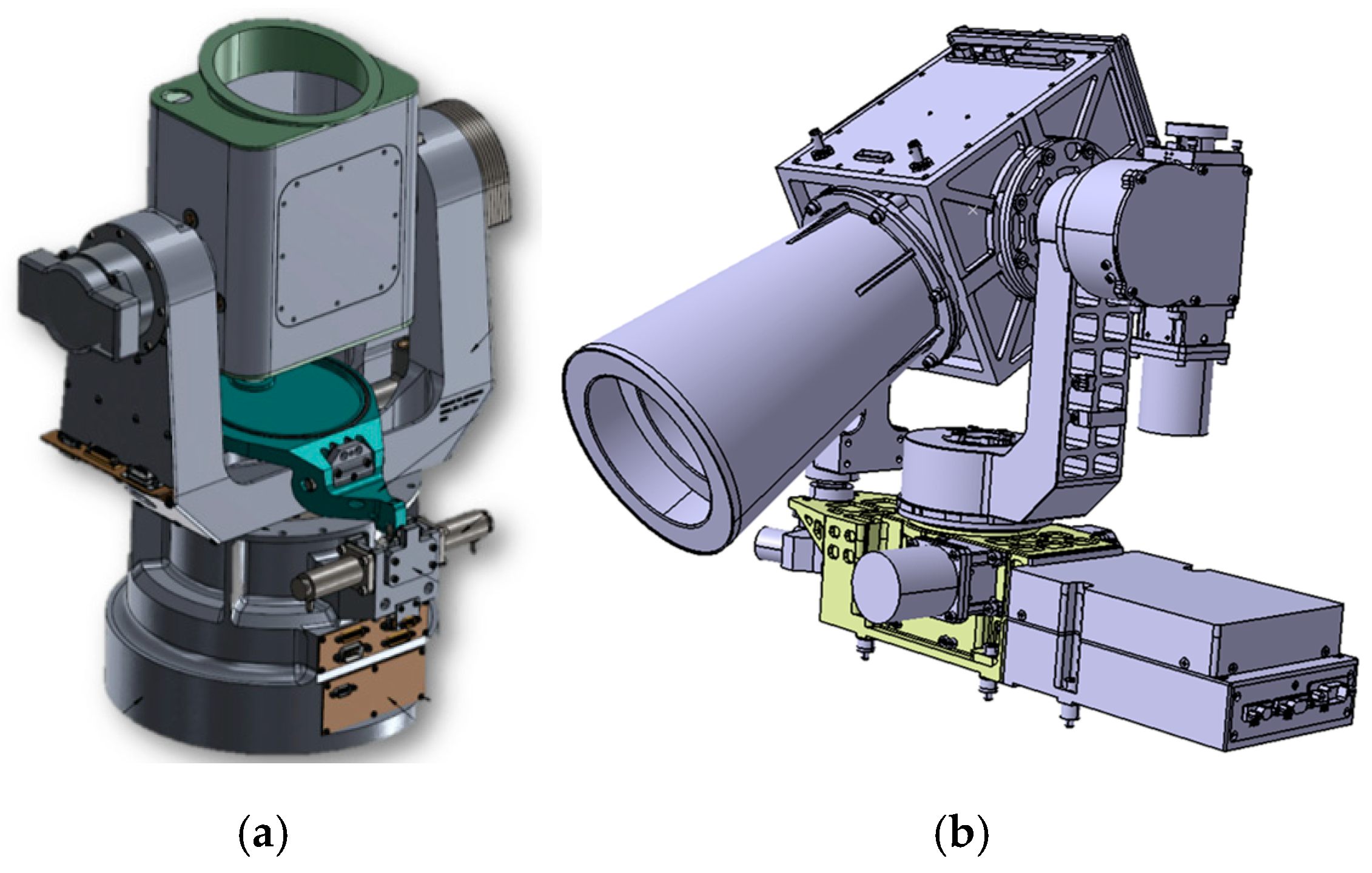
Figure 2.
Optimization design of the topology, shape, and dimensions of the A380 wing ribs.
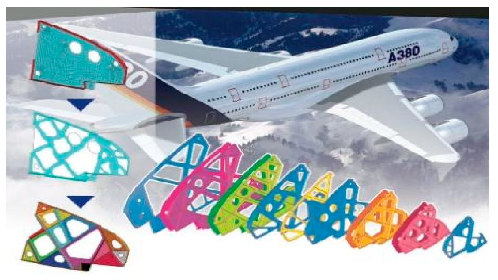
Figure 3.
Schematic of the initial design model loading and boundary conditions of the bracket structure for the acquisition, pointing, and tracking system.
Figure 3.
Schematic of the initial design model loading and boundary conditions of the bracket structure for the acquisition, pointing, and tracking system.
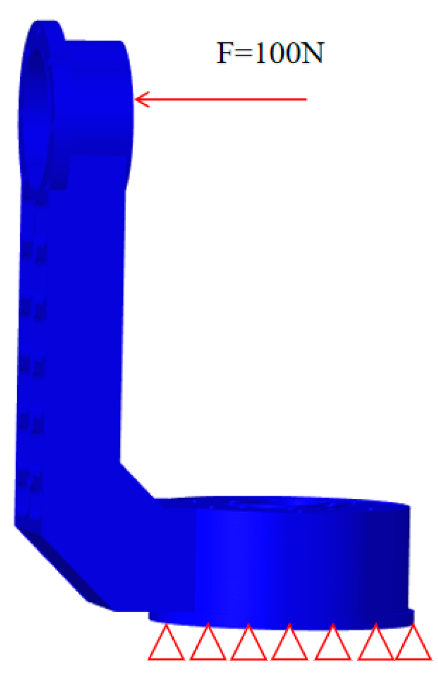
Figure 4.
Finite element mesh division of the initial design of the bracket structure for the acquisition, pointing, and tracking system.
Figure 4.
Finite element mesh division of the initial design of the bracket structure for the acquisition, pointing, and tracking system.
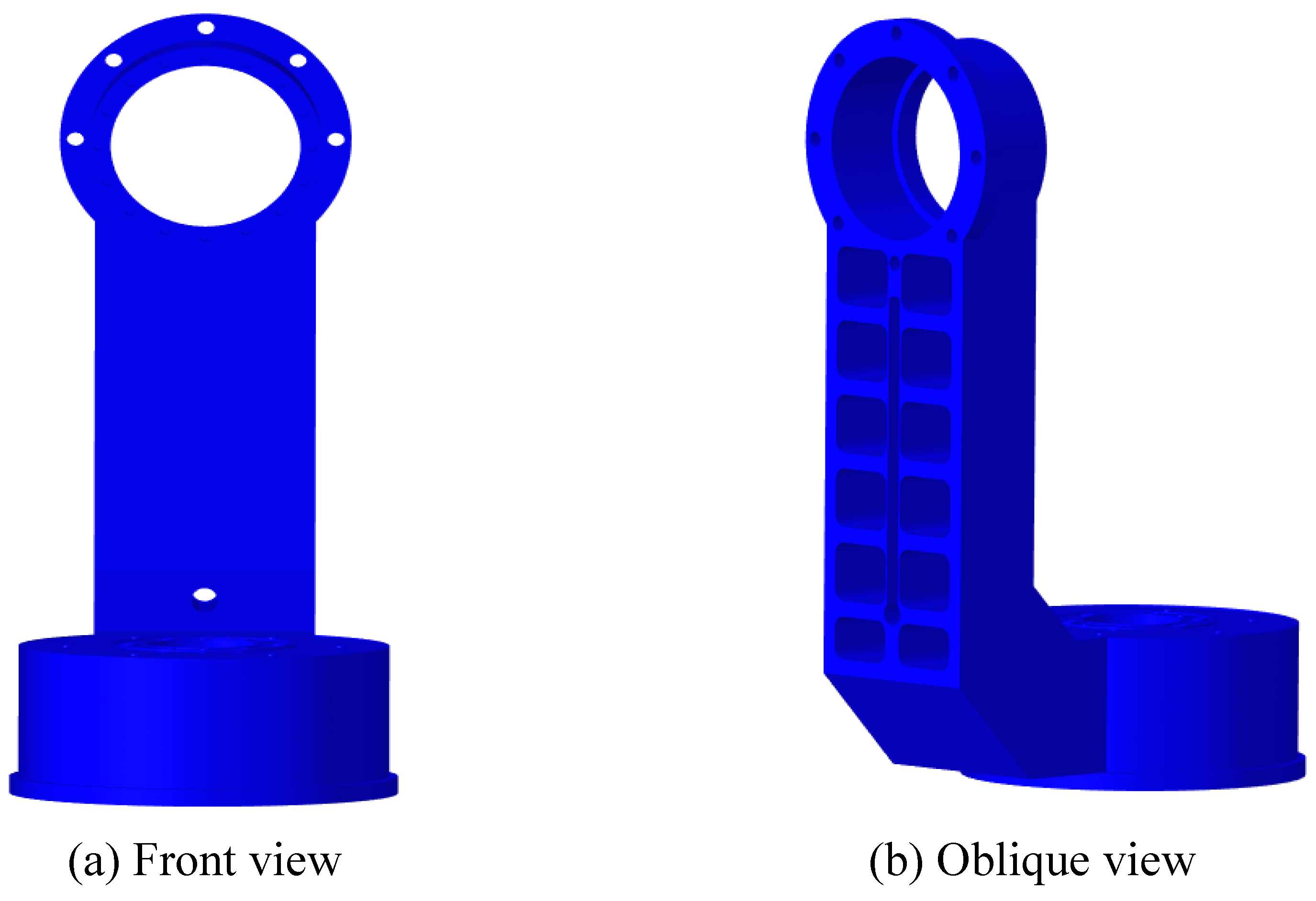
Figure 5.
Static analysis results of the collection, pointing, and tracking system support structure.
Figure 5.
Static analysis results of the collection, pointing, and tracking system support structure.
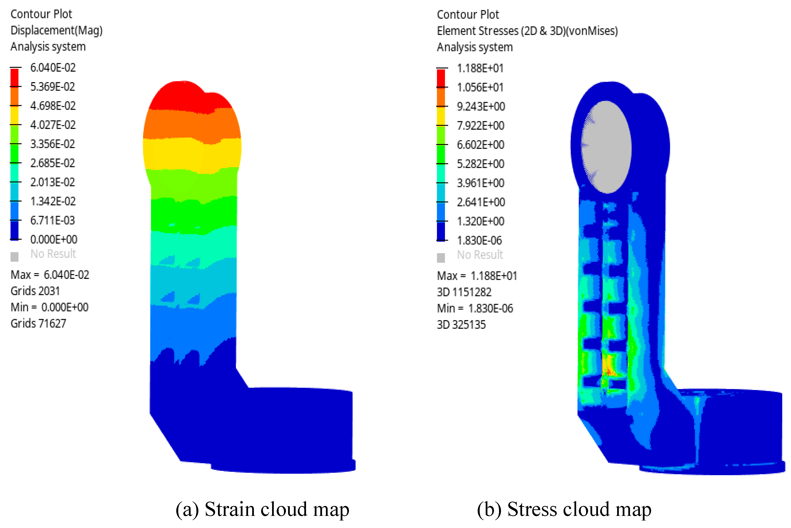
Figure 6.
The front and oblique view of the APTS’ bracket structure.
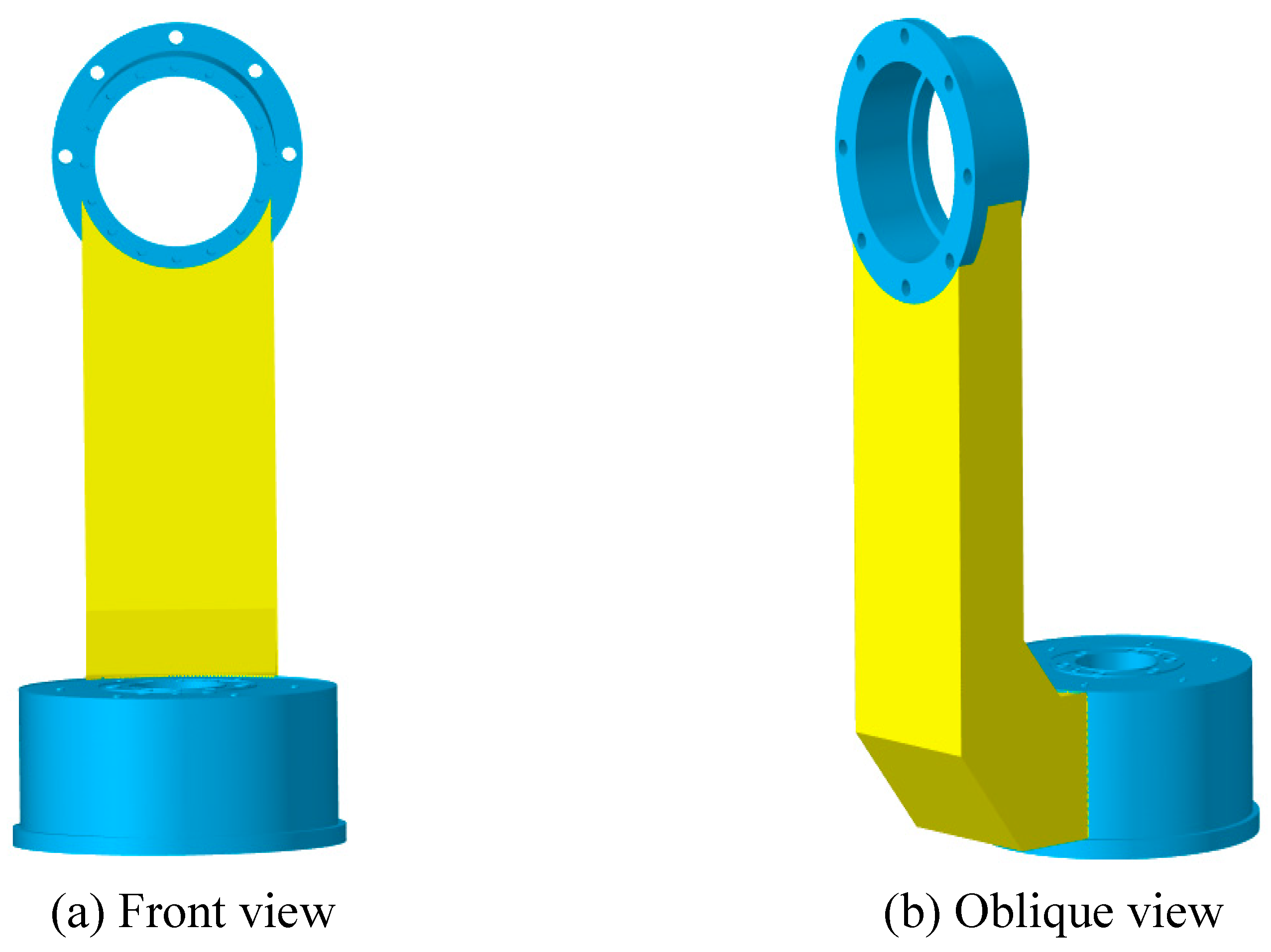
Figure 7.
Schematic diagram of boundary conditions and loads for the optimization model.
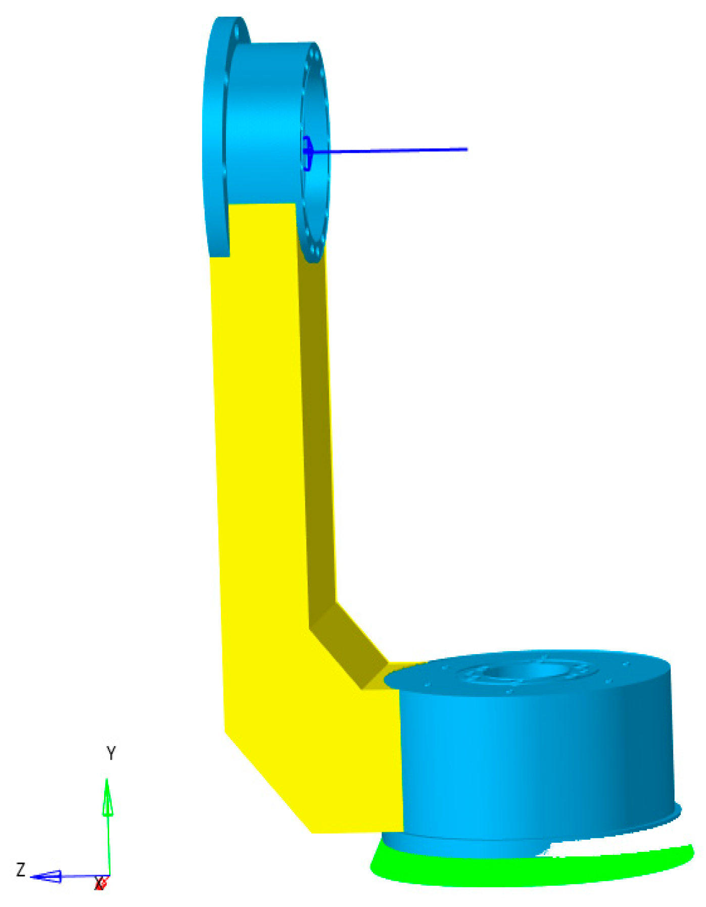
Figure 8.
The optimized topology configurations of the APTS’ L-shaped bracket structure with displacement and stress constraints.
Figure 8.
The optimized topology configurations of the APTS’ L-shaped bracket structure with displacement and stress constraints.
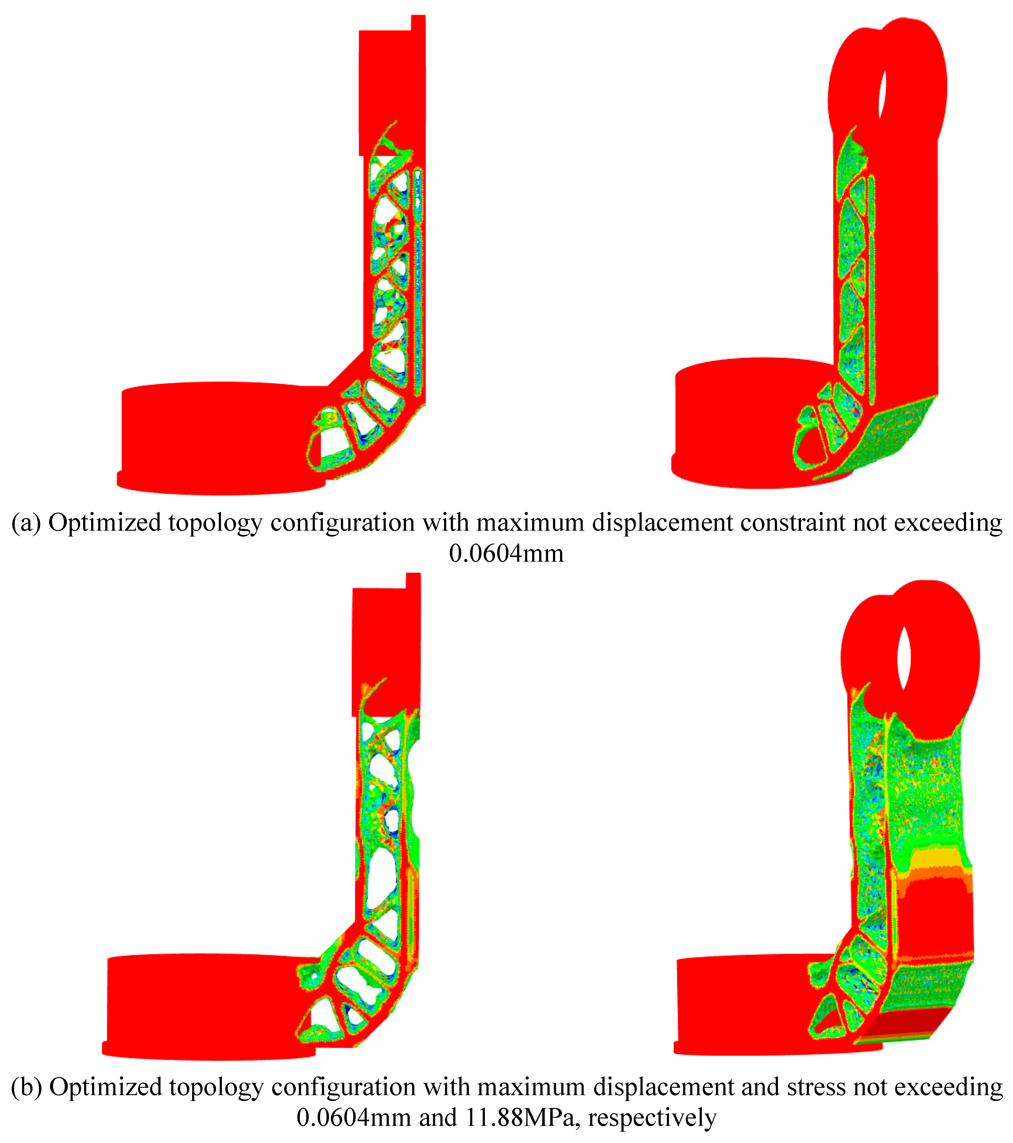
Figure 9.
Volume iteration history of the APTS’ L-shaped bracket structure with displacement and stress constraints.
Figure 9.
Volume iteration history of the APTS’ L-shaped bracket structure with displacement and stress constraints.
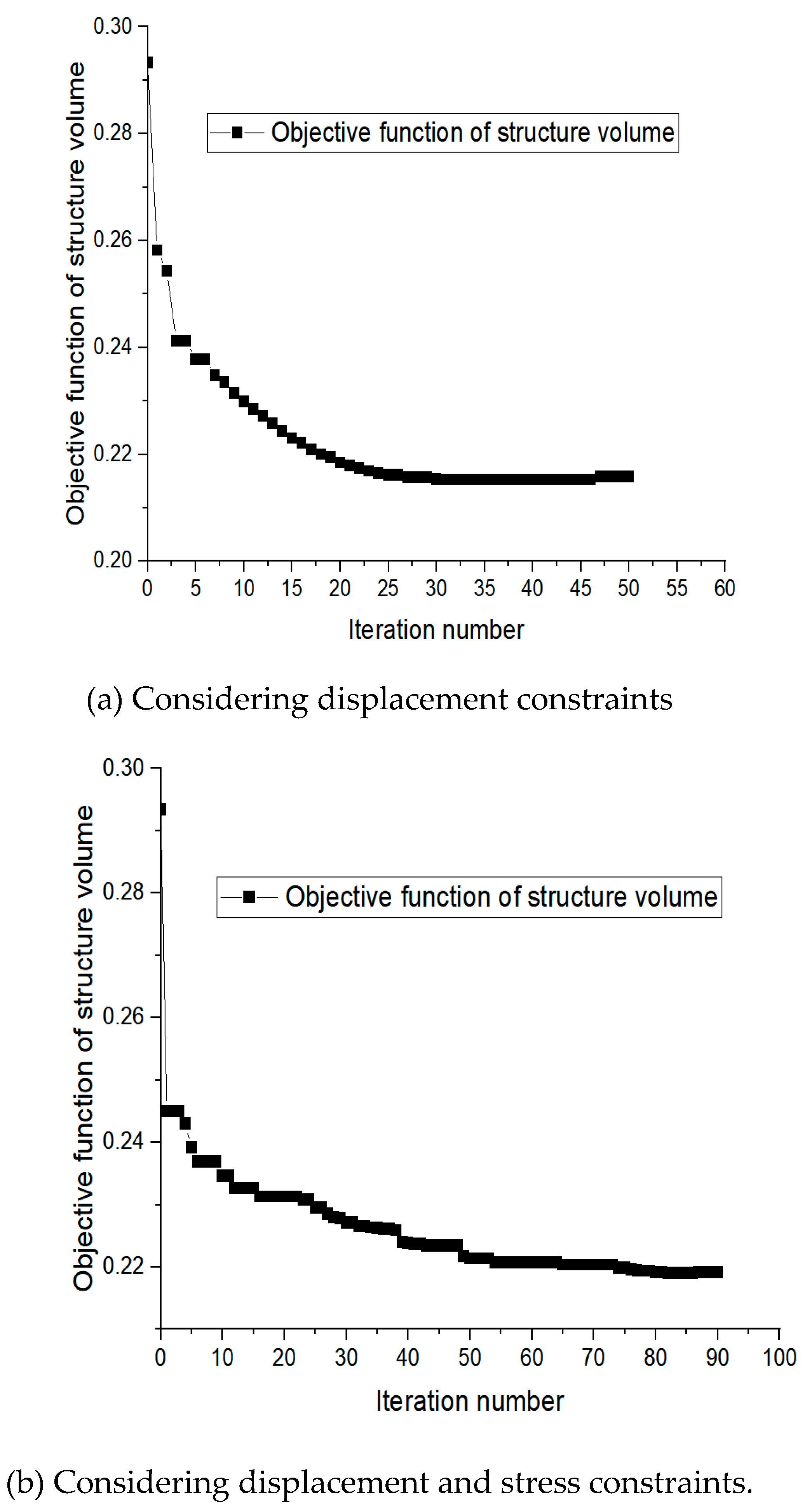
Figure 10.
The optimized topology configurations of the APTS’ L-shaped bracket structure for minimizing compliance considering volume fraction constraints.
Figure 10.
The optimized topology configurations of the APTS’ L-shaped bracket structure for minimizing compliance considering volume fraction constraints.
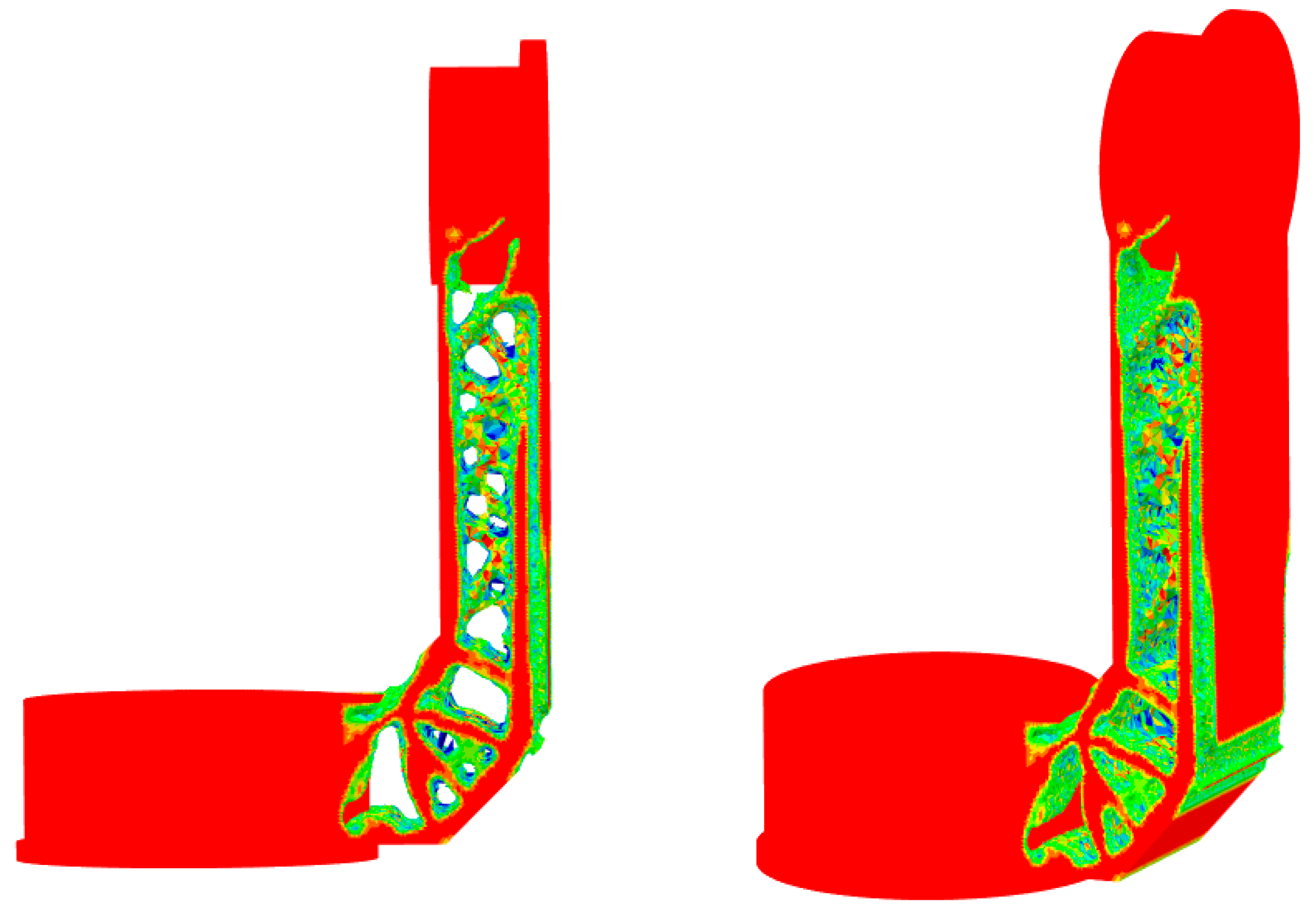
Figure 11.
Volume iteration history of the APTS’ L-shaped bracket structure for minimizing compliance considering volume fraction constraints.
Figure 11.
Volume iteration history of the APTS’ L-shaped bracket structure for minimizing compliance considering volume fraction constraints.
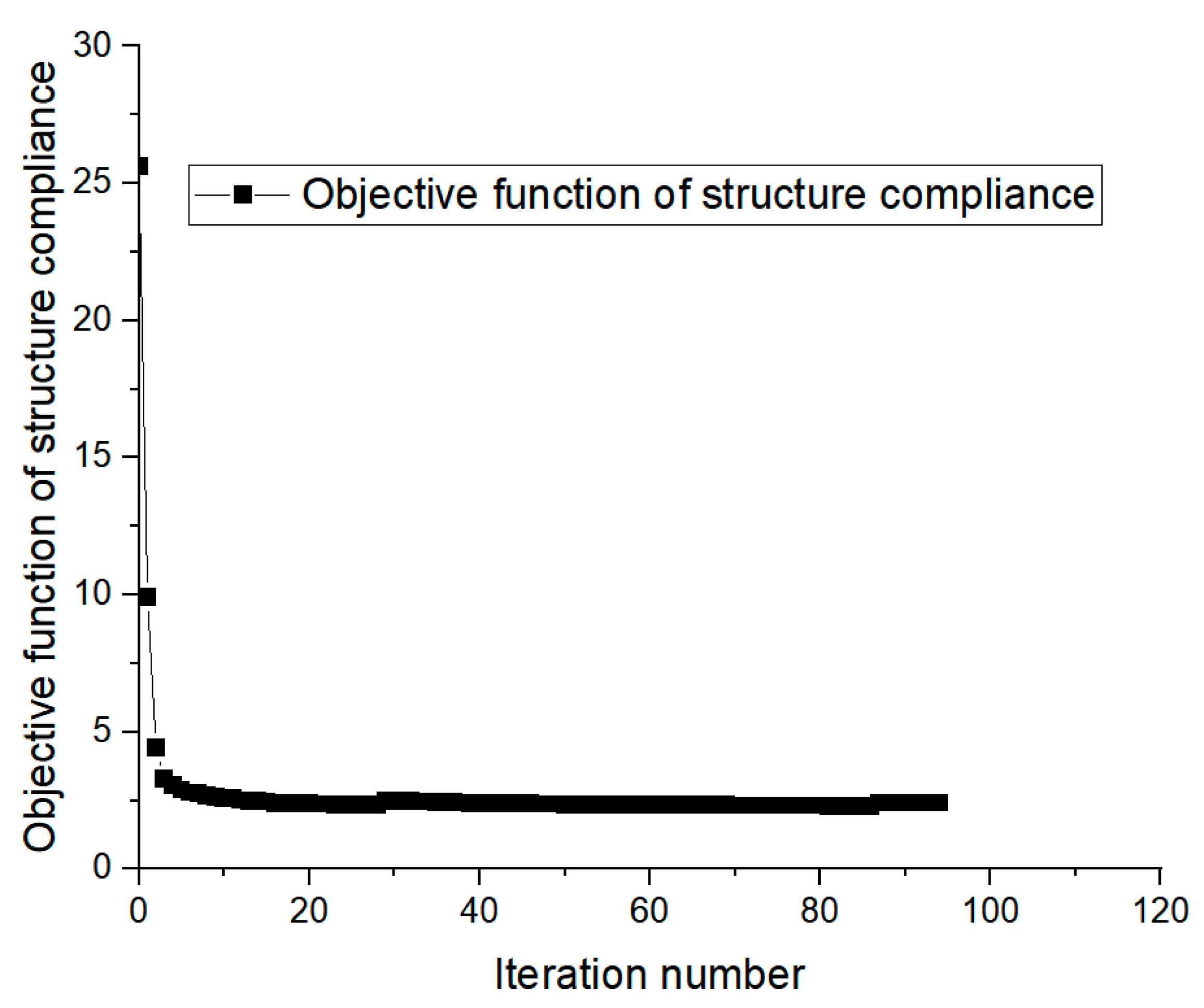
Figure 14.
Verification cloud map for the optimized structure considering displacement and stress constraints.
Figure 14.
Verification cloud map for the optimized structure considering displacement and stress constraints.
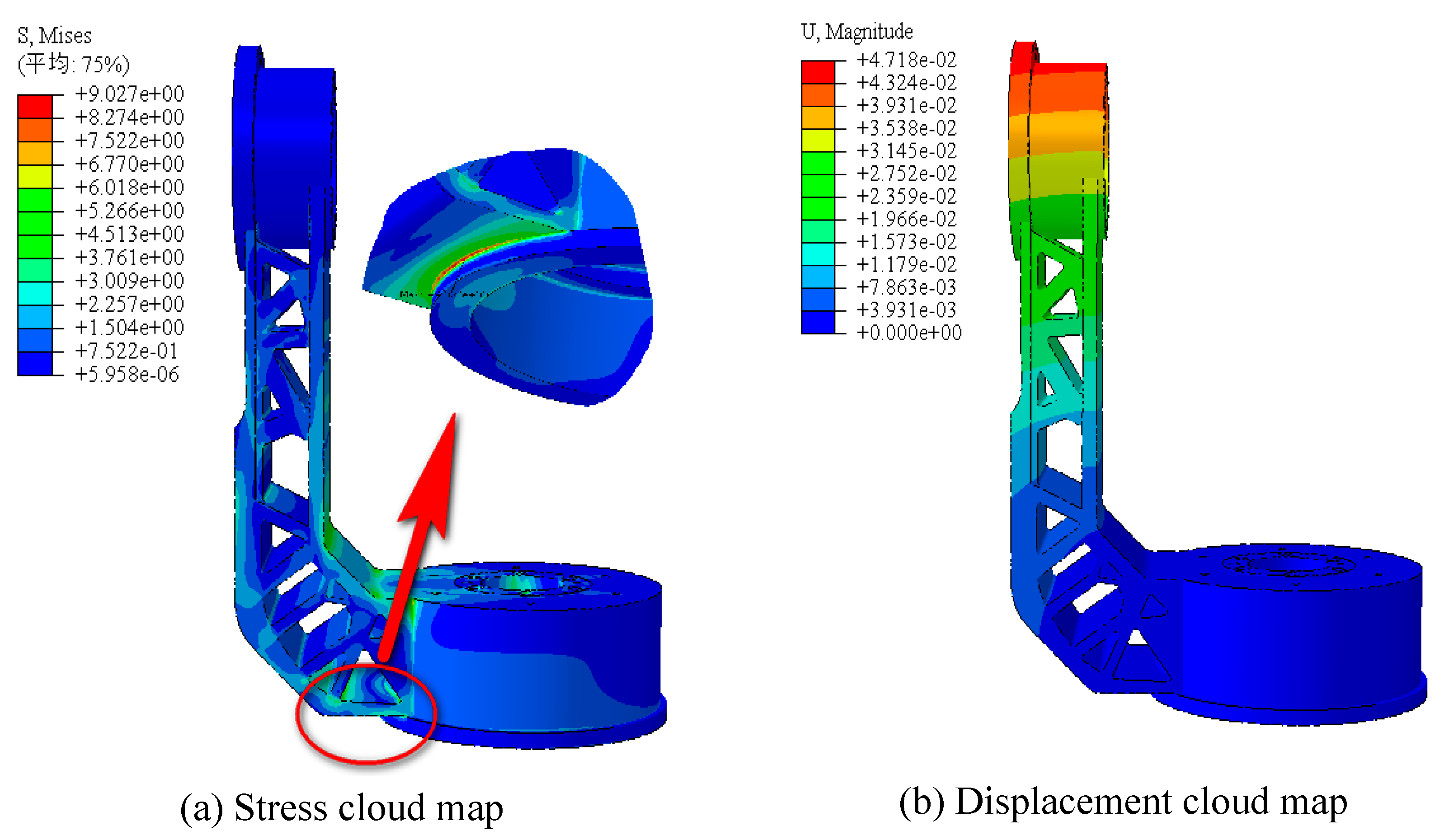
Figure 15.
Verification cloud map for compliance minimization for the optimized structure considering volume fraction constraints.
Figure 15.
Verification cloud map for compliance minimization for the optimized structure considering volume fraction constraints.
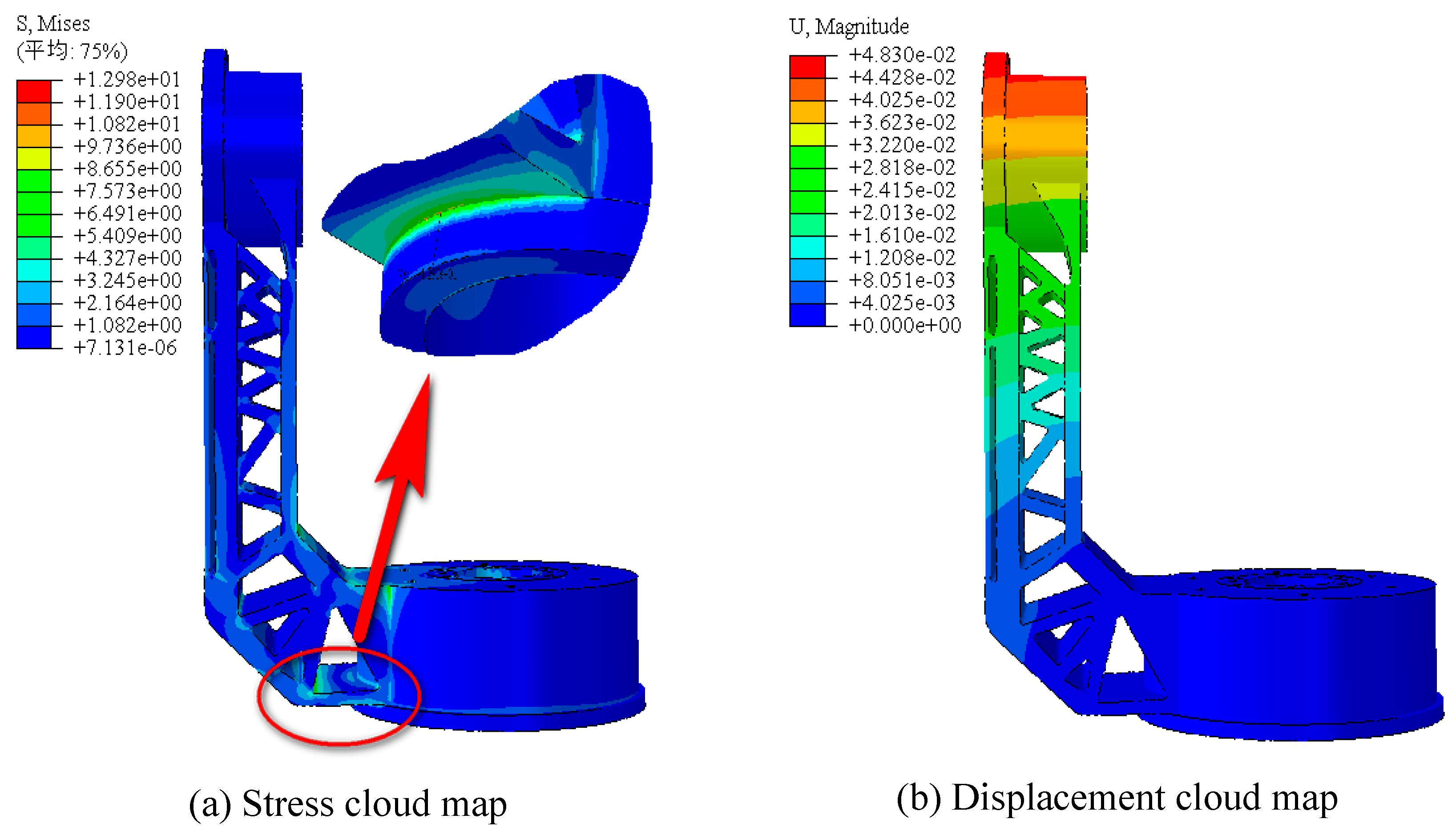

Table 1.
Summary of Optimization Results.
| Objective function | Maximum displacement/mm | Maximum von Mises stress/MPa | Weight/kg |
| Minimize volume (with displacement constraints) | 0.04420 | 11.81 | 0.648 |
| Minimize volume (with displacement and stress constraints) | 0.04718 | 9.027 | 0.635 |
| Minimize compliance | 0.04830 | 12.98 | 0.655 |
Disclaimer/Publisher’s Note: The statements, opinions and data contained in all publications are solely those of the individual author(s) and contributor(s) and not of MDPI and/or the editor(s). MDPI and/or the editor(s) disclaim responsibility for any injury to people or property resulting from any ideas, methods, instructions or products referred to in the content. |
© 2024 by the authors. Licensee MDPI, Basel, Switzerland. This article is an open access article distributed under the terms and conditions of the Creative Commons Attribution (CC BY) license (http://creativecommons.org/licenses/by/4.0/).
Copyright: This open access article is published under a Creative Commons CC BY 4.0 license, which permit the free download, distribution, and reuse, provided that the author and preprint are cited in any reuse.


