Submitted:
14 October 2024
Posted:
15 October 2024
You are already at the latest version
Abstract
The permeation of tritium from secondary neutron source rods in nuclear power plants presents a significant and unavoidable safety concern for both internal equipment and the external environment. This study primarily explores two feasible strategies for tritium permeation barriers: coating stainless steel surfaces with tritium-permeation-barrier (TPB) materials and utilizing materials with excellent tritium absorption properties. Through external ion irradiation tests, a comparative analysis was conducted on the tritium permeation performance, microstructure, and nano-hardness changes of two tritium-resistant designs, specifically Cr2O3/Al2O3 composite coatings, and a zirconium-based tritium-absorbing material under varying irradiation doses. The results indicate that both approaches exhibit exceptional radiation resistance, maintaining an effective tritium permeation reduction factor (PRF) even after irradiation.
Keywords:
tritium-permeation-barrier (TPB)
; irradiation
; permeation reduction factor (PRF)
1. Introduction
In pressurized water reactor (PWR) nuclear power plants, the secondary neutron source (Sb-Be) produces tritium after irradiation [1]. Tritium is radioactive and highly permeable, posing significant hazards to operators and the environment by contaminating reactor coolant and leading to hydrogen embrittlement of structural materials. Controlling tritium permeation and leakage is an essential issue in evaluating the radiation environment in PWRs.
Tritium formation in secondary neutron source rods mainly occurs through three reactions, with the primary reaction occurring during reactor operation, as shown in Figure 1. For a 900 MW power plant [2] with a neutron flux of 3.5×10¹⁴ n·cm-2·s-1 and neutron energy E ≥ 0.625 eV, each gram of Be in the core can produce approximately 2.47×10¹² atoms/s, including 2.30×10¹² helium atoms and 1.7×10¹¹ tritium atoms. Assuming all tritium remains in the rod, at the end of the secondary neutron source component's lifetime, the partial pressures of helium and tritium inside the rod could reach around 7 MPa and 0.5 MPa, respectively. However, in reality, the Sb-Be core cannot retain tritium, and the stainless steel cladding currently used allows high tritium permeability, leading to nearly all tritium produced by the Sb-Be core entering the coolant [3]. In French 1300 MW and 1450 MW nuclear power plants, tritium from the secondary neutron source components accounts for about 20-40% of the tritium in the primary coolant system [4]. Around 2000, the tritium produced by secondary neutron sources at Daya Bay accounted for approximately 10-20% of the annual emissions. Abnormal axial power shifts (AOA) in the core can also increase tritium production in secondary neutron source rods, as the axial power peak shifts towards the bottom, where the secondary neutron sources are located, resulting in increased tritium generation proportional to the neutron flux in the core. Implementing effective measures to trap tritium within the secondary neutron source rods is a viable strategy to reduce tritium release.
Tritium permeates by diffusion in the form of interstitial atoms and is able to pass through almost all metals with high permeability. Tritium permeability increases with increasing temperature and neutron flux. The permeability of hydrogen isotopes (hydrogen, deuterium, and tritium) in stainless steel at temperatures greater than 400℃ is 2 to 3 orders of magnitude higher than at room temperature. In addition, the permeability of stainless steel under irradiation in the reactor will be higher than that measured under the same temperature and pressure conditions in off-heap tests. For example, experimental results for 304 stainless steel indicate that at 570 °C, the permeability under irradiation conditions is three times higher than that under non-irradiation conditions [5]. The slow growth of the oxide layer on the surface of stainless steel will lead to a decrease in permeability. For example, under irradiation conditions, a 0.01 vol.% oxide layer on 0.12C-18Cr-10Ni-Ti can reduce its permeability by around 100 times [6]. The permeability of 316 stainless steel inside the stack is approximately 2 to 5 times higher than the permeability measured in external tests [7].
Coating structural materials with a TPB layer of sufficient thickness, low tritium diffusion coefficient, and low surface recombination constant is one of the most effective practical methods to reduce tritium permeation while preserving the overall properties of the structural materials. The tritium permeation capability of a coating is generally evaluated using the PRF (tritium permeation reduction factor), defined as the ratio of tritium permeability in the substrate material to that in the coated substrate. A higher PRF indicates stronger tritium-permeation resistance. Al2O3 coatings are considered important candidates for tritium-permeation barriers due to their high PRF (up to 2-4 orders of magnitude) [8], ease of preparation, and corrosion resistance. However, differences in thermal expansion coefficients between the substrate and coating materials can cause aluminum oxide coatings to peel off, posing a significant technical challenge. This can be addressed using composite coatings (e.g., Al2O3/FeAl, Al2O3/TiC, Al2O3/Cr2O3, Al2O3/SiC, Al2O3/TiB2), which improve adhesion to the substrate, provide effective stress relief, and exhibit self-healing capabilities for microcracks. These enhancements increase the coating's resistance to spalling and introduce tritium diffusion traps, thereby improving tritium permeation resistance.
Aluminide coatings have been widely used as anti-corrosion coatings in conventional industries and the preparation techniques are well established. K. Stein [9] prepared aluminide coatings on MANETs using the liquid hot dip aluminium technique to prepare aluminising coatings on MANET, obtaining hydrogen PRFs of 260-1000 at 300-470 °C. Benamatic [10] prepared aluminized coatings on MANET using solid aluminizing technique and obtained hydrogen PRF of 2500~5000 °C in 400~500 °C. Fazio [11] prepared aluminide coatings on MANET surfaces using spraying, low pressure plasma sputtering, and air plasma sputtering, respectively, with hydrogen PRFs of 1-3 orders of magnitude in the range of 350-500 °C. A. Perujo [12] prepared aluminide coatings on MAET II using vacuum plasma sputtering with hydrogen PRFs of 2-3 orders of magnitude at 300~550 °C. Forcey [10] prepared aluminide coatings on 316L and DIN 1.4914 by solid aluminising and obtained hydrogen PRFs of 2-4 orders of magnitude at 300~500 °C. Liu Xingzhao [13] obtained PRFs of 300~400 after TiN plating on HR-1 by CVD. Forcey [8] prepared TiN/TiC and Al2O3/TiN/TiC composite coatings on 316L surface by CVD method and found that the PRF of deuterium is only one order of magnitude at 250~450 °C. While Shang Changqi [14] found the PRFs of TiC monolayer film and TiN+TiC composite film prepared on 316L surface by CVD method are 5~6 orders of magnitude at 200~600 °C. Yao Zhenyu [15] prepared TiN+TiC+TiN and TiN+TiC+SiO₂ composite films on 316L stainless steel, wthch have the PRF of 4~5 and 4~6 orders of magnitude respectively at 200~600 °C, using the physical vapor deposition (PVD) method.
Zirconium-based alloys are also widely used in hydrogen storage and purification systems due to their strong affinity for tritium. Tritium formed from fuel fission is nearly entirely sealed in the fuel cladding as hydride, with only about 0.01% of tritium eventually leaking from nuclear power plants [4]. Studies by Song Jiangfeng et al [16] showed that Zr2Fe alloy powder has a hydrogen absorption capacity of about 32% under 300°C and 1 bar conditions with a 2.5% H2/Ar mixture. In 2000, the US Department of Energy designed a Tritium Producing Burnable Absorber Rod (TPBAR) using zirconium alloys as tritium-absorbing materials in 17×17 fuel assemblies [17]. However, mature studies on the use of treated zirconium-based alloys as secondary neutron source tritium barriers in PWR environments are lacking. The impact of irradiation dose on the tritium-permeation performance of coatings or zirconium-based alloys, given the long service time of secondary source rods in reactors, is crucial for their application.
This study evaluates and selects tritium-permeation barriers with excellent performance through a series of tests on Cr2O3/Al2O3 coatings and zirconia. It examines the tritium-permeation performance of 316L stainless steel Cr2O3/Al2O3 coatings and zirconium alloy self-oxidation films before and after irradiation. The influence of factors such as irradiation, temperature, and deuterium partial pressure on the tritium-permeation performance of the coatings and oxidation films is assessed. Based on experimental results, the tritium-permeation behavior of coated stainless steel tubes and pre-oxidized zirconium alloy tubes is simulated, identifying key factors affecting the materials' tritium-permeation resistance.
2. Experimental Methods
2.1. Irradiation Tests
The tests primarily used an HVE 3MV tandem accelerator. Gold ions were chosen for irradiation because they are chemically inert and do not react with the material. Additionally, the concentration distribution and damage region of gold ions differ slightly near the surface, causing minimal impact on material composition. Using ions like Fe or Al, which are present in the material, for irradiation would interfere with microstructure and composition analysis and have a more significant impact on the material's phase structure, differing from actual neutron irradiation conditions, thereby not effectively simulating or evaluating the impact of neutron irradiation damage on the coatings, the test parameters are shown in Table 1.
2.2. Gas Hydrogen Isotope Permeation (GDP) Test
Deuterium is used for permeation experiments. The structure of the experimental device used in this experiment is shown in Figure 2.
The deuterium permeation test conditions for the coatings after irradiation are shown in Table 2. At least one sample of each coating type is prepared for the permeation test under each set of irradiation parameters.
2.3. Microstructure Inspection
Microstructural analysis of the specimens before and after irradiation was carried out using FIB/TEM or SEM techniques. By correlating the lattice parameters, the information regarding dislocation densities was obtained, and precipitated phase structures, pore morphology, pore size distributions, and the total number of pores of each sample were counted within the measurement ranges.
FIB sample preparation was conducted using the FEI Helios NanoLab 600i equipment. The typical thickness of samples prepared by FIB is around 5 μm. The two advanced TEM devices FEI Talos F200X and FEI Tecnai G2 F20 were used to the microstructural analysis. To mitigate the risk of sample damage due to traditional mechanical polishing, all specimens intended for TEM analysis were prepared using FIB milling techniques, ensuring the samples met the required criteria for TEM examination.
The two TME devices were also employed to conduct high-resolution and selected area electron diffraction (SAED) analyses. These techniques enabled an in-depth characterization of the microstructure of irradiated coatings. The analyses provided detailed insights into features such as dislocations, phase distributions, and crystallographic orientations post-irradiation, thereby allowing for a comprehensive understanding of the material's properties and behaviors under irradiation conditions.
The surface and cross-section microstructure or topography of some samples were characterized using a field emission scanning electron microscope (FEEM) model Thermo Scientific Apreo 2c.
2.4. Nanoindentation Inspection
Nanoindentation tests were conducted on the samples before and after irradiation to assess the impact of irradiation on the mechanical properties of the coatings, specifically focusing on adhesion performance. the Nano Indenter G200 (Agilent Technologies Inc., Santa Clara, CA, USA) was used.The indenter used for the tests was a Berkovich diamond tip. The nanoindentation experiments employed two modes: Continuous Stiffness Measurement (CSM) and static mode.
The calculation of nanohardness was based on the Oliver-Pharr method, which allows for the determination of hardness and elastic modulus from the load-displacement data collected during the indentation process. To ensure the reliability and accuracy of the experimental results, each sample underwent multiple measurements (≥3 times) to assess the nanohardness values. This systematic approach helped to evaluate the impact of irradiation on the mechanical properties, particularly the adhesion strength of the coatings.
3. Results and Discussion
3.1. Cr2O3/Al2O3 Coating on Stainless Steel Surface
Figure 3 shows the deuterium permeation test curves of Cr2O3/Al2O3 composite coating after 10 dpa, 30 dpa, and 50 dpa irradiation. The test conditions are the same as those of the unirradiated samples. As seen in the figure, the deuterium permeation signal of the Cr2O3/Al2O3 composite coating increases initially and then decreases with the increase of irradiation damage. The deuterium permeation signal of the Cr2O3/Al2O3 composite coating at 10 dpa and 50 dpa irradiation damage is lower than that of the unirradiated samples, and the change in deuterium permeation signal is not significant as the temperature decreases. The deuterium permeation signal of the composite coating with 30 dpa irradiation damage is significantly higher than that of the unirradiated samples at 500 °C, and decreases with the reduction in test temperature, becoming similar to the irradiated samples at 400 °C.
Using FIB, the cross-section of the Cr2O3/Al2O3 composite coating was obtained, as shown in Figure 4(a-c), which display the cross-sectional microstructure of the Cr2O3/Al2O3 composite coating. The Cr2O3/Al2O3 composite oxide layer exhibits good adhesion, with a uniform structural distribution within a certain depth range (~1.5 μm) on the surface layer. The composite coating is ~1.5 μm thick, with two interfacial structures: one between the substrate and Cr2O3, and the other between Cr2O3 and Al2O3. Under all three irradiation conditions, crystal grain swelling occurs inside the outer Al2O3 coating, intensifying with increasing irradiation dose.
Figure 5 and Figure 6 show the surface SEM and EDS of the Cr2O3/Al2O3 composite coating after irradiation. EDS data indicate that the bi-layer structure remains intact after irradiation, with Al, Cr, and O atoms uniformly distributed across the coating cross-section, demonstrating good radiation resistance. The atomic content of Al, Cr, and O does not significantly change with increasing irradiation dose. SEM analysis reveals that the surface of the composite coating develops a few grooves after 10 dpa irradiation and pores after 50 dpa irradiation, with increased roughness. Combined with the cross-sectional analysis, it is evident that as the irradiation dose increases, the size and density of irradiation voids increase, leading to more defects in the composite coating. At 50 dpa irradiation, significant erosion marks appear on the surface. It is also notable that with increasing irradiation dose, the degree of swelling at the bi-layer interface of the composite coating increases. Since the composite coating interface is an effective hydrogen permeation coating, the change in deuterium permeation performance after irradiation is related to the bi-layer interface. The composite coating still demonstrates good hydrogen permeation resistance under 30 dpa irradiation.
Figure 7 shows the TEM cross-section images and SAED patterns of the irradiated coating samples. The outer layer consists of a disordered arrangement of Cr and O atoms, with the electron diffraction pattern showing severe ring dispersion, indicating a completely amorphous structure of the Cr2O3 outer layer. The inner coating consists of Al and O atoms, forming ring patterns indicative of a crystalline Al2O3 structure.
3.2. Pre-oxidized Zirconium Alloy
Figure 8 shows the deuterium permeation test curves of pre-oxidized zirconium alloy after 10 dpa, 30 dpa, and 50 dpa irradiation. The test conditions are the same as those for the unirradiated samples. As shown in the figure, the deuterium permeation signal of the oxide film with 10 dpa irradiation damage increases significantly, and decreases with the reduction in test temperature, being nearly an order of magnitude lower than that of the unirradiated sample at 400 °C. The deuterium permeation signal of the oxide film with 30 dpa irradiation damage increases slightly at 500 °C and decreases with the reduction in test temperature, being lower than that of the unirradiated sample at 450 °C and 400 °C. The deuterium permeation signal of the oxide film with 50 dpa irradiation damage is higher than that of the unirradiated sample at 500 °C but lower than that of the 10 dpa irradiated sample, and decreases with the reduction in temperature, being nearly the same as the unirradiated sample at 450 °C and slightly lower at 400 °C.
Using FIB, the cross-sectional microstructure of the irradiated pre-oxidation film was obtained, as shown in Figure 9. The oxide layer exhibits good adhesion to the zirconium substrate, with a uniform structural distribution in the pre-oxidation film (~1.7 μm).
Figure 10 and Figure 11 show the surface SEM and EDS of the pre-oxidation coating. The content of O and Zr elements on the surface of the coating does not change significantly with increasing irradiation dose, compared to the original coating surface, with a slight decrease (2~3%). This indicates that the structure of the oxidation film remains unchanged after irradiation. It is noteworthy that the coating thickness of the 10 dpa irradiated sample is only 1.2 μm, while the thickness of the 30 dpa and 50 dpa samples is nearly the same, indicating a reduction in the thickness of the oxidation film after irradiation. The 10 dpa oxidation film exhibits the largest reduction in thickness, while the 30 dpa and 50 dpa samples have higher thicknesses than the 10 dpa irradiated sample. The oxidation film formed after irradiation appears denser and smoother compared to the 10 dpa and unirradiated samples. This difference explains the different permeation curves observed for the 10 dpa, 30 dpa, and 50 dpa irradiated samples, with the 30 dpa and 50 dpa oxidation films exhibiting surface-controlled permeation and the 10 dpa sample exhibiting diffusion-controlled permeation.
The composition of the pre-oxidation film was characterized using the EDS module, as shown in Figure 11. The O and Zr elements are uniformly distributed across the coating cross-section under different irradiation doses, indicating a dense ZrO2 layer.
Figure 12 shows the TEM cross-section images and SAED patterns of the irradiated coating samples. Structural changes within the pre-oxidation film were observed with increasing irradiation dose, confirming the growth of the oxidation film during irradiation.
4. Conclusions
The tritium permeation performance and potential mechanisms of Cr2O3/Al2O3 composite coating on stainless steel and pre-oxidized zirconium alloy under different irradiation doses were compared in this study. The conclusions are as follows:
- For Cr2O3/Al2O3 composite coating, the tritium permeation resistance decreases by approximately three times at 30 dpa but slightly improves at lower and higher irradiation doses (10 dpa and 50 dpa). The microstructure of the coating deteriorates after irradiation, with increasing defects within the layers and at the interfaces with increasing irradiation dose. These defects may increase deuterium trapping sites, slightly improving tritium permeation resistance at high irradiation doses.
- For pre-oxidized zirconium alloy, the tritium permeation resistance shows little change after 10 dpa, 30 dpa, and 50 dpa irradiation. The surface microstructure of the oxidation film remains unchanged after irradiation, but structural transformations occur within the film with increasing irradiation dose.
Despite the observed irradiation defects in the Cr2O3/Al2O3 composite coating and the pre-oxidized zirconium alloy under high-dose irradiation environments, the two kinds of tritium barriers can still keep certain tritium permeation resistance. This provides the reference basis for the tritium barrier application design and serves as a candidate scheme for subsequent engineering applications. If further engineering implementation is carried out, neutron irradiation tests in experimental reactors are still needed to verify the design and process stability.
References
- Fu, Y.; Li,H. ; Li,H. Main Low Energy β Emitter Radioactivity and Control Method Research in Nuclear Power Plant. Nucl. Sci. Technol. 2021, 3, 9–15. (in Chinese). [Google Scholar] [CrossRef]
- SHAN Chen-yu, SHI Xiu-an, CAI De-chang, HAN Song, LI Lei. Analysis and calculation of annual emission of tritium for daya bay and ling ao nuclear power plant. Nuclear Science and Engineering 2013, 33. (in Chinese). [Google Scholar]
- Kim, B.; Love, B.; Elmore, M. Tritium Production in Secondary Neutron Sources in Pressurized Water Reactors, Fusion Sci. Technol. 2016, 71, 544–548. [Google Scholar]
- Ma Yong, Wang Zhaogui. Management of tritium-containing waste from EDF NPPs. Daya Bay Nuclear Power 2012, 3. (in Chinese).
- Polosukhin, B.G.; Menkin, L.I. An interaction of hydrogen isotopes with austenic Cr-Ni steels without and during reactor irradiation. Hydrogen Recycle At Plasma Facing Materials, 1st ed. Wu, C.H., Ed.; Springer: Dordrecht, 2000; 133–140. [Google Scholar]
- Gautsch O, Hoddap G. Deuterium permeability of the austenitic stainless steel AISI 316. Journal of Nuclear Materials, 1988, 152, 35–40. [Google Scholar] [CrossRef]
- Le Claire, A.D. Permeation of hydrogen isotopes in structural alloys. J. Nucl. Mater. 1984, 122–123, 1558–1559. [Google Scholar] [CrossRef]
- Forcey, K. S.; Rose, D.K.; Wu, C.H. The formation of hydrogen permeation barriers on steels by aluminising. J. Nucl. Mater. 1991, 182, 36–51. [Google Scholar] [CrossRef]
- Stein-Fechner K, Konys J, Wedemeyer O. Investigations on the transformation behavior of the intermetallic phase (Fe, Cr) 2Al5 formed on MANET II steel by aluminizing. Journal of nuclear materials, 1997, 249, 33–38. [Google Scholar] [CrossRef]
- Benamati G, Chabrol C, Perujo A, et al. Development of tritium permeation barriers on Al base in Europe. Journal of Nuclear Materials, 1999, 271, 391–395. [Google Scholar]
- Fazio C, Benamati G, Martini C, et al. Compatibility tests on steels in molten lead and lead–bismuth. Journal of nuclear materials, 2001, 296, 243–248. [Google Scholar] [CrossRef]
- Perujo A, Serra E, Kolbe H, et al. Hydrogen permeation rate reduction by post-oxidation of aluminide coatings on DIN 1.4914 martensitic steel (MANET). Journal of nuclear materials, 1996, 233, 1102–1106. [Google Scholar]
- Liu, X.; Huang, Q. ; Study on hydrogen permeation of HR-1 austenitic stainless steel coated with Cr2O3 and TiN films. Nucl. Sci. Eng. 1997, 17, 281–284. (in chinese). [Google Scholar]
- Shang, C.; Wu, A.; Li, Y.; Zhao, Z.; Chen, Q.; Huang, Q.; Shi, S. The behaviour of diffusion and permeation of tritium through 316L stainless steel with coating of TiC and TiN+TiC. J. Nucl. Mater. 1992, 191–194, 221–225. [Google Scholar] [CrossRef]
- Yao, Z. Study on anti-tritium penetration performance of different coatings on cladding materials of fusion reactor. Master's thesis, China institute of atomic energy, Beijing China, 2001. [Google Scholar]
- Song, J.; Wang, J.; Jiang, F.; Li, P.; Zhu, Z.; Meng, D. Experiment and simulation on Zr2Fe bed for tritium capturing, RSC Adv. RSC Adv. 2019; 9, 1472–1475. [Google Scholar]
- Burns, K.A.; Love, E.F.; Thornhill, C.K. Description of the Tritium-producing Burnable Absorber Rod for the Commercial Light Water Reactor TTQP-1-015, 7th ed. Pacific Northwest National Laboratory: USA, 2012. [Google Scholar]
Figure 1.
Equations for tritium generation in the secondary neutron source rod.
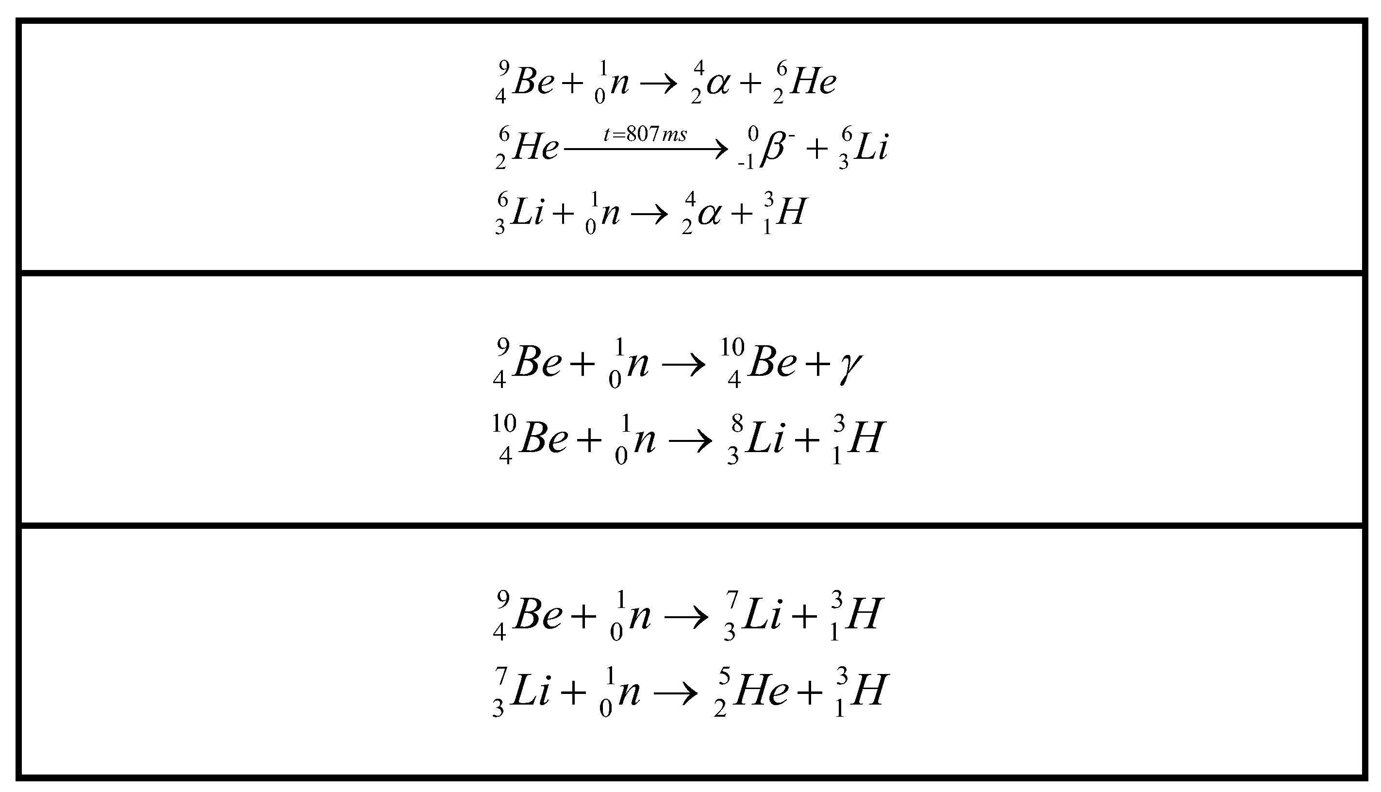
Figure 2.
Schematic diagram of deuterium permeation testing system: 1-Sample, 2-Furnace, 3-Standard Leak, 4-Ultra-high Vacuum System, 5-Mechanical Pump, 6-High Vacuum System, 7-Mechanical Pump, 9~10-Gas Cylinder, V1~9-Valves.
Figure 2.
Schematic diagram of deuterium permeation testing system: 1-Sample, 2-Furnace, 3-Standard Leak, 4-Ultra-high Vacuum System, 5-Mechanical Pump, 6-High Vacuum System, 7-Mechanical Pump, 9~10-Gas Cylinder, V1~9-Valves.
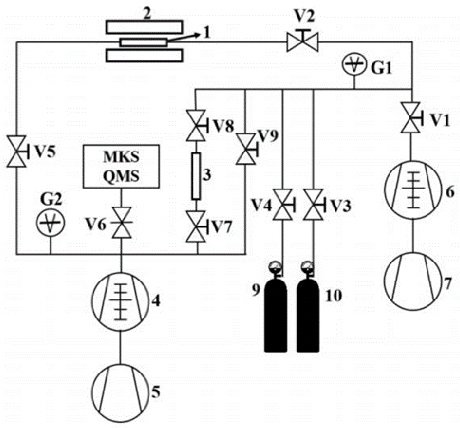
Figure 3.
Deuterium permeation curve of Cr2O3/Al2O3 composition coating after irradiation.
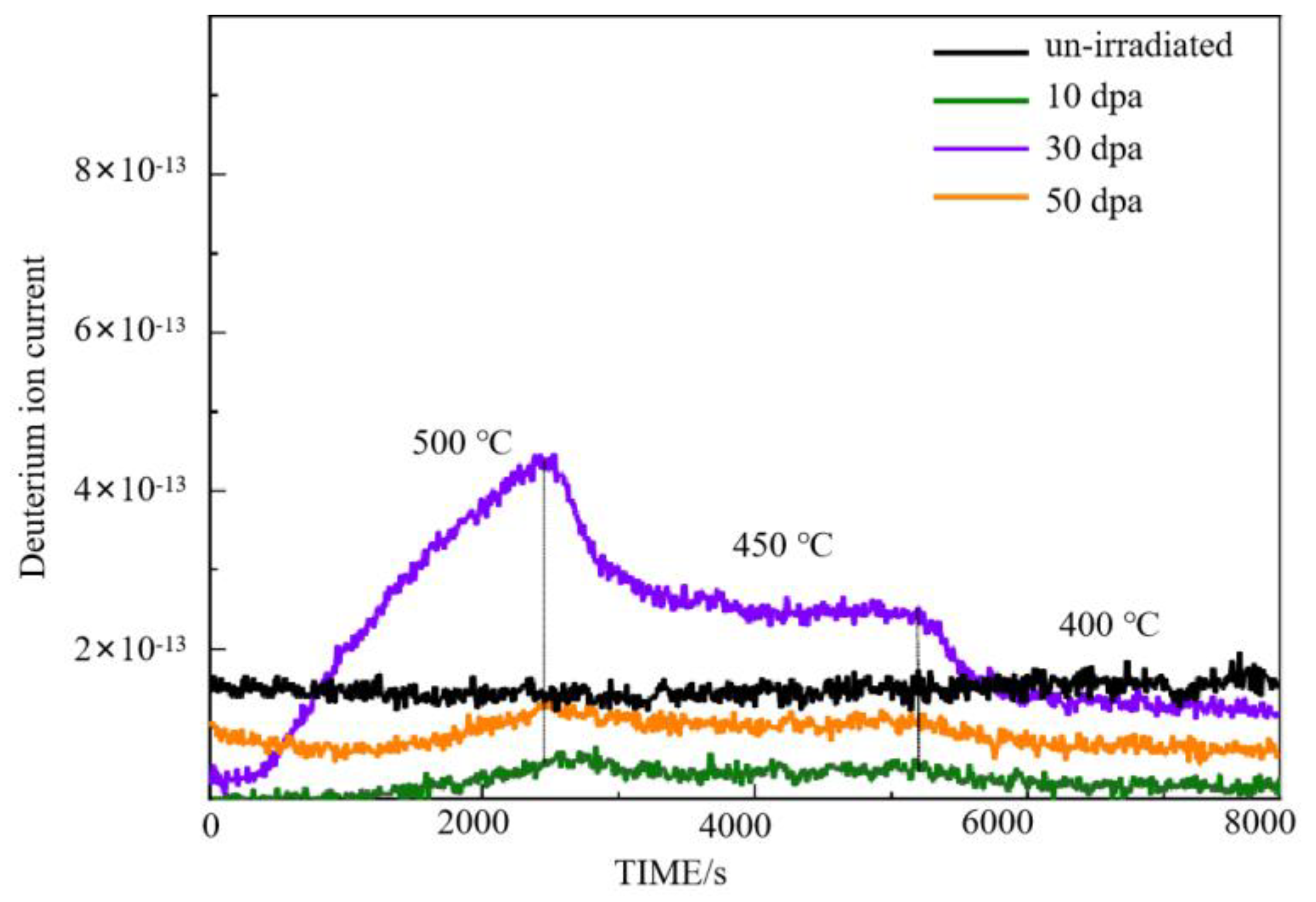
Figure 4.
Cross-section SEM image of Cr2O3/Al2O3 composite coating.
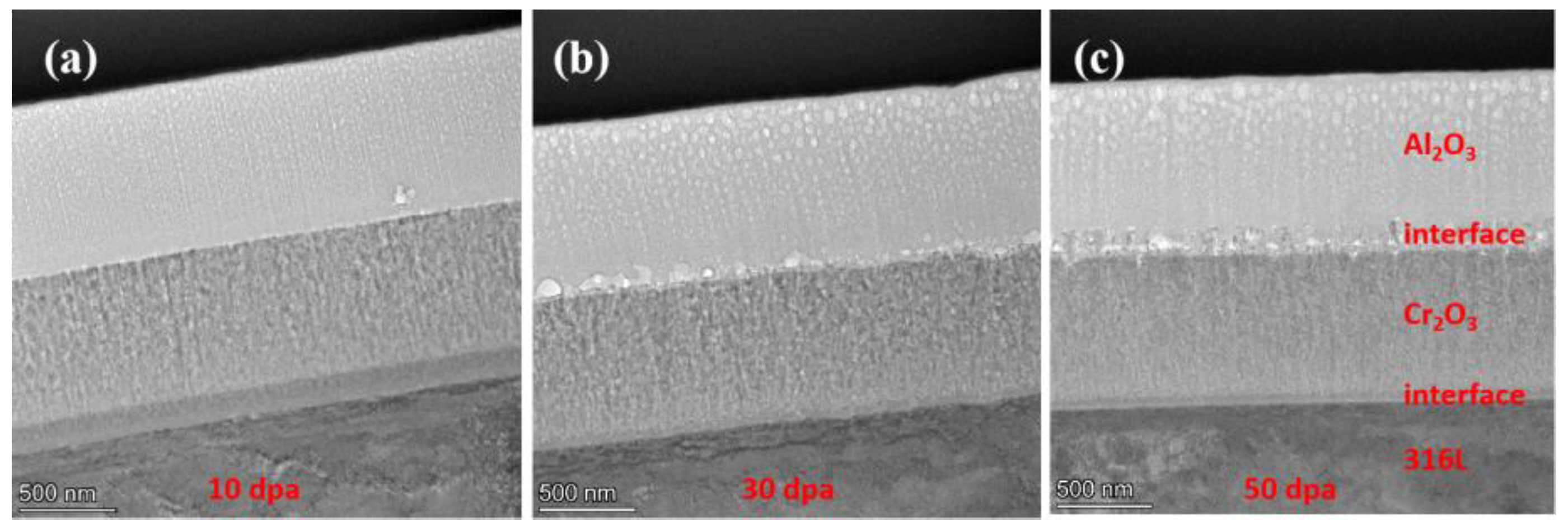
Figure 5.
Surface SEM image of Cr2O3/Al2O3 composite coating.
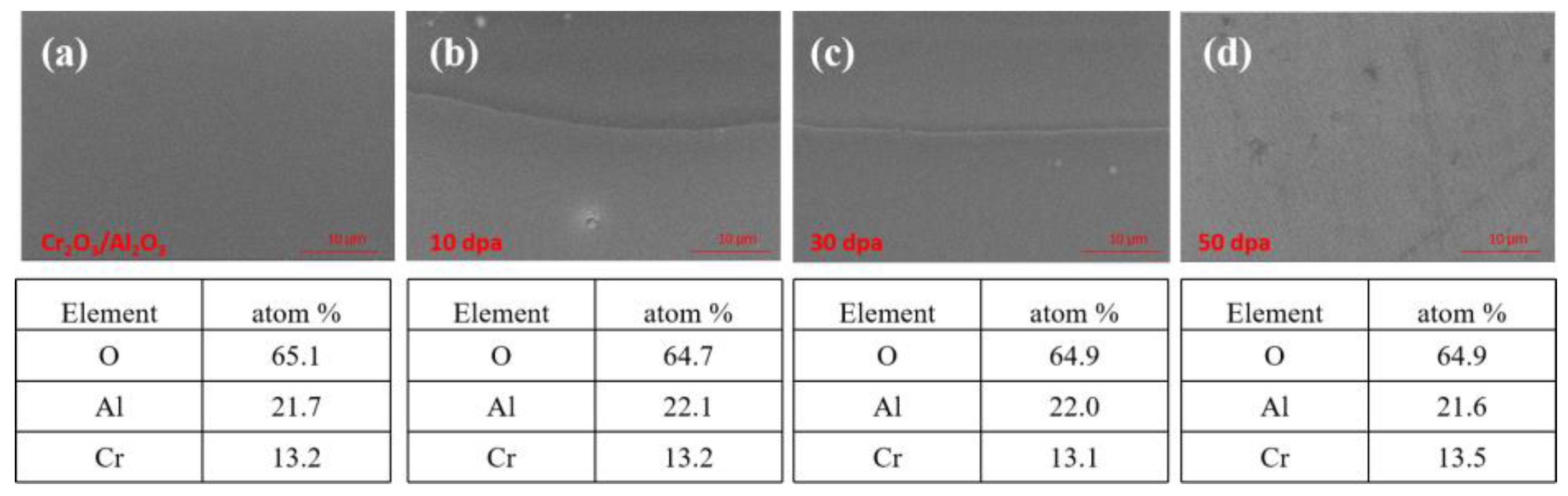
Figure 6.
Cross-section EDS image of Cr2O3/Al2O3 composite coating.
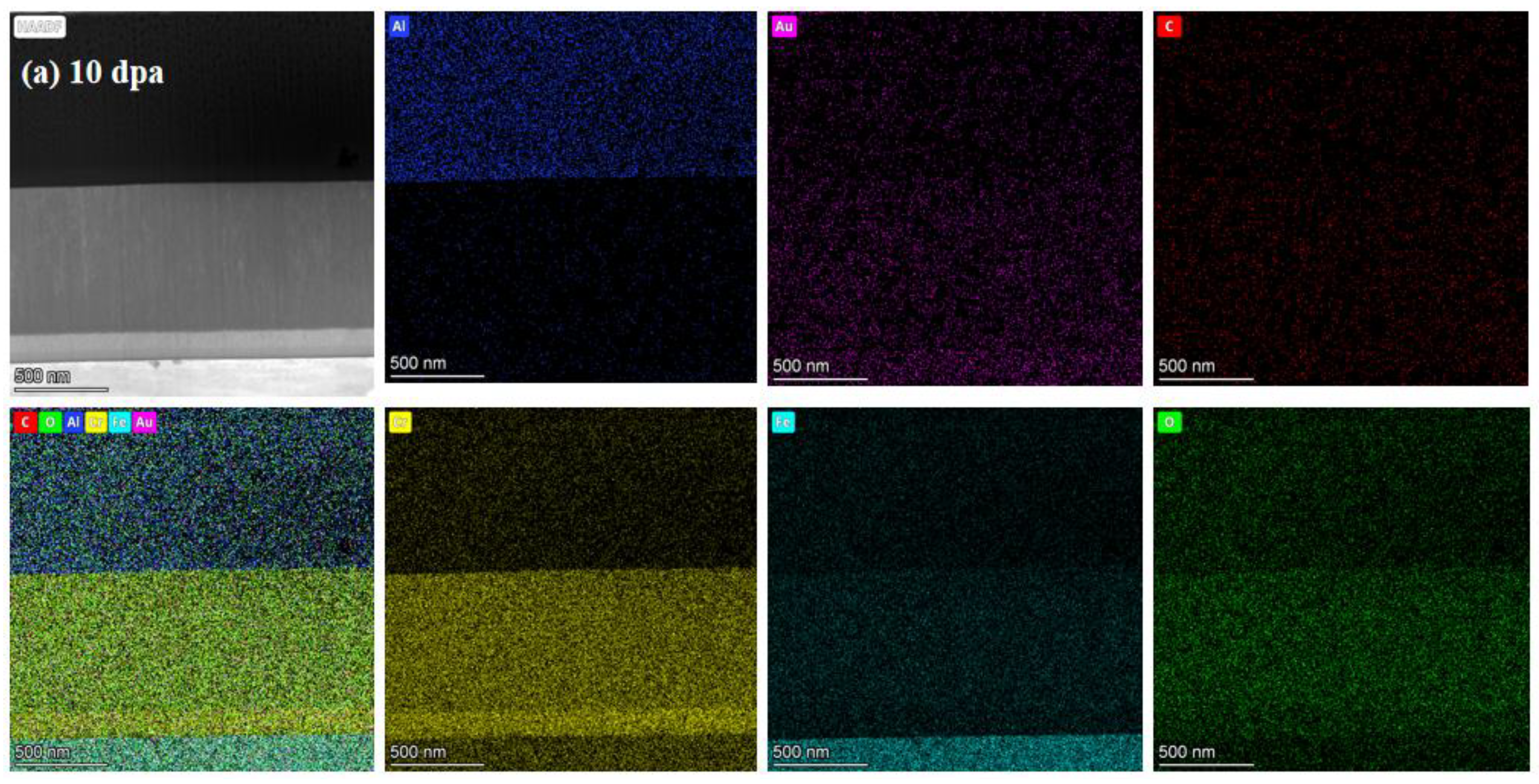
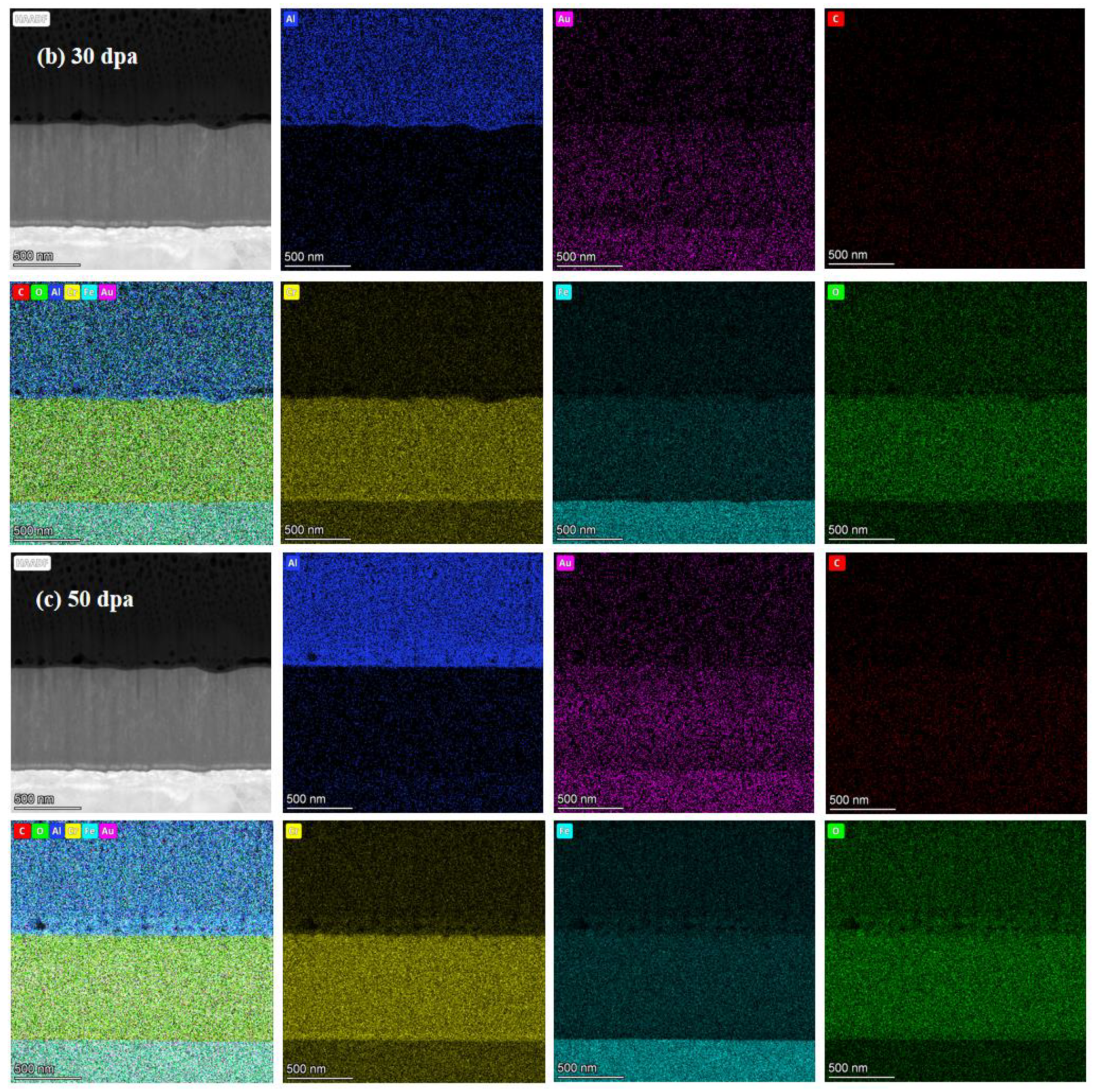
Figure 7.
TEM cross-section image of irradiated coating and corresponding selected-area EDP: (a) 10dpa, (b) 30dpa and (c) 50dpa.
Figure 7.
TEM cross-section image of irradiated coating and corresponding selected-area EDP: (a) 10dpa, (b) 30dpa and (c) 50dpa.
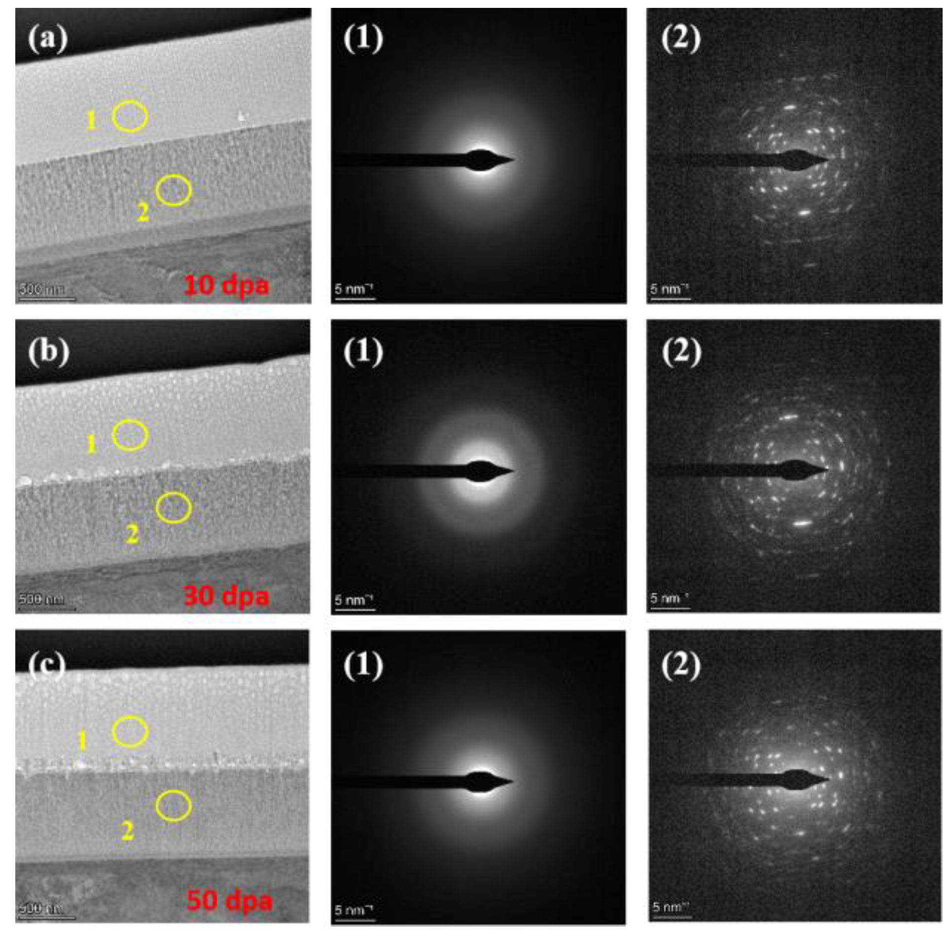
Figure 8.
Deuterium permeation curve of irradiated pre-oxidation zirconium alloy.
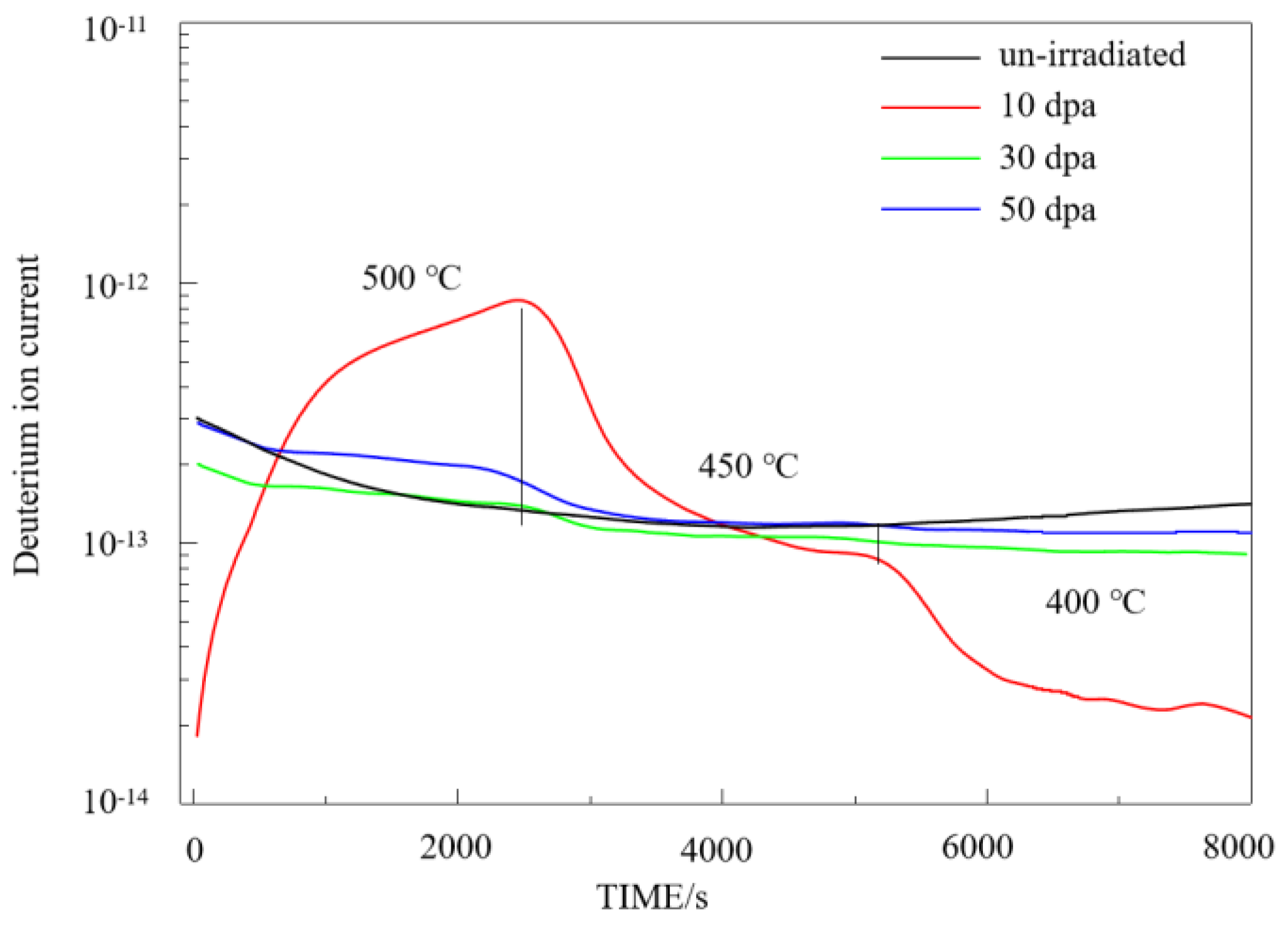
Figure 9.
Cross-section SEM of pre-oxidation layer: (a) 10dpa, (b) 30dpa and (c) 50dpa.
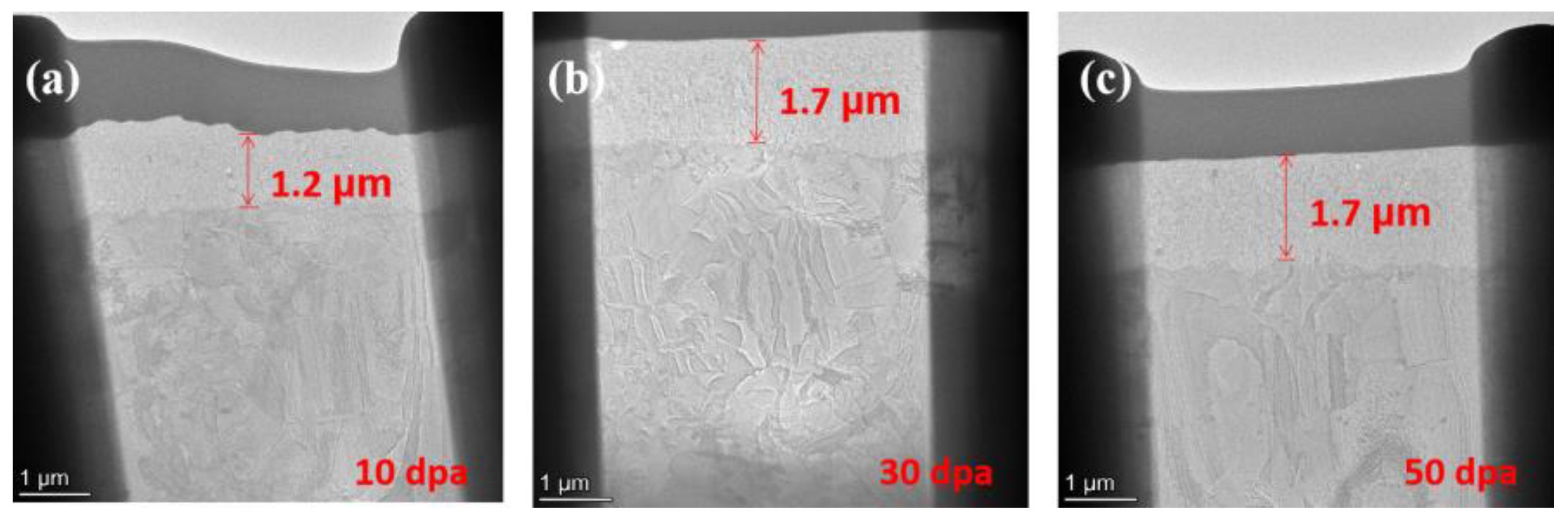
Figure 10.
Surface SEM of pre-oxidation layer: (a) 0dpa, (b) 10dpa and (c) 30dpa (d) 50dpa.
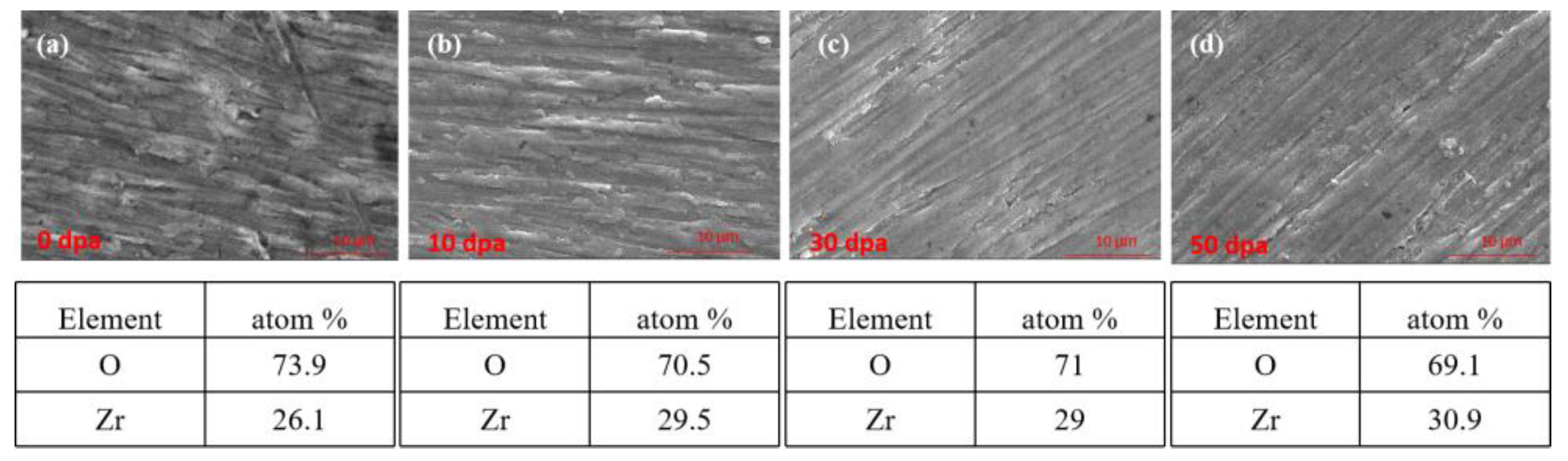
Figure 11.
Cross-section EDS of pre-oxidation layer: (a) 10dpa, (b) 30dpa and (c) 50dpa.
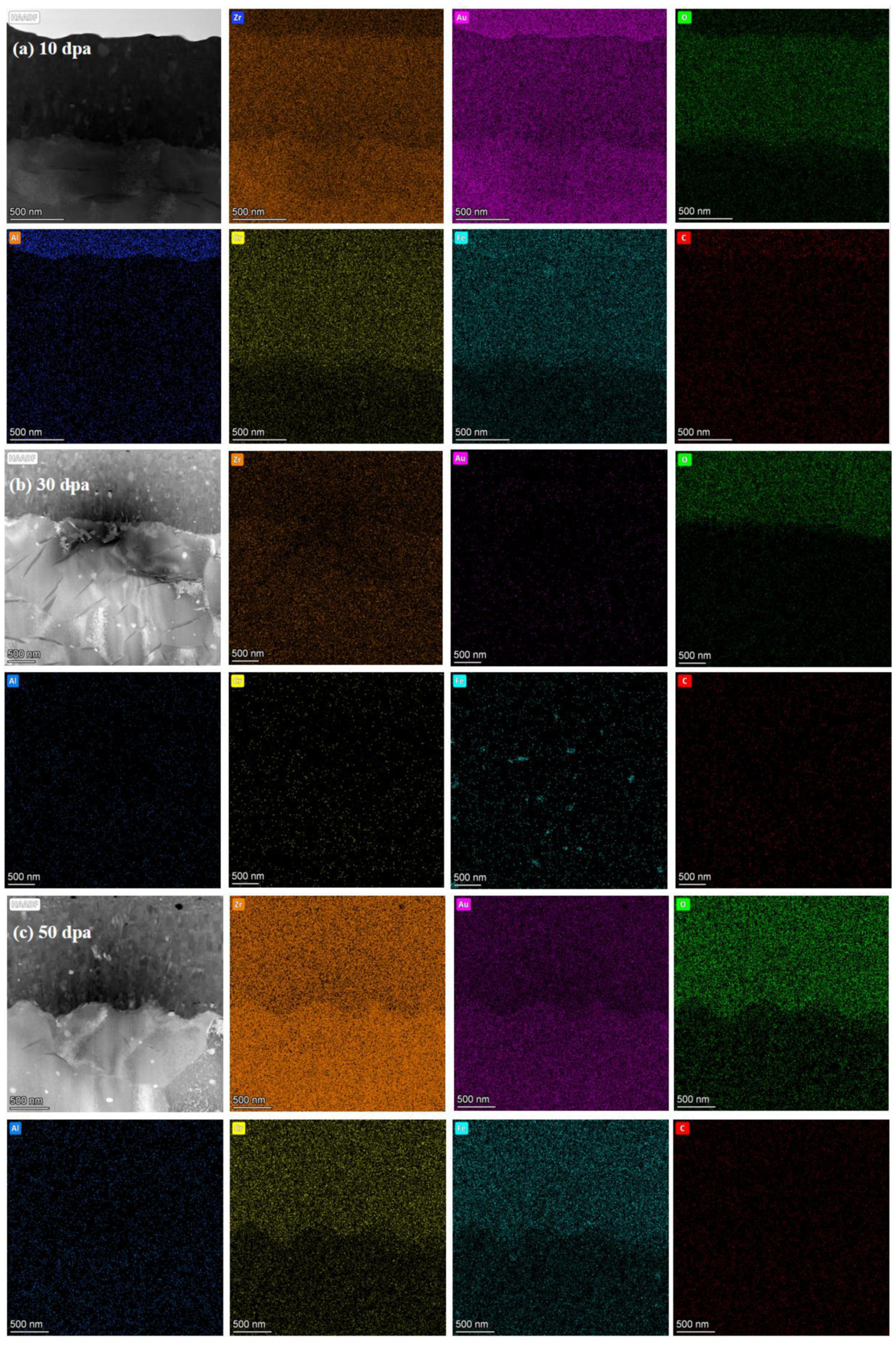
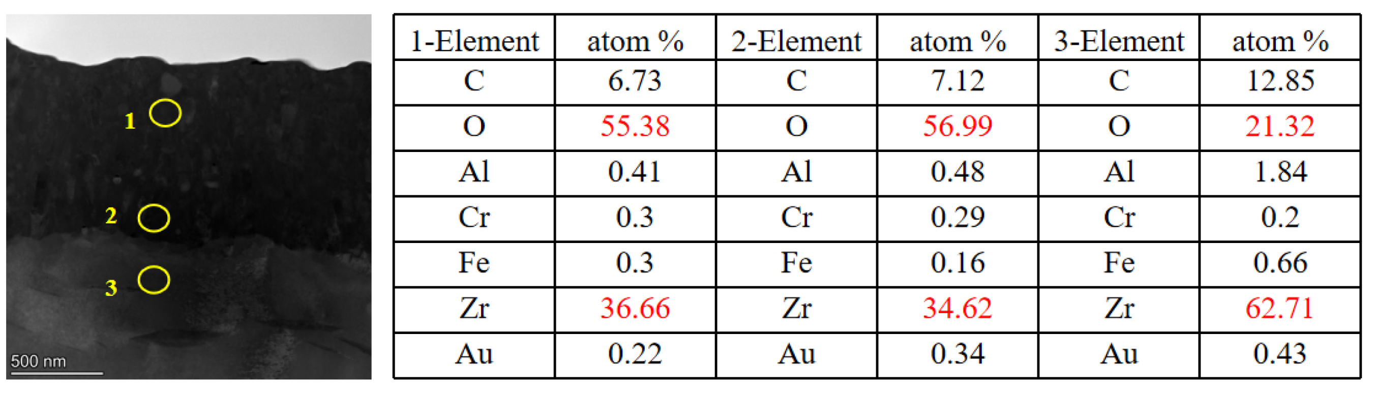
Figure 12.
TEM cross-section image of irradiated pre-oxidation layer and corresponding selected-area EDP: (a) 10dpa, (b) 30dpa and (c) 50dpa.
Figure 12.
TEM cross-section image of irradiated pre-oxidation layer and corresponding selected-area EDP: (a) 10dpa, (b) 30dpa and (c) 50dpa.
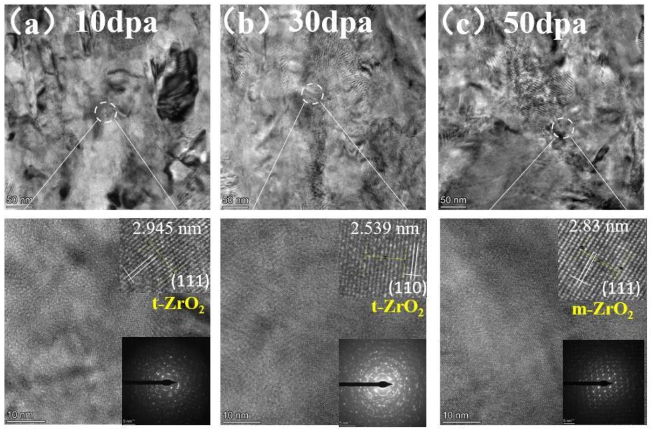

Table 1.
Ion irradiation experimental parameter for coating samples.
| Ion type | Irradiation temperature | Radiation damage dose | Particle beam flow parameters |
|---|---|---|---|
| Au | 450 °C | 10dpa, 30dpa, 50dpa |
|
Table 2.
Deuterium permeation testing condition.
| Temperature | Pressure | |
|---|---|---|
| 500 °C | 100kPa | 500kPa |
| 450 °C | 100kPa | 500kPa |
Disclaimer/Publisher’s Note: The statements, opinions and data contained in all publications are solely those of the individual author(s) and contributor(s) and not of MDPI and/or the editor(s). MDPI and/or the editor(s) disclaim responsibility for any injury to people or property resulting from any ideas, methods, instructions or products referred to in the content. |
© 2024 by the authors. Licensee MDPI, Basel, Switzerland. This article is an open access article distributed under the terms and conditions of the Creative Commons Attribution (CC BY) license (https://creativecommons.org/licenses/by/4.0/).
Copyright: This open access article is published under a Creative Commons CC BY 4.0 license, which permit the free download, distribution, and reuse, provided that the author and preprint are cited in any reuse.


