

Submitted:
14 October 2024
Posted:
14 October 2024
You are already at the latest version
Abstract
This paper studies on aeroelastic control for the two-dimensional airfoil-flap system with unknown gust disturbances and model uncertainties. Open loop limit cycle oscillation (LCO) happens at the post-flutter speed. Structural stiffness of the aeroelastic system is represented by nonlinear polynomials. To robustly suppress aeroelastic vibration within finite time, a backstepping terminal sliding mode control (BTSMC) is proposed. In addition a learning rate is incorporating into the backstepping TSMC to adjusthow fast the aeroelastic response converges to zero. In order to overcome the limitation of the BTSMC design that it is dependent on prior knowledge, a nonlinear disturbance-observer (DO) is designed to estimate the variable observable disturbances. The closed-loop aeroelastic control system is proved to be globally asymptotically stable and converge within finite time by using Lyapunov theory. Simulation results of an aeroelastic two-dimensional airfoil with both trailing-edge (TE) and leading-edge (LE) control surfaces show that the proposed DO-BTSMC is effective for flutter suppression, even when subjected to gusts and parameter uncertainties.
Keywords:
Aeroelastic two-dimensional airfoil
; flutter suppression
; backstepping control
; fast nonsingular terminal sliding-mode control
; nonlinear disturbance observer
1. Introduction
Nonlinear aeroelastic phenomena, such as limit cycle oscillation [1] and free-play flutter [2], not only threaten the aircraft structure, but can even result in loss of control. This challenge attracts many researchers to develop aeroelastic control for flutter suppression and avoidance of LCO [3].Usually passive flutter control has been widely used for wing flutter suppression in practical engineering, such as mass balance, local stiffness enhancement, etc., however, this method requires extra mass and makes the airplane heavier [4]. Therefore, active flutter control has been proposed and the objectives are to suppress flutter and to make the airplane flight exceed its flutter speed.
Active flutter control is a hot topic to suppress wing flutter by using modern control theories. Many researchers proposed useful schemes for active flutter suppression. Ouyang et al. studied the influence of flap camber on the wing flutter bounds, and proposed a Linear Quadratic Guassian (LQG) based control to actively suppress the aeroelastic response by the flap deflection, and the flutter speed and frequency of the wing will be changed by the orders of the reduced order model of the morphing flap camber [5]. Na et. al. proposed a LQG control method with sliding mode control (SMC) observer to active control of composite thin-walled beam structures in compressible flow, the dynamic aeroelastic responses of the beam structures subject to sharp-edged gust, blast loads and sonic-boom are investigated by this method [6]. Compared with linear aeroelasticity, nonlinear aeroelastic issue is more attractive, which includes freeplay, time delay and cubic nonlinearities in aeroelastic systems. Neil et al. studied structure nonlinear effect, analyzed and experimented by a rigid wing supported by a nonlinear spring [7]. Lee et al. presented the effect of a cubic structure restoring force on the flutter of a two dimensional airfoil placed in an incompressible flow, and the results showed the dependence of the divergence flutter boundary on initial conditions for a soft spring, while the independence of the divergence flutter boundary on initial conditions for the hard spring [8]. To stabilize a nonlinear aeroelastic system, Singh et al. proposed an adaptive backstepping output feedback control scheme, and trajectory control of the pitch angle is achieved by this method [9]. To deal with model uncertainties of aeroelastic systems, Lin et al. suggested a decoupled fuzzy sliding mode control (DFSMC), and the DFSMC system was designed to control the plunge and pitch motions simultaneously [10].Chen et. al. proposed a terminal SMC (TSMC)for aeroelastic systems, the LCO suffered in the aeroelastic system is removed by the TSMC [11]. Mukhopadhyay introduced historical perspective on analysis and control of aeroelasticity over the century, and showed some experiments of aeroelastic control for different aircrafts [12]. Bouma et al. investigated structural and aerodynamic nonlinearities effects for three degrees of freedom (DOF) aeroelastic systems, and stall effects were introduced using quasi-steady and unsteady aerodynamic representations [13]. Vishal et al. studied the synchronization characteristics of a pitch–plunge aeroelastic system, possessing discontinuous nonlinearities in both structural and aerodynamic fronts. Meanwhile, a multi-physics fluid–structure interaction problem possessing coupled non-smooth nonlinearities can be alleviated by the use of synchronization theory [14]. Livne gave a survey on aircraft active flutter suppression (AFS) through state of the art, and AFS wind tunnel test and flight-test programs were illustrated [15].
Flutter suppression theory has also been developed by the researchers. Considering delayed control problem, a single time delay was determined according to both the critical stability condition and the stability margins, Zou et al. proposed a delayed proportional–differential (PD) controller for robust suppression the body-freedom flutter (BFF) of a flying-wing drone [16].Trapani and Guo proposed a rudderless aeroelastic fin for a flexible blended-wing-body UAV to improve divergence and flutter margin [17]. Although these methods are useful for the linear time-invariant systems, they cannot guarantee the closed-loop performances of the nonlinear and time-varying aeroelastic system. For the structural nonlinearities and unsteady flow, Zhang and Behal proposed a continuous robust controller to realize aeroelastic vibration control of a two dimensional airfoil [18]. Lee and Singh proposed an L1 adaptive control for the aeroelastic system with unsteady aerodynamics and gust load [19].For the nonlinear aeroelastic system, Platanitis and Strganac proposed a feedback linearization combined with model reference, and it can adaptively suppress LCO of a typical wing section with LE and TE control surfaces [20]. Prime set up a linear parameter varying (LPV) model for the three DOF Nonlinear Aeroelastic Test Apparatus (NATA), and developed a H2 robust control by linear matrix inequalities [21]. Li et al. proposed a state-dependent Riccati equation based method to control an airfoil section with control surface nonlinearities, but it depended on the accurate model [22]. To reduce dependence on the model, Tang et al. proposed a neural network based active flutter suppression under control input constraints [23], but neural networks need extensive calculations. Recently Gao introduced sliding mode control into an aeroelastic system and presented a finite-time fault-tolerant control for wing flutter suppression [24].Chen et al. proposed a free-model deep reinforcement learning algorithm for the active flutter suppression through aeroelsatic wind tunnel testing, thus the jet flow intensity can be intelligently selected according to the real-time state of the flexible wing [25].
Since the aircrafts fly in a varying environment, the influence of model uncertainties and external disturbances on aeroelastic systems have also been considered by the researchers. Pettit briefly described aerodynamic and structure uncertainties and applications of uncertainty with design optimization [26]. For the nonlinear perturbations, Hao et al. analyzed stochastic nonlinear flutter behaviors of 3-DOF wing model by the stochastic p-bifurcation analysis method [27].Lee and Singh proposed a robust higher-order super-twisting control to deal with aeroelastic system with unsteady aerodynamics [28]. To estimate unknown parameters, Prabhu and Srinivas proposed an intelligent observer and then robust control of a three degrees of freedom aeroelastic model [29], but the neural network based observer has a heavy computational load. To improve the convergence speed of the aeroelastic system, Chen et al. proposed a terminal sliding mode control to reach the target within a finite time frame [30], and Yuan et al. proposed a sliding mode observer control for a two dimensional aeroelastic system with gusts [31]. Xu et al. also applied Backstepping Sliding Mode Control (BSMC) design to suppress the LCO with uncertainties and external disturbances [32]. All these methods can suppress or attenuate external disturbances and achieve the desired robust performances, however an alternative approach is available, the so-called disturbance observer based control (DOBC). The DOBC lumps all internal uncertainties and external disturbances acting on the aeroelastic system into a single term and then identifies them by the DO. The DO can provide fast, excellent control performances and smooth control actions without using large feedback gains [33]. Liu and Whidborne have proposed a nonlinear disturbance observer to deal with bounded unknown disturbances [34], but this observer does not cope well with variable disturbances, and the output tracking responses by this DO-BSMC cannot be guaranteed to converge within finite time.
Motivated by Xu’s [32] and Chen’s work [33], this paper considers trajectory tracking control for the two-dimensional airfoil-flap aeroelastic system. The major contributions of this work are as follows:
Considering quasi-steady and unsteady aerodynamic loads, nonlinear dynamic models are set up for an aeroelastic two-dimensional airfoil with both trailing-edge and leading-edge control surfaces.
To suppress flutter, a backstepping terminal sliding-mode control is proposed for the two-dimensional airfoil-flap aeroelastic system. The benefits of this approach have TSMC merits of high robustness, fast transient response and finite time convergence, as well as backstepping control in terms of globally asymptotic stability.
To overcome the limitation of the BTSMC being dependent on prior knowledge, a nonlinear disturbance observer is designed for coping with model uncertainties and variable external bounded gust disturbances, which is different from Backstepping SMC for flutter suppression [32].
To adjust the speed where the aeroelastic response converges to zero, a learning rate is incorporated into the BTSMC design.
Simulation results show the proposed DO-BTSMC method is effective and has advantages in LCO suppression and flutter control for a two-dimensional wing with LE and TE control surfaces.
This paper is organized as follows. Section 2 establishes the nonlinear aeroelastic dynamics model of the two-dimensional airfoil-flap system. Section 3 proposes a DO-BTSMC design, and stability is analyzed for the closed-loop control system. Simulations and analysis are in Section 4. Some conclusions are given in Section 5.
2. Aeroelastic System Dynamic Model
The studied model is a two-DOF pitch-plunge wing section with both LE and TE control surfaces and is shown in Figure 1, both control surfaces are used as control inputs.
The physical parameters of the wing are listed as follows, a is nondimensional distance from midchord to elastic axis position, b and c denote semichord and full chord length of wing section respectively.
Cmα, eff , Cmβ, eff , and Cmγ, eff are the effective dynamic and control moment derivatives due to angle of attack and trailing- and leading-edge control surface deflection, respectively, about the elastic axis and are defined as follows
mT denote total mass of pitch–plunge system, cα and ch denote damping of pitch and plunge respectively, kα and kh denote pitch and plunge stiffness respectively, sp is wing section span, Iα denotes total pitch moment of inertia about elastic axis,ρ denotes air density, h is plunge displacement, V is freestream velocity, α is angle of attack (AOA),β and γ trailing- and leading-edge control surface deflection respectively, CL, CLα, CLβ, CLγ denote wing section lift coefficients and Cm, Cmα, Cmβ, Cmγ denote wing section pitch moment coefficients at quarter-chord.
Denote the state variable vector is
and uncertain functions of plunge and AOA motions are
The servo motor dynamics for the TE and LE can be modeled as a second-order system of the form
whereandare the damping of the TE and LE respectively, and are stiffness of the TE and LE respectively, andanddenote the desired positions of the servo motors for the TE and LE respectively.and denote the rotational wingbody of mass and inertia respectively, , and are the moments of inertia of the TE and LE about its pivot respectively , ,, and are the rotational TE and LE section of mass and inertia respectively. Let,denotes a translational body of mass.
When the aerodynamic performance of the airfoil is unsteady, the equations of motion for the entire system can be set up by Lagrangian energy theory,
where denotes Lagrangian function. The expanded form of (10) is
wherea * denotes symmetric matrix element,
The aerodynamic force and moment in (8) can be calculated by Theodorsen method [35,36]
where Ti (i =1,2,…,14) are the Theodorsen constants, see Appendix B [37]. is derived from those by Throdorsen [35,36,37].
The aerodynamic force and moments in (13)-(15) are dependent on Theodorsen function C(k), where k is the non-dimensional reduced frequency of harmonic oscillation, C(k) can be approximated by Jones method,
where c1=0.0075, c2=0.10055, c3=0.0455, c4=0.3. C(s) can be presented as a state-space model as follows
where
The aerodynamic force and moments can be described as the sum of non-circulatory and circulatory loads,
where Fnc and Fc are non-circulatory load and circulatory load respectively. Denote, xa = [xa1, xa2]T, then we get
where xα is nondimensional distance from elastic axis to centre of mass, and meeting xα= rcg /b, rcg is distance from elastic axis to centre of mass.
andare the Theodorsen constants for the TE and LE respectively. Substitute (17) , (13) - (15) into (11), then yields
where(3)
Denote the full state vector, the overall state-space model is
where the A and B matrix are as follows
where
Since there exists wind disturbance for the aeroelastic system, then the external disturbance D is considered and added into the system of (6) and (25) as
whereand denote external disturbances and bound by, DU is a real value meeting DU≥0. Denote ,
. The aerodynamic loads due to the wind disturbances are defined as [38]
wheredenotes the disturbance velocity, τ is a dimensionless time variable defined as , so .Suppose that the above disturbance can be generated by a linear exogenous system [33],
where,Wd, Vd are coefficient matrices with corresponding dimensions.
Airfoil aeroelastic vibration Control Problem: The control objective is to suppress the aeroelastic vibrations, so the desired smooth trajectory xd can be chosen to be zero for all time. Alternatively the desired trajectory xd along with the actual pitching and plunging variables is driven toward the origin.
3. DO-BTSMC Aeroelastic Control Design
This section gives an overview of the DO-BTSMC control for the two dimensional airfoil.
3.1. Nonlinear Disturbance Observer Design
Considering unknown disturbances in the aeroelastic system (28), a nonlinear disturbance observer (NDO) is proposed to improve the tracking precision [33],
whereis the estimated disturbance, l (x) is the vector of observer gains to be tuned for performance, zd is the internal state vector, and pd(x) is a nonlinear function to be designed. The NDO gain l(x) is determined by
Integrating l(x2) with respect to the aeroelastic system state x yields,
where Ld is a gain vector, Lief denotes a Lie derivative of function f(x), and r is the relative degree. Select. The nonlinear disturbance estimation error is.
It has been shown that the estimationof the NDO approaches the disturbance D(t) exponentially if the observer gain l(x) is chosen such that (32) is global exponentially stable for all [39]. The estimation of harmonic disturbance, , yielded by the DO of (32) approaches the disturbance, D, and is global exponentially stable if the following inequalities are satisfied [33]
Hence the disturbance compensator can be designed as
By using the nonlinear disturbance observer, will approach D, so the disturbance can be attenuated through the disturbance compensator (36) and the system (28) can be transformed as follows
The observable disturbances usually can be measured and estimated by the observer, such as 1-cosine winds. It has been shown that the estimation of the NDO approaches the disturbance D(t) exponentially if the error dynamics for d(t) is global exponentially stable [33]. By the similar method, the disturbances for unsteady loads can also be estimated.
3.2. DO-BTSMC Based Aeroelastic Control Design
To drive the aeroelastic output x to converge to the desired value vector xd, the aeroelastic controller is designed as follows.
The tracking error vector of the plunge displacement and pitch angle is defined as
and its derivative is
Define the stabilizing function, as the virtual speed vector of
whererepresents the reference or virtual speed vector, K1>0 is often chosen as a diagonal matrix to simplify the design, i.e., K1 =diag(k11, k12), k1i (i = 1, 2) is constant value.
Construct Lyapunov function V1 as follows
Define the speedtracking error vector for the plunge and pitch dynamics as
and its derivative is
The detailed derivation is given in the Appendix A.
Remark 1 If there are uncertainties for the system (28), then f2 and g2 will include uncertain terms, the uncertain terms can be regarded as disturbances and added into D, and then the observer (32) can be used with nominal f2 and g2.
Therefore, the structure of the DO-BTSMC controller for aeroelastic control is designed as Figure 2, which includes aeroelastic dynamics system of the two dimensions airfoil, an adaptive BTSMC used for aeroelastic flutter suppression, a nonlinear DO used to estimate observable disturbances, and an adaptive disturbance estimator used to observe the unobservable disturbances. A learning rate is applied to speed up the convergence of the proposed sliding mode control.
4. Discussion
The studied aeroelastic system is the NATA model and the physical parameters of the aeroelastic system are listed in Table 1 [20,21,40].
4.1. Flutter Suppression
In this section, flutter suppression of the airfoil is studied. For the two dimensional airfoil, the polynomial model of the stiffness is found by static measurements on the nonlinear pitch cam, kα(α) =12.77+53.47α+1003α2Nm/rad [20]. When the airspeed is increased up to 11.4m/s, the LCO phenomenon appears. The output responses are shown in Figure 3. To suppress this LCO and flutter vibrations, different scenarios are studied as follows. First the proposed BTSMC is used to suppress this flutter. The initial conditions of the two-dimensional aeroelastic airfoil are h(0)= −0.01m, α(0)=0.1rad,(m/s), (rad/s), the nominal airspeed V =11.4m/s. The parameters of the BTSMC are designed after several design iterations as follows,K1=diag(0.2,0.1), hs=diag(0.5,0.5), ς=diag(30,45),φs=0.4,βs=1,p=5, q=3, β=diag(1,1), α0=10, β1=3, λ=1.8*diag(1,1). By using the proposed BTSMC design, the simulation results refer to Figure 4.
It can be seen from Figure 4 that the dynamic responses of the proposed nonlinear aeroelastic system flutter under the initial input in the first 2 sec, and the resulting dynamic responses under the BTSMC are stable after 2sec. The FFT results of plunge displacements and AOA with and without BTSMC control are shown in Figure 3 and Figure 4, the vibration frequency is 2.7Hz (see Figure 3), and the amplitude of hFFT changes from 1.5×10⁻³ to 1.25×10⁻⁴, while the amplitude of αFFT changes from 0.1 to 7.4×10⁻³, which shows the flutter is suppressed by the proposed BTSMC.
For high stiffness nonlinearity in pitch, kα(α) can be presented as the following polynomial type [21],

The flutter speed is related to its stiffness, the flutter equation for the p-k method can be written as follows by Eq. (23) [41],
where M and K are the generalized mass and stiffness matrices, respectively; QR and QI are the real and imaginary parts of the generalized aerodynamic force matrix that depends on Mach number M and reduced frequency k. V is the velocity of undisturbed flow, Lref is the reference length. q denotes eigenvector of flutter equation, p = gs+iωs is non-dimensional Laplace complex parameter and is also refered to as an eigenvalue of Eq.(44). The imaginary part of p must meet the following consistency condition, , i.e.,, and . When the damping curve {(Vs,gs)} for the vibration mode intersects with gs =0, the associated speed is flutter speed. Therefore, for a given k, when the stiffness K is increased, the frequence is increased, and the flutter speed Vs is increased. Here the high stiffness is applied, the flutter speed is increased from V = 11.4m/s to V=13.2m/s. By using this stiffness the simulation results refer to Figure 5 and Figure 6,
It can be seen from Figure 5 and Figure 6 that the flutter speed is increased from V=11.4 m/s to V=13.2m/s by the high stiffness nonlinearity, and the output responses of plunge and pitch motions are quickly convergent by the proposed BTSMC control.
Considering high angle of attack (AOA) in the post-flutter behavior, a command of 10deg square wave is tracked and the output responses are shown as Figure 7,
It can be seen from Figure 7 that 10deg AOA command has been accurately tracked by the proposed BTSMC, but it is easy to make the control surfaces saturation and results in small oscillations of the output responses.
4.2. Flutter Suppression under Unknown Wind Disturbances
Case I: for quasi-steady aerodynamic loads
There are two kinds of gusts to be studied here, that is, a triangular-type gust and a sine gust as follows [32,38]
where H(⸱) denotes the Heaviside step function to describe the typical velocity distribution time-history corresponding to the gust loads, this triangular gust lasts 0.5s from t =0 to t = 0.5s, i.e. tG = 0.05s, w0 =0.3m/s, .
where w0 =0.3m/s, and this sine gust lasts 120 s from t =0 to t = 120s.
Note that the triangular gust is very similar to the traditional 1-cosine gust-type function, both of which can be classified as ephemeral disturbances. Since gusts will result in the lift force and pitch moment change, which then drive the vertical speed and pitch rate change, for simplification, we regard them as the external disturbances by
whereis the effectiveness matrix of gust, which can be approximate by Eqs.(29) and (30),
The disturbance parameters of (31) are
The associated DO gains of (33) are designed as follows
Remark 2 In this paper single (1-cos) gusts (i.e. triangular gust) and continuous sinusoidal (harmonic) gusts are considered. It can be seen from Eqs (49) and (50) that the observer gains of l (h,
) are different for different kinds of gusts, which shows the DO is adaptive for the gusts. Different kinds of gusts can be detected by the short-range light detection and ranging (Lidar) wind measurement.
The parameter of the adaptive observer (A19) is set as γd = 0.2. To illustrate our method in trajectory tracking control, a BSMC design from [42] is used for comparison. The sliding mode surface is designed as
and the BSMC controller is designed as follows
And a PID controller is applied as follows
The parameters of the studied controllers are designed as Table 2 after several design iterations.
By using the proposed DO-BTSMC, BSMC and PID design, the simulation results refer Figure 8, Figure 9, Figure 10, Figure 11, Figure 12, Figure 13 and Figure 14 and Table 3 and Table 4.
Example 1 Firstly, we consider different cases of the BTSMC design with and without learning rate αr under triangular gust of (44), and the DO is applied, the output responses are shown in Figure 8 and Figure 9 and Table 3, where the reference inputs of root mean square error (RMSE) are hcmd =0, αcmd=0.
Example 2 Secondly, we consider the case of the BTSMC design with and without DO under sine gust of (45), and there is no learning rate, the output responses are shown in Figure 10 and Figure 11 and Table 3.
Considering triangular gust input, it can be seen from Figure 8 and Figure 9 and Table 3 that the resulting dynamic responses of the proposed nonlinear aeroelastic system are stable, and the rise-time of plunge responses for BTSMC with learning rate and DO is shorter than that of the BTSMC without learning rate but with DO, which shows the tracking speed of the BTSMC with learning rate for the plunge motions is faster than that of the BTSMC without learning rate, but LR can produce a small overshoots, see Figure 8. The root mean square errors of the plunge and pitch motion for the BTSMC with LR and DO are smaller those for the BTSMC without LR. This shows the learning rate of the BTSMC can improve the control performance.
Now considering sine gust input, Figure 10, Figure 11 and Table3 show that the resulting dynamic responses of the proposed nonlinear aeroelastic system are stable, and the steady-state errors of the BTSMC with DO for the plunge and pitch motions are less than those of the BTSMC without DO. The associated control inputs for the LE control surface are smaller than that of the BTSMC without DO. This shows the disturbance observer of (32) and (A19) can effectively estimate the unknown time-varying gust and the disturbance compensator reduces the disturbance effect for the aeroelastic system.
Finally, we consider the different flutter suppression approaches of the BTSMC, BSMC and PID under triangular gust of (44).By using the proposed design with the DO of (32) and adaptive observer (A19), the output responses are shown in Table 4 and Figure 12, Figure 13 and Figure 14. The sign function of the SMC design is replaced by the tangent hyperbolic function with a boundary layer (where φs =0.4),
It can be seen from Figure 12. and Table 4 that the resulting dynamic responses of the proposed nonlinear aeroelastic system are convergent to the desired values, and the rise-time of plunge responses for DO-BTSMC is shorter than those of the DO-BSMC and DO-PID control, which shows the BTSMC response is the fastest among them. The output responses of the PID control easily oscillate under triangular gust while the responses of the BTSMC and BSMC design are steady after transition process, which shows the robust performances of the BTSMC and BSMC. The root mean square errors of the plunge and pitch motion for the DO-BTSMC are the smallest, while those for the PID control are the highest, and RMSEs for the DO-BSMC are in the middle of them, which show tracking precision of the DO-BTSMC is the highest, the second one is the DO-BSMC, the last one is the PID control. Figure 10 shows that the triangular gust of (44) can be effectively estimated and the unobservable disturbances including model uncertainties are estimated by the adaptive observer (A19), see Figure 14, which reduce effect of the triangular gust on the aeroelastic system.
Case II: for Unsteady aerodynamic load
As the post-flutter behavior of the airfoil is intrinsically unsteady, so the unsteady aerodynamic loads are calculated by (10)-(27), and the parameters of the studied controllers are designed as Table 5 after several design iterations.
The associated DO gains of (33) are designed as follows
Example 3 Firstly, we consider different cases for the BTSMC design with and without learning rate αr under triangular gust of (44), and the external disturbances by(46), whereis the gust effectiveness matrix, which can be approximate as
where, the disturbance parameters are the same as Example 1 with w0 =3m/s, and the DO is applied, the output responses are shown in Figure 15, Figure 16 and Figure 17.
The control inputs refer to Figure 18.
The wind disturbances are estimated by the proposed DO (32) and refer to Figure 19.
Example 4 Secondly, we consider the case of the BTSMC design with and without DO under sine gust of (45), the disturbance parameters are the same as Example 2, and there is no learning rate, the output responses are shown in Figure 20, Figure 21, Figure 22 and Figure 23 and Table 6.
The control inputs refer to Figure 23.
Considering triangular gust input, it can be seen from Figure 15, Figure 16 and Figure 17 and Table 6 that the resulting dynamic responses of the proposed nonlinear aeroelastic system are stable, and the rise-time of plunge responses for BTSMC with LR and DO is shorter than that of the BTSMC without LR but with DO, which shows the tracking speed of the BTSMC with learning rate and DO for the plunge motions are faster than that of the BTSMC without learning rate, but LR can produce a small overshoot, see Figure 15, Figure 16 and Figure 17. The RMSE of the plunge and pitch motion for the BTSMC with learning rate and DO are smaller than those for the BTSMC without LR. It shows the learning rate of the BTSMC can improve the control performances.
Now considering sine gust input, Figure 20, Figure 21, Figure 22 and Figure 23 and Table3 show that the resulting dynamic responses of the proposed nonlinear aeroelastic system are stable, and the steady-state errors of the BTSMC with DO for the plunge and pitch motions are less than those of the BTSMC without DO, and the associated control inputs are smaller than those of the BTSMC without DO. It shows the disturbance observer of (32) and (A19) can effectively estimate the unknown time-varying gust and the disturbance compensator reduces the disturbance effect for the aeroelastic system. Figure 19 shows that the external disturbances can be estimated quickly and accurately.
4.3. Robust Flutter Suppression with Parameter Uncertainties and Disturbances
Case I: for quasi-steady aerodynamic loads
Example 5 Considering parameter uncertainties of the aeroelastic system, we set them as follows according to parameters perturbation when the work conditions change, uncertainties of kh, kα, and ch are ±1%, uncertainty of cα and CLα are ±30% and ±7% respectively. Meanwhile the external disturbance is set as a sine gust of (45). The controller parameters are designed and listed in Table 2, and the sign function of the SMC design is replaced by a continuous approximation of sign function with βs =1. Since the DO-BTSMC can deal with model uncertainties through adaptive disturbance estimation and gain regulation, then we use the proposed DO-BTSMC design, and the simulation results are shown in Table 7 and Figure 24, Figure 25, Figure 26 and Figure 27.
It can be seen from Figure 24 and Table 7 that the resulting dynamic responses of the proposed nonlinear aeroelastic system are convergent, and the rise-time of plunge responses for DO-BTSMC is the shortest, which shows the BTSMC response is the fastest among them, and demonstrates the DO-BTSMC has fast transient response and finite time convergence. But BTSMC will produce larger overshoots than those of BSMC and PID design, this is because more inputs are required for finite time convergence in the transition process for the DO-BTSMC. The RMSEs of the plunge and pitch motion show tracking precision of the DO-BTSMC are the best, and then is for the DO-BSMC, the last one is for the PID control. Meanwhile, the output responses of the PID control are vibrating under the sine gust, which shows that the robust performance of the PID controller is less than that of the BTSMC and BSMC. Figure 25 shows that the sine gust of (45) can be effectively estimated and the unobservable disturbances are also estimated by the adaptive observer of (A19) as Figure 26, which reduce the effect of the sine gust on the aeroelastic system. Figure 27 shows that the control surface deflections of DO-BTSMC are the smallest and fastest, but the control inputs of the DO-PID control are the largest and easily drive the control surface saturation, which also demonstrates the BTSMC robust performances.
Case II: for Unsteady aerodynamic load
Example 6 For unsteady aerodynamic loads with disturbances and model parameter uncertainties, the parameters of disturbances and uncertainties are the same as Example 5, we use the proposed DO-BTSMC design. The simulation results are shown in Table 8 and Figure 28, Figure 29, Figure 30, Figure 31, Figure 32 and Figure 33.
It can be seen from Figure 28–30 and Table 8 that the resulting dynamic responses of the proposed nonlinear aeroelastic system are convergent, and the rise-time of plunge responses for DO-BTSMC is the shortest, which shows the BTSMC response is the fastest among them, and illustrates the DO-BTSMC has fast transient response and finite time convergence. But BTSMC will produce larger overshoots than BSMC and PID design. This is because more inputs are required for finite time convergence in the transition process for the DO-BTSMC. The root mean square errors of the plunge and pitch motion for the DO-BTSMC are 0.0010m and 0.0183rad respectively, and those for the DO-BSMC are 0.0010m and 0.0151rad respectively, while those for the PID control are 0.0017m and 0.0199rad respectively, which show tracking precision of the DO-BSMC is the best, then is for the DO-BTSMC, the last one is for the PID control. Although the tracking precision of the DO-BSMC is better than that for the DO-BTSMC, the rise-time of plunge motion response for DO-BSMC is very slow, which shows its vulnerable damping.
The disturbance can be estimated by the proposed DO (32) and (A19), the outputs refer to Figure 31 and Figure 32.
The control inputs refer to Figure 33.
Figure 31 shows that the sine gust of (45) can be effectively estimated and the unobservable disturbances are also estimated by the adaptive observer of (A19) as Figure32, which reduces the effect of the sine gust on the aeroelastic system. Figure 33 shows that the control surface deflections of DO-BTSMC are the smallest and fastest. And the control inputs of the DO-BSMC control are the largest and easily drive the control surface saturation, which also demonstrates the DO-BSMC has small damping and reduce its tracking performances.
5. Conclusion
A nonlinear backstepping nonsingular terminal SMC method is used to design a controller to suppress limit cycle oscillation (LCO) and flutter. The developed controller stabilizes the plunge and pitch motions of the two dimensional airfoil with LE and TE control surfaces within finite-time convergence. Stability analysis shows that the closed-loop aeroelastic dynamics are globally asymptotically stable. Six examples of the variable bounded disturbances of triangular gust and sine gust and model parameter uncertainties are simulated. Compared with the BSMC and PID controllers, the DO-BTSMC with learning rate achieves better flutter suppression performances in fast response (improved by 18.6%) and root mean square error( reducing 75% for α). Therefore, the effectiveness and availability of the DO- BTSMC design are demonstrated.
Funding
This research was funded by the National Natural Science Foundation of China (No. 52272400 and No.10577012), which we gratefully acknowledge.
Appendix A. Aeroelastic Controller Design
Substituting (40) and (42) into (39) yields
that is,
Differentiating (A2) and substituting (38) yields
From (40) and (A1), the derivative of the stabilizing function is
The derivative of the first CLF of (41) can be rewritten as follows by substituting (A1)
Now a non-singular terminal sliding mode (NTSM) surface with learning rate is designed by using the fractional order derivative as follows [43]
where denotes sliding mode surface, 1<p/q <2, i=1,2, sgn(.) is sign function, the SMC parameter λ > p/q.
To adjust the speed where the aeroelastic responses converge to zero, a learning rate is proposed as follows
where α1 is learning rate, which is defined as ,is positive constant, ,.So the derivative of sliding mode surface s of Eq.(A6) is as follows by using Eq.(A3),
The candidate CLF is redefined as
where γd is a positive constant that determines the convergence speed of the estimate. Differentiating (A9) yields
Since d is an unknown constant or slow-varying disturbance, the derivative of the estimated parameter error is
where and are the estimated parameter vector of d and the associated estimated parameter error vector. Substituting (37),(A5), (A8), and (A11) into (A10) yields
A desired control input is selected as follows to make (A12) semi-negative definite,
As
And define the positive definite matrix
Where
then yields
And
where hs, ς are sliding-mode parameters. The sliding mode term in the backstepping design is to improve system adaptiveness to model uncertainties, even in the presence of the disturbances.
Substituting into (A17) yields
Choose the update law as:
if ,, then
Therefore, robust stability of the closed-loop system can be guaranteed by using the DO-BTSMC controller according to Lyapunov theory.
Appendix B. Expression for the T Functions
Unsteady aerodynamic load expressions in two dimensional incompressible flow by Theodorsen
References
- E., H. E., H.Dowell, A Modern Course In Aeroelasticity, Kluwer Academic Publisher, Norwell, MA. 2005. [Google Scholar]
- J., T. J., T., Gordon, E., E., Meyer, and R., L. Journal of Aircraft, 2008. [Google Scholar]
- V. Journal of Guidance, Control, and Dynamics, 2003.
- Y Chai, W Gao, B Ankay, F Li, C Zhang. Aeroelastic analysis and flutter control of wings and panels: A review, International Journal of Mechanical System Dynamics. 2021.
- Y Ouyang, Y Gu, X Kou, Z Yang. Active flutter suppression of wing with morphing flap. Active flutter suppression of wing with morphing flap. Aerospace Science and Technology. 110(2021)10 6457.
- S. Na, J.S. S. Na, J.S. Song, J.H. Choo, Z.M. Journal of Sound and Vibration, 2011. [Google Scholar]
- T. O’Neil, T.W. T. O’Neil, T.W. Journal of Aircraft, 1998. [Google Scholar]
- H.K. Lee, L. Y. H.K. Lee, L. Y. Jiang, Y. S. Journal of Fluids and Structures, 1999. [Google Scholar]
- S.N. Singh, L. S.N. Singh, L. Journal of Guidance, Control, and Dynamics, 2002. [Google Scholar]
- C. M. Lin, W. L. C. M. Lin, W. L. Journal of Guidance, Control, and Dynamics, 2006. [Google Scholar]
- C. L. Chen, C. W. C. L. Chen, C. W. Chang, H. T. Nonlinear Dynamics, 2012. [Google Scholar]
- V. Journal of Guidance, Control, and Dynamics, 2003.
- A. Bouma, R. A. Bouma, R. Basconcellos, A. International Journal of Non-Linear Mechanics, 2023. [Google Scholar]
- S. Vishal, R. S. Vishal, R. Ashwad, B. Chandan, J. 2021. [Google Scholar]
- E. Journal of Aircraft, 2018.
- Q.T.Zou, R. Q.T.Zou, R.Huang, and H.Y. Hu, Body-freedom flutter suppression for a flexible flying-wing drone via time-delayed control,Journal of Guidance, Control, and Dynamics, 45(1)( 2022).
- M.Trapani and S. Guo, Design and analysis of a rudderless aeroelastic fin, Proc. J: IMechE Part G, 2009.
- K.,Zhang, and A. Journal of Vibration and Control, 2016.
- K., W. K., W., Lee, and S., N. L, 2016. [Google Scholar]
- G., Platanitis, and T., W. Journal of Guidance, Control, and Dynamics, 2004.
- Z.D. Prime, Robust Scheduling control of aeroelasticity, PhD dissertation, University of Adelaide, Australia, (2010).
- D.C., Li, S.J. Guo, J.W. Journal of Sound and Vibration, 2010.
- D., Tang,L., Chen, Z., F.,Tian,and E. Journal of Vibration and Control, 2021; (3.
- M.,Z.,Gao, G., P., Cai, and Y. Control Engineering Practice, 2016.
- Z. Chen, Z.W. Z. Chen, Z.W. Shi, S. N. Chen, S.X. Tong and Y.Z. AIP Advances, 0153; 13. [Google Scholar]
- C.,L. Journal of Aircraft, r: in aeroelasticity, 2004.
- Y.Hao, C. Y.Hao, C.Ma, Y.D. Aerospace Science and Technology, 2023; -15. [Google Scholar]
- K.W. Lee, S.N. K.W. Lee, S.N. AIAA Guidance, Navigation, and Control Conference, 2018. [Google Scholar]
- L. Prabhu and J. 2015 International Conference on Robotics, Automation, Control and Embedded Systems (RACE), 2015.
- C. L.,Chen, C. W.,Chang, H.T. Nonlinear Dynamics, 2012.
- J.X. Yuan, N. J.X. Yuan, N. Qi, Z.Qiu, F.X.Wang, Sliding Mode Observer Controller Design for a Two Dimensional Aeroelastic System with Gust Load, Asian Journal of Control, Vol. 21, No. 1, pp. 2019. [Google Scholar]
- X., Xu, W. Wu, and W., Zhang, Sliding mode control for a nonlinear aeroelastic system through backstepping, Journal of Aerospace Engineering, 31(1)(2018) 04017080, pp.
- W., H. W., H., Chen, J., Yang,L.,Guo, and S. IEEE Transactions on Industrial Electronics, 2016. [Google Scholar]
- S. Q.Liu, J. F. S. Q.Liu, J. F.Whidborne, Neural network adaptive backstepping fault tolerant control for unmanned airships with multi-vectored thrusters, Proc. IMechE Part G: Journal of Aerospace Engineering. 2021. [Google Scholar]
- T. Thordorsen,I.E. Garrice, Nonstatoinary flow about a wing aileron tab combination including aerodynamic balance, 19930091815, NACA report No. 1942.
- J. W. 1977.
- T. Theodorsen, General theory of aerodynamic instability and mechanism of flutter, NACA report No. 1935.
- P. Marzocca, L. P. Marzocca, L. Librescu, G. International Journal of Impact Engineering, 2001. [Google Scholar]
- W.,H.,Chen, D., J.,Ballance, P., J.,Gawthrop, and J. IEEE Transaction on Industrial Electronics, 2000.
- Z. Prime, B. Z. Prime, B. Cazzolato, C. Doolan, and T. Journal of Guidance, Control, and Dynamics, 2010. [Google Scholar]
- H. Hassig, An approximate true damping solution of the flutter equation by determinant iteration, Journal of Aircraft, 8(11), (1971) 885-889.
- S., Q. S., Q., Liu, J.,F.,Whidborne, and L. Advances in Space Research, 2021. [Google Scholar]
- M., Van, M. Mavrovouniotis, and S. S. IEEE Transactions on Systems, Man, and Cybernetics, Part B: Cybernetics, C: robust fault tolerant control of robot manipulators, IEEE Transactions on Systems, Man, and Cybernetics, Part B, 2019.
Figure 1.
Model of the two-dimensional flexible wing.
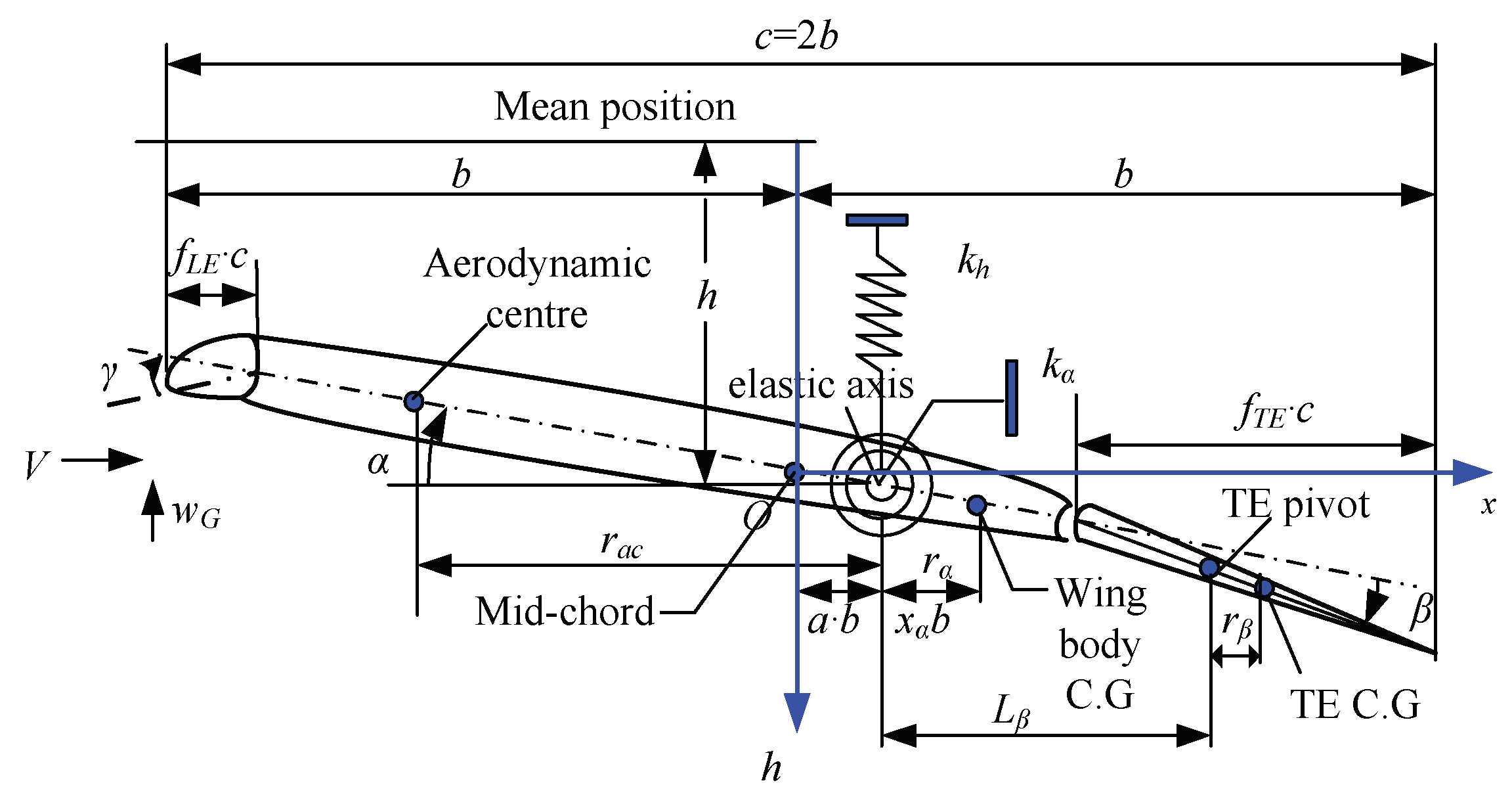
Figure 2.
Block diagram of the proposed DO-BTSMC controller.
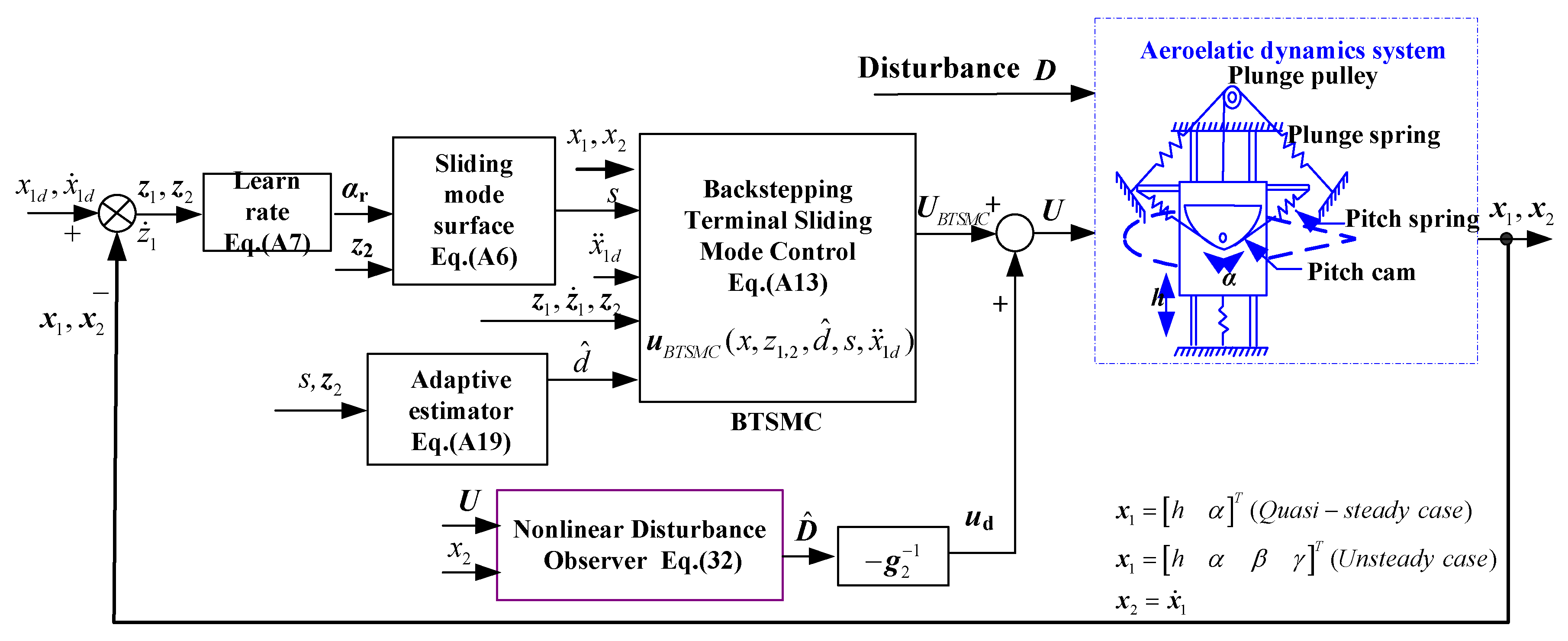
Figure 3.
Responses of the open-loop system at the airspeed of V = 11.4m/s.
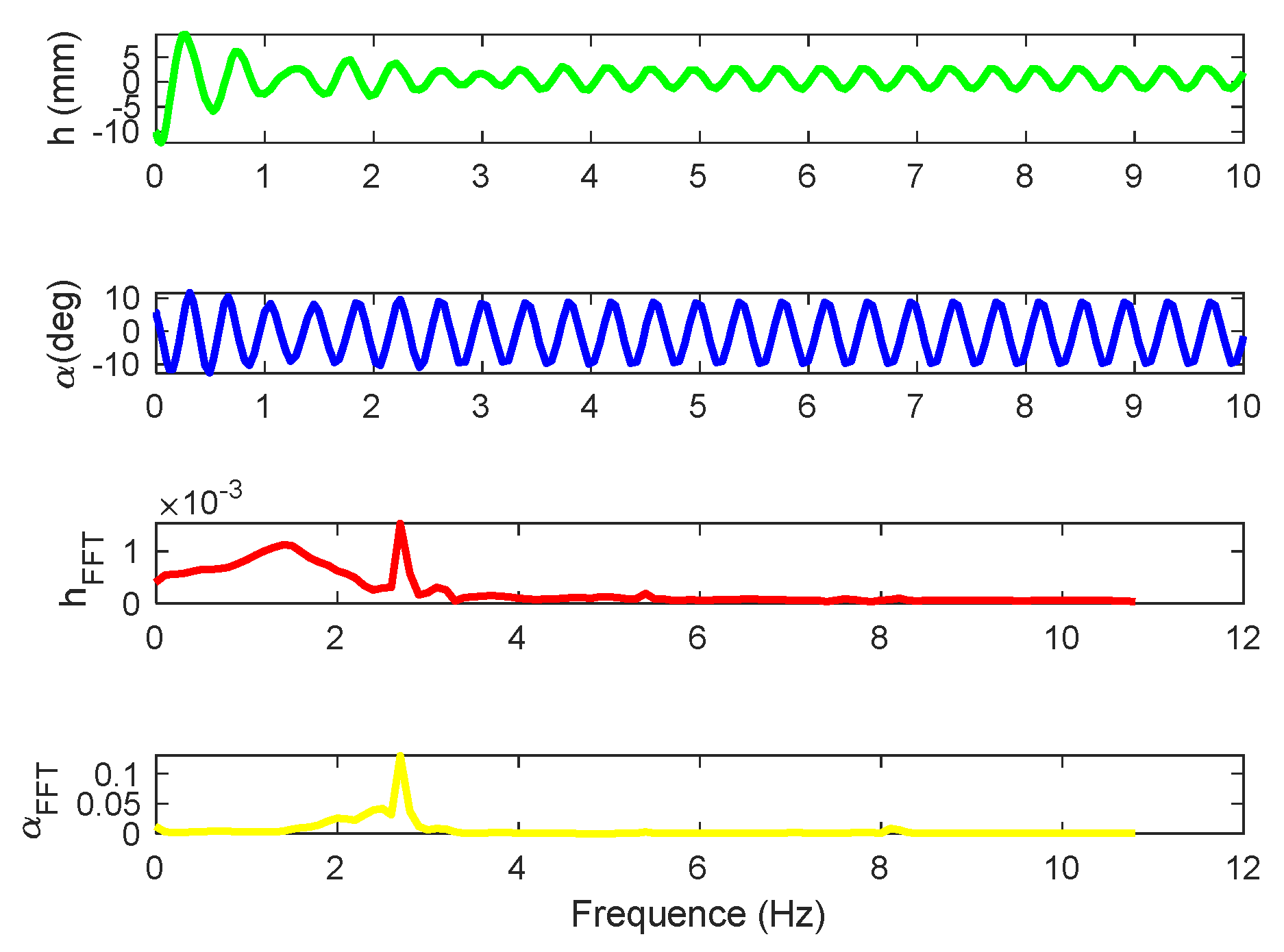
Figure 4.
Output responses of plunge and pitch motions.
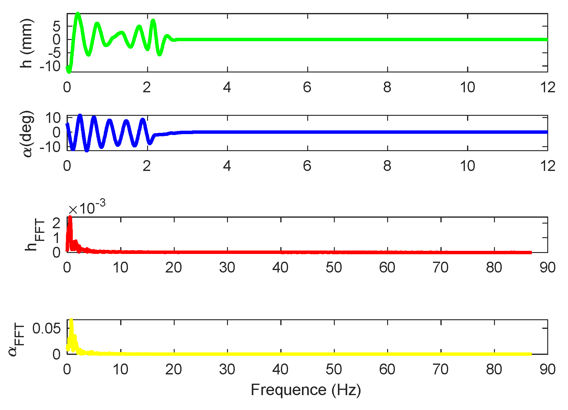
Figure 5.
Output responses of plunge and pitch motions without control (high stiffness).
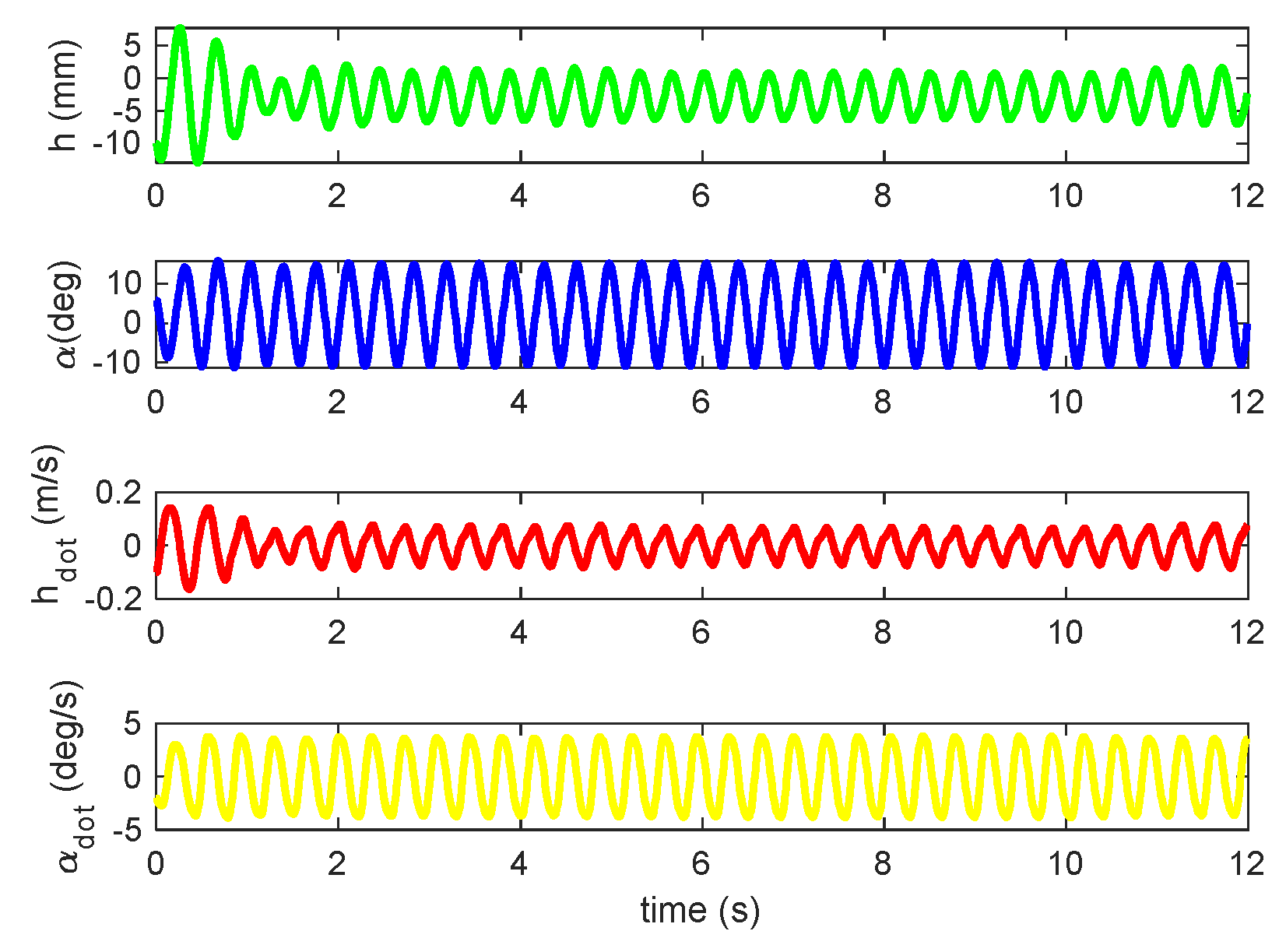
Figure 6.
Output responses of plunge and pitch motions with control inputs (high stiffness).
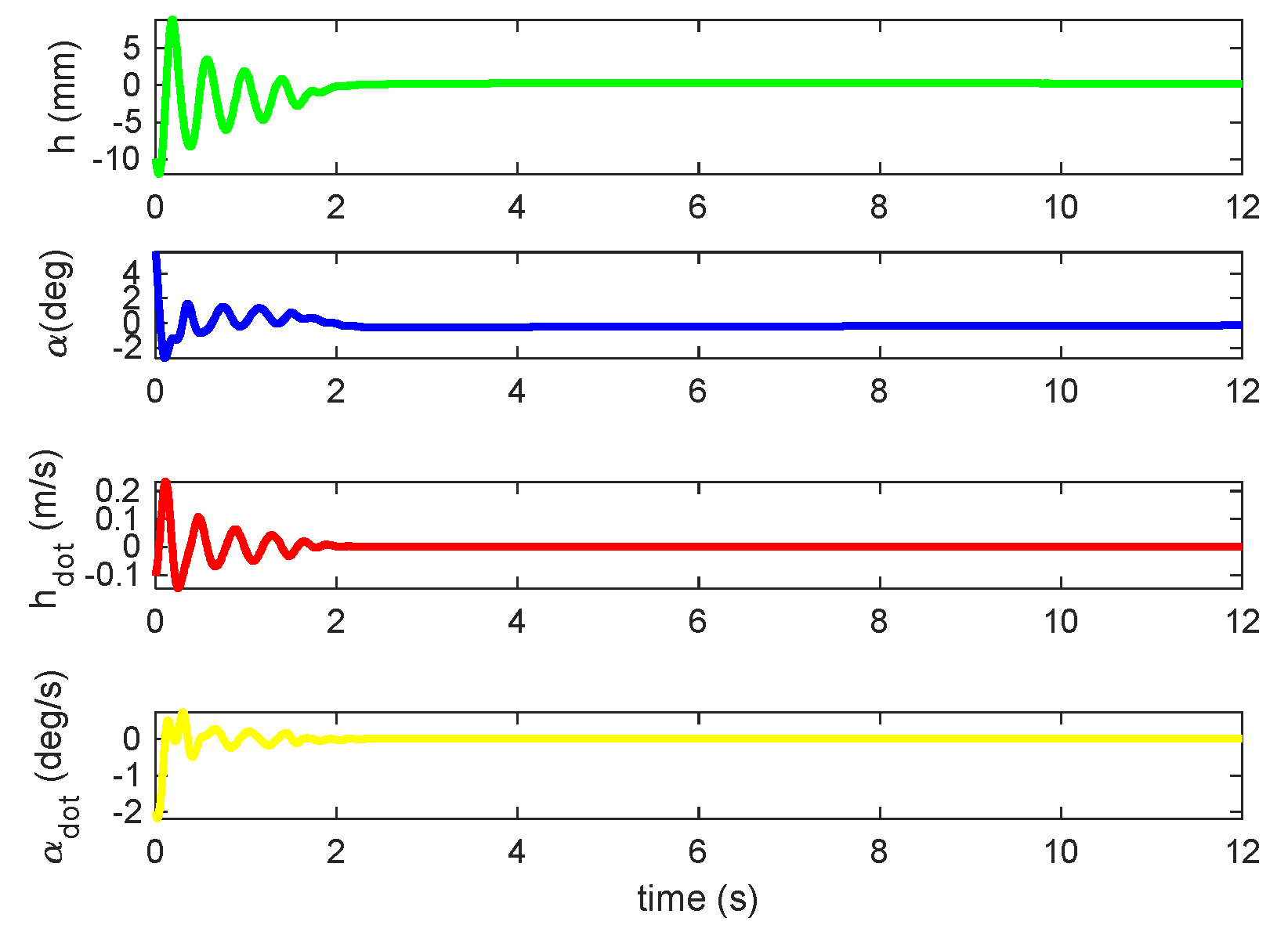
Figure 7.
Output responses of plunge and pitch motions under 10deg AOA command.
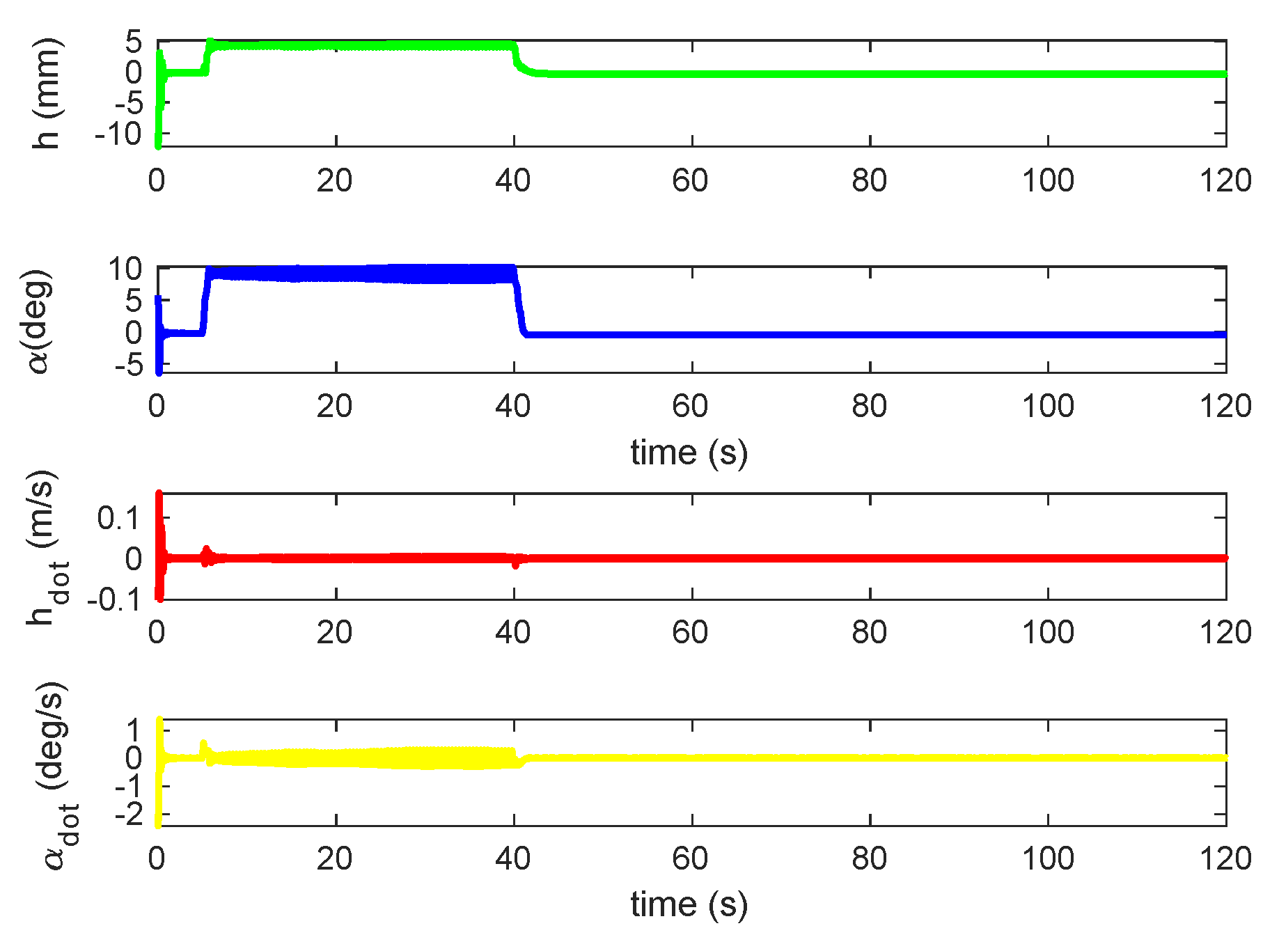
Figure 8.
Responses of plunge and pitch under triangular gust with quasi-steady aerodynamic loads.
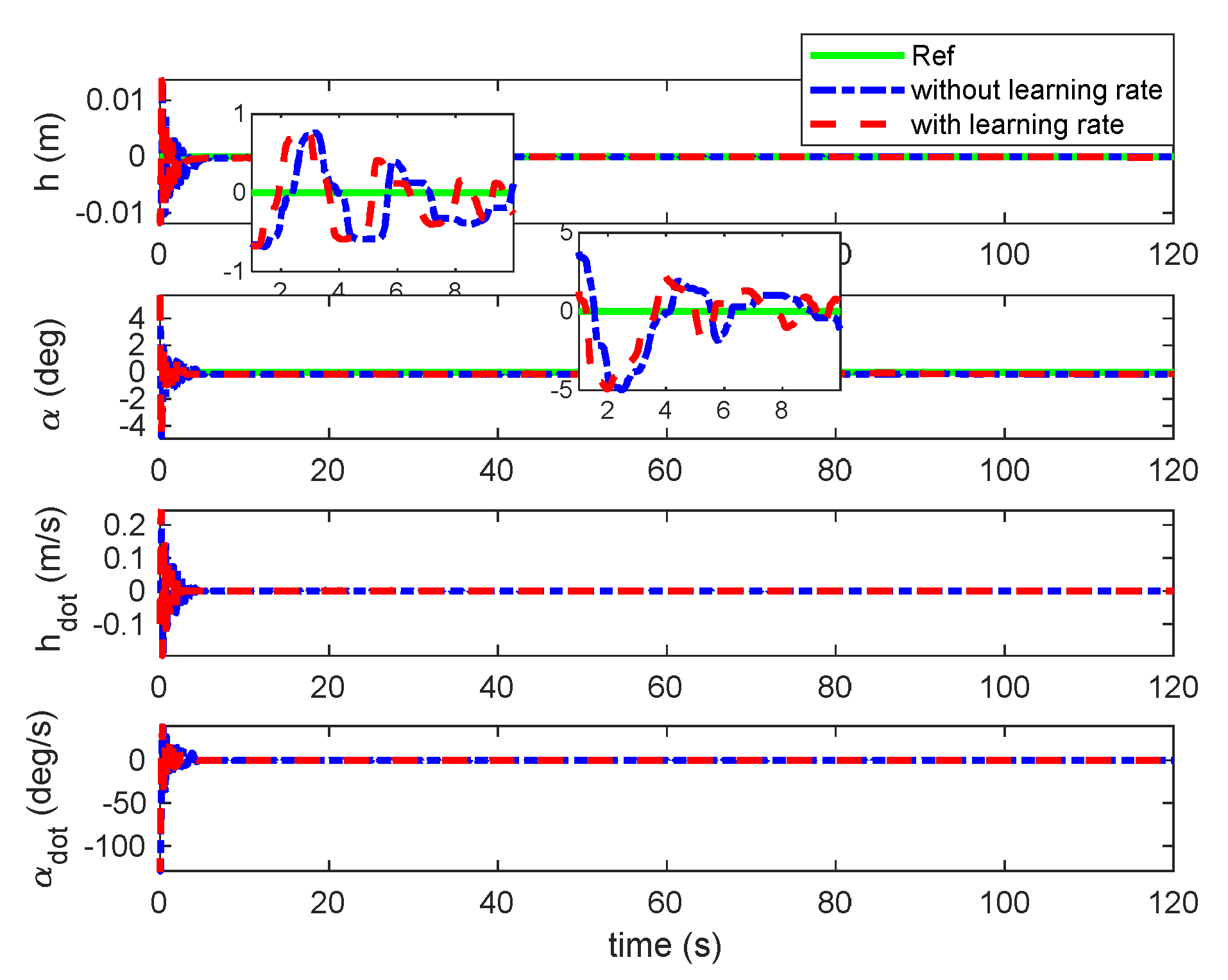
Figure 9.
Deflection of TE and LE control under triangular gust with quasi-steady aerodynamic loads.
Figure 9.
Deflection of TE and LE control under triangular gust with quasi-steady aerodynamic loads.
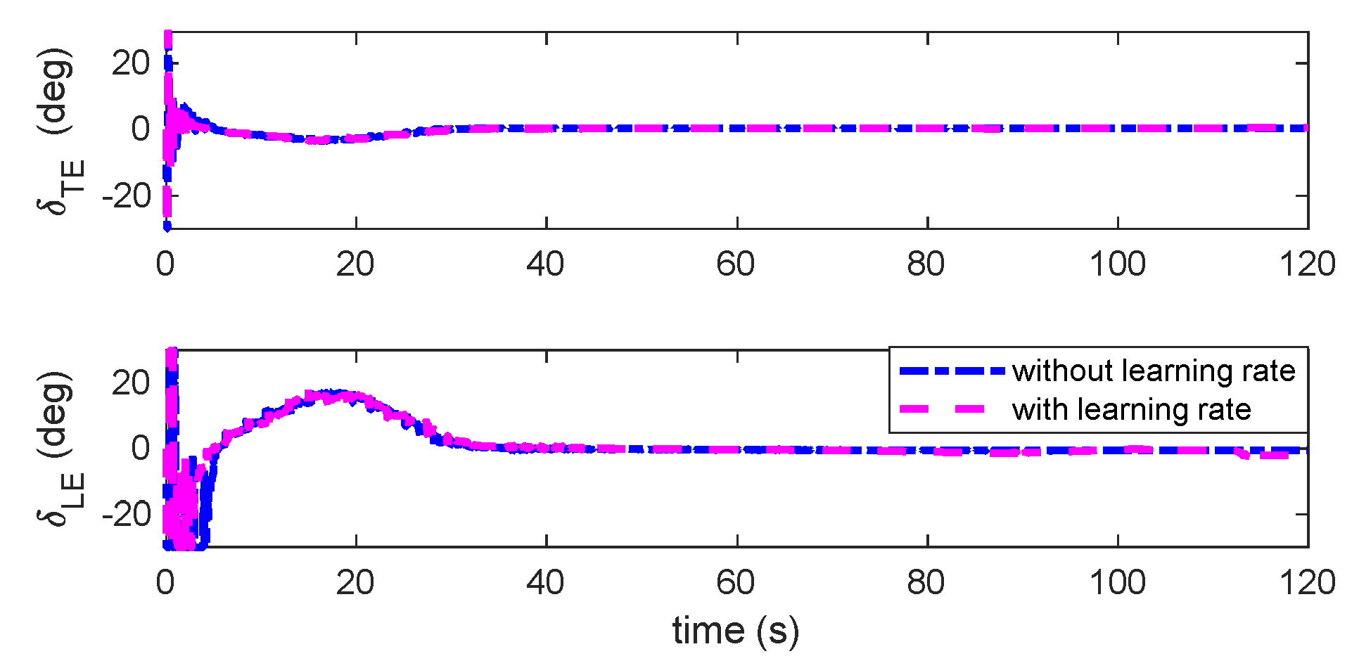
Figure 10.
Output responses of plunge and pitch under sine gust with quasi-steady aerodynamic loads.
Figure 10.
Output responses of plunge and pitch under sine gust with quasi-steady aerodynamic loads.
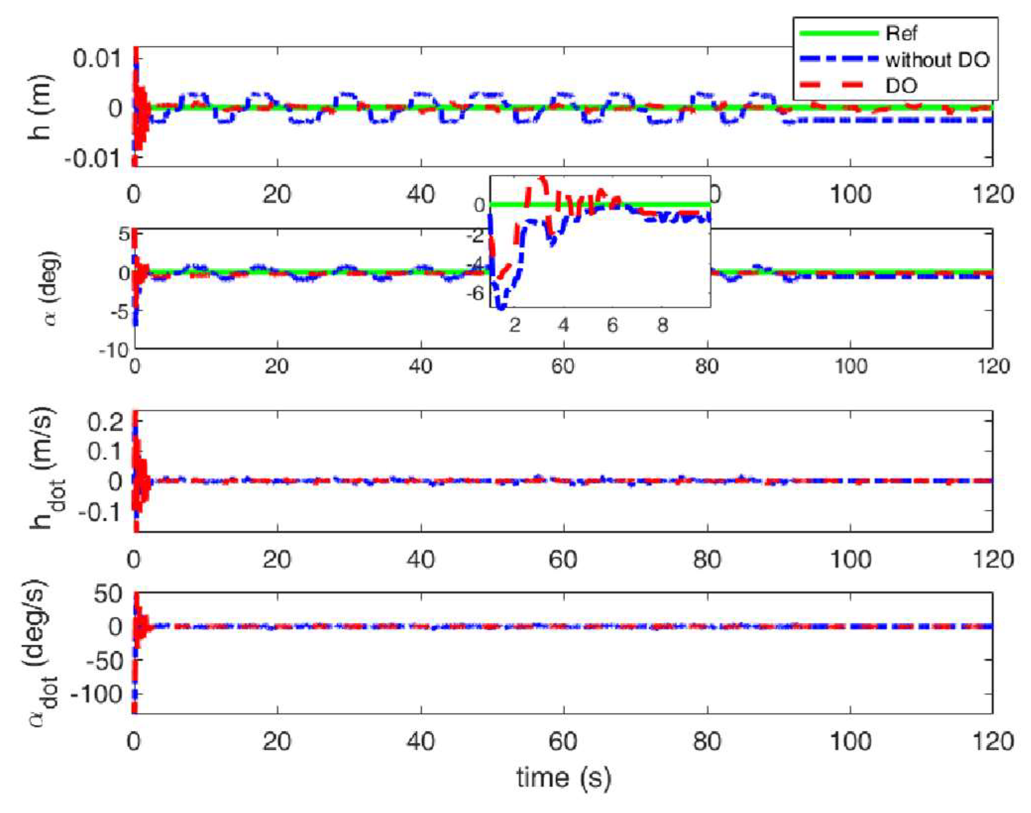
Figure 11.
Deflection of TE and LE control under sine gust with quasi-steady aerodynamic loads.
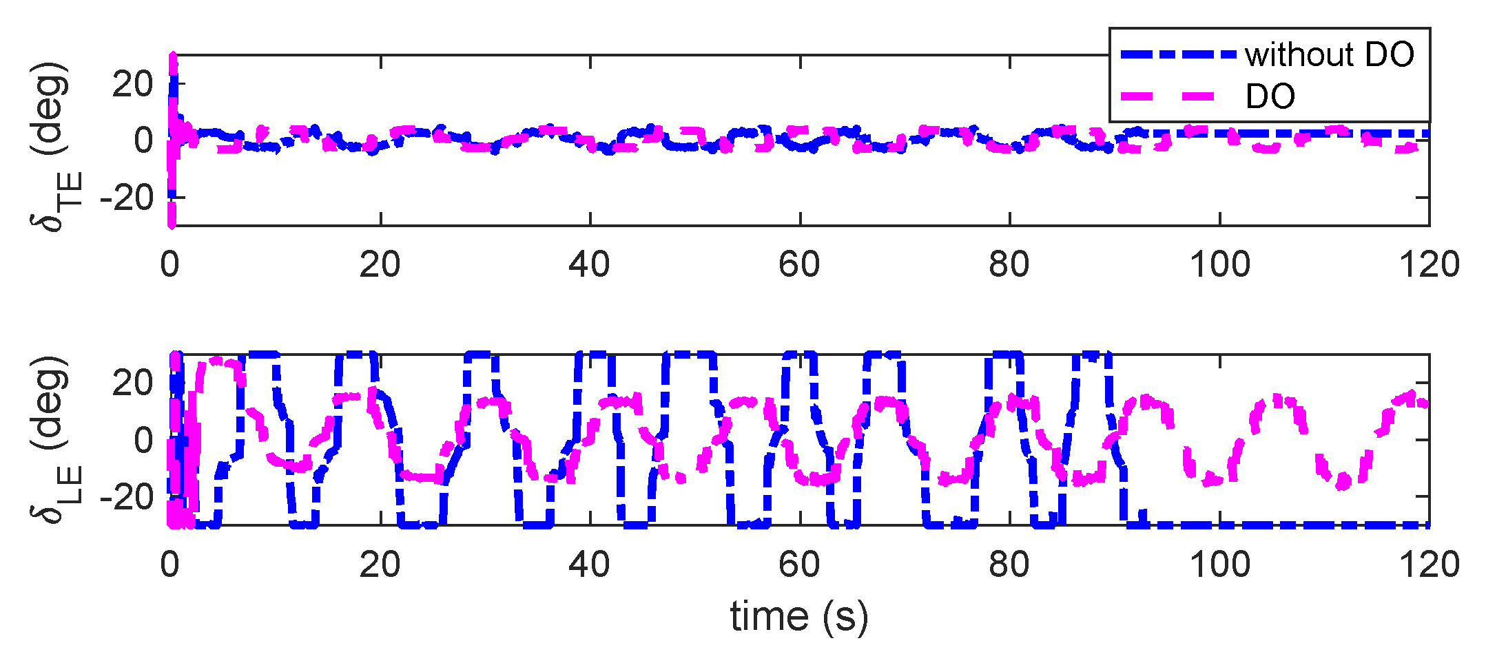
Figure 12.
Responses of plunge and pitch under triangular gust with quasi-steady aerodynamic loads.
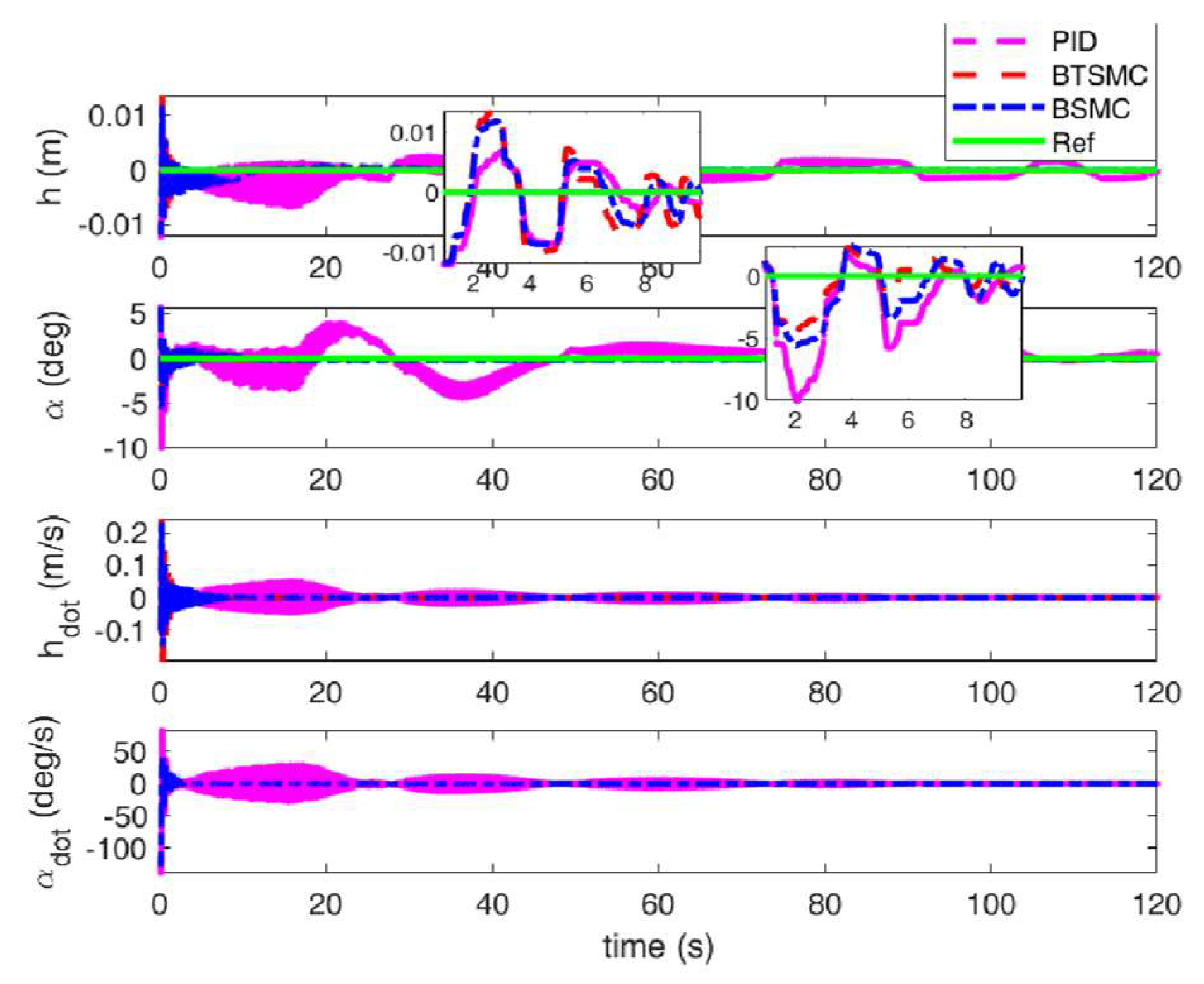
Figure 13.
Observable disturbances estimation under triangular gust.
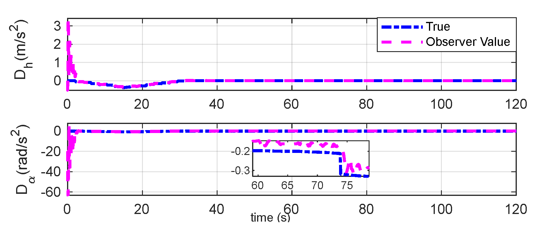
Figure 14.
Unobservable disturbances estimation under triangular gust.
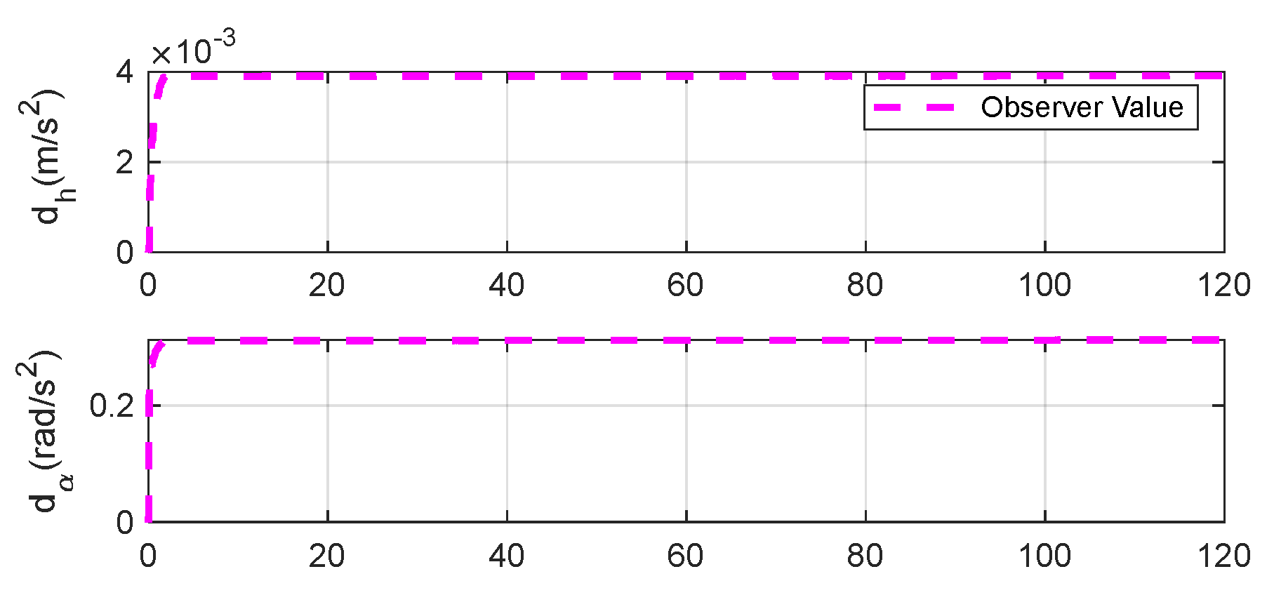
Figure 15.
Responses of plunge and pitch under triangular gust with unsteady aerodynamic loads.
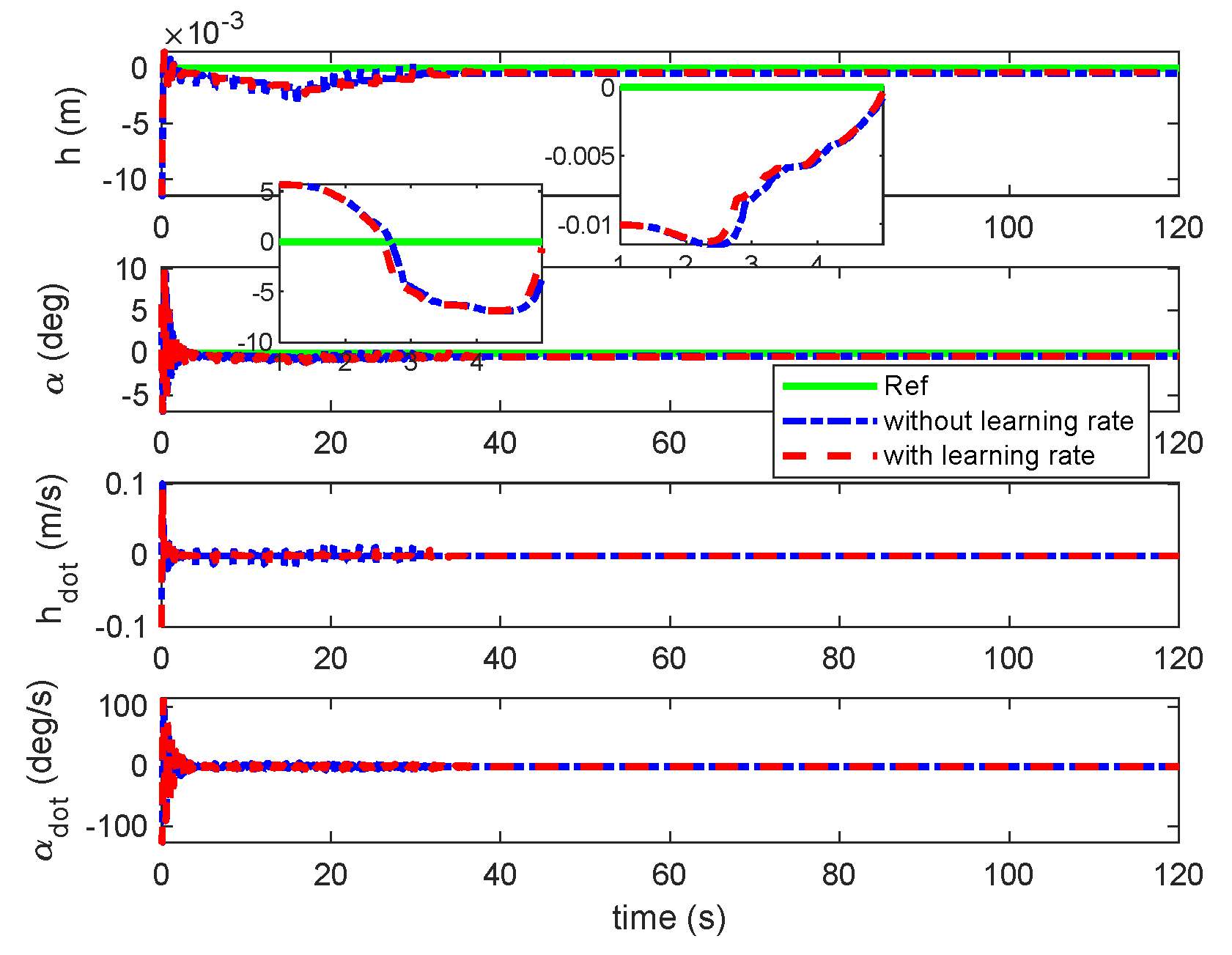
Figure 16.
Responses of β and γ under triangular gust with unsteady aerodynamic loads.
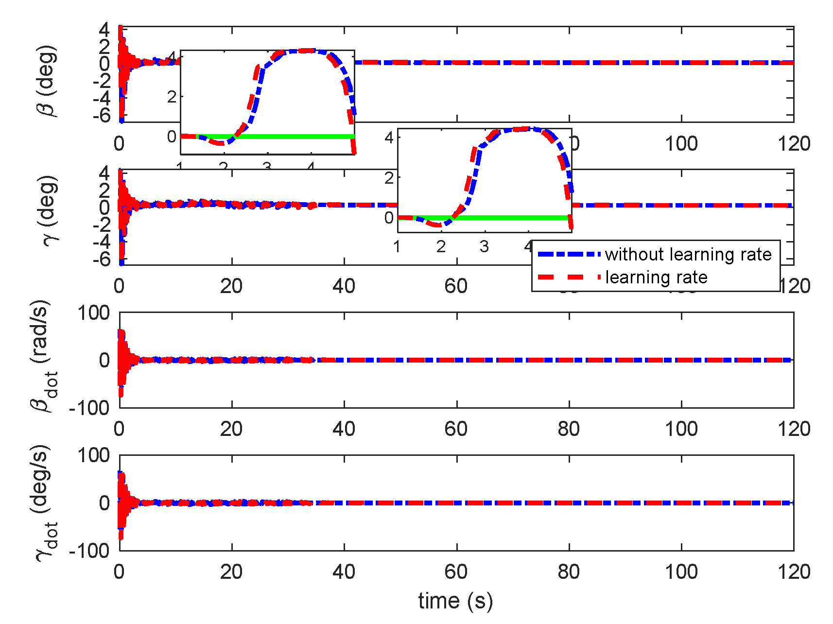
Figure 17.
Responses of aerodynamic states under triangular gust with unsteady aerodynamic loads.
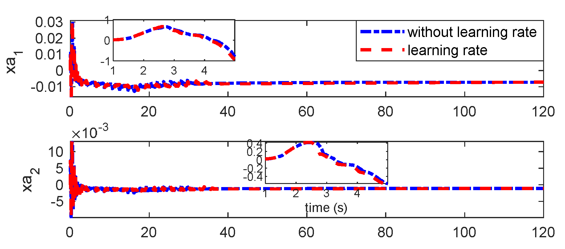
Figure 18.
Deflection of TE and LE control under triangular gust with unsteady aerodynamic loads.
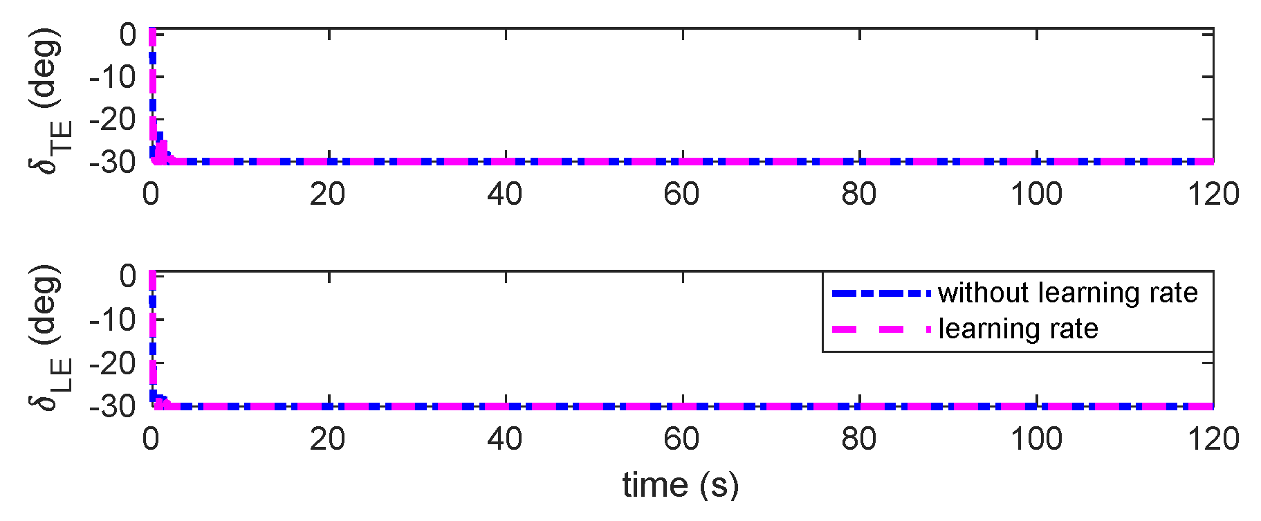
Figure 19.
Disturbances estimation under triangular gust by DO.
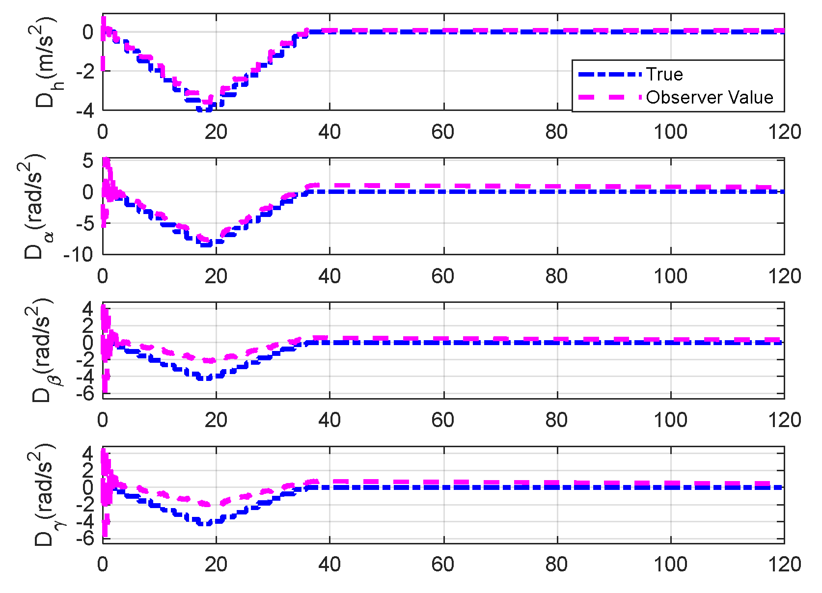
Figure 20.
Output responses of plunge and pitch under sine gust with unsteady aerodynamic loads.
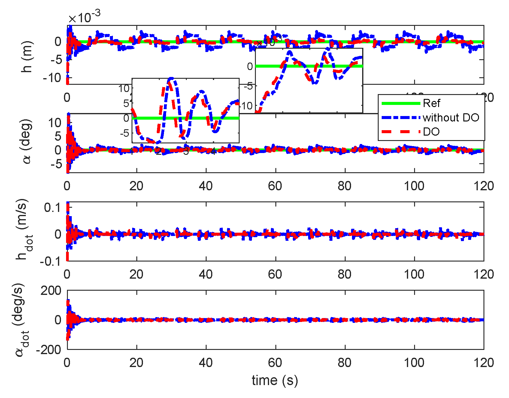
Figure 21.
Responses of β and γ under sine gust with unsteady aerodynamic loads.
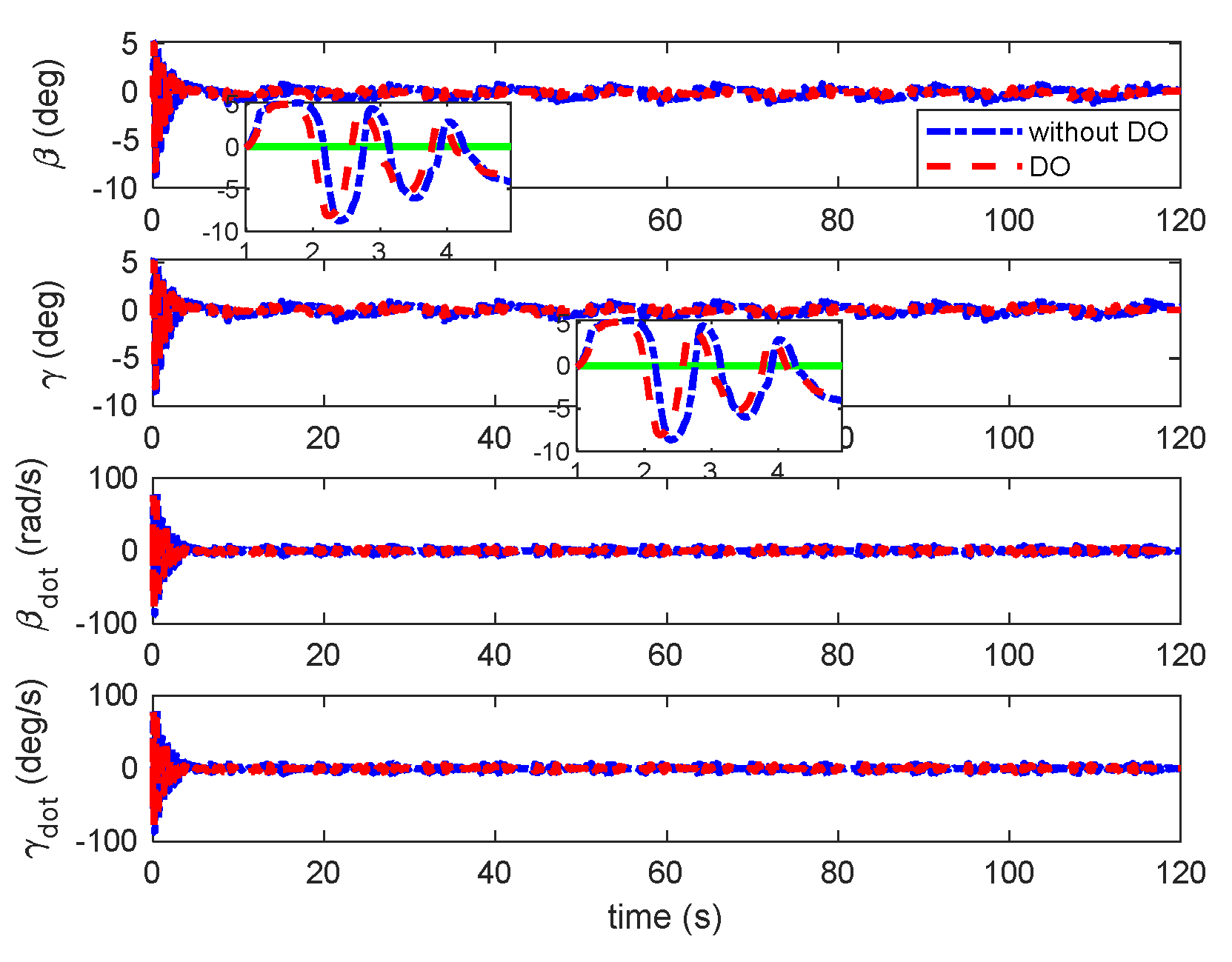
Figure 22.
Responses of aerodynamic states under sine gust with unsteady aerodynamic loads.
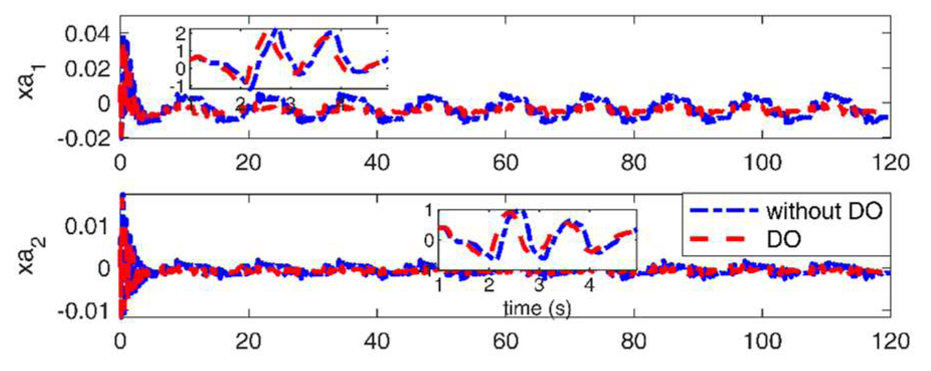
Figure 23.
Deflection of TE and LE control under sine gust with unsteady loads.
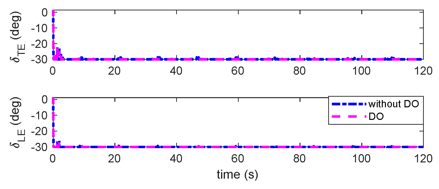
Figure 24.
Responses of plunge and pitch under sine gust with quasi-steady aerodynamic loads.
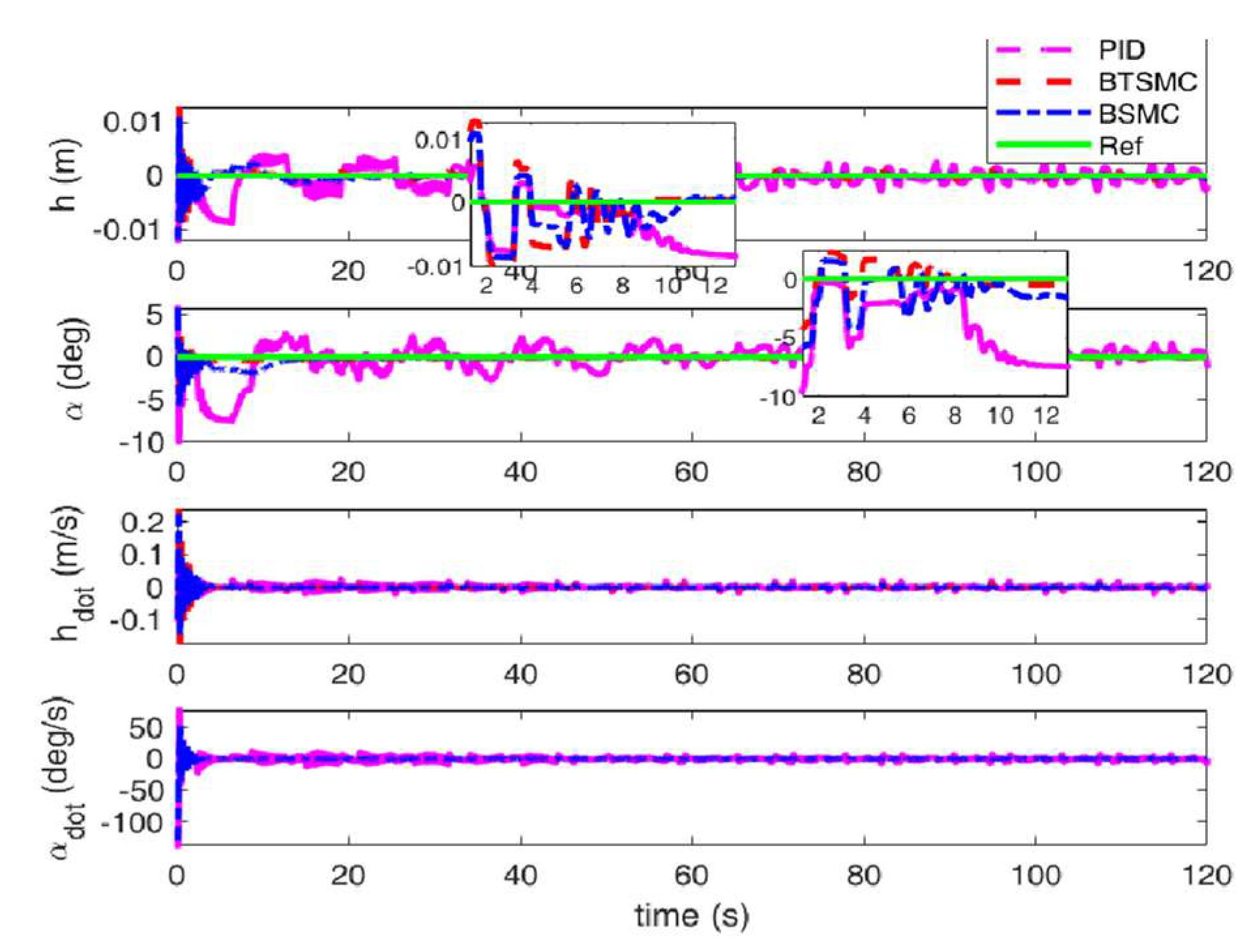
Figure 25.
Observable disturbances estimation under sine gust with quasi-steady aerodynamic loads.
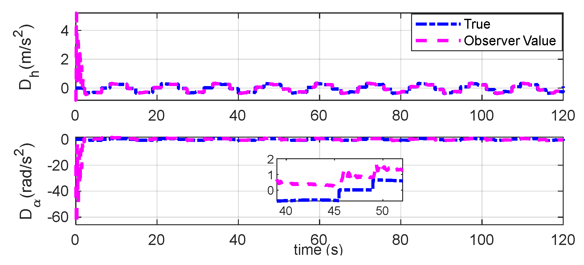
Figure 26.
Unobservable disturbances estimation under sine gust with quasi-steady aerodynamic loads.
Figure 26.
Unobservable disturbances estimation under sine gust with quasi-steady aerodynamic loads.
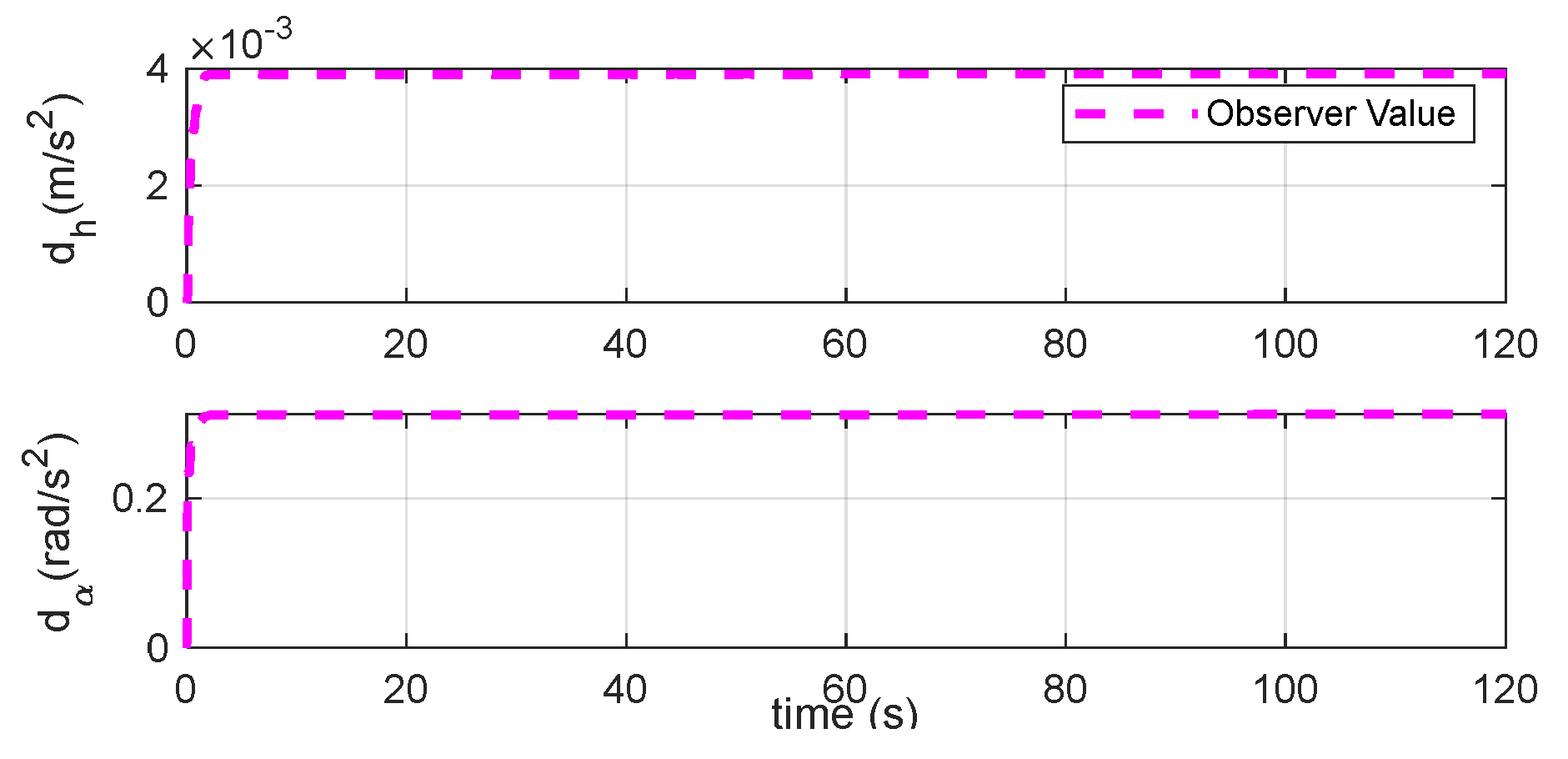
Figure 27.
Deflection of TE and LE control under sine gust with quasi-steady aerodynamic loads.
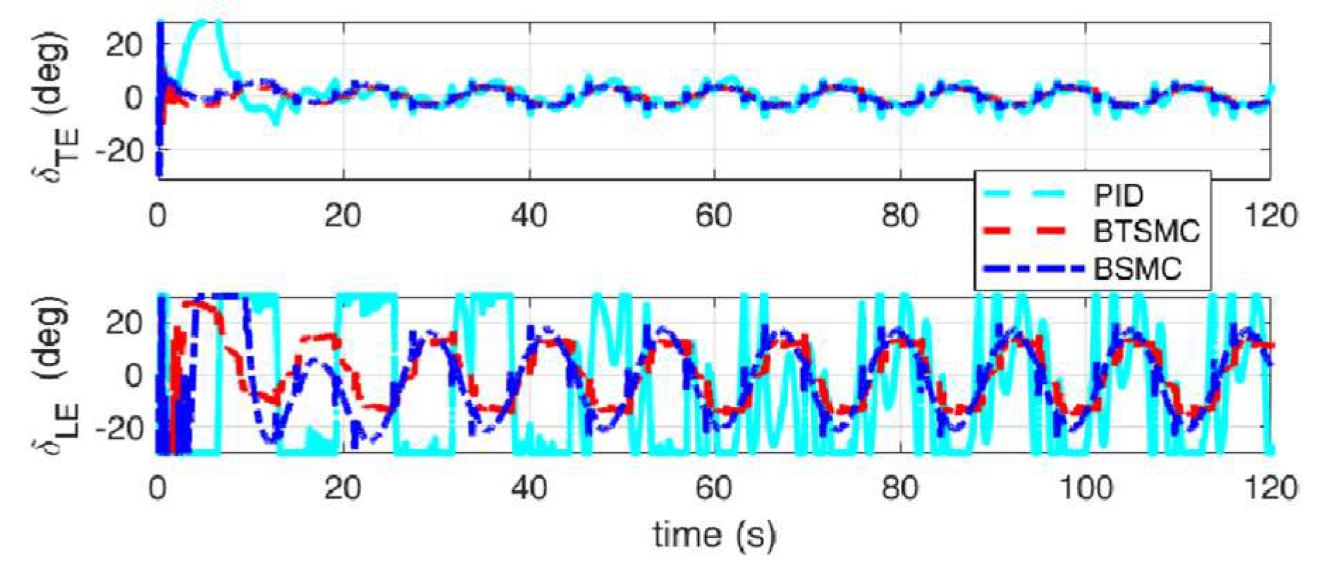
Figure 28.
Responses of plunge and pitch under sine gust with unsteady aerodynamic loads.
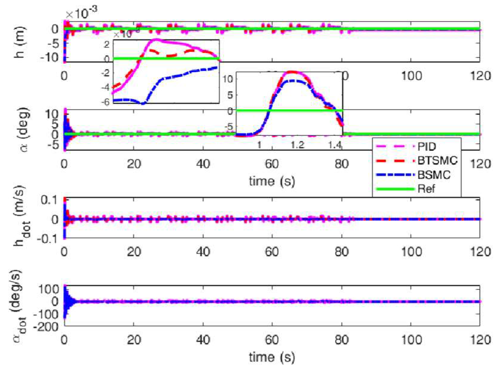
Figure 29.
Responses of β and γ under under sine gust with unsteady aerodynamic loads.
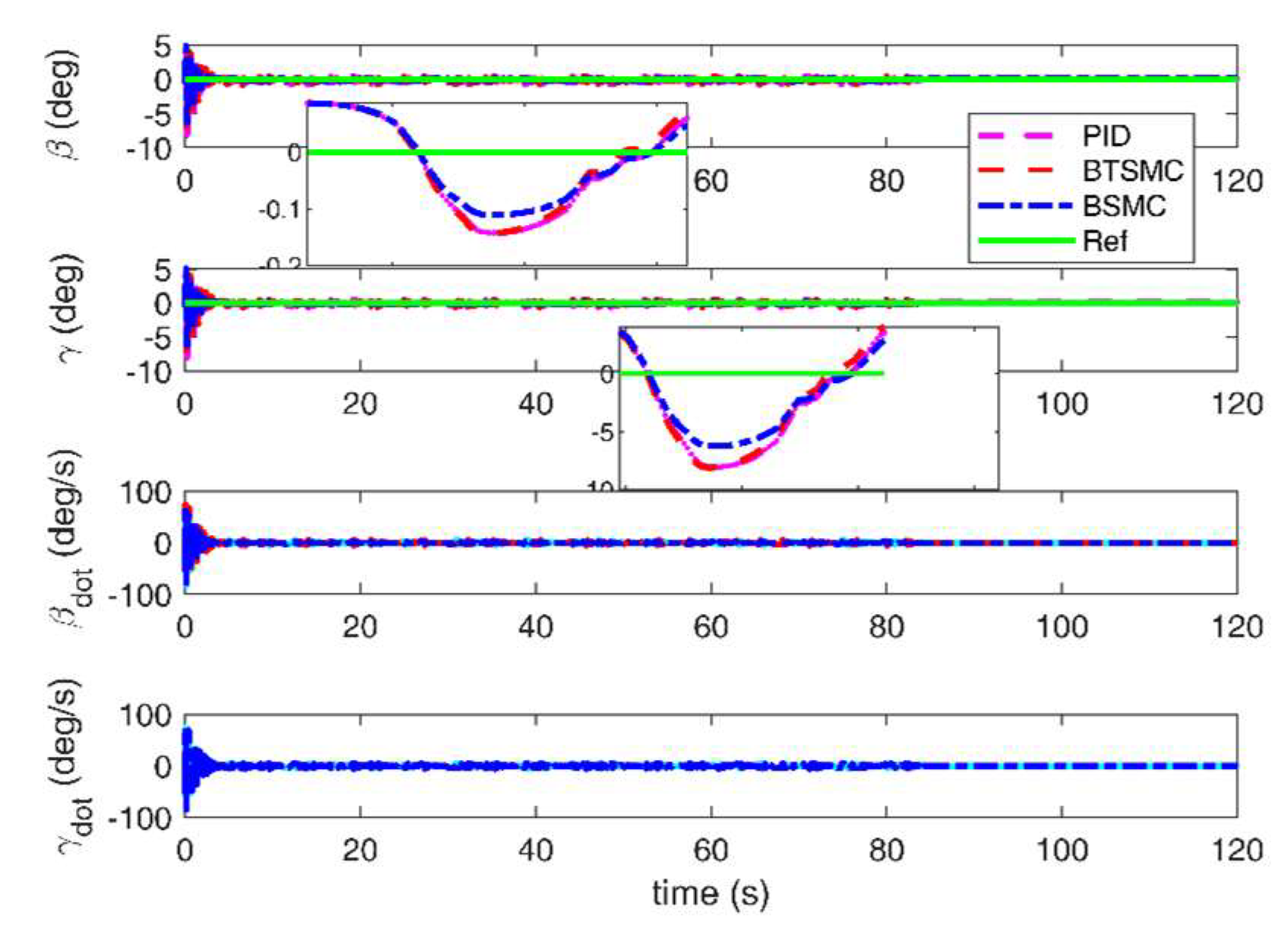
Figure 30.
Responses of aerodynamic states under sine gust with unsteady aerodynamic loads.
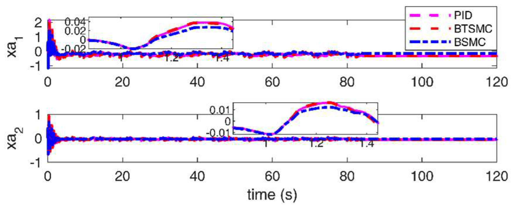
Figure 31.
Observable disturbances estimation under sine gust with unsteady aerodynamic loads.
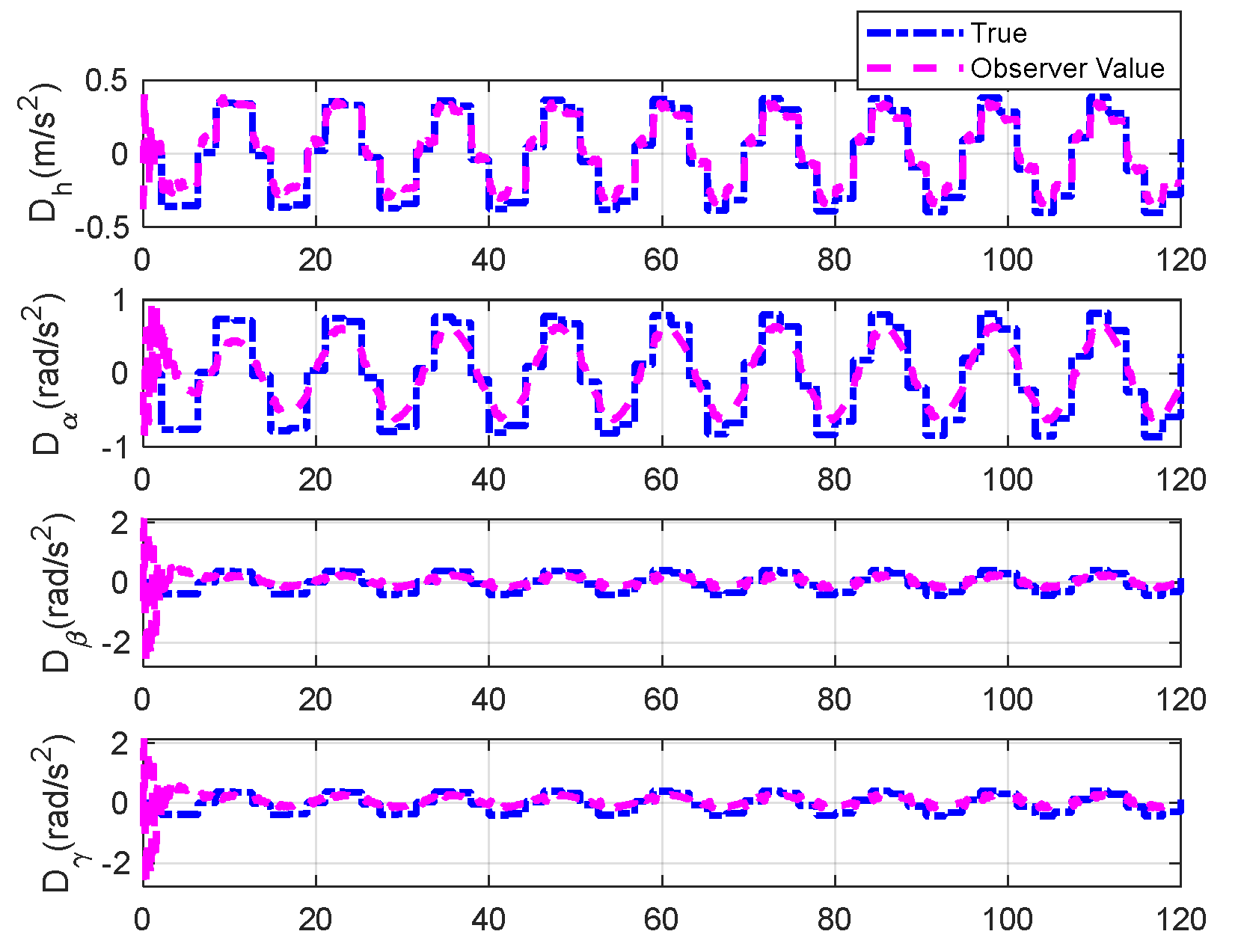
Figure 32.
Unobservable disturbances estimation under sine gust with unsteady aerodynamic loads.
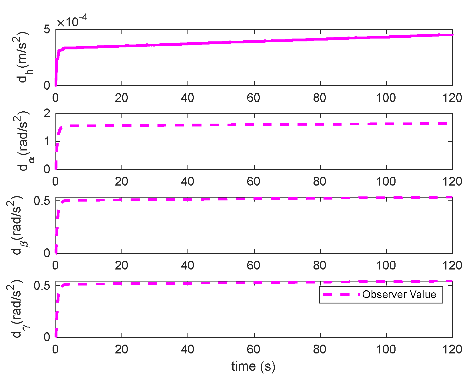
Figure 33.
Deflection of TE and LE control under sine gust with unsteady aerodynamic loads.
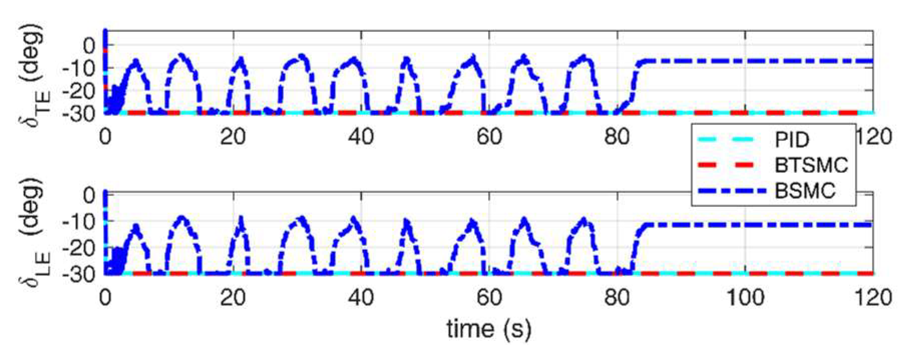

Table 1.
Parameters of the two-dimensional wing.
| Quasisteady aerodynamic model | Unsteady aerodynamic model | ||
|---|---|---|---|
| Parameter | Value | Parameter | Value |
| mwing | 4.34 kg | mh | 6.815kg |
| mW(total) | 5.23 kg | mα | 5.715kg |
| mT | 15.57 kg | mβ | 0.537kg |
| sp | 0.5945m | mγ | 0.5kg |
| b | 0.1905m | Iα | 0.119kg.m2 |
| a | −0.6719 | Iβ | 1e-5 kg.m2 |
| c | 0.381m | Iγ | 1e-5 kg.m2 |
| ICG.wing | 0.04342 kg⸱m2 | rα | 0.040m |
| Icam | 0.04697 kg⸱m2 | rβ | 0 |
| ch | 27.43 kg/s | rγ | 0 |
| cα | 0.0360kg⸱m2/s | rac | -0.033m |
| ρ | 1.225kg/m3 | r3/4c | 0.233m |
| rcg | −b(0.0998+a) | Lβ | 0.233m |
| CLα | 6.757 | Lγ | -0.01m |
| CLβ | 3.774 | kβs | 766.08 Iβ |
| Cmα | 0 | cβs | 41.82 Iβ |
| Cmβ | −0.6719 | kγs | 530.24 Iγ |
| CLγ | −0.1566 | cγs | 44.27 Iγ |
| Cmγ | −0.1005 | cα | 0.205Nm.s/rad |
| kh | 2844N/m | ch | 27.43 Nm.s/rad |
| xα | rcg/b m | ωnβs | 27.68 rad/s |
| fLE | 0.15 | ζβs | 0.7555 |
| fTE | 0.2 | ωnγs | 23.03 rad/s |
| Iα | Icam +ICG.wing +mwing(rcg)2 kg⸱m2 | ζγskh | 0.9612844N/m |
| kα | 12.77+53.47α+1003α2Nm/rad | kα | 27.96-167.63α+552.55α2+1589.3α3-3247.2α4 |
Table 2.
Selected parameters of the controller (Quasi-steady case).
| Controller | parameters | Value |
|---|---|---|
| PID | kp,z1, ki,z1, kp,z2, ki,z2 | diag(0.1,0.1), diag(0.1,0.1), diag(1,1),diag(0.4,0.4) |
| BTSMC | The same as Section4.1 | |
| BSMC | K1, λ1 | diag(0.4,0.2),diag(0.5,0.5) |
| hs, ς | diag(0.5,0.5), diag(50, 30) | |
| φs, βs | 0.4, 1 |
Table 3.
Performance comparative data under triangular and sine gusts.
| Gust input | Controller | Data | Rising time(s) | Over-shoots | RMSE |
|---|---|---|---|---|---|
| Triangular gust(Case I, Example 1) | No LR (with DO) | h | 0.1770 | 0.0134 | 0.0023 |
| α | - | - | 0.0129 | ||
| LR (with DO) | h | 0.1187 | 0.0136 | 0.0022 | |
| α | - | - | 0.0120 | ||
| Sine gust(Case I, Example 2) | No DO (No LR) | h | 0.1084 | 0.0104 | 0.0027 |
| α | - | - | 0.0160 | ||
| DO (No LR) | h | 0.1205 | 0.0124 | 0.0018 | |
| α | - | - | 0.0110 |
‘–’ denotes nonstatistical variable in Table 3.
Table 4.
Performance comparative data under triangular gust (Quasi-steady aerodynamic loads).
| Controller | Data | Rising time(s) | Over-shoots | RMSE |
|---|---|---|---|---|
| DO-PID | h | 0.1467 | 0.0067 | 0.0026 |
| α | - | - | 0.0345 | |
| DO-BTSMC | h | 0.1187 | 0.0136 | 0.0021 |
| α | - | - | 0.0120 | |
| DO-BSMC | h | 0.1215 | 0.0118 | 0.0022 |
| α | - | - | 0.0153 |
Table 5.
Selected parameters of the controller (Unsteady case).
| Controller | parameters | Value |
|---|---|---|
| PID | kp,z1, ki,z1, kp,z2, ki,z2 | diag(0.1,0.1,0.1,0.1), diag(0.1,0.1,0.1,0.1), diag(1,1,1,1),diag(0.4,0.4, 0.4, 0.4) |
| BTSMC | K1, λ1 | K1=diag(0.2,0.1,0.1,0.1), λ=1.8*diag(1,1,1,1). |
| p, q | 5, 3 | |
| β, α0, β1 | β=diag(1,1,1,1), α0=10, β1=3, | |
| hs, ς | hs=diag(0.5,0.5,0.5,0.5), ς=diag(30,50, 30, 30), | |
| φs, βs | φs=0.4,βs=1 | |
| BSMC | K1, λ1 | diag(0.2,0.1,0.1,0.1),diag(0.5,0.5,0.5,0.5) |
| hs, ς | diag(0.5,0.5,0.5,0.5), diag(30,50, 30, 30) | |
| φs, βs | 0.4, 1 |
Table 6.
Performance comparative data under triangular and sine gusts with unsteady aerodynamic loads.
Table 6.
Performance comparative data under triangular and sine gusts with unsteady aerodynamic loads.
| Gust input | Controller | Data | Rising time(s) | Over-shoots | RMSE |
|---|---|---|---|---|---|
| Triangular gust(Case II, Example 3) | No LR (with DO) | h | 0.2438 | 0.0010 | 0.0022 |
| α | - | 0.1758 | 0.0285 | ||
| LR (with DO) | h | 0.2278 | 0.0015 | 0.0020 | |
| α | - | 0.1782 | 0.0281 | ||
| Sine gust(Case II, Example 4) | No DO (No LR) | h | 0.1704 | 0.0045 | 0.0019 |
| α | - | 0.2312 | 0.0267 | ||
| DO (No LR) | h | 0.1447 | 0.0025 | 0.0013 | |
| α | - | 0.2144 | 0.0218 |
Table 7.
Performance comparative data under parameter uncertainty and sine gust (Quasi-steady Case).
Table 7.
Performance comparative data under parameter uncertainty and sine gust (Quasi-steady Case).
| Controller | Data | Rising time(s) | Over-shoots | RMSE |
|---|---|---|---|---|
| DO-PID | h | 0.1481 | 0.0077 | 0.0025 |
| α | - | - | 0.0447 | |
| DO-BTSMC | h | 0.1205 | 0.0124 | 0.0018 |
| α | - | - | 0.0110 | |
| DO-BSMC | h | 0.1275 | 0.0045 | 0.0014 |
| α | - | - | 0.0173 |
Table 8.
Performance comparative data under parameter uncertainty and sine gust (Unsteady Case).
| Controller | Data | Rising time(s) | Over-shoots | RMSE |
|---|---|---|---|---|
| DO-PID | h | 0.1916 | 0.0024 | 0.0017 |
| α | - | 0.2137 | 0.0199 | |
| DO-BTSMC | h | 0.1415 | 0.0025 | 0.0010 |
| α | - | 0.2147 | 0.0183 | |
| DO-BSMC | h | 1.3885 | 0.0004 | 0.0010 |
| α | - | 0.1645 | 0.0151 |
Disclaimer/Publisher’s Note: The statements, opinions and data contained in all publications are solely those of the individual author(s) and contributor(s) and not of MDPI and/or the editor(s). MDPI and/or the editor(s) disclaim responsibility for any injury to people or property resulting from any ideas, methods, instructions or products referred to in the content. |
© 2024 by the authors. Licensee MDPI, Basel, Switzerland. This article is an open access article distributed under the terms and conditions of the Creative Commons Attribution (CC BY) license (http://creativecommons.org/licenses/by/4.0/).
Copyright: This open access article is published under a Creative Commons CC BY 4.0 license, which permit the free download, distribution, and reuse, provided that the author and preprint are cited in any reuse.


