Submitted:
10 October 2024
Posted:
10 October 2024
You are already at the latest version
Abstract
This paper presents a novel method for evaluating the accuracy of orientation sensors commonly used in practical applications, utilizing measurements obtained from a commercial robotic manipulator as the reference instrumentation. The core concept of the method involves determining the rotational transformations between the robot's base frame and the sensor frame, as well as between the TCP (Tool Center Point) frame and the sensor frame, without requiring precise alignment. These transformations are assumed to be arbitrarily chosen, allowing the computation to rely solely on the logged TCP orientations and synchronized sensor measurements. The proposed approach enables systematic testing and evaluation of orientation sensing devices without necessitating exact measurement of the rotations between the sensor frame and the reference instrumentation. The method's effectiveness is demonstrated through the evaluation of an Inertial Navigation System module and the SLAM-IMU fusion capabilities of the HTC VIVE headset.
Keywords:
orientation sensing
; inertial measurement unit
; MEMS
; gyroscope
; VR headset
; robotics
1. Introduction
Orientation sensors, whether standalone or integrated into pose-tracking systems, are extensively used in drones, mobile robots, medical applications [1], and immersive visualization devices [2]. These sensors provide absolute measurements, differential rotations, or a combination of both. For instance, Inertial Navigation Systems integrate data from a gyroscope, accelerometer, and magnetometer, while 3D SLAM applications can leverage IMU data alongside odometry for precise localization and mapping.
Sensor systems with stable external reference like motion capture cameras, VR tracking devices and electromagnetic trackers provides reliable absolute orientation with moderate noise level. However, the increasingly popular MEMS-based and the so-called inside-out vision-based systems are less robust against noise, bias, drift and delay. For example, concerning MEMS sensors, Shi et al. pointed out that environmental factors, particularly ambient temperature, significantly affect the bias and drift of these sensors, which can lead to decreased orientation estimation accuracy [3]. Another analysis by Suvorkin et al. utilized the Allan deviation slope method to evaluate noise characteristics across different grades of sensors. This analysis provides insights into the stability and reliability of IMU measurements over time, which is essential for applications requiring high precision [4]. Understanding noise characteristics is crucial for interpreting IMU data accurately and ensuring its validity in practical applications.
Inside-out tracking systems, such as those used in Microsoft’s HoloLens or HTC Vive, rely on onboard cameras to track the environment and determine orientation. While these systems offer the advantage of not requiring external infrastructure, they are highly sensitive to environmental conditions, such as lighting and occlusions. A study by Zhang et al. found that inside-out tracking systems could experience substantial errors in orientation estimation when subjected to rapid movements or changes in lighting conditions [5]. Additionally, the latency introduced by image processing can lead to noticeable delays in orientation updates, impacting user experience. Similarly, a paper by Niehorster et al. on the HTC Vive’s inside-out tracking system highlighted that while the precision of tracking measurements is high, the system can experience significant offsets when tracking is temporarily lost, affecting overall accuracy [6]. Other studies using the HTV Vive tracker gives similar conslusion [7,8]. This illustrates the challenges faced by systems that rely on internal measurements compared to those that utilize stable external references.
These imperfections underlines the importance of validation methodologies that allows for precise and automatic comparisons of various sensors under multiple conditions in a repeatable way. The validation of orientation sensors relies heavily on the establishment of ground truth data. Ground truth serves as a reference against which the performance of the sensors can be assessed. Various methods for obtaining ground truth have been documented in the literature, each with its unique advantages and applications.
One of the most reliable forms of ground truth for validating IMU orientation sensors is the use of motion capture systems. These systems provide high-precision data regarding the position and orientation of subjects in three-dimensional space. For instance, Morrow et al. conducted a validation study where they compared the kinematic data obtained from a commercially available IMU system against a standard optical motion capture system [9]. Inside-out tracking systems have been validated in similar setup [7,10]. This comparative approach is widely recognized for its effectiveness if a motion capture laboratory is available.
Another approach to obtain reliable reference is the use of mechanical fixtures. The use of fixtures in experimental setups allows for controlled conditions that can significantly enhance the reliability of sensor validation processes. Bliley et al. [11] described a validation method for wearable motion-sensing devices that involved a mechanical fixture. Their approach utilized a platform rotated by a servo motor, which allowed for precise control over the orientation of the sensors being tested. This method ensured that the sensors were subjected to known and repeatable movements, facilitating accurate comparisons between the sensor outputs and the expected values. Additionally, Eastman et al. [12] highlighted the importance of using fixtures in their work on 6DOF (six degrees of freedom) object pose ground truth measurements. They employed an aluminum pose fixture along with a laser tracker to establish a reliable reference for validating sensor outputs. This combination of a rigid fixture and precise measurement tools allowed for high accuracy in determining the orientation and position of objects. Similarly, Herickhoff et al. [13], utilized a lightweight plastic fixture to hold an IMU sensor. The adaptability of such fixtures makes them valuable tools in various applications, including medical imaging and motion analysis.
These published methods are lack of the ability of providing a programmatic way to generate test motions and then analyze the results in a tractable manner. Using a robot arm as a ground truth reference would serves with important benefits: The robot arm can provide precise and repeatable movements, allowing for accurate comparisons between the sensor outputs and the known positions and orientations of the arm. This motivation has been supported by studies from the literature of the field. Schmidt and Kraft noted that accurate ground truth trajectories can be obtained when a camera is mounted on an industrial robot arm, which allows for reliable evaluations of visual SLAM (Simultaneous Localization and Mapping) algorithms [14]. Papers such as [15,16,17] exploits the benefits of robot arms in generating motion patterns for testing IMU-s. One prominent approach by Hoslip et al. uses an industrial robot to compare the performance of multiple IMU sensors simultaneously [18]. Even this methods utilizes various robotic manipulators a systematic approach to mathematically handle the geometric relations between the robot’s and the sensor’s references, has not been published.
Authors faced this unsolved issue during the experimental validation of a generic direction and orientation tracking method based on IMU Sensor, that has been published in [19]. In our former work, we proposed a mathematical framework for calibration and tracking of objects with with one functional direction (continuous rotational symmetryc case) and multiple functional directions (nonsymmetric case). This previous work has inspired the the current study which proposes a method for the validation of orientation sensors with respect to an external reference. The proposed method is agnostic to the external (reference) measurement system, but it is discussed considering a robotic arm as a robust integrated actuation and sensing device and the robotics terminology is used throughout the discussion.
In our setup, a commercial robot arm is employed for validation, providing a precise orientation reference and enabling automated testing capabilities Figure 1. This approach not only ensures high accuracy but also facilitates systematic and repeatable validation processes.
The validation of orientation sensors using any test setup introduces the challenge of dealing with different reference and target frames. The sensor initializes its own unknown reference frame and measures the orientation of a frame fixed to the sensor relative to this reference. The analogous frames of an industrial manipulator are called base frame and TCP frame respectively (see Figure 2). We can suppose that the industrial robot’s internal measurement system provides reliable position and accurate orientation information regarding the base to TCP transformation [20,21].
This paper proposes a method to approximate the rotation matrices between the base-reference and TCP-sensor frames. The computation involves two main steps: first, deriving an initial estimate using geometric principles, followed by a local optimization to minimize the impact of measurement noise and errors..
To demonstrate the method’s effectiveness, experiments were conducted using a UR16e robot [22] with two distinct sensors: the widely-used ICM20948 IMU sensor [23] and the HTC VIVE headset’s inside-out tracking system [6,24,25,26].
The paper is organized as follows: Section 2 defines the problem and introduces the relevant notations. Section 3 elaborates on the proposed calibration method. Section 4 presents experimental results obtained with various sensors and provides a comparative analysis. Section 5 outlines future research activities and potential practical applications. Finally, Section 6 summarizes the findings. The Appendix A includes details on vector and quaternion operations, along with their respective notations, as used throughout the paper. Original measurement data associated with the content of the paper can be found at [27].
2. Problem Description
In the investigated measurement setup, the orientation can be obtained from the state of the manipulator, while the sensor provides its orientation with respect to its own reference frame, see Figure 2.
In ideal case, there exist and orientations such that
for all . However, in practical scenarios, there is an error resulting from the measurement noises and the drift of the sensor.
In the followings, the value (read from the robot controller) will be considered as ground truth. The computation of and orientations from some initial data will be referred to as calibration.
Considering the whole recorded dataset, the angle error of Eq. (1) will be analyzed to obtain the measurement noise and the drift of the sensor.
3. Calibration Method
The calibration is performed using solely the first values of the measured data. This approach enables the analysis of sensor drift in the subsequent measurements for .
The method requires at least three values from the portion of the measured data, each rotated by an angle relative to the others. Denote the time of these measurements as , , and .
The calibration process consists of two stages: first, obtaining a good initial guess using the measurements at , , and . Next, refining this initial estimate with all measurements for . The following subsections provide a detailed description of these steps.
3.1. Initial Guess
Consider the sensor pose at , and . The axis of rotation between two orientations gives a well-defined and easily obtainable common direction for both the sensor and the TCP.
For this, compute the direction of axes as
if the computation results in a negative angle, flip the direction of . (The computation requires that , and angle of and to be as close to the right angle as possible.) Furthermore, vectors , and can be computed similarly.
Then, these values can be obtained by and frames as
Now the and directions are known by all frames; the following orthogonal directions can be defined based on them:
that constructs a frame denoted by i. The method and the resulting frame are illustrated in Figure 3.
Determining these base vectors from the vectors given by the frame, the rotation matrix between the frames and i can be described as
It can also be computed for frames , and as , and .
Then the initial guess for quaternions and can be computed as
3.2. Local Optimization
The previous step provided a good calibration for the three selected measurements. The local optimization step refines this calibration by taking into account all measurements for .
The correction of the orientations is defined with Roll-Pitch-Yaw variables ()
where small angles are assumed due to the good initial guess.
With this correction term, the quaternions can be defined as
According to the parameters and , the measurements can be evaluated as
then the error of the measurement can be computed as the angle of a quaternion
where
Based on this derivation, this optimization problem can be written as
where a Nelder-Mead optimization can be used initialized from , .
From the resulted , vectors, the error of a measurement can be written as
4. Experimental Demonstration
This section presents examples of validating various orientation sensors using a UR16e manipulator [22] with the proposed method. The results provide a straightforward comparison of the devices’ performance. We investigated two sensors, a MEMS-based IMU sensor and the HTC VIVE VR headset equipped with 6 DoF tracking capabilities (so-called inside-out tracking).
4.1. ICM20948 IMU with Disabled Magnetometer
The IMU sensor ICM20948 [23] used in the experiment integrates gyroscope, magnetometer, and accelerometer units in a single package. For this measurement, the magnetometer was turned off because of the disturbing magnetic field of the manipulator. It was found that the micro-vibrations of the manipulator can influence the performance of the sensor to a considerable extent causing noise and drift in the output signal. For this reason, the sensor was attached to the manipulator in silicon bedding instead of using a rigid mounting fixture.
Furthermore, the effect of these vibrations was also diminished by applying a higher robot speed (2-4[cm]/step). Figure 4 shows the path of the manipulator. After an initial motion phase, it performs five full circles. The figure also shows the orientation in each measurement point with red line segments in the x direction and blue segments in the z direction.
First, three measurements (samples recorded at , , and ) must be chosen as close to perpendicular as possible.
It was obtained by performing the following optimization:
where in optimal case , so the angles are perpendicular.
On the initial phase of the path, the procedure automatically looks for three measured orientations that are inclined at least 60 degrees and less than 120 degrees relative to each other (In this case, their indices were , and ). The angle difference between the orientations are and . Furthermore, the angle of and is , because of the initial path segment, is almost zero.
With the results of calibration, the error of the orientation of the IMU sensor (considering the robot as a reference) can be computed, and it is plotted to Figure 5 with blue. The histogram of the error is plotted in Figure 6. They show well that the error is mostly below , and by plotting the magnitude of rotations between the measurements (by red in Figure 5), it is easy to see that significant errors are only measured during fast rotations. These errors are partially caused by the unavoidable time difference between signal processing in the robot and the sensors that result in a certain time delay between the parallel orientation samples.
4.2. HTC VIVE (IMU and SLAM Sensor-Fusion Using 6 Cameras)
The HTC VIVE Cosmos headset uses six cameras and an IMU unit for its SLAM algorithm and can be considered a cutting-edge inside-out tracking technology. The headset was fixed to the flange of the manipulator and was moved on the path plotted in Figure 4, without the initial segment. Because it was not sensitive to vibrations of slow robot motions, two rounds were recorded at different speeds.
In this case, an automatic search was also applied to obtain orientation samples with angle between them. The indices of the chosen measurements were , and , the angles between them are and . Furthermore, the angle of and is , so in this case .
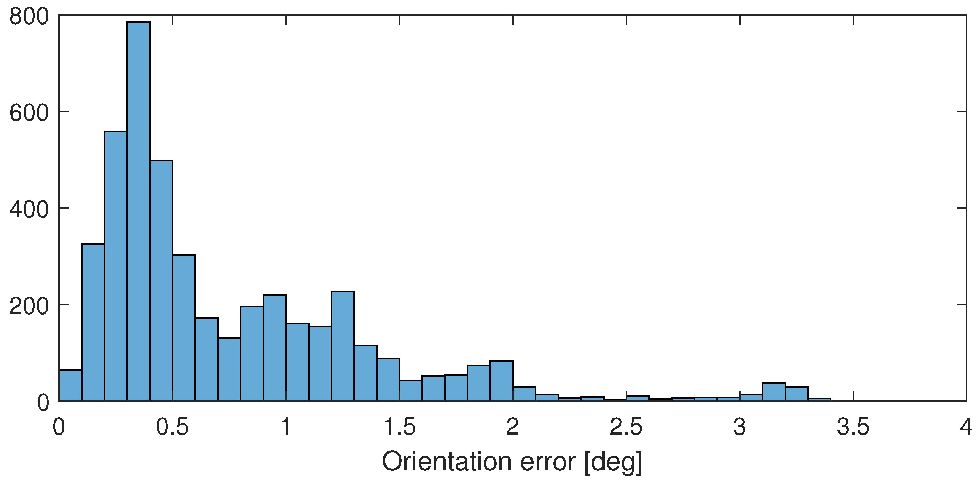
After performing the calibration method described in Section 3, the computation results in errors plotted in Figure 7 with blue, and in histogram of Figure 8. The figures show that the error is mostly below . The rotation angle between the measurements is also plotted in Figure 7 with red, and it shows well that the larger differences between the sensors are measured only if the device is rotating.
5. Future Work
Concerning the further research two directions are considered. The first goal is performing experimental work on the validation of standalone 6DoF tracking sensors, like [28] on a similar robotic setup extending the investigation to positioning accuracy. The other research direction aims to apply the presented approach for the geometric calibration of manipulators as well as the real-time monitoring of the consistency between the joint trajectory and the Cartesian trajectory of robot manipulator with known kinematic model. Such a monitoring method can be beneficially applied in mission critical medical robotic systems e.g., the CyberKnife [29].
6. Conclusion
The paper proposed a generic method to validate orientation sensors using an independent reference of higher accuracy. The method has two main steps. First, a good initial guess is computed via simple geometric computation, which is followed by a refinement via local optimization starting from the previously computed initial guess. The method is presented in a generic manner enabling the application with any kind of programmable manipulator and the associated orientation measurement instrumentation. Commercial robot arms are compact and reliable devices suitable for this purpose. The main benefits of the proposed method includes the repeatable excitation pattern that allows for the comparison of various orientation sensors under the same conditions regarding the orientation trajectory, external disturbances, visual environment, etc. The method is illustrated by validating an IMU (ICM20948) and a complex inside-out tracking system (HTC VIVE Cosmos) an UR 16e manipulator. The experiments has been shown that concerning the investigated sensors, significant orientation errors only occur at larger angular velocities.
Author Contributions
Conceptualization, Péter Galambos; methodology, József Kuti, Péter Galambos; software, József Kuti, Tamás Piricz; validation, József Kuti; formal analysis, József Kuti; investigation, József Kuti, Tamás Piricz and Péter Galambos; resources, Péter Galambos; data curation, József Kuti; writing—original draft preparation, József Kuti; writing—review and editing, Péter Galambos; supervision, Péter Galambos; All authors have read and agreed to the published version of the manuscript.
Funding
Péter Galambos is supported by the ÚNKP-23-5 (Bolyai+) New National Excellence Program of the Ministry for Innovation and Technology from the source of the National Research, Development and Innovation Fund. Péter Galambos is a Bolyai Fellow of the Hungarian Academy of Sciences.
Appendix A
The orientations will be described via unit quaternions. The main operations for their usage are discussed here. Denote the unit quaternion as
where . The related rotation matrix can be written as
The quaternion form a rotation matrix can be computed via the Stephenson-formula, see [30]. The quaternion of a rotated orientation around axis by angle is
and its opposite too. The angle from a quaternion can be computed as
and the axis from the direction of the complex part, taking into account the sign of the real part.
The rotation of a vector by a quaternion () can be computed as matrix product.
If a vector represents a direction described by frame A, it is written as .
Furthermore, the indexing of rotation matrices and quaternions must be understood as
The quaternion that represents the inverse rotation can be computed as
Denote another unit quaternion as
The product of rotations and for computations like , can be computed as
The angle of orientations A and B can be computed as the angle of quaternion .
The normalization of a vector will be denoted as
The angle of two vectors , is computed as
References
- Nijkamp, J.; Schermers, B.; Schmitz, S.; Jonge, C.S.d.; Kuhlmann, K.F.D.; Heijden, F.v.d.; Sonke, J.; Ruers, T.J. Comparing position and orientation accuracy of different electromagnetic sensors for tracking during interventions. International Journal of Computer Assisted Radiology and Surgery 2016, 11, 1487–1498. [Google Scholar] [CrossRef] [PubMed]
- Rumiński, D.; Maik, M.; Walczak, K. Visualizing Financial Stock Data within an Augmented Reality Trading Environment. Acta Polytechnica Hungarica 2019, 16, 223–239. [Google Scholar] [CrossRef]
- Shi, L.; Xun, J.; Chen, S.; Zhao, L.; Shi, Y. An orientation estimation algorithm based on multi-source information fusion. Measurement Science and Technology 2018, 29, 115101. [Google Scholar] [CrossRef]
- Suvorkin, V.; Garcia-Fernandez, M.; González-Casado, G.; Li, M.; Rovira-Garcia, A. Assessment of noise of mems imu sensors of different grades for gnss/imu navigation. Sensors 2024, 24, 1953. [Google Scholar] [CrossRef]
- Huo, Y.; Zhang, W.; Zhang, J.; Yang, H.J. Using microseismic events to improve the accuracy of sensor orientation for downhole microseismic monitoring. Geophysical Prospecting 2021, 69, 1167–1180. [Google Scholar] [CrossRef]
- Niehorster, D.; Li, L.; Lappe, M. The accuracy and precision of position and orientation tracking in the htc vive virtual reality system for scientific research. I-Perception 2017, 8, 204166951770820. [Google Scholar] [CrossRef]
- Veen, S.M.v.d.; Bordeleau, M.; Pidcoe, P.E.; Thomas, J.S. Agreement analysis between vive and vicon systems to monitor lumbar postural changes. Sensors 2019, 19, 3632. [Google Scholar] [CrossRef]
- Sylcott, B.; Williams, K.R.; Hinderaker, M.; Lin, C. Comparison of htc vive™ virtual reality headset position measures to center of pressure measures. Proceedings of the Human Factors and Ergonomics Society Annual Meeting 2019, 63, 2333–2336. [Google Scholar] [CrossRef]
- Morrow, M.M.; Lowndes, B.R.; Fortune, E.; Kaufman, K.R.; Hallbeck, M.S. Validation of inertial measurement units for upper body kinematics. Journal of Applied Biomechanics 2017, 33, 227–232. [Google Scholar] [CrossRef]
- Vox, J.P.; Weber, A.; Wolf, K.I.; Izdebski, K.; Schüler, T.; König, P.; Wallhoff, F.; Friemert, D. An evaluation of motion trackers with virtual reality sensor technology in comparison to a marker-based motion capture system based on joint angles for ergonomic risk assessment. Sensors 2021, 21, 3145. [Google Scholar] [CrossRef]
- Bliley, K.; Kaufman, K.R.; Gilbert, B.K. Methods for validating the performance of wearable motion-sensing devices under controlled conditions. Measurement Science and Technology 2009, 20, 045802. [Google Scholar] [CrossRef]
- Eastman, J.D.; Marvel, J.A.; Falco, J.A.; Hong, T.H. Measurement science for 6dof object pose ground truth. 2013 IEEE International Symposium on Robotic and Sensors Environments (ROSE) 2013. [Google Scholar] [CrossRef]
- Herickhoff, C.D.; Morgan, M.R.; Broder, J.; Dahl, J.J. Low-cost volumetric ultrasound by augmentation of 2d systems: design and prototype. Ultrasonic Imaging 2017, 40, 35–48. [Google Scholar] [CrossRef] [PubMed]
- Schmidt, A.; Kraft, M. The impact of the image feature detector and descriptor choice on visual slam accuracy. Advances in Intelligent Systems and Computing 2015, 203–210. [Google Scholar] [CrossRef]
- Białecka, M.; Gruszczyński, K.; Cisowski, P.; Kaszyński, J.; Baka, C.; Lubiatowski, P. Shoulder Range of Motion Measurement Using Inertial Measurement Unit—Validation with a Robot Arm. Sensors 2023, 23. [Google Scholar] [CrossRef]
- Kirking, B.; El-Gohary, M.; Kwon, Y. The feasibility of shoulder motion tracking during activities of daily living using inertial measurement units. Gait & Posture 2016, 49, 47–53. [Google Scholar] [CrossRef]
- Botero-Valencia, J.; Marquez-Viloria, D.; Castano-Londono, L.; Morantes-Guzmán, L. A low-cost platform based on a robotic arm for parameters estimation of Inertial Measurement Units. Measurement 2017, 110, 257–262. [Google Scholar] [CrossRef]
- Hislop, J.; Isaksson, M.; McCormick, J.; Hensman, C. Validation of 3-Space Wireless Inertial Measurement Units Using an Industrial Robot. Sensors 2021, 21. [Google Scholar] [CrossRef]
- Kuti, J.; Piricz, T.; Galambos, P. Method for Direction and Orientation Tracking Using IMU Sensor. IFAC-PapersOnLine 2023, 56, 10774–10780. [Google Scholar] [CrossRef]
- Gao, G.; Zhang, H.; San, H.; Sun, G.; Wu, D.D.; Wang, W. Kinematic calibration for industrial robots using articulated arm coordinate machines. International Journal of Modelling, Identification and Control 2019, 31, 16. [Google Scholar] [CrossRef]
- Morsi, N.M.; Mata, M.; Harrison, C.S.; Semple, D. Autonomous robotic inspection system for drill holes tilt: feasibility and development by advanced simulation and real testing. 2023 28th International Conference on Automation and Computing (ICAC) 2023. [Google Scholar] [CrossRef]
- Universal Robots. Universal Robot UR16e. Available online: https://www.universal-robots.com/products/ur16-robot/ (accessed on 28 September 2024).
- TDK - InvenSense. ICM-20948 World’s Lowest Power 9-Axis MEMS MotionTracking Device. Available online: https://invensense.tdk.com/products/motion-tracking/9-axis/icm-20948/ (accessed on 28 September 2024).
- Borges, M.; Symington, A.; Coltin, B.; Smith, T.; Ventura, R. HTC vive: Analysis and accuracy improvement. 2018 IEEE/RSJ Int. Conf. on Int. Robots and Syst. (IROS). IEEE, 2018, pp. 2610–2615.
- Dempsey, P. The teardown: HTC Vive VR headset. Engin. & Tech. 2016, 11, 80–81. [Google Scholar]
- Soffel, F.; Zank, M.; Kunz, A. Postural stability analysis in virtual reality using the HTC vive. Proc. of the 22nd ACM Conf. on Virtual Reality Soft. and Tech., 2016, pp. 351–352.
- József Kuti, Tamás Piricz, Pétert Galambos. OrientationSensorValidatinon-PublicData-MDPI-Sensors. Available online: https://github.com/ABC-iRobotics/OrientationSensorValidatinon-PublicData-MDPI-Sensors (accessed on 28 September 2024).
- Sevensense Robotics, AG. Alphasense Position. Available online: https://www.sevensense.ai/product/alphasense-position (accessed on 30 September 2024).
- Kilby, W.; Naylor, M.; Dooley, J.R.; Maurer Jr, C.R.; Sayeh, S. A technical overview of the CyberKnife system. Handbook of robotic and image-guided surgery 2020, 15–38. [Google Scholar]
- Shepperd, S.W. Quaternion from rotation matrix. Journal of Guidance and Control 1978, 1, 223–224. [Google Scholar] [CrossRef]
Figure 1.
HTC Vive Cosmos VR headset mounted on a UR16e robot.
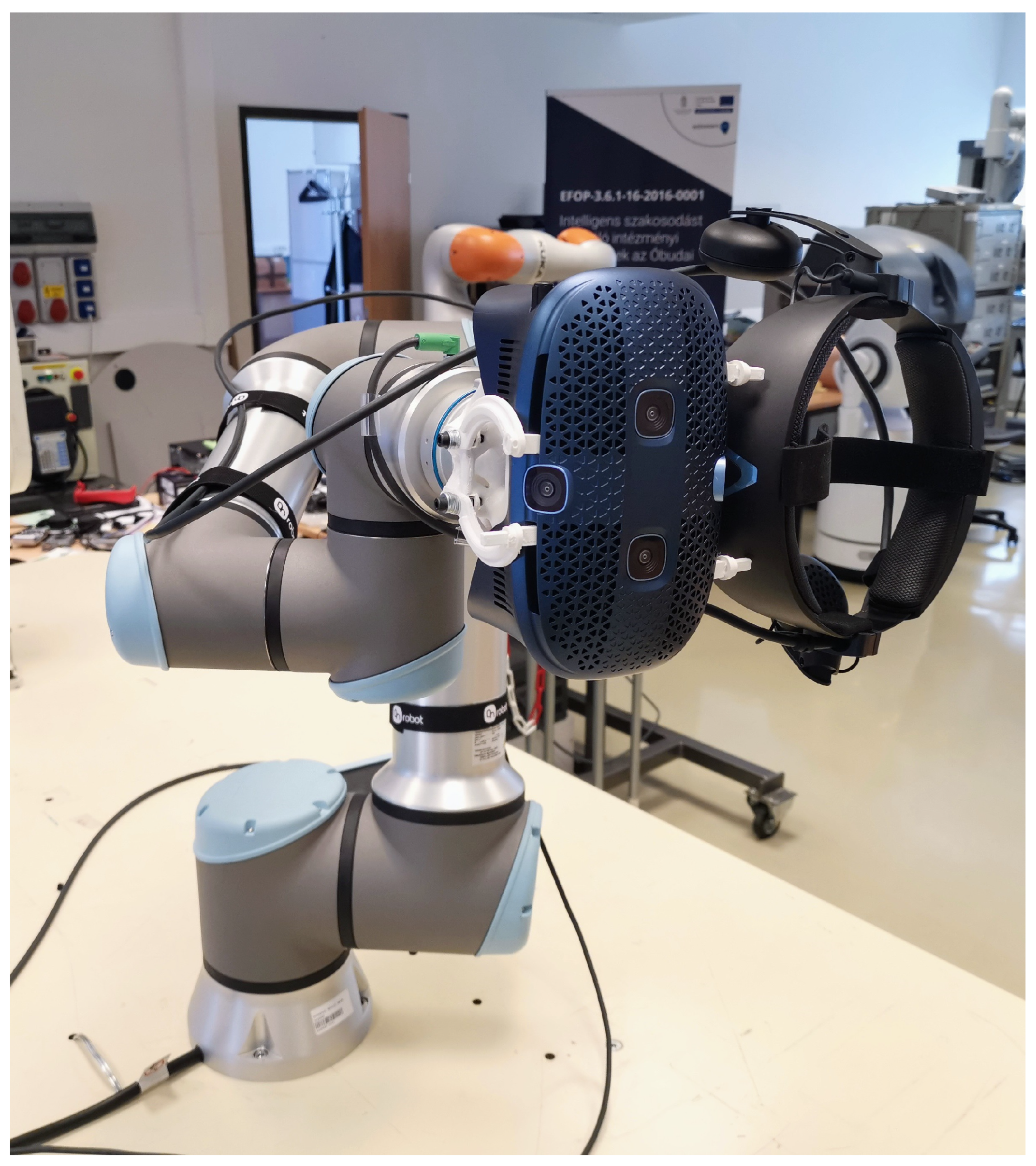
Figure 2.
Robot manipulator with an orientation sensor (illustrated as a box on the flange) with the frames and measured quantities considered throughout the paper.
Figure 2.
Robot manipulator with an orientation sensor (illustrated as a box on the flange) with the frames and measured quantities considered throughout the paper.
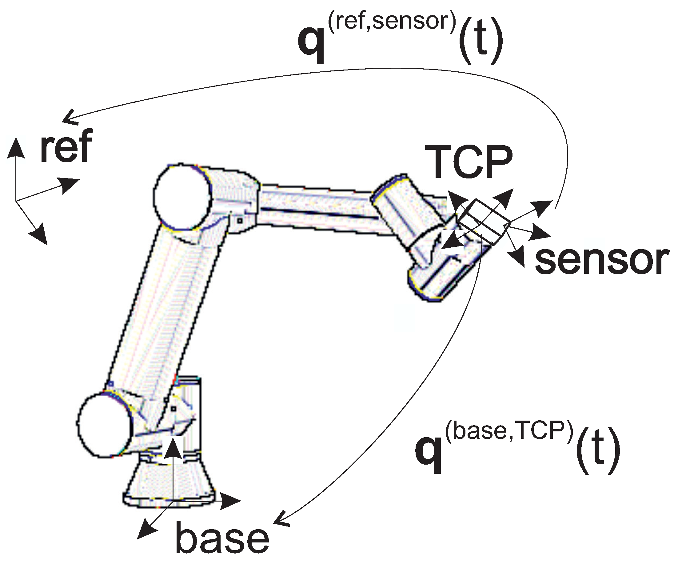
Figure 3.
The sensor (illustrated by a box) in three A, B, C poses, the axes of rotation and the resulted frame i with base vectors , and .
Figure 3.
The sensor (illustrated by a box) in three A, B, C poses, the axes of rotation and the resulted frame i with base vectors , and .
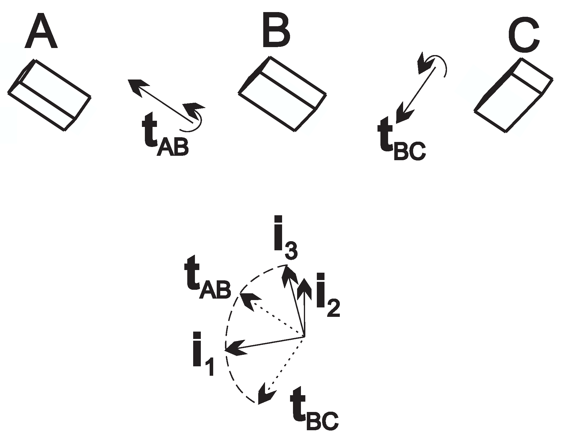
Figure 4.
3D TCP path of the measurement. Red and blue segments show direction x and z respectively.
Figure 4.
3D TCP path of the measurement. Red and blue segments show direction x and z respectively.
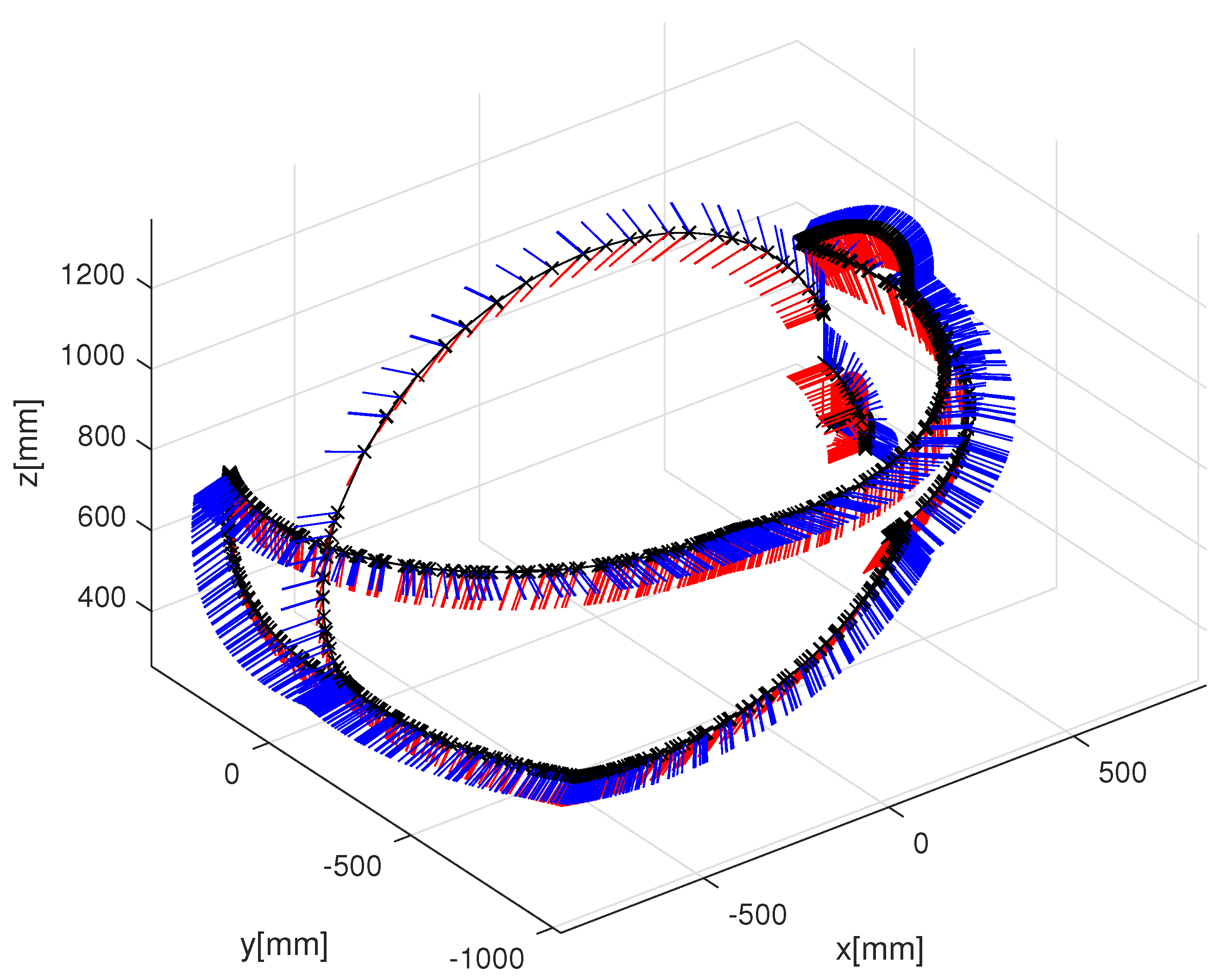
Figure 5.
The computed error of the IMU orientation according to the orientation computed from the robot model (blue), rotation angle between the measured TCP orientations (red). Larger errors occur only during transient motion.
Figure 5.
The computed error of the IMU orientation according to the orientation computed from the robot model (blue), rotation angle between the measured TCP orientations (red). Larger errors occur only during transient motion.
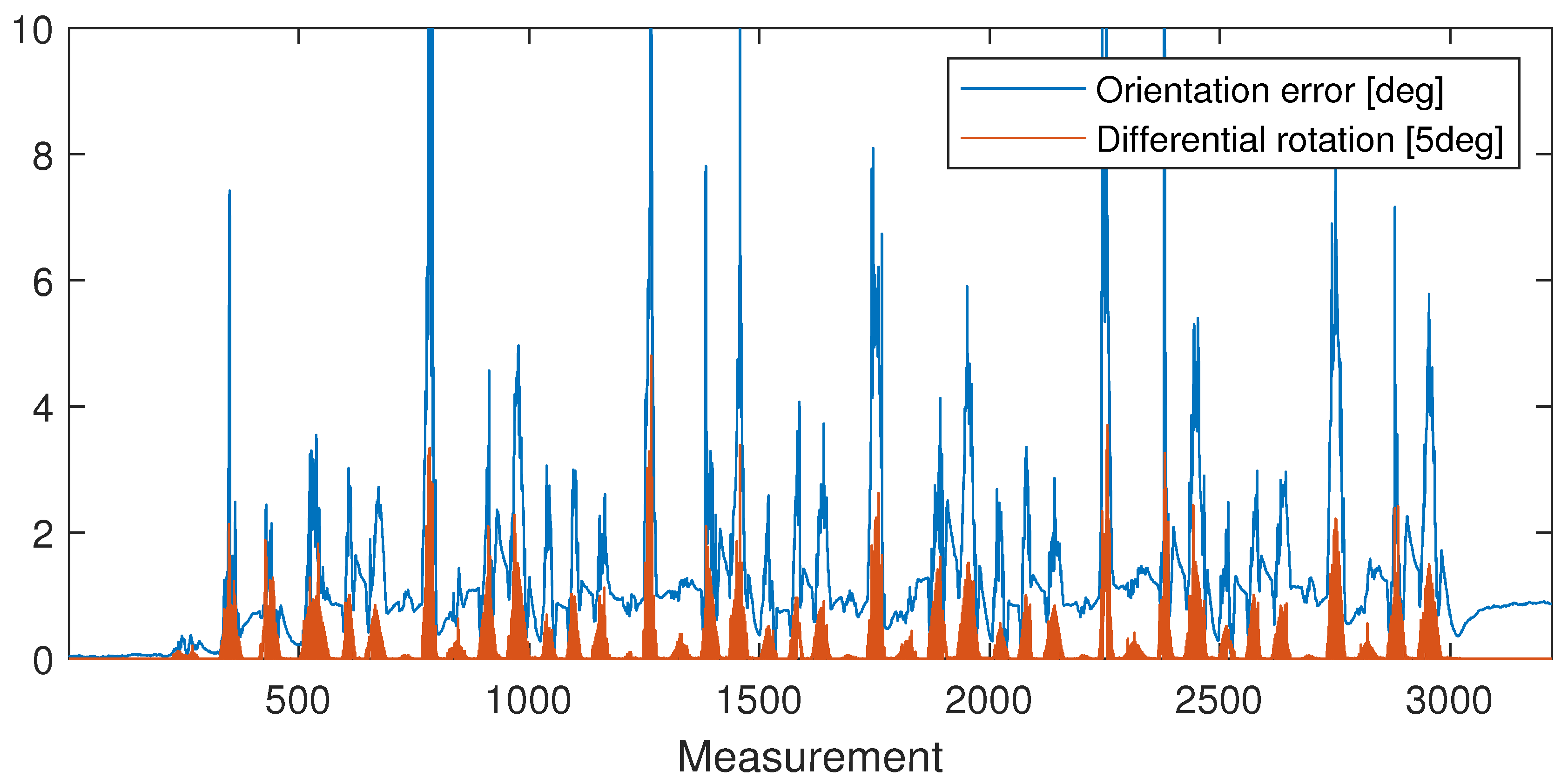
Figure 6.
Histogram of the computed error of the IMU orientation according to the orientation computed from the robot model.
Figure 6.
Histogram of the computed error of the IMU orientation according to the orientation computed from the robot model.
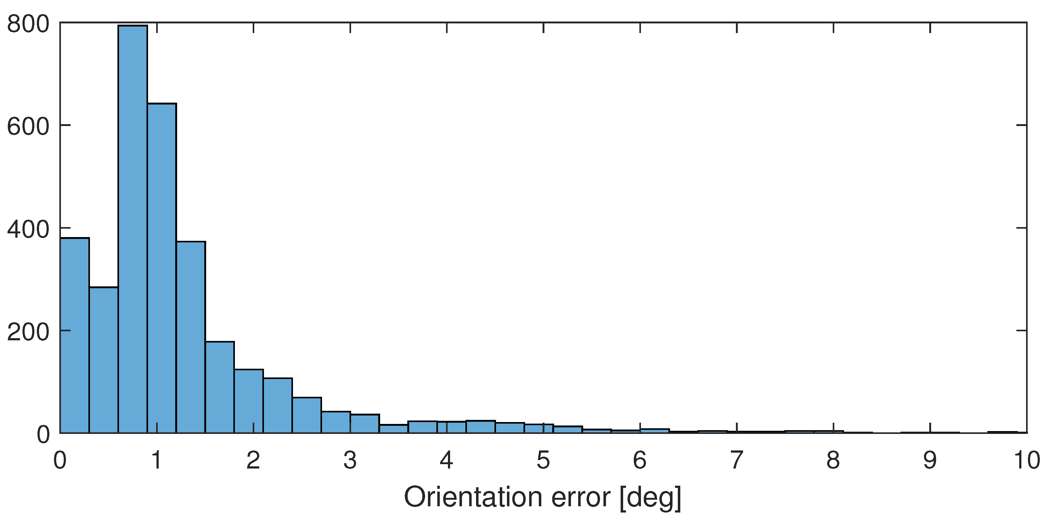
Figure 7.
The computed error of the HTC VIVE orientation according to the orientation computed from the robot model (blue), rotation angle between the measured TCP orientations (red). Larger errors occur only during transient motion.
Figure 7.
The computed error of the HTC VIVE orientation according to the orientation computed from the robot model (blue), rotation angle between the measured TCP orientations (red). Larger errors occur only during transient motion.
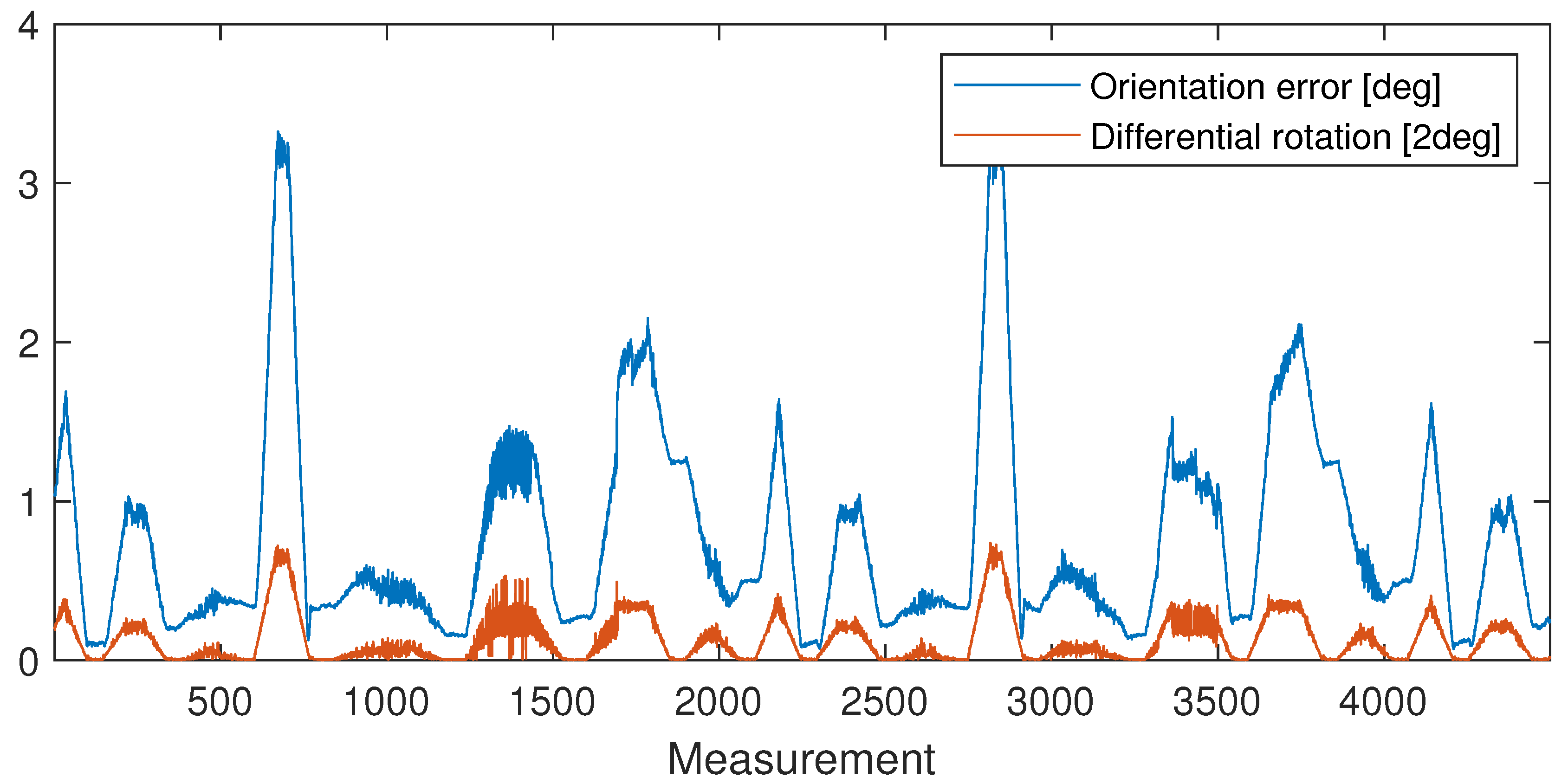
Figure 8.
Histogram of the computed error of the HTC VIVE orientation with respect to the orientation computed from the robot model.
Figure 8.
Histogram of the computed error of the HTC VIVE orientation with respect to the orientation computed from the robot model.
Disclaimer/Publisher’s Note: The statements, opinions and data contained in all publications are solely those of the individual author(s) and contributor(s) and not of MDPI and/or the editor(s). MDPI and/or the editor(s) disclaim responsibility for any injury to people or property resulting from any ideas, methods, instructions or products referred to in the content. |
© 2024 by the authors. Licensee MDPI, Basel, Switzerland. This article is an open access article distributed under the terms and conditions of the Creative Commons Attribution (CC BY) license (http://creativecommons.org/licenses/by/4.0/).
Copyright: This open access article is published under a Creative Commons CC BY 4.0 license, which permit the free download, distribution, and reuse, provided that the author and preprint are cited in any reuse.


