
Submitted:
26 September 2024
Posted:
27 September 2024
You are already at the latest version
Abstract
In the DC distribution networks, DC bus voltage is maintained by the grid-connected converter, the controllability and reliability of the grid-connected converter significantly affects the bus voltage characteristic. To address the problem of limited stability and frequent oscillations, this paper proposes a state feedback control method for the AC/DC converter. Conventional AC/DC converter adopts the voltage-current double-closed-loop control structure with the proportional integral (PI) controllers, which is the equivalent of the typical type II control system, but the typical type II control system cannot fully settle the stability and immunity problems. In contrast, the state feedback control strategy not only achieves the control objectives of the traditional double-closed-loop control, but also reduce the AC/DC converter system model to a typical I-type system, which improves the stability, thus enhances the oscillation suppression capability of the bus voltage. By selecting multiple state variables and designing the converter pole configuration range, the proposed single-loop state feedback control method manages to optimize both the dynamic and steady-state performances of the grid-connected AC/DC converter. Finally, the effectiveness of the proposed single-loop state feedback control strategy has been verified by both the simulation and experiment results.
Keywords:
AC/DC converter
; DC distribution network
; model order reduction
; state feedback control
; stability analysis
1. Introduction
Given the escalating severity of global environmental issues, the transition from traditional fossil fuels to new forms of energy has been accelerated, leading to substantial development in the field of renewable energy generation. Due to the extensive distribution of energy resources, distributed generation is a critical component of renewable power generation. DC grid technology for new energy power generation is a key technological solution [1,2,3], and the typical structure of a renewable power based DC distribution grid is shown in Figure 1.
Through effective coordinated control and energy management in DC grid systems, the uncertainty brought by renewable energy generation and random loads can be mitigated, allowing for greater absorption of power generated by renewable energy units [4,5,6,7]. Voltage Source Converters (VSC), with their advantage of bidirectional power flow, have been widely applied in the renewable energy network building [8]. When power is transferred from the AC side to the DC side, the VSC operates in rectification mode. When converters operate in DC network distribution, the system has low inertia, and the small-signal stability and controllability of the multi-converter system become bottlenecks constraining for its development [9]. In the renewable energy based DC distribution network, AC/DC converter, as the power conversion link between the DC bus and the AC grid, plays a critical role in maintaining the stable operation of the DC bus, and their stability and controllability are the key factors for the stable operation of the whole network system.
Traditional control strategies for AC/DC converter employ a voltage-current double-closed-loop control structure, using PI regulators. This control approach does not require high model accuracy and becomes the prevailing control strategy currently. However, the PI-controlled double-closed-loop structure only requires the feedback on partial variables, and the double -loop architecture imposes specific bandwidth requirements for both the inner and outer loops. Additionally, the inner and outer loop regulators must be matched in design, which limits their optimal controllable range. Regarding the damping characteristics of double -loop control systems, during design stage, the PI parameters are typically selected to be slightly under-damped to accommodate the response speed. For disturbance rejection, the double-loop control of converters operating as a typical Type II system, it cannot fully reconcile the trade-off between stability performance and disturbance rejection [10]. Moreover, systems controller tuned as typical Type II system exhibits significant phase lag in open loop transfer function at low frequencies, leading to relatively limited system stability.
The model order reduction of the converter from a typical Type II to Type I can improve its stability characteristics while retaining its disturbance rejection capabilities. For converter model order reduction control strategies, reference [11] targets MMC circuits by replacing the PI regulator in the outer loop with a proportional controller, achieving model order reduction and enhancing control performance. However, this reduced-order control is only effective during the startup phase of the converter, and a steady-state error occurs when using a proportional controller during grid-connected operation. The introduction PI controllers increases the order of converter equivalent model, leading to reduced damping and redundancy performance. For the inherent nonlinearity in converter models, nonlinear control methods can be employed, although these algorithms involve higher computational complexity [12,13,14]. Using state feedback linearization can achieve the decoupling control, power factor correction, and desired dynamic performance [15,16], but this method suffers from complex decoupling matrices and high computational burdens, limiting the practical application. Reference [17] proposes a quasi-linearization method to obtain an exact linear model and designs a state feedback controller for PWM converters, where a pseudoinverse matrix is utilized, and it can simplify the implementation of the controller. However, the design still employs a dual-loop structure with a PI controller in the outer loop, without achieving model order reduction and damping optimization. Reference [18] proposes an voltage control method for single-phase voltage source converters, with the combining integral state feedback through repetitive control. The integral control manages to improve the steady-state accuracy of state feedback control, and repetitive control enhances the inverter's capability to handle nonlinear loads. However, this controller design focuses solely on the AC-side filter, without incorporating state variables from the DC side, leading to incomplete system feedback. Reference [19] introduces an integrated control system for three-phase inverters combining integral control with state feedback and applies Linear Quadratic Regulator (LQR) theory to solve parameter tuning issues. LQR optimal control can effectively design state feedback parameters, but the basis for defining the weighting matrix remains unclear, thus limiting the control performance. Additionally, state feedback control can implement active damping effect for LCL filters [20,21,22,23], suppressing resonance peaks. Reference [24] proposes an improved inner-loop control strategy for bidirectional AC/DC converter to suppress voltage fluctuations, enabling rapid tracking of equivalent disturbance currents without additional voltage/current sensors, thereby enhancing the anti-interference capability of the converter networked system. Using disturbance feedforward, external disturbance power is fed forward to suppress DC bus voltage fluctuations, but this requires additional voltage/current sensors in the control loop [25,26]. Implementing state feedback control for inverters, applying state feedback methods to LCL filters in grid-connected converters can improve damping characteristics, but research on implementing model order reduction and stability improvement for converters using state feedback methods remains relatively scarce.
To achieve model order reduction and stability enhancement of AC/DC converter, this paper employs a single-loop control state feedback strategy to enable a larger scope pole placement, enhance the damping characteristics and model redundancy of the AC/DC converter system. Meantime, it’s also capable to reduce the number of characteristic roots at the origin point of complex plane, thereby realizing model order reduction. By selecting extra state variables, specifically the DC-side capacitor energy mapping variables, a coupled linearized model of the DC-AC sides of the grid-connected converter is established, and a single-loop state feedback controller is designed. Leveraging the advantages of state feedback, this approach achieves better pole placement and model order reduction, improving the control characteristics of the DC bus voltage of the grid-connected converter. Compared with the traditional PI control, the single-loop state feedback control achieves the control objectives of the traditional PI controller based control solution, with zero steady-state error in voltage output and dynamic regulated output current. The reduced-order to typical Type I system under single-loop state feedback control shows significant improvements in dynamic and redundancy. Finally, the applicability and effectiveness of the single-loop state feedback control strategy are verified through MATLAB/Simulink simulations and experiments on a DC network platform.
2. Mathematical Model of AC/DC Converter
In the grid-connected renewable energy power generation, the effective control of AC/DC converter plays a crucial role . The topology of the AC/DC converter is shown in Figure 2. As shown in Figure 2, ea, eb, ec represent the AC grid voltage; L is the inductor filter; r is the filter parasitic resistance; C is the DC side filter capacitance; uaN, ubN, ucN are the voltages at the converter terminals relative to the neutral point; ia, ib, ic are the inductor currents towards the grid side; iL is the current in the DC side.
The equations on inductor can be expressed as
The state equation at the DC side capacitor is
When neglecting power loss, the energy variations on DC-side capacitor is defined as
where, ΔWC is the exchanged energy stored in the capacitor, Wac is the energy flowing into the AC side, Wdc is the exchanged energy from the DC side.
The energies can be expressed as
The power relationship between the AC and DC sides is defined as
From Equations (3), (4), and (5), Equation (6) can be calculated as
Under steady-state, eq=0, the linear mathematical model of the grid-connected converter can be expressed as
The state variables are id, iq, udc2; the input variables are ud、 uq; the output variables are udc2, iq.
The state-space representation of equation (7) can be expressed as
where, the system matrix As, input matrix Bs, disturbance input matrix Es, state variable xs, input vector us, and disturbance input vector ds are defined as follow
According to (7), the block diagram of the grid-connected converter can be obtained as Figure 3. The state variable udc2 can get rid of the product term between voltage and current, thereby establishing a linear model for the grid-connected converter.
3. Analysis of Double-Closed-Loop PI Control for AC/DC Converter
The block diagram of the double-loop PI control for the AC/DC converter are shown in Figure 4 and Figure 5. The inner current loop follows the command from the outer voltage loop to control the current, equivalent to a second-order system. The system's reference tracking and disturbance rejection capabilities cannot be fully optimized simultaneously. Additionally, the transient performance of a typical type II system exhibit significant resonant behavior, which can lead to pronounced resonance issues if not effectively damped [27].
From Figure 5, the open-loop transfer function of the double-closed-loop control can be expressed as
where, Kvp and Kvi are the proportional and integral coefficients of the outer-loop PI controller respectively, and Dde is the steady-state value of the switching duty ratio on d-axis. The bandwidth of the current loop is often designed to be 1/20 of the switching frequency, and the current loop can be simplified as follows
where, fs is the switching frequency, and Tev is the equivalent time constant of the current loop.
The system transfer function under double-loop PI control is expressed as
where, Tv are the integral time constant of the outer loop, Tev is the equivalent time constant for the inner current control loop. The closed-loop transfer function is expressed as
where, ; ;.
From (11), it can be concluded that the converter with double-loop PI control is a typical type II system. From (12), it can be seen that only a2 and a3 in the characteristic equation can be adjusted, thus the location of the characteristic roots cannot be completely designed. The poles can only be adjusted along specific trajectories, making it impossible to configure them exactly and arbitrarily. The root locus is shown in Figure 6, where red represents the poles and green represents the zeros; Figure 6 shows the root locus when changing the parameters of the inner and outer loops. As shown in the figure, changing the parameters of the inner and outer loop controllers causes the characteristic roots to migrate only along the red trajectory, which limits the controllability and stability of the AC/DC converter.
4. Single-loop State Feedback Control
State feedback control feedback system state variables through corresponding coefficients, as shown in Figure 7. The systematic matrix changes from A to (A+BK), leading to a desired control characteristics. This paper proposes a single-loop state feedback control method to improve the stability and controllability of the AC/DC converter.
4.1. Single- Loop State Feedback Architecture
The proposed single -loop state feedback control structure is shown as Figure 8. Compared with traditional PI control, the proposed control introduces three state variables id, udc2, and mdc on the d-axis and two state variables iq and miq on the q-axis. The introduction of mdc and miq is aimed at achieving zero steady-state error. The converter system has improved controllability with the pole placement over a wider range.
4.2. Design of Single-loop State Feedback Controller for AC/DC Converter
To eliminate the steady-state error, the voltage control loop is designed as follow
where, mdc is the error integral state variable, whose value reflects the relative size of the capacitor energy; udc2* is the specified value of the square of the capacitor voltage.
Therefore, the state-space expression for the d-axis after decoupling and introducing integration can be expressed as
where, usd and yd are the reference input and output. The remaining d-axis system matrix Ad, input matrix Bd, state variable xd, reference input matrix Bd* and output matrix Cd are defined as follow
The state-space expression for the q-axis can be expressed as
where, usq and yq are the reference input and output on the q-axis respectively. The remaining q-axis system matrix Aq, input matrix Bq, state variable xq and reference input matrix Bq* and output matrix Cq are defined as follow
The voltage control characteristics of the AC/DC converter are determined by the feedback coefficients of three state variables. Traditional PI control uses an outer voltage loop and an inner current loop, and during design, these loops are typically treated as two separated systems. When designing the inner loop, only the inductor current is fed back, while designing the outer loop only involves the feedback of DC voltage. In contrast, state feedback control designs the system as incorporating feedback of both the inductor current and the capacitor voltage to achieve better pole placement with improved system performance.
Due to the absence of a traditional inner current loop, single-loop state feedback control cannot directly limit the d-axis current. However, indirect current limiting can be designed by constraining the error in the square of the voltage, thereby achieving the purpose of current limitation, as shown in Figure 9.
Assuming Pdc=0, the transfer function from Δmax to id can be expressed as
id varies with Δmax, and the relationship between Δmax and id is
when Pdc≠0, the limiting is dynamic limiting, and the formula can be described as
The q-axis current limit iqmax is determined based on the d-axis current limit idmax. According to the power circle relationship, the q-axis current limit is
where, iN is the rated current of the converter design.
5. Pole Placement for Single-loop State Feedback Control of AC/DC Converter
5.1. Pole Placement Region
Pole placement typically employs the dominant pole placement method, simplifying the system to a second-order system for pole placement.
Assuming the desired time-domain performance indices be the settling time ts* and the percent overshoot Mp*; the frequency-domain performance indices be the lower bandwidth limit ωbd*, and the resonance peak Mr*; and the disturbance rejection performance index be the upper bandwidth limit ωbu*. The system poles are designed using the dominant pole placement method, and the system poles are defined as
For a second-order system, the settling time and percent overshoot are expressed as
The damping ratio of the system can be determined through the overshoot criterion, which in turn determines the damping angle. The real part of the poles can be determined through the settling time. The range of the poles can be determined using time-domain and frequency-domain criteria as follow
5.2. Three-Pole Configuration for AC/DC Converter
The grid-connected converter system can be considered as a three-pole system. The three-pole configuration modes are shown in Figure 10 and can be divided into three types. Mode (a) features two poles close to the imaginary axis as the dominant poles, with another pole located at a distance four to six times further away. Mode (b) consists of a pair of conjugate poles and a pole on the real axis, which can achieve no overshoot, equivalent to a second-order system in series with a first-order system. Mode (c) features all three poles on the real axis, equivalent to three first-order systems in series, resulting in maximum system damping and better disturbance rejection.
6. Comparison between Single-loop State Feedback Control and Double- Loop PI Control
The state feedback control law for the single-loop control on the d-q axes are expressed as
From (14), (15), and (23), (24) can be obtained as
where, ,,.
The open-loop transfer functions under single-loop state feedback control are expressed as
The coefficients of the characteristic equation change with the proportional parameters kd1, kd2 and kd3 allowing for more flexible pole placement to achieve the desired system performance. From the open-loop transfer function, it can be seen that the system is a typical Type I system with enhanced damping characteristics and stability.
The selected parameters for the AC/DC converter are: transmitted power 20 kW, DC bus voltage 800 V, grid phase voltage 220 V, filter inductance 5 mH, equivalent parasitic resistance 0.1 Ω, DC-side capacitance 3000 μF, resistive load 5 kW, constant power load 15 kW, and switching frequency 10 kHz. The time-domain performance criteria are ts<0.05 s, Mp<5%, and the upper bandwidth limit is set to 30 Hz. According to the time-domain criteria, the pole placement region can be determined using Equation(20), as shown in Figure 11. Three poles are chosen as -313, -312, and -311, resulting in a system with high damping that can achieve no overshoot. The response curve of the double-closed-loop PI control meets the 5% overshoot criterion and represents the fastest response curve, as shown in Figure 13. The relevant parameters are provided in Table 1.
6.1. Bode Plot Characteristic Analysis
The Bode plots for the traditional double-loop PI control and the single-loop state feedback control proposed in this paper are shown in Figure 12. Under double-loop PI control, the converter system is a typical Type II system, whereas the single-loop state feedback control is equivalent to a typical Type I system, achieving model order reduction. In the low-frequency range, the PI control model exhibits a -40 dB/dec roll-off, indicating a higher gain and thus smaller steady-state error. The phase lag is smaller for the single-loop state feedback control, indicating better stability. The mid-bandwidth of the state feedback is wider compared to PI control, indicating better disturbance rejection, and its cutoff frequency is higher, indicating a broader control bandwidth, effectively widening the bandwidth of the double-closed-loop PI control. In the high-frequency range, the state feedback exhibits a -60 dB/dec roll-off, indicating stronger suppression of high-frequency interference.
6.2. Dynamic Performance Comparison
By changing the PI parameters, it can be observed from Figure 13 that the orange line represents the fastest response curve that meets the 5% overshoot criterion, indicating that the PI parameters are optimal at this point. As the proportional coefficient increases, the overshoot decreases, but there is still slight overshoot. With an increase in the integral coefficient, the settling time shortens, but the overshoot increases. The red curve represents the response curve of the state feedback control, showing rapid response with no overshoot.
6.3. Disturbance Rejection Analysis
Based on load power disturbances, compare the voltage recovery capabilities of the two control methods. Combining Equations (9) and (21), the disturbance transfer function for the state feedback control can be obtained as
Linearizing Equation (26), the relationship between ΔPdc and ΔUdc can be expressed as
The transfer function from changes in transmitted power to the DC bus voltage can be obtained as
where, Udce is the DC bus voltage at steady state.
The transfer function from transmitted power to the DC bus voltage under PI control can be expressed as
where, kip and kiI are current loop coefficients, kvp and kvI are voltage loop coefficients.
Figure 14 shows the Bode plot of the disturbance transfer function for traditional PI control and the state feedback control used in this paper. The red curve in the figure represents the single-loop state feedback control, and the orange curve represents the traditional PI control. By comparison, it can be seen that the single-loop state feedback control has a lower gain, indicating stronger disturbance rejection capability, and a smaller phase lag in the phase angle characteristics.
The designed single-loop state feedback controlled converter system is a typical Type I system, exhibiting a -20 dB/dec roll-off in the low-frequency range and a -60 dB/dec roll-off in the high-frequency range, providing better disturbance rejection. In contrast, the PI control has a double-loop structure; when the DC bus voltage changes, the outer loop detects the change first, followed by the inner loop, forming the control law ud, with a dynamic response process that is slower than that of the state feedback control.
5.4. Redundancy Characteristic Analysis
The uncertainty and migration of the DC-side voltage Udce affect the converter operation, thereby impacting its stable operation and potentially leading to instability.
Figure 15 shows the pole distribution for the DC bus voltage ranging from 600 to 1000 V. In the single-loop state feedback control, the static operating point voltage Udce is not utilized, so changes in the DC bus voltage do not significantly affect the performance of the state feedback system. In contrast, in the double-closed-loop PI control, the static operating point voltage Udce directly affects the gain of the modulation stage. As shown in the figure, as the voltage increases, the system poles move to the right, slowing down the response characteristics. From an energy perspective, because a higher capacitor voltage requires more energy for voltage regulation, this slows down the voltage response speed.
7. Simulation and Experimental Verification
7.1. Simulation Verification
The simulation parameters are set identically to the theoretical analysis parameters, and the simulation model is built using MATLAB/Simulink. The simulation validates the dynamic performance, disturbance rejection, and the impact of parameter uncertainties.
Figure 16 shows the step response comparison. At 0.5 seconds, the DC-side voltage of the converter steps from 800 V to 1000 V. As can be seen from the figure, the single-loop state feedback control response curve is clearly superior to that of the double-closed-loop PI control, corresponding to the effect of model order reduction. For traditional PI control, an increase in the proportional coefficient improves the response characteristics; however, an increase in the integral coefficient enhances the effect of raising the model order, leading to increased overshoot. Overall, the single-loop state feedback control achieves model order reduction and zero steady-state error output.
Figure 17 shows the simulation results for disturbance rejection characteristics. At 0.4 seconds, a 15 kW constant power load is connected, causing an instantaneous drop in the DC bus voltage. At 1.2 seconds, the constant power load undergoes a step change, transitioning from a 15 kW load to generating 15 kW of power, simulating a sudden change from power absorption to power output by the energy storage unit. At 1.2 seconds, the DC bus voltage rises, and there is a jump in the power output to the grid by the converter. In the presence of the same power disturbance, the single-loop state feedback control exhibits smaller DC bus voltage fluctuations and faster recovery times, indicating stronger resistance to transmission power disturbances.
Figure 18 shows the step response and power disturbance characteristics after the DC bus voltage stepping under varying outer-loop integral values. As the integral coefficient increases, the system's disturbance rejection capability improves, but the overshoot also increases. The red waveform in the figure represents the single-loop state feedback control, which achieves good levels of dynamic performance and disturbance rejection.
Figure 19 shows the DC bus voltage response curves under single-loop state feedback control with varying parameters. Figure 19(a) illustrates the response curves when the DC-side capacitance changes by ±10%. When the capacitance parameter changes, it causes a certain degree of slowing in the response characteristics, but the overall response time remains largely unchanged. This is because when the capacitance increases or decreases, some poles move to the right of the configured poles, slowing the initial response stage, but they do not move outside the configured range, thus the settling time remains unchanged. Figure 19(b) illustrates the response curves when the AC-side filter inductance changes by ±10%. The response characteristics when the inductance changes are similar to those when the capacitance changes. When the inductance increases, the initial and final stages slow down, while the middle stage changes faster, and the overall response characteristics still meet the design requirements. When the inductance increases, the pole damping decreases, with two poles moving to the upper left and lower left, and one pole moving to the right, with the left poles speeding up the middle stage response and the right pole slowing the initial stage response. Figure 19(c) illustrates the response curves when the grid voltage changes by ±30%. As shown in the figure, changes in grid voltage have a minimal impact on system performance and the response curves are essentially the same as those under normal parameters.
7.2. Experimental Verification
To verify the effectiveness of the single-loop state feedback control strategy, an experimental platform for a DC network building converter system was set up. The platform uses an industrial open-source inverter for the AC/DC converter and a dSPACE Micro-LabBox real-time controller for the control loop. The DC network building converter includes a bus power simulation converter and a DC bus converter. Comparative experiments were conducted in terms of dynamic performance and disturbance rejection. The experimental hardware is shown in Figure 20, the experimental system is shown in Figure 21, and the experimental parameters are listed in Table 2.
Figure 22 shows the experimental comparison between single-loop state feedback control and double- loop PI control, where the DC bus voltage steps from 350 V to 450 V. As can be seen from the figure, the DC bus voltage under single- loop state feedback control responds faster and without overshoot, whereas the double-closed-loop PI control exhibits overshoot and longer settling time. The dynamic characteristics under both strategies are consistent with the transient characteristics of typical Type I and Type II systems, verifying the role of single-loop state feedback in reducing steady-state error and model order reduction.
Figure 23 shows the step response waveforms of the AC/DC converter under variations in the PI regulator parameters. Increasing the proportional coefficient leads to increased high-frequency ripple in the DC bus voltage and poorer steady-state characteristics. Decreasing the proportional coefficient or increasing the integral coefficient results in greater overshoot and poorer dynamic characteristics. Decreasing the integral coefficient reduces the overshoot but increases the settling time. Therefore, the traditional double-closed-loop PI control strategy for voltage and current exhibits significant limitations.
Figure 24 shows the voltage and power waveforms of the DC/AC grid-tied converter. During the transient process, the voltage outer loop regulator saturates, resulting in the voltage rising at its maximum slope during the dynamic response, causing the regulator to lose its control function. However, under single-loop state feedback control, the DC bus voltage and power do not saturate. It can be seen from the figure that, under single-loop state feedback control, the transient power fluctuation of the grid-tied converter is slightly larger, but the DC-side voltage control is more stable. The power fluctuations provide rapid compensation for the variations in the DC-side voltage.
Figure 25 and Figure 26 show the DC bus voltage waveforms for the AC/DC converter under forward and reverse power transmission conditions, respectively. The forward power condition involves the power consumption of the DC bus power simulation converter stepping from 200 W to 1000 W, causing the DC bus voltage to drop. The reverse power condition involves the power generation of the power simulation converter stepping from 200 W to 1000 W, causing the DC bus voltage to rise. As can be seen from the figures, the DC bus voltage recovery time is shorter under single-loop state feedback control. This verifies that the disturbance rejection capability of the single-loop state feedback control is stronger than that of the traditional double-closed-loop PI control.
Figure 27 shows the step response of voltage under changes in the inductance parameter. As shown in the figure, when the inductance is reduced by 35%, the performance of the single- loop state feedback control still ensures control characteristics, although the reduction in inductance value leads to an increase in current harmonic content. Figure 28 shows the step response curves when the grid voltage changes by ±30%. It can be seen that changes in grid voltage parameters have a minimal impact on the single-loop state feedback control.
8. Conclusions
This paper proposes a model order reduction single-loop state feedback control for DC distribution network AC/DC converter, reducing the traditional double-closed-loop PI control from the typical Type II system to typical Type I system, effectively enhancing the damping and disturbance rejection characteristics of the DC-side voltage control. Comparative analyses were conducted with PI control in terms of stability, dynamic characteristics, disturbance rejection, and parameter variations, leading to the following conclusions:
- In terms of stability, the single-loop state feedback control can achieve the same control objectives as PI control, with less phase lag at low frequencies, resulting in better stability;
- In terms of dynamic characteristics, the single-loop state feedback control exhibits significantly better controllability compared to traditional double-closed-loop PI control, equivalent to a typical Type I system. The single-loop state feedback allows for more flexible pole placement within the system constraints, thereby achieving better dynamic performance;
- In terms of disturbance rejection, the single-loop state feedback exhibits stronger disturbance rejection characteristics. Its equivalent transfer function has a high frequency roll-off of -60 dB/dec.
Author Contributions
Conceptualization, T.Y. and L.Y.; methodology, B.W and T.Y.; formal analysis, C.X.; data curation, P.Q.; writing—original draft preparation, L.Y..; writing—review and editing, T.Y.; visualization, X.X.; project administration, C.X. All authors have read and agreed to the published version of the manuscript.
Funding
This work was supported by the Project Supported by Science and Technology Project of State Grid Zhejiang Electric Power Co, Ltd (5211DS230005); and the Natural Science Foundation of Hebei Province (E2022502032).
Data Availability Statement
The data that support the findings of this study are available from the corresponding author upon reasonable request.
Conflicts of Interest
The authors declare that they have no conflicts of interest.
Appendix A
| Parameters | Definitions |
| ea, eb, ec | the AC grid voltage |
| L | the inductor filter |
| r | the filter parasitic resistance |
| C | the DC side filter capacitance |
| uaN, ubN, ucN | the voltages at the converter terminals relative to the neutral point |
| ia, ib, ic | the inductor currents towards the grid side |
| iL | the current in the DC side. |
| ΔWC | the exchanged energy stored in the capacitor |
| Wac | the energy flowing into the AC side |
| Wdc | the exchanged energy from the DC side |
| As | the system matrix |
| Bs | input matrix |
| Es | disturbance input matrix |
| xs | state variable |
| us | input vector |
| ds | disturbance input vector |
| Kvp | the proportional coefficients of the outer-loop PI control |
| Kvi | the integral coefficients of the outer-loop PI control |
| KiP | the proportional coefficients of the inner-loop PI control |
| KiI | the integral coefficients of the inner-loop PI control |
| fs | the switching frequency of the grid-connected converter modulation |
| Tv | the integral time constant of the outer loop |
| Tev | the equivalent time constant of the current inner loop |
| mdc | the error integral state variable |
| udc2* | the specified value of the square of the capacitor voltage |
| usd,q | the reference input in d, q-axis |
| yd,q | the reference output in d, q-axis |
| Ad,q | the system matrix in d, q-axis |
| Bd,q | the input matrix in d, q-axis |
| xd,q | the state variable in d, q-axis |
| Bd,q* | the reference input matrix in d, q-axis |
| Cd,q | the output matrix in d, q-axis |
| imax | current limit |
| id,qmax | the current limit in d, q-axis |
| iN | the rated current of the converter design |
| ts* | the desired settling time |
| Mp* | the desired percent overshoot |
| Mr* | the desired |
| ωbu,d* | the desired the lower, upper bandwidth limit |
| ts | the settling time |
| Mp | percent overshoot |
| ΔPdc | the variation in DC-side power |
| ΔUdc | the variation in DC-side voltage |
| Udce | the DC bus voltage at steady state |
References
- Muhtadi, A.; Pandit, D.; Nguyen, N.; Mitra, J. Distributed Energy Resources Based Microgrid: Review of Architecture, Control, and Reliability. IEEE Trans. on Ind. Applicat. 2021, 57, 2223–2235. [Google Scholar] [CrossRef]
- Blaabjerg, F.; Teodorescu, R.; Liserre, M.; Timbus, A.V. Overview of Control and Grid Synchronization for Distributed Power Generation Systems. IEEE TRANSACTIONS ON INDUSTRIAL ELECTRONICS 2006, 53. [Google Scholar] [CrossRef]
- Liang, X.; Andalib -Bin- Karim, C. Harmonics and Mitigation Techniques Through Advanced Control in Grid-Connected Renewable Energy Sources: A Review. IEEE Trans. on Ind. Applicat. 2018, 54, 3100–3111. [Google Scholar] [CrossRef]
- Nejabatkhah, F. Overview of Power Management Strategies of Hybrid AC/DC Microgrid. IEEE TRANSACTIONS ON POWER ELECTRONICS 2015, 30. [Google Scholar] [CrossRef]
- Dragicevic, T.; Lu, X.; Vasquez, J.; Guerrero, J. DC Microgrids–Part I: A Review of Control Strategies and Stabilization Techniques. IEEE Trans. Power Electron. 2015, 1–1. [Google Scholar] [CrossRef]
- Dragicevic, T.; Lu, X.; Vasquez, J.C.; Guerrero, J.M. DC Microgrids—Part II: A Review of Power Architectures, Applications, and Standardization Issues. IEEE Trans. Power Electron. 2016, 31, 3528–3549. [Google Scholar] [CrossRef]
- Xuan, Z.; Gao, X.; Li, K.; Wang, F.; Ge, X.; Hou, Y. PV-Load Decoupling Based Demand Response Baseline Load Estimation Approach for Residential Customer With Distributed PV System. IEEE Trans. on Ind. Applicat. 2020, 56, 6128–6137. [Google Scholar] [CrossRef]
- Faraji, R.; Ding, L.; Mazloum, N. Soft-Switched Single Inductor Single Stage Multiport Bidirectional Power Converter for Hybrid Energy Systems. IEEE TRANSACTIONS ON POWER ELECTRONICS 2021, 36. [Google Scholar] [CrossRef]
- Tu, H.; Yu, H.; Lukic, S. Impact of Virtual Inertia on DC Grid Stability With Constant Power Loads. IEEE TRANSACTIONS ON POWER ELECTRONICS 2023, 38. [Google Scholar] [CrossRef]
- Meng, J.; Wu, X.; Ye, T.; Yu, J.; Gu, L.; Zhang, Z.; Li, Y. Output Voltage Response Improvement and Ripple Reduction Control for Input-Parallel Output-Parallel High-Power DC Supply. IEEE TRANSACTIONS ON POWER ELECTRONICS 2023, 38. [Google Scholar] [CrossRef]
- Gong, S.; Li, X.; Han, J.; Sun, Y.; Xu, G.; Jiang, Y.; Huang, S. Sliding Mode Control-Based Decoupling Scheme for Quad-Active Bridge DC–DC Converter. IEEE JOURNAL OF EMERGING AND SELECTED TOPICS IN POWER ELECTRONICS 2022, 10. [Google Scholar] [CrossRef]
- Chen, J.-Y.; Yang, S.-C. Integration of Measurement Vector Insertion With Discontinuous PWM to Improve Saliency-Based Sensorless Drive Position Estimation. IEEE TRANSACTIONS ON POWER ELECTRONICS 2022, 37. [Google Scholar] [CrossRef]
- Yang, D.; Zhou, F.; Xiong, J. Research on Improved Three-Phase PWM converter Based on Sliding Mode Control. In Proceedings of the 2022 4th International Conference on Electrical Engineering and Control Technologies (CEECT); IEEE: Shanghai, China, December, 2022; pp. 1178–1182. [Google Scholar]
- Moeini, A.; Zhao, H.; Wang, S. A Current-Reference-Based Selective Harmonic Current Mitigation PWM Technique to Improve the Performance of Cascaded H-Bridge Multilevel Active converters. IEEE Trans. Ind. Electron. 2018, 65, 727–737. [Google Scholar] [CrossRef]
- Zhou, L.; She, J.; Zhang, X.-M.; Zhang, Z. Additive-State-Decomposition-Based Repetitive Control for a Class of Nonlinear Systems with Multiple Mismatched Disturbances. IEEE Trans. Ind. Electron. 2021, 68, 12565–12574. [Google Scholar] [CrossRef]
- Guo, Q.; Carrizosa, M.J.; Iovine, A.; Arzandé, A. Dynamic Feedback Linearization and Singular Perturbation for a Stabilizing Controller for DC/DC Boost Converters: Theory and Experimental Validation. IEEE Trans. Ind. Electron. 2024, 71, 9559–9568. [Google Scholar] [CrossRef]
- Quan, X.; Huang, A.Q. A Novel Dominant Dynamic Elimination Control for Voltage-Controlled Inverter. IEEE TRANSACTIONS ON INDUSTRIAL ELECTRONICS 2018, 65. [Google Scholar] [CrossRef]
- Kai Zhang; Yong Kang; Jian Xiong; Jian Chen Direct Repetitive Control of SPWM Inverter for UPS Purpose. IEEE Trans. Power Electron. 2003, 18, 784–792. [CrossRef]
- Jouybary, H.S.; Mpanda Mabwe, A.; Arab Khaburi, D.; El Hajjaji, A. An LMI-Based Linear Quadratic Regulator (LQR) Control for Modular Multilevel Converters (MMCs) Considering Parameters Uncertainty. IEEE Access 2024, 12, 111888–111898. [Google Scholar] [CrossRef]
- Zhang, H.; Ruan, X.; Lin, Z.; Guo, Y. Capacitor Voltage Full Feedback Scheme for LCL-Type Grid-Connected Inverter to Suppress Current Distortion Due to Grid Voltage Harmonics. IEEE TRANSACTIONS ON POWER ELECTRONICS 2021, 36. [Google Scholar] [CrossRef]
- He, Y.; Pan, D.; Xu, X.; Liu, F. Capacitor-Current Proportional-Integral Positive Feedback Active Damping for LCL-Type Grid-Connected Inverter to Achieve High Robustness Against Grid Impedance Variation. IEEE TRANSACTIONS ON POWER ELECTRONICS 2019, 34. [Google Scholar] [CrossRef]
- Li, S.; Lin, H. A Capacitor-Current-Feedback Positive Active Damping Control Strategy for LCL-Type Grid-Connected Inverter to Achieve High Robustness. IEEE TRANSACTIONS ON POWER ELECTRONICS 2022, 37. [Google Scholar] [CrossRef]
- Xue, M.; Zhang, Y.; Kang, Y.; Yi, Y.; Li, S.; Liu, F. Full Feedforward of Grid Voltage for Discrete State Feedback Controlled Grid-Connected Inverter With LCL Filter. IEEE Trans. Power Electron. 2012, 27, 4234–4247. [Google Scholar] [CrossRef]
- Zhang, Y. Grid-Voltage Sensorless Model Predictive Control of Three-Phase PWM converter Under Unbalanced and Distorted Grid Voltages. IEEE TRANSACTIONS ON POWER ELECTRONICS 2020, 35. [Google Scholar]
- Sato, A.; Noguchi, T. Voltage-Source PWM converter–Inverter Based on Direct Power Control and Its Operation Characteristics. IEEE Trans. Power Electron. 2011, 26, 1559–1567. [Google Scholar] [CrossRef]
- Zhang, Y. Direct Power Control of PWM converter With Feedforward Compensation of DC-Bus Voltage Ripple Under Unbalanced Grid Conditions. IEEE TRANSACTIONS ON INDUSTRY APPLICATIONS 2019, 55. [Google Scholar] [CrossRef]
- Lu, J.; Savaghebi, M.; Ghias, A.M.Y.M.; Hou, X.; Guerrero, J.M. A Reduced-Order Generalized Proportional Integral Observer-Based Resonant Super-Twisting Sliding Mode Control for Grid-Connected Power Converters. IEEE Trans. Ind. Electron. 2021, 68, 5897–5908. [Google Scholar] [CrossRef]
Figure 1.
Typical structure of DC distribution network.
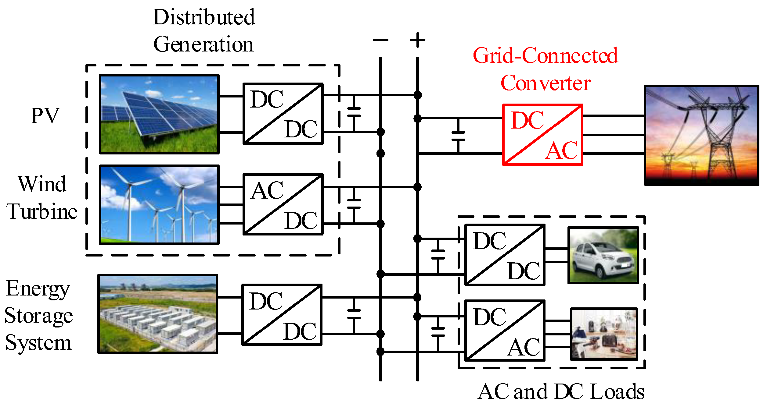
Figure 2.
Grid-connected converter topology.
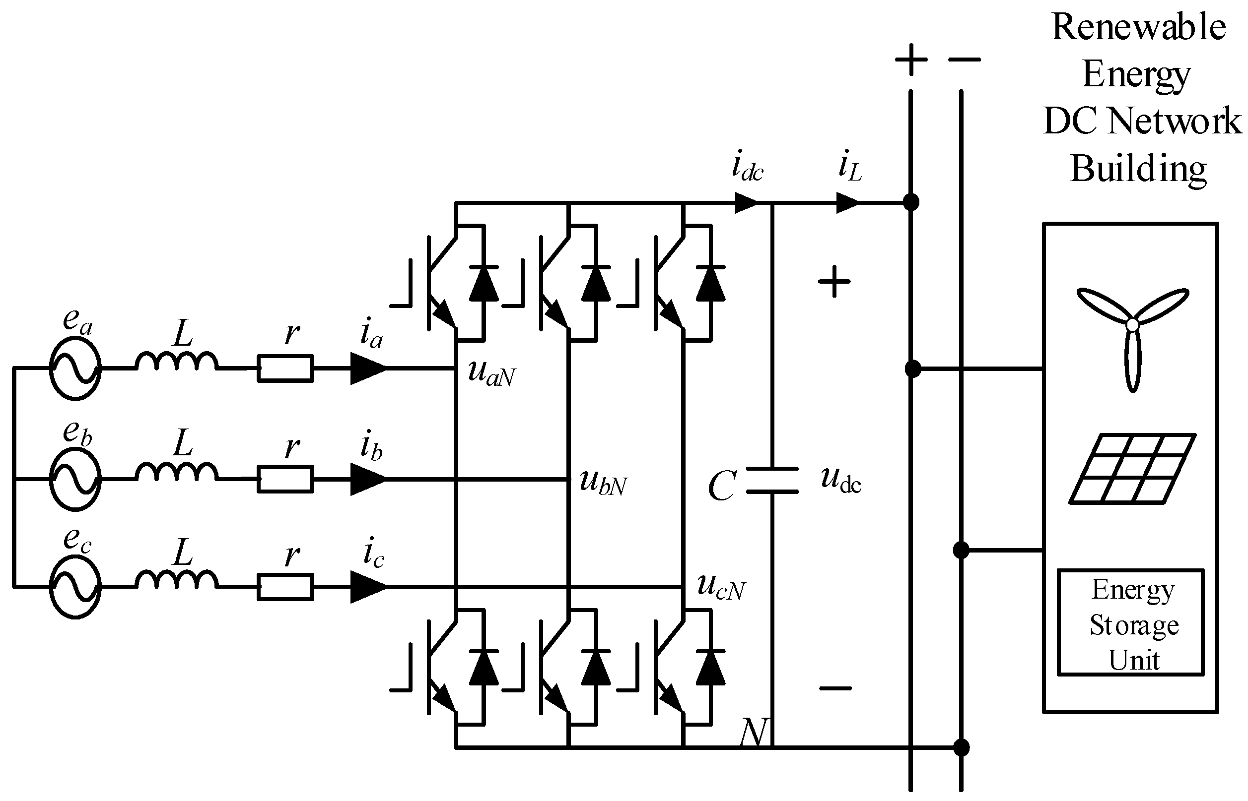
Figure 3.
Grid-connected converter linear model structure.
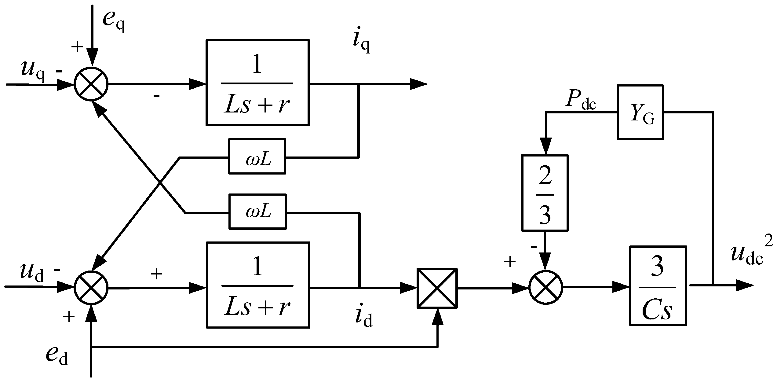
Figure 4.
Grid-connected converter general control structure diagram.
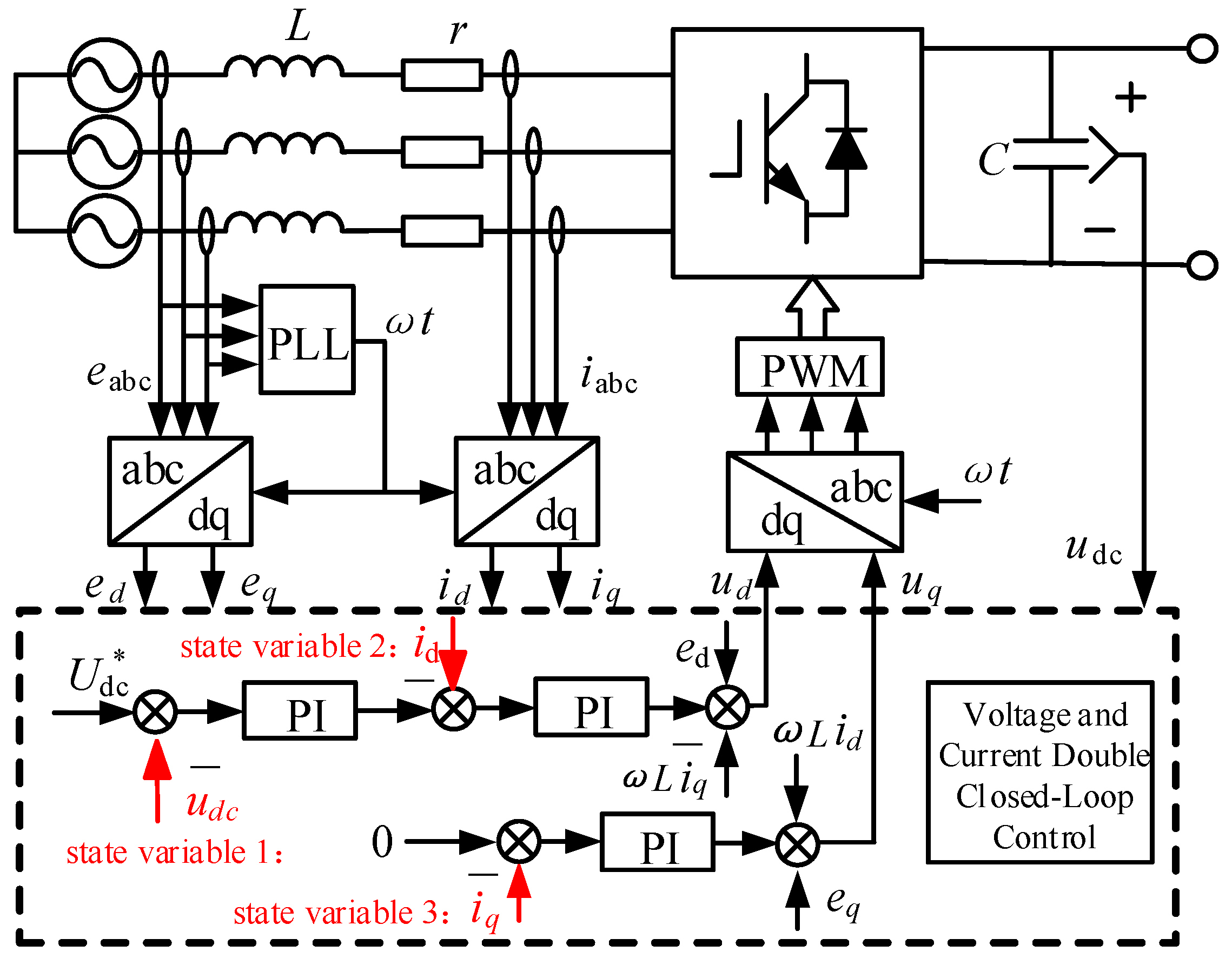
Figure 5.
Block diagram of traditional PI control double-closed-loop.
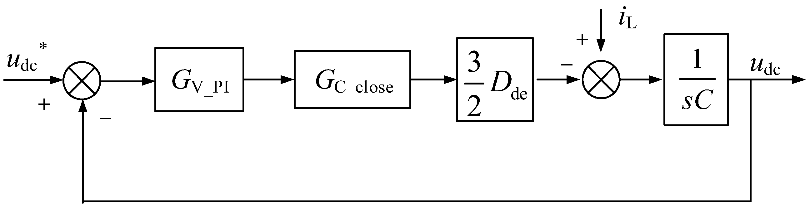
Figure 6.
PI parameter adjustment zero and pole motion trajectory diagram.
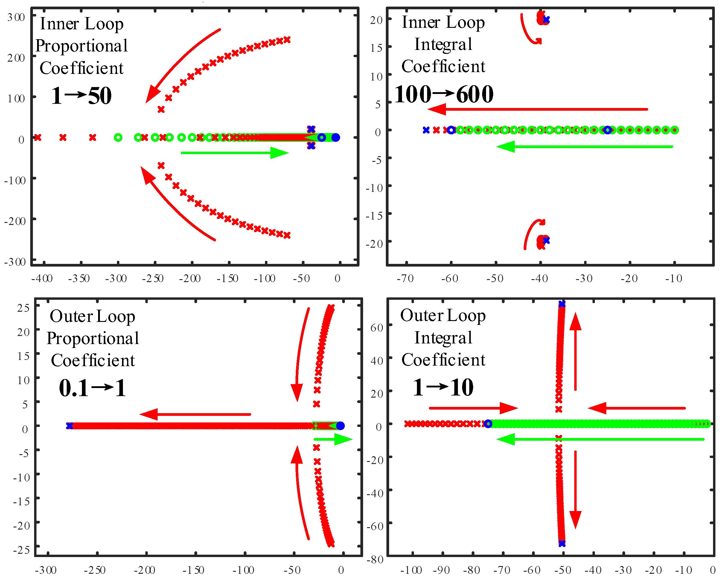
Figure 7.
Introducing integral single-loop state feedback control structure diagram.
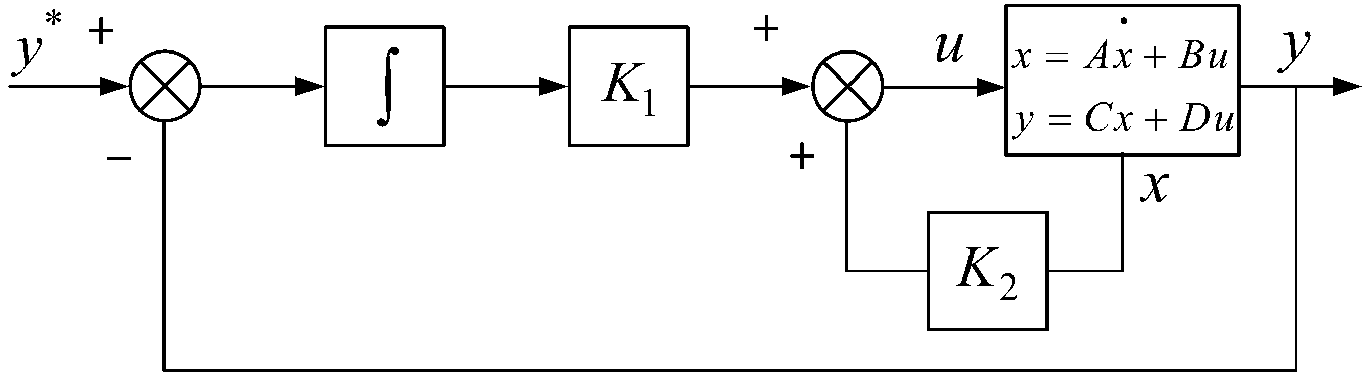
Figure 8.
Single-loop state feedback control strategy of grid-connected converter.
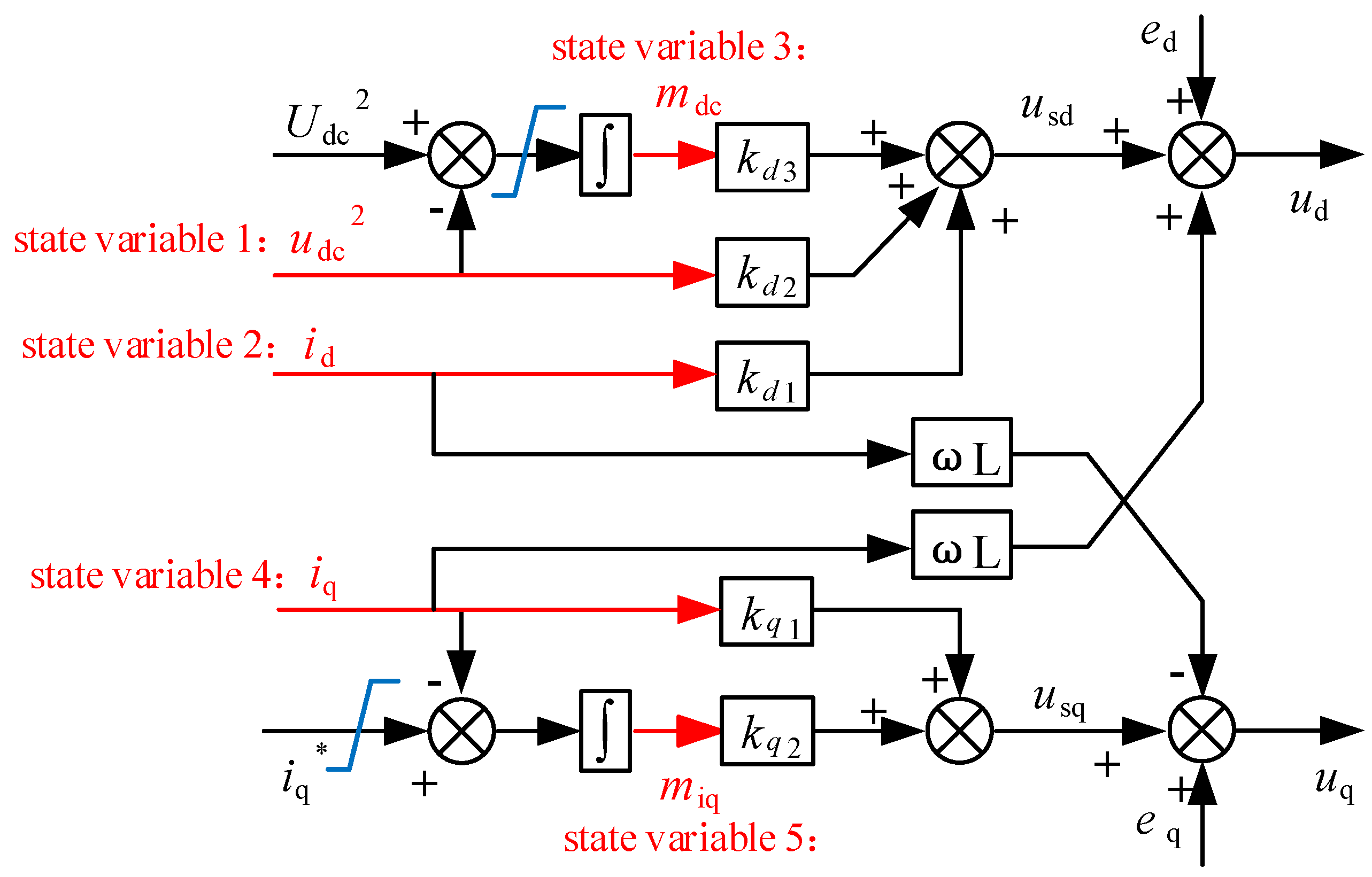
Figure 9.
Limiting design.
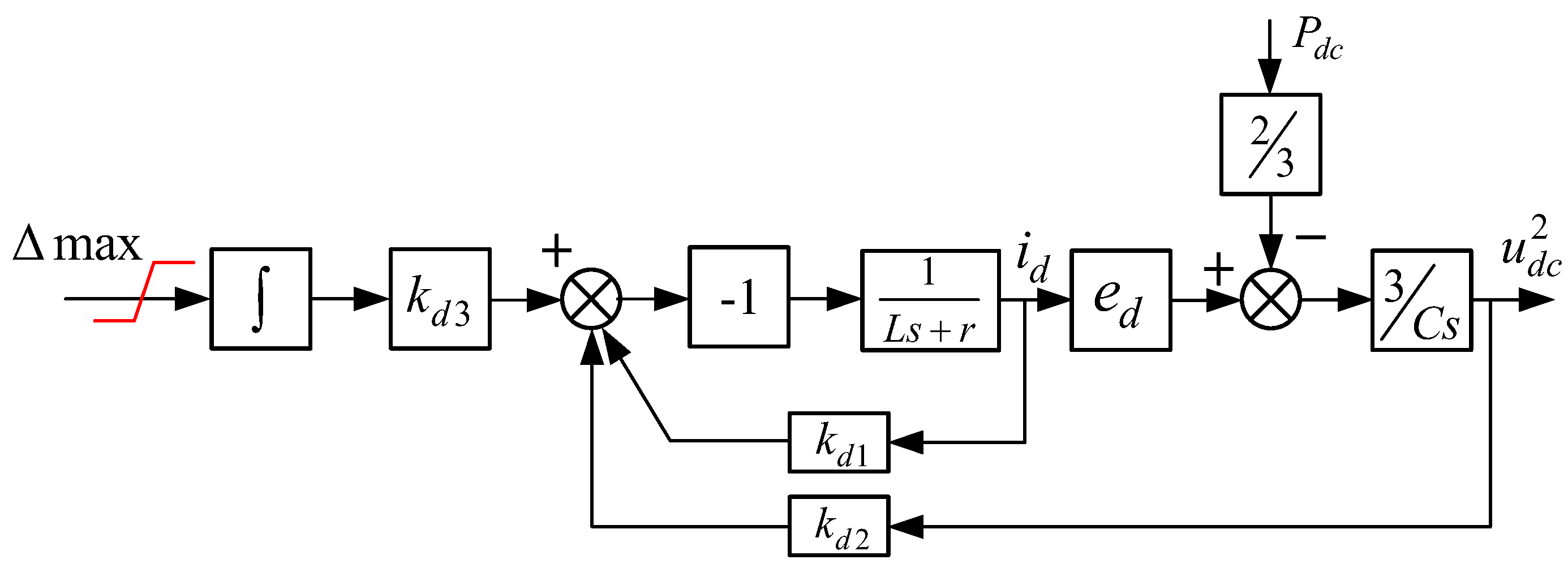
Figure 10.
Pole configuration mode.
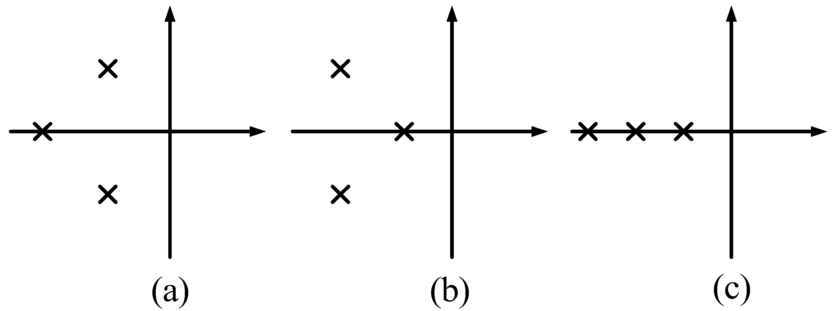
Figure 11.
Pole placement area.
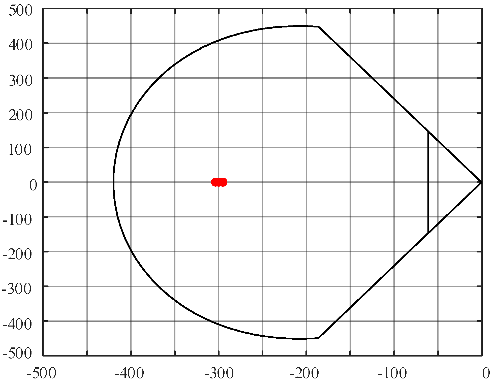
Figure 12.
Bode diagram comparison.
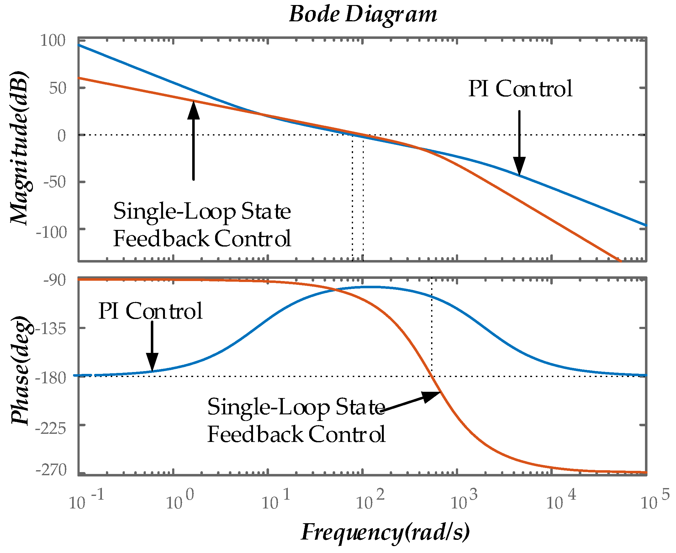
Figure 13.
Change the PI parameter step response diagram.
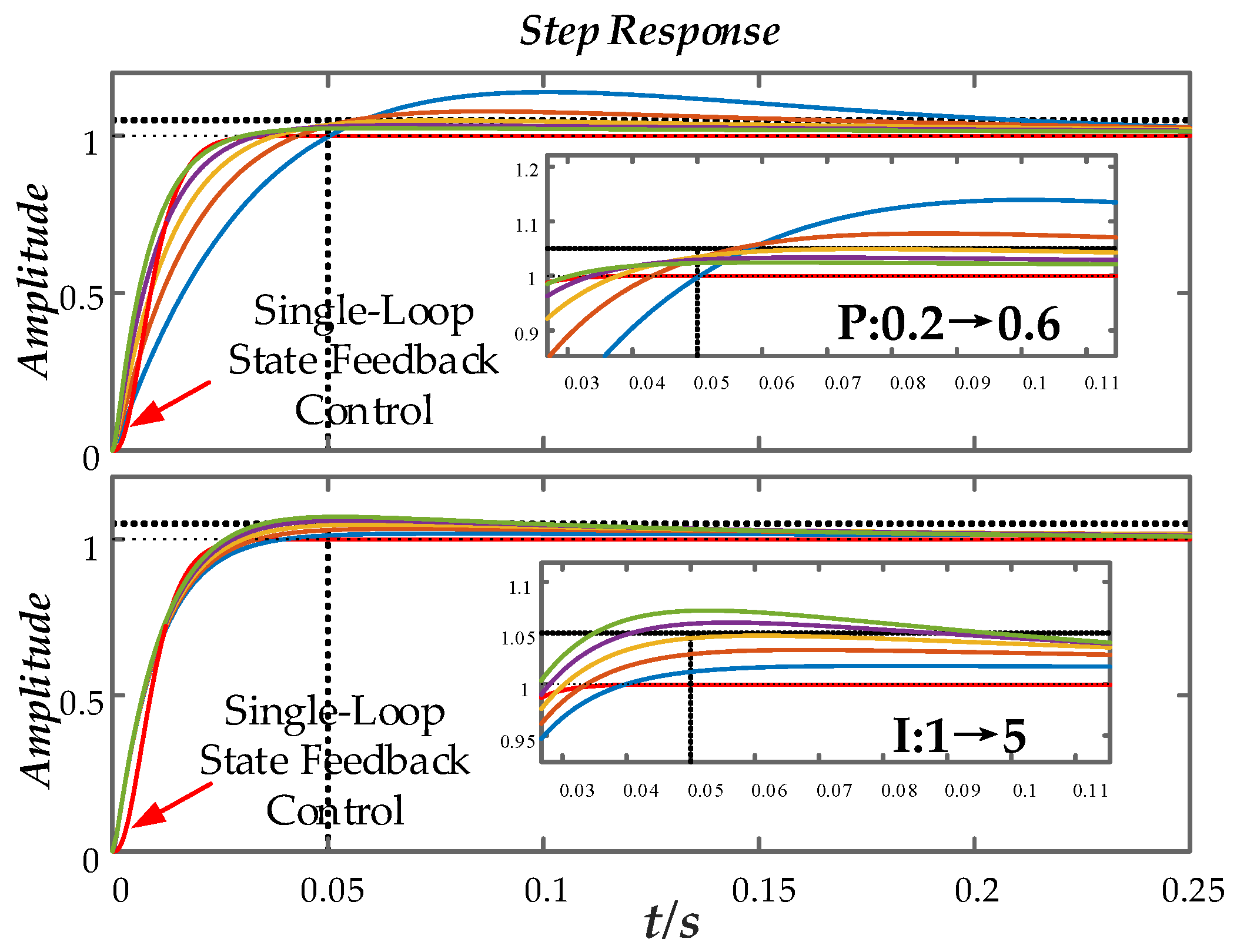
Figure 14.
Comparison of anti-disturbance Bode diagrams of two control strategies.
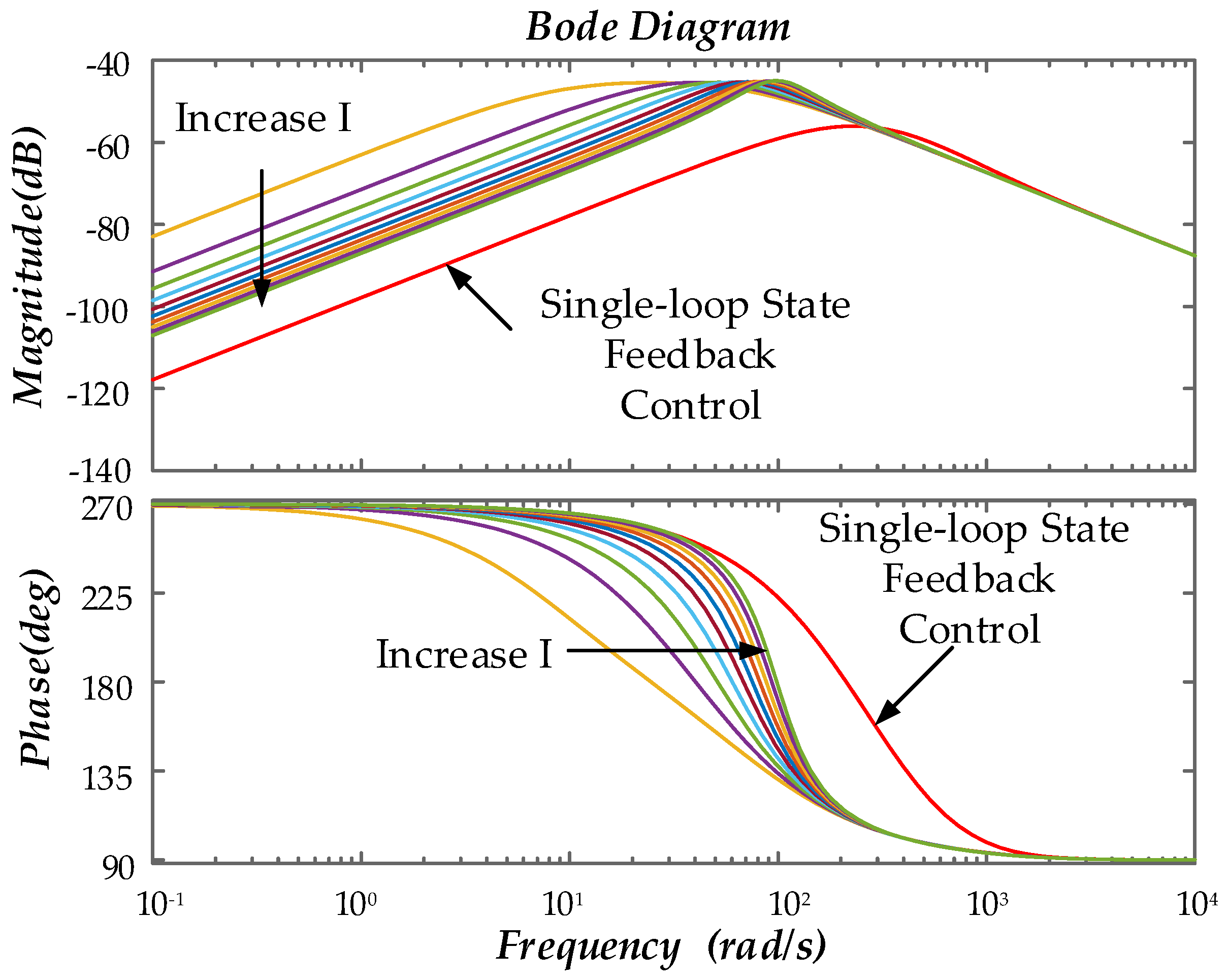
Figure 15.
Pole offset diagram under the condition of parameter change.
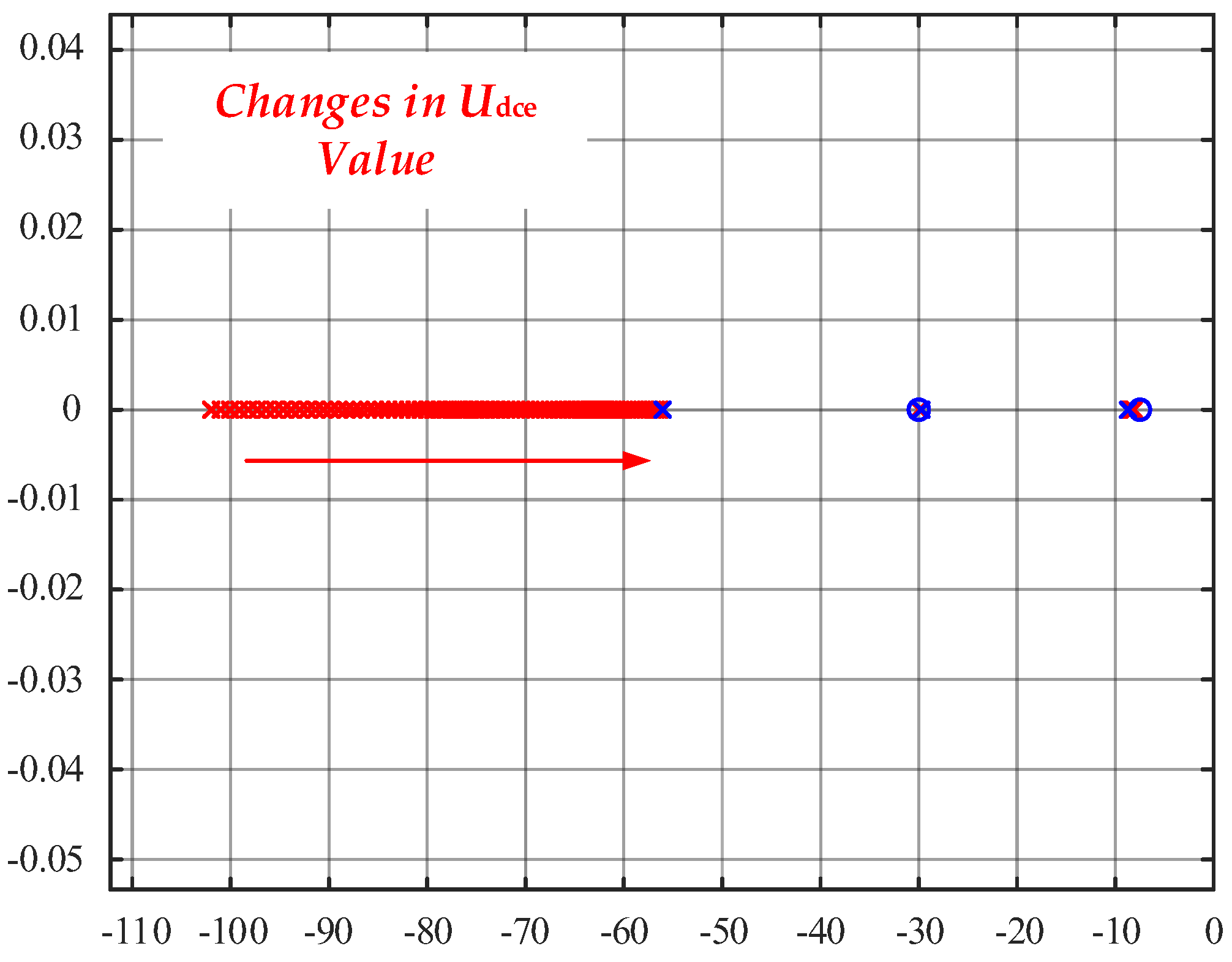
Figure 16.
The outer loop PI parameters change the bus voltage step response.
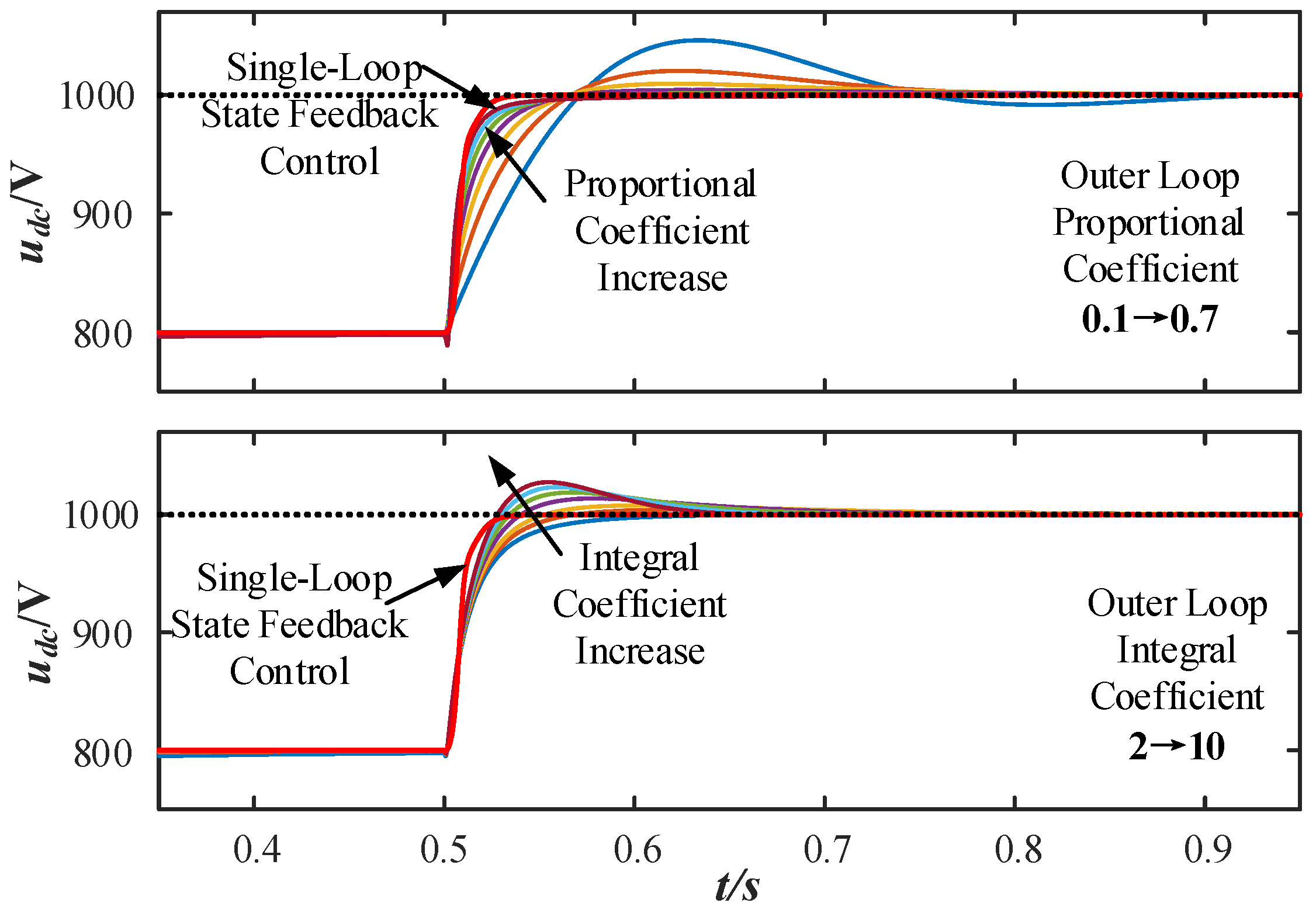
Figure 17.
Bus voltage fluctuation under power disturbance.
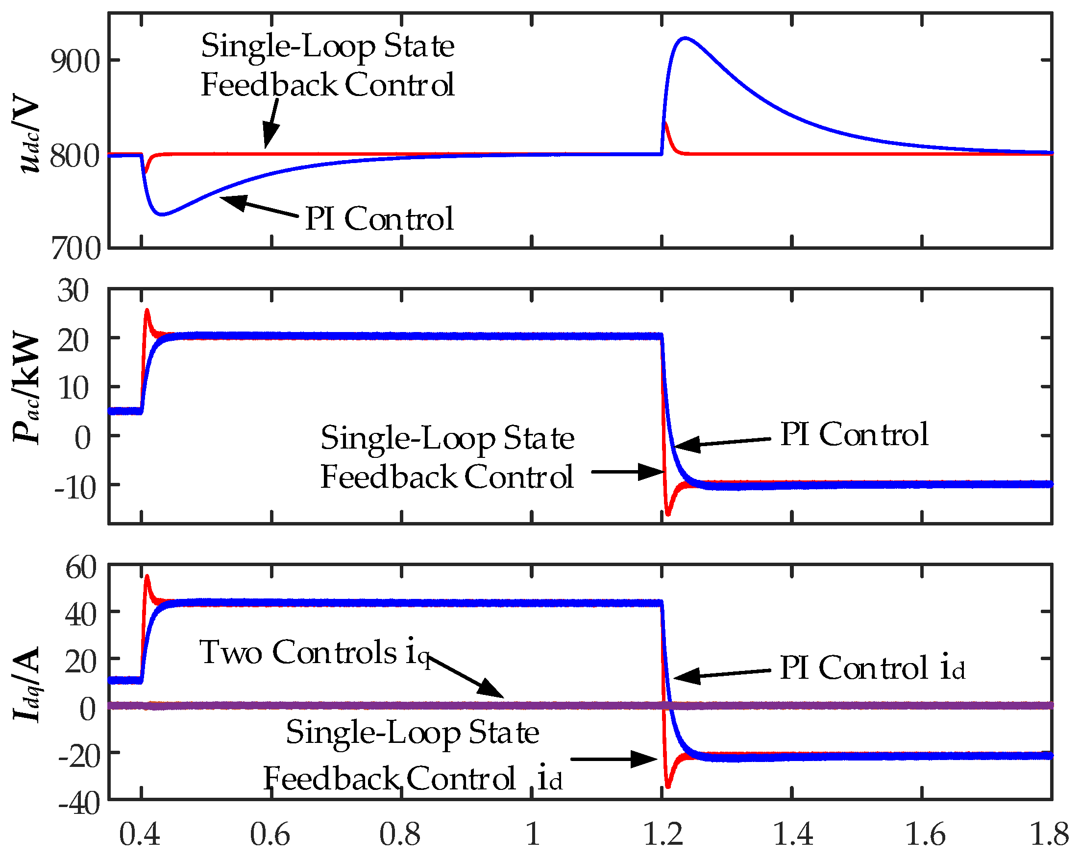
Figure 18.
Comparison of voltage step response and disturbance characteristics with variable integral parameters.
Figure 18.
Comparison of voltage step response and disturbance characteristics with variable integral parameters.
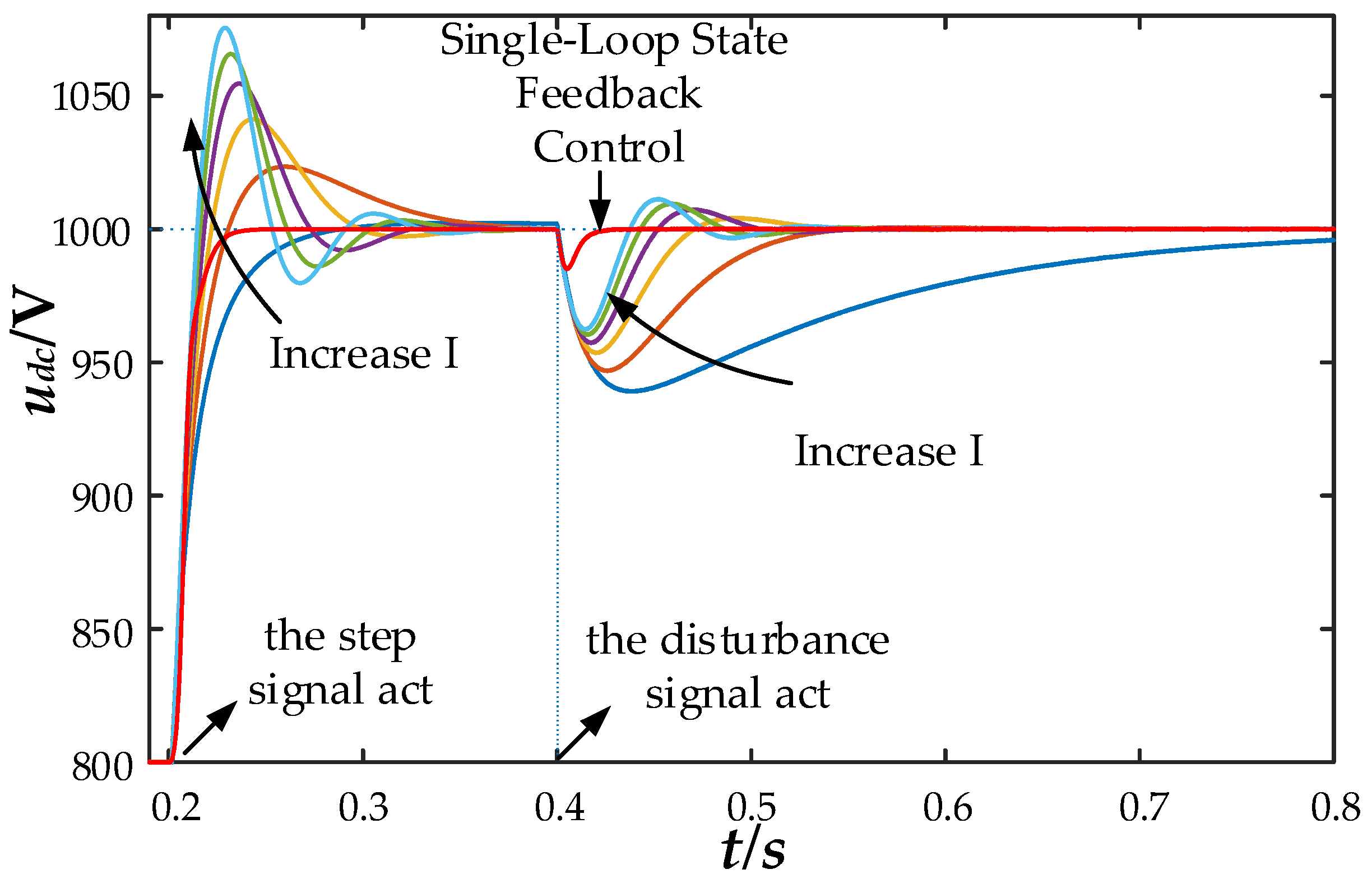
Figure 19.
Comparison of voltage step response and disturbance characteristics with variable integral parameters (a) DC-side capacitor variation response curve; (b) AC-side filtering inductor variation response curve; (c) Grid voltage variation response curve.
Figure 19.
Comparison of voltage step response and disturbance characteristics with variable integral parameters (a) DC-side capacitor variation response curve; (b) AC-side filtering inductor variation response curve; (c) Grid voltage variation response curve.
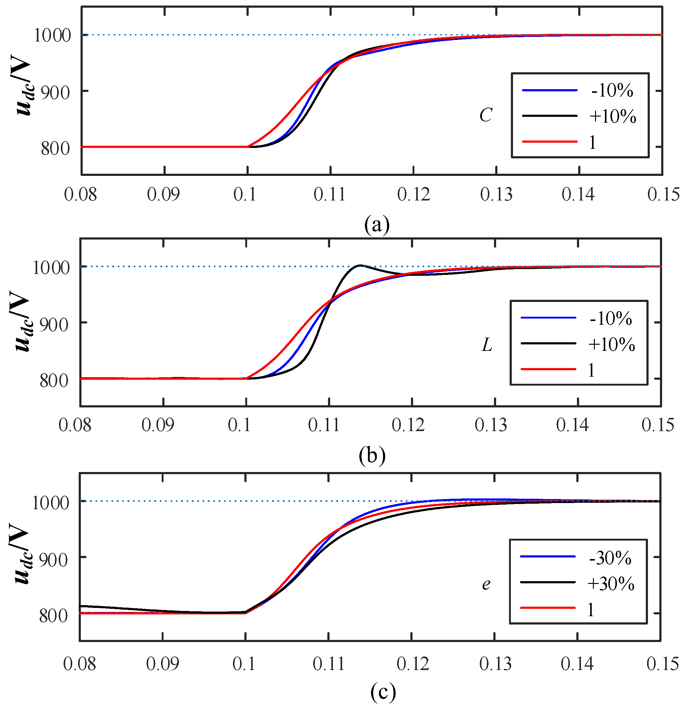
Figure 20.
Experimental hardware configuration.
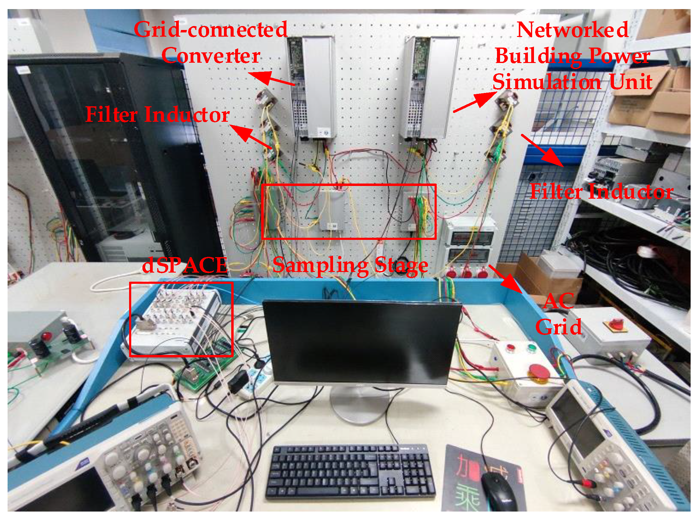
Figure 21.
Diagram of the experimental system.
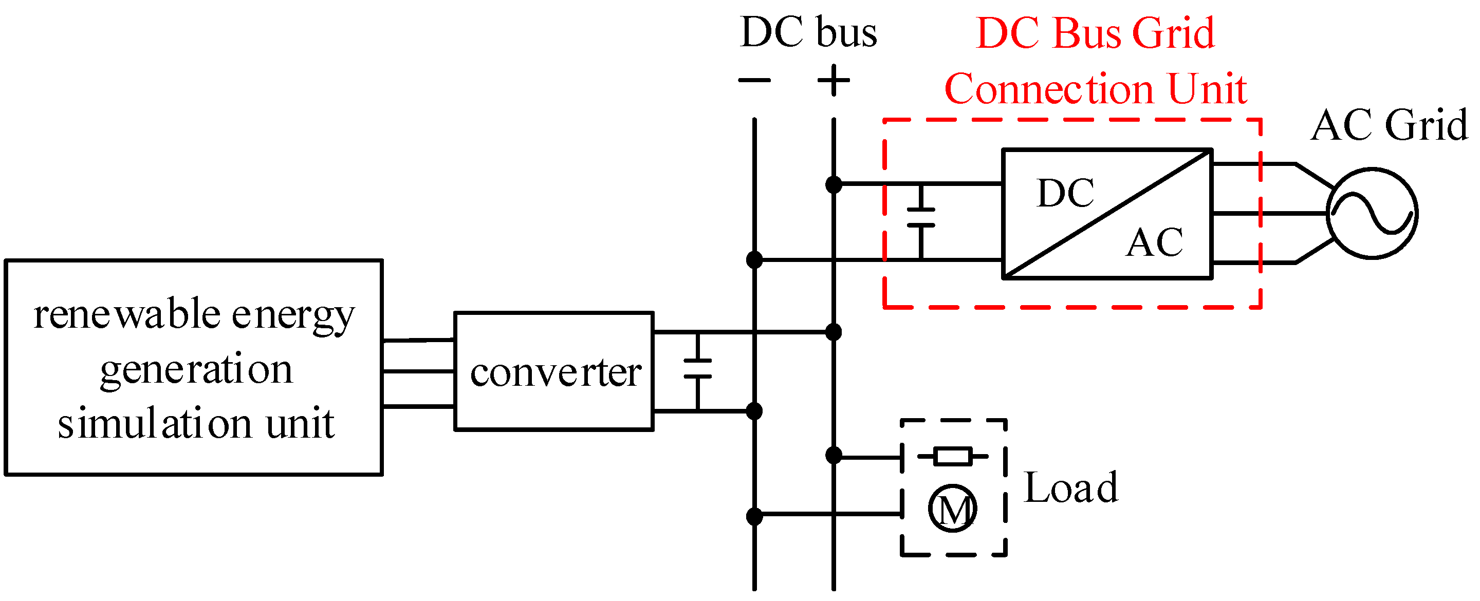
Figure 22.
Comparison of experimental results of the dynamic characteristics of two control strategies (a) Step response of grid-tied converter under PI control; (b) Step response of AC/DC converter under single-loop state feedback control.
Figure 22.
Comparison of experimental results of the dynamic characteristics of two control strategies (a) Step response of grid-tied converter under PI control; (b) Step response of AC/DC converter under single-loop state feedback control.
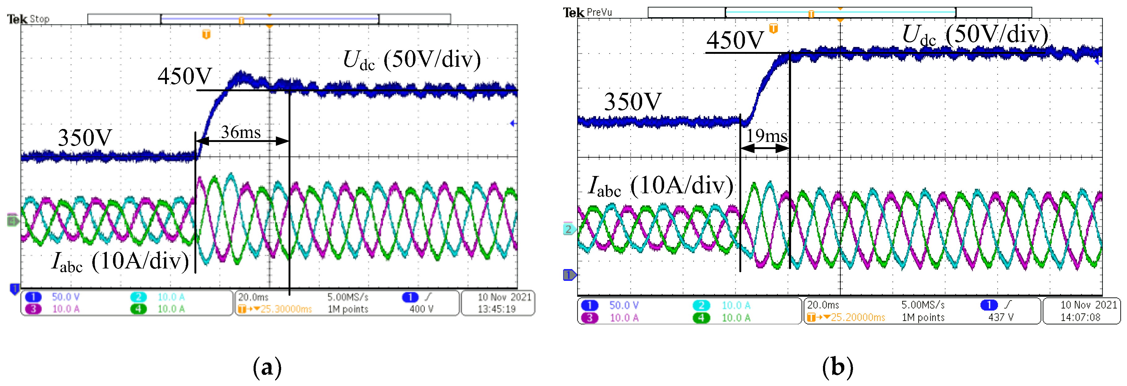
Figure 23.
The voltage step response of changing PI parameters.
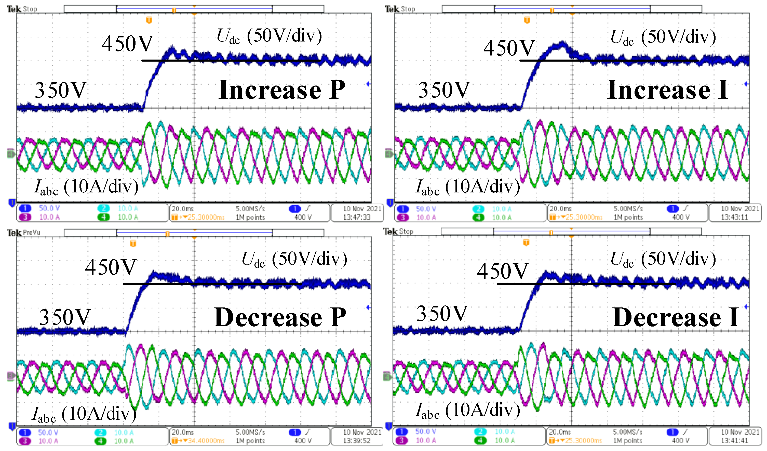
Figure 24.
Comparison of dynamic characteristics between two control strategies after adjustment (a) Step response of grid-tied converter under adjusted PI control; (b) Step response of grid-tied converter under adjusted single-loop state feedback control.
Figure 24.
Comparison of dynamic characteristics between two control strategies after adjustment (a) Step response of grid-tied converter under adjusted PI control; (b) Step response of grid-tied converter under adjusted single-loop state feedback control.
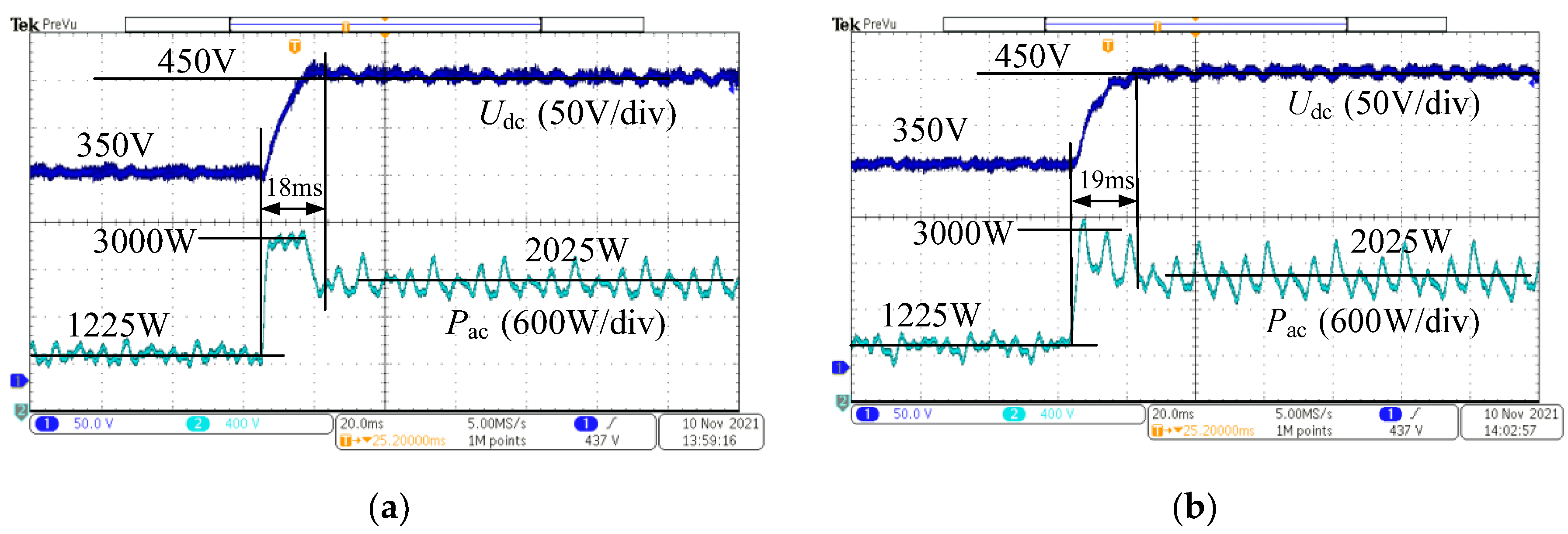
Figure 25.
Comparison of bus voltage fluctuation between two control strategies when transmitting forward power (a) Bus voltage fluctuations under PI control; (b) Bus voltage fluctuations under single-loop state feedback control.
Figure 25.
Comparison of bus voltage fluctuation between two control strategies when transmitting forward power (a) Bus voltage fluctuations under PI control; (b) Bus voltage fluctuations under single-loop state feedback control.

Figure 26.
Comparison of bus voltage fluctuation between two control strategies when transmitting reverse power (a) Bus voltage fluctuations under PI control; (b) Bus voltage fluctuations under single-loop state feedback control.
Figure 26.
Comparison of bus voltage fluctuation between two control strategies when transmitting reverse power (a) Bus voltage fluctuations under PI control; (b) Bus voltage fluctuations under single-loop state feedback control.
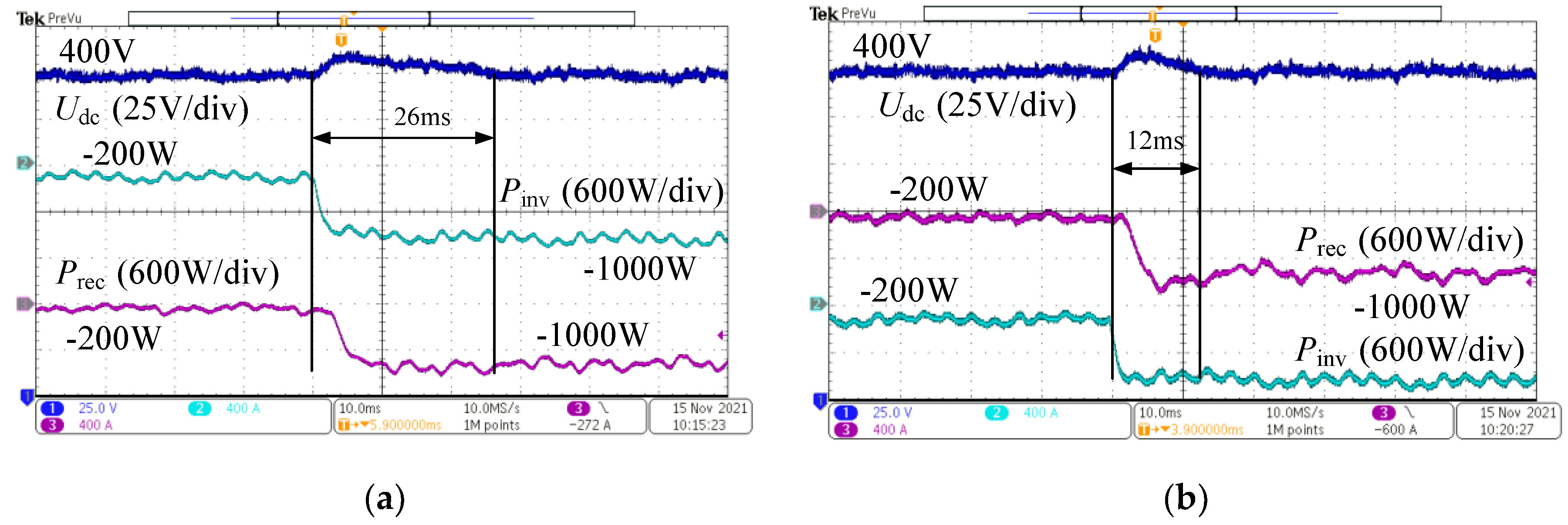
Figure 27.
Single-loop state feedback control voltage step response when reducing inductance.
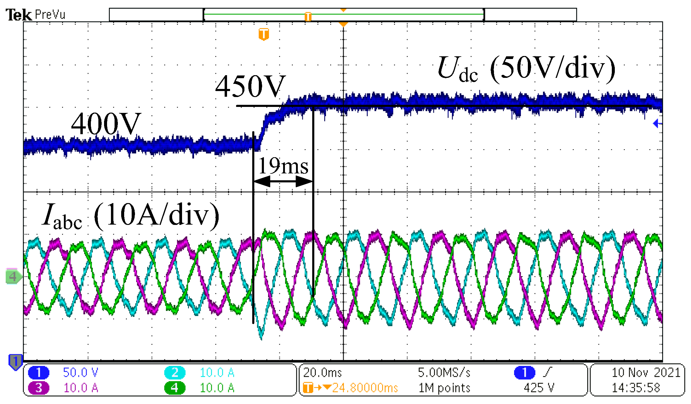
Figure 28.
Single-loop state feedback control voltage step response when changing grid voltage (a) Step response of voltage under single-loop state feedback control when reducing grid voltage; (b) Step response of voltage under single-loop state feedback control when increasing grid voltage.
Figure 28.
Single-loop state feedback control voltage step response when changing grid voltage (a) Step response of voltage under single-loop state feedback control when reducing grid voltage; (b) Step response of voltage under single-loop state feedback control when increasing grid voltage.
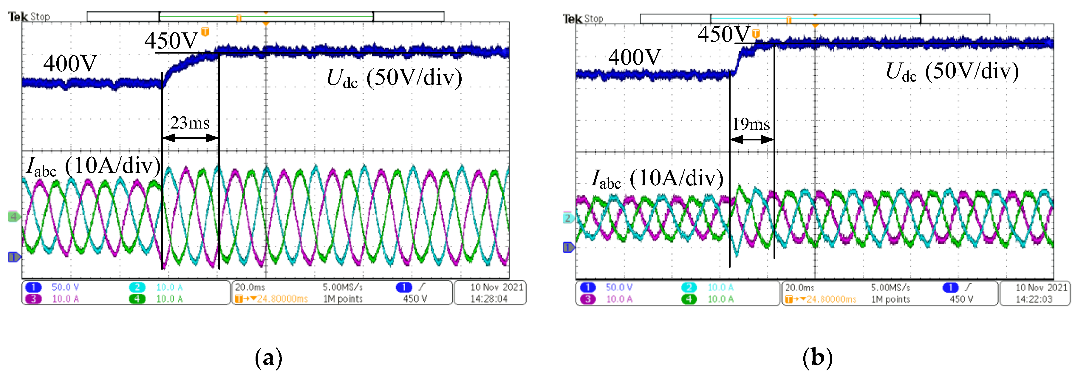

Table 1.
PI control parameter table.
| Control Loop | Proportional Coefficient K | Integral Coefficient I |
|---|---|---|
| Current Loop | 10 | 300 |
| Voltage Loop | 0.4 | 3 |
Table 2.
The main parameters of experiment.
| Parameters | Values | Parameters | Values |
|---|---|---|---|
| Design Power P/kVA | 3 | Bus Voltage | 400 |
| AC Phase Voltage | 110 | DC-Side Capacitance | 400 |
| Connecting Inductance | 7.7 | Inductor Equivalent Resistance | 0.15 |
| Resistive Load | 100 | Switching Frequency | 10 |
| Proportional Coefficient of Voltage Outer Loop | 0.3 | Integral Coefficient of Voltage Outer Loop | 20 |
| Proportional Coefficient of Current Inner Loop | 10 | Integral Coefficient of Current Inner Loop | 400 |
| Single-Loop State Feedback Control d-Axis Poles | -503,-502,-501 | Single-Loop State Feedback Control q-Axis Poles | -503,-502 |
Disclaimer/Publisher’s Note: The statements, opinions and data contained in all publications are solely those of the individual author(s) and contributor(s) and not of MDPI and/or the editor(s). MDPI and/or the editor(s) disclaim responsibility for any injury to people or property resulting from any ideas, methods, instructions or products referred to in the content. |
© 2024 by the authors. Licensee MDPI, Basel, Switzerland. This article is an open access article distributed under the terms and conditions of the Creative Commons Attribution (CC BY) license (http://creativecommons.org/licenses/by/4.0/).
Copyright: This open access article is published under a Creative Commons CC BY 4.0 license, which permit the free download, distribution, and reuse, provided that the author and preprint are cited in any reuse.


