
Submitted:
25 September 2024
Posted:
25 September 2024
You are already at the latest version
Abstract
Humanity is shifting its power generation to renewable energy, notably wind power. As more and more wind power plants are built, it has become important to improve the efficiency of wind power generation and reduce the manufacturing costs of wind power equipment. The mechanical multiplier gearbox is one of the most important parts of the wind power turbine, and it is now being built as a planetary gear train as these gearboxes offer a compact build capable of high power ratings in a relatively small package with coaxial input and output shafts. It is very important to select the right kinematic scheme and the other relevant parameters in the early design stages as the wrong kinematic scheme will result in a suboptimal solution. This article deals with the selection of the optimal gearbox solution for a 700 kW wind turbine application, taking into account both two-carrier and three-carrier gearbox solutions. As the optimal solution may be deducted only by systematic analysis, the proprietary 2-SPEED software has been developed for this purpose. The results of the analysis have been presented in this article, and optimal gear train solutions have been suggested for both two-carrier and three-carrier multiplier configurations.
Keywords:
epicyclic gear train
; complex planet carrier gear train
; multiplier gearbox
; comparative analysis
; wind power generation
; renewable energy
; sustainable development (max 10)
1. Introduction
Energy is the keystone for the development of any civilization. However, the generation of energy comes at a price, as resources must be spent. As human civilization has developed using fossil fuels so far, the price of progress must be paid in the form of climate changes and global warming. The influence of these changes may be mitigated, reduced, or their rate slowed down by performing a change to renewable and therefore sustainable energy sources [1,2,3,4,5].
Wind power has been historically known as a source of renewable mechanical energy, and nowadays wind turbines are being built to harness wind power to produce electricity.
As the wind turbine is a machine extracting power from a fluid in motion, its primary efficiency is constrained to 59,3% of the energy of the incoming fluid by Betz’s law, and contemporary designs can extract up to 80% of this amount [6]. Further inefficiencies that are hard to mitigate, such as turbine blade and rotor losses, generator losses, turbine blade losses, and power transmission losses [7,8] point to the turbine gearbox as the primary component that can be used to improve the power efficiency of a wind turbine.
As the wind turbine operates at a relatively low number of revolutions per minute, a multiplier gearbox is required to turn the generator shaft at a speed acceptable for power generation [9,10,11,12]. Historically, this was achieved by a multi-stage gearbox, however these tend to be heavy, cumbersome and require multiple stages as gear pairs are practically restricted to ratios of about 8:1 in a single stage, or 0,125 when operating as a multiplier.
The gearbox performance may be enhanced with improved bearing systems [13,14], by increasing the accuracy and machining quality of the gears [15], and by switching to epicyclic gearboxes using planetary gearsets as its components. Epicyclic gearboxes offer considerable advantages, notably a reduced weight and increased loading capacity due to multiple gears in mesh at the same time [16,17,18,19]. Furthermore, single-stage gearboxes of this type may be built for gear ratios up to 12:1 (multiplication 0,0833), and even more may be achieved by opting for two, three or even four-carrier boxes. The only downside of these advanced gearboxes is that they require specialized calculation procedures to establish whether the gearbox design is kinematically feasible, and whether the box can operate as a multiplier with a satisfactory efficiency ratio.
The advantages of the application of epicyclic (planetary) gear trains in relation to conventional gear trains [20,21], such as reduced size and increased resistance to wear and tear occurring in conventional gearboxes [22]. The application of planetary gear drives has significantly expanded into various engineering products such as, but not limited to, drives and actuators in robotics, machine tool drives, vessel propulsion, railway vehicles, aircraft main drives etc. [23,24,25,26,27].
For example, planetary drives are common in both fixed-wing and rotary-wing aircraft due to their compact size and reliability, while machine tools might use a more complex drive to provide reversing capability in cases where it is impractical to stop and reverse the main motor. Furthermore, as planetary drives may be built to be controlled using brakes and/or clutches, they may be used as shifting gearboxes in propulsion applications, especially when dealing with hybrid or electric vehicles [25,28,29,30]. Additionally, when dealing with applications that require a single transmission ratio, a simpler gearbox permanently locked to a single gear ratio is employed.
The purpose of this article is to conduct an analysis and optimization of a multi-stage multiplier gearbox for the operation of a windmill power turbine. Based on the application constraints, various design solutions are generated and analyzed using the purpose-developed software, after which optimized two and three-carrier epicyclic gearbox solutions are discussed, and an optimal solution proposed.
2. The Epicyclic Gear Train
A schematic of the basic epicyclic gear train, 1AI according to the German classification system, 2k-h, type A according to Kudryavtsev, or according to Arnaudov and Karaivanov, can be seen in Figure 1.
The gear train is displayed with its Wolf-Arnaudov symbol and the specific torques acting on its shafts [31]. The gear train is of relatively simple construction, its parts being the sun gear 1, annulus or ring gear 3, three or more planet gears 2, and the planet carrier h. It is also commonly used as a component of complex gear trains [32].
The ideal torque ratio t of the gear train is given by Equation 1, the shaft torque ratio is given by Equation 2, where z1 is the number of sun gear teeth, z3 is the number of ring gear teeth, T1 is the torque on the sun gear shaft, T3 the torque on the ring gear shaft, TH the torque on the planet carrier shaft, and i0 is the internal transmission ratio:
The different lines of the Wolf-Arnaudov symbol correspond to gearset shafts, notably the thin line to the sun gear shaft, the thick line to the ring gear shaft, and finally the double line to the planet carrier shaft. The thickness of the lines also corresponds to the intensity of the torques acting on the gear train shafts; T1 and T3 are equidirectional external torques of different size, while TH is the largest torque, equal to the absolute value of the sum of the other two torques and therefore marked with a double line.
A multi-carrier gear train is created by connecting the shafts of its basic gear trains. As this paper deals with two and three-carrier gear trains, one-speed, two-carrier trains with three external shafts composed of two basic component trains will be considered, while three-carrier gear trains will be created by series connecting a two-carrier train with a simple component train. As the two-carrier trains do not need to have shifting capabilities, two-carrier trains with three external shafts will be used, having two single and one connecting shaft, the fourth connecting shaft being internal, as schematically shown in Figure 2.
Some two-carrier trains are capable of high transmission ratios while maintaining a reasonably high overall efficiency. Figure 3 schematically shows the symbol of an actual two-carrier gear train with external shaft torques (TW, TN and TE) labelled following the cardinal directions (W, N, E). The symbol also contains the ideal torque ratios (tI and tII) and efficiencies (η0I and η0II) of its respective components.
An overview of possible structures of two-carrier single speed gear trains is provided in Figure 4 [34], showing that the basic component trains may be combined to create 36 different gear trains. However, some layouts are isomorphous, reducing this to 21 practical layouts. Every gear train is capable of six different operating modes, as the reactive element may be any external shaft, with the remaining two external shafts acting as input and output.
To sum up, 126 (21 layouts x 6 operating modes = 126) different transmission variants may be achieved [34]. A matrix type designation is used to mark the scheme and operating mode (e. g. S36 – line 3, column 6). The power input and output are marked by cardinal directions, while the reactive stationary element is placed in parentheses. For example, S26WE(N) points to layout 26 with power input being in the west, power output being in the east, and the northern shaft locked. It must be also pointed out that the naming convention assumes that the internal connecting shaft is always placed at the south (S).
3. Methods
The torque method was used to calculate the transmission ratios of the two-carrier gearsets discussed in this article, as other methods are either too complex to implement (Willis method), or too imprecise when dealing with complex two-carrier trains (Kutzbach method). As there are 126 possible different transmission variants, a specialized software package, 2-SPEED was developed to select the most adequate gear train layout and determine its characteristics in accordance with the imposed design parameters.
3.1. Torque Method
The torque method is a clear, precise, and easy-to-use method for the analysis of epicyclic gear trains. Unlike the previously mentioned methods, it has the advantage that internal branching or circulation of power may be detected, and the gear train efficiency and load calculated reliably. In contrast to the other methods using angular velocity ω and the peripheral linear velocity v, the torque method uses the torques T acting on the gear train components through a lever analogy [31,34,35], which is best explained on the simple planetary gearset from Figure 1.
Equation 3 is imposed by the conditions of the balance of ideal torques acting on the shafts:
The sum of powers in the case of operation with one fixed shaft (1-DOF) can be expressed using Equation 4:
where P, T and ω respectively denote the power, torque and angular velocity, while index A marks the input and index B the output shaft. Equation (4) is then used to determine the transmission ratio (kinematic), Equation 5:
In the case that losses are taken into consideration using the real output torque TBreal, Equation 5 is rewritten to account for losses in the actual gear train, Equation 6:
The efficiency, Equation 7, is calculated in the following manner:
The S55NE(W) gear train operating as a reducer (Figure 5) will be used to demonstrate structural analysis.
The equations for the calculation of the ideal (white background) and real (gray background) specific torques acting on all PGT shafts have been provided by application of Equations 1, 2, 6 and 7 to the PGT. Red solid lines are used to indicate the absolute power flow, while the green dashed lines denote the relative power flow within the PGT [31]. Power flow is from input A to output B, with PA denoting input shaft power and PB denoting output shaft power. Analysis has also shown that this PGT exhibits power circulation.
The overall transmission ratio for reducer mode is provided by Equation 8:
The relation of the PGT efficiency to the ideal torque ratios (tI, tII) and internal efficiencies (η0I, η0II) of the component gear trains for reducer operation is given by Equation 13:
As it is common knowledge that the transmission ratio of a multiplier gear train is the reciprocal value of that same train operating as a reducer, Equation 8 is rearranged for multiplier operation in the form of S55EN(W), Equation 10:
Equation 9 will be rearranged for S55EN(W) in a similar way while taking into consideration that reciprocal efficiency values must be used, Equation 11:
A quick comparison of Equations 9 and 11 shows that Equation 11 is not an exact inverse of Equation 9, but instead confirms that the same planetary gear train can have considerably different efficiency equations for differing power flow directions. This can be demonstrated by assuming a known working combination for S55NE(W), with tI = 6,667, tII = 7,833 and η0I = η0II = 0,98. The result of Equation 8 equals i = -50,506, while Equation 10 yields i = -0,0198. The efficiency according to Equation 9 equals η = 0,797, while the result of Equation 11 yields η = 0,747.
Equations 8-11 have been integrated into the multiplier gear calculation subsystem of the 2-SPEED software package and are used to calculate the transmission ratio and overall efficiency of the S55NE(W) PGT. The calculations made for the purposes of this article have been performed under the assumption of η0I = η0II = 0,98 as any component gearset can be brought to this level of efficiency with accurate machining [11].
3.2. 2-SPEED Software Package
The 2-SPEED software package with a specially developed multiplier gear calculation subsystem was used to identify viable gearbox solutions under application constraints, and its principle of operation must be explained.
The 2-SPEED program was originally developed to identify the variants of two-carrier PGTs and their parameters that fulfil the kinematic requirements of the application. The program searches for valid solutions, and the solutions are listed in the order of user determined priority, such as maximum efficiency, minimum weight, or minimal size. The program is also capable of multi-criteria optimization as the optimization criteria do not have to be equally important. The weighted coefficient method is used to represent the importance of every criterion, as every two-speed drive may be built using several combinations of basic component gear trains. The program can calculate one-carrier gear trains and two-carrier gear trains operating as two-speed or single-speed gearboxes. Gear trains with more than two carriers are calculated by combining single-carrier and two-carrier outputs. The multiplier subsystem adds the possibility to calculate multiplicator drives as normally only reducer solutions are considered. A flow diagram of the software can be seen in Figure 6.
The program operates by checking the ideal torque ratios of every possible combination of basic component gear trains and keeps only those that provide the required transmission ratio. The range of the ideal torque ratios is determined by design limits, notably the number of planet gears per component gear train. The transmission ratio is calculated for every possible combination of ideal torque ratios and is checked whether it is within the tolerance range for the desired transmission ratio. The ideal torque ratios are represented using the numbers of teeth on sun and ring gears for both component gear trains, Equation 12 and Equation 13:
The tooth numbers of the sun gears z1I and z1II must be imposed by the user. The program will then enlarge one ring gear by one tooth and check whether the basic component gear train satisfies the assembly conditions. If it does not, the corresponding ideal torque ratio is discarded, and the ring gear enlarged by one more tooth. The procedure is repeated, and valid ideal torque ratios are registered until the maximum allowable ideal torque ratio for that component gear train is reached. The same procedure is repeated on the second basic component gear, creating a set of possible transmission ratios.
The values of different parameters are calculated and stored for each valid member of the set of ratios (basic component gear train geometry, component efficiency, transmission ratios, overall efficiency etc.) as a function of the ideal torque ratios of the component gear trains tI and tII. The best gearbox variant for the application is selected from the dataset, whether according to a single criterion, or by multi-criteria optimization. For multi-criteria optimization, the weighting coefficients for each optimization criteria must be determined according to the application conditions, depending on the importance of the criterion.
All layout variants must be validated by creating a kinematic scheme to check out whether the solution is kinematically valid, and that it meets the relevant design and technological criteria. This will enable the best variant to be selected.
The program has been coded as a 32-bit console application using Fortran 95. A full calculation cycle required to prepare data ready for kinematic validation takes about 3 to 5 minutes on a contemporary PC. The program running time can be significantly extended by additional calculations, such as variation of the numbers of the teeth of the sun gears or variation of the numbers of the planet gears. Most of the running time, however, is spent on post-processing and sorting of valid ideal torque pairs according to the optimization criteria.
The software is also capable of calculating the component gear train internal efficiencies η0I and η0II based on the number of teeth of the respective sun gear z1, the ideal torque ratio of the component PGT t, and the coefficients of churning losses kc, planet bearing losses kb and seal frictional losses ks, using the expressions from [33].
4. Results
A twofold approach was decided for the generation of the multiplier reduction gears. In the first approach, the logic of ease of manufacturing was adopted, therefore opting for two-carrier gear trains having the required transmission ratio of i = 0,02. On the other hand, the second approach adopted the logic of minimization of gear train dimensions and weight, therefore a combination of a two-carrier gear train series connected to a simple planetary gear train was used. In this case, the two-carrier gear train was selected to have a transmission ratio of itc= 0,08 and was combined with a simple train having the transmission ratio isc= 0,25. This particular ratio breakup was selected due to isc= 0,25 presenting the optimal design solution of the simple train. In this particular case, the ideal torque ratio of the simple train equals tsc= 3, and the gear train can be built with the sun and planet gears having the same number of gear teeth, significantly reducing the manufacturing complexity. Furthermore, engineering experience has shown that this particular configuration exhibits a particularly high coupling to meshing power transmission ratio, therefore increasing the overall efficiency ratio of the gearbox.
4.1. Two-Carrier Gear Trains
Two-carrier gear trains are commonly used as reduction gears with transmission ratios up to | i | = 169 and as multipliers for the respective inverse ratios, depending on their efficiency. They are in most common use for | i | = 18…90 and feasible inverse ratios [33,36], and therefore present a valid solution for | i | = 0,02. Comprehensive analysis was performed, requiring 126 possible variants to be set up and tested for the required transmission ratio. This work was performed by the 2-SPEED software previously described in Chapter 3.
The resulting gear trains were ranked according to the criteria of minimal mass, minimal larger ring gear reference diameter size and maximum efficiency. The gear trains were ranked separately for positive and negative transmission ratios for clarity. It should be noted here that only gear trains having efficiencies above 90% were considered feasible and examined further.
The gear trains with positive transmission ratios ranked according to the criteria of minimal mass are shown in Table 1, while the gear trains with negative transmission ratios ranked according to the criteria of minimal mass are shown in Table 2.
4.2. Three-Carrier Gear Trains
As previously mentioned, the three-carrier gear trains were obtained by combining two-carrier gear trains having a transmission ratio | i | = 0,08 with a simple planetary having a transmission ratio of i = 0,25. As for simple two-carrier trains, 2-SPEED software was used to analyze and test the 126 possible gear train variants. Valid gear trains were ranked according to the criteria of minimal mass, minimal larger ring gear reference diameter size and maximum efficiency. The gear trains are ranked separately for positive and negative transmission ratios for clarity. Only gear trains with efficiencies above 90% were examined further as before.
The gear trains with positive transmission ratios ranked according to the criteria of minimal mass are shown in Table 7, while the gear trains with negative transmission ratios ranked according to the criteria of minimal mass are shown in Table 8.
5. Discussion and Summary of the Results
Regarding the efficiency of the generated solutions, it must be said here that only the solutions with η = 0 would be locked solid. It is possible for a multiplier to have η < 0, but such solutions would also be locked solid anyway and therefore the program was set to output only for η ≥ 0. Multipliers with η < 0,5 will not be self-locking as they transform into reducers with a relatively large η when driven from the side of the powered machine. Instead, they will generate a large amount of heat in operation. Therefore, for a multiplier to be regarded as feasible, it had to exhibit η ≥ 0,9.
The gear train solutions were searched in two steps by the software program. In the first step, the program generated solutions for every scheme, and then picked the best solution for that scheme if it existed. In the next step, the program searched for the best solution from all schemes picked as best in the previous step. As the program performs a complete search within the design constraints, the program prints out all isomorphous solutions. The diagrams illustrate one set of solutions provided by the program for one set of input constraints.
According to the data from Table 1 and 2, the S26EW(N) and S26NW(E) gear trains provide the best solution both from the standpoint of minimal mass in the category of |i| = 0,02. A more detailed overview of the properties of these gear trains is found in Figure 7.
It is evident that minimal mass is achieved by gearset S26EW(N) with the combination of tI = 6,333 and tII = 5,667 for i = 0,02, while gearset S26NW(E) achieves this with tI = 5,8333 and tII = 7,8333 for i = - 0,02. According to the data from Table 1, S26EW(N) is a clear winner according to the criterion of efficiency in addition to the requested minimum mass criteria, while gearset S26NW(E) is the best solution from Table 2, with S16EW(N) a close second but some 60 kg heavier.
According to the data from Table 3 and 4, the S26EW(N) and S26NW(E) gear trains also provide the best solution from the standpoint of the minimal largest ring gear reference diameter in the category of |i| = 0,02. A more detailed overview of the properties of these gear trains is found in Figure 8.
The minimal largest reference diameter is achieved by gearset S26EW(N) with the combination of tI = 8 and tII = 4,5 for i = 0,02, while gearset S26NW(E) achieves this for tI = 7,8333 and tII = 4,6667 for i = - 0,02. Analysis of the data from Table 3 and Table 4 demonstrates that S26EW(N) and S26NW(E) provide the best solution according to the additional criterion of efficiency, as other solutions that provide a smaller diameter have efficiencies well below 50%.
The best solution from the standpoint of maximum efficiency is provided by the S16NW(E) and S16EW(N) gear trains also provide the best solution even from the standpoint of maximum efficiency in the category of |i| = 0,02, according to the data from Table 5 and 6, with a more detailed overview of the properties of this gearset in Figure 9.
The maximum efficiency is achieved by gearset S16NW(E) with the combination of tI = 8 and tII = 5 for i = 0,02, while this is achieved by gearset S16EW(N) for tI = 8 and tII = 5,1667 in the case of i = - 0,02. Analysis of the data from Table 5 and Table 6 demonstrates that S16NW(E) and S16EW(N) provide the best solution according to the additional criterion of efficiency. For i = 0,02, S16NW(E) has a marginally lower efficiency than the best solution, however it is the best solution from the standpoint of gear train weight and maximum gear train diameter as it is 1700 kg lighter than the highest efficiency solution. For i = - 0,02, S16EW(N) is tied in efficiency with S26EW(N), however S16EW(N) is the better solution as its almost 1300 kg lighter for the same torque input.
According to the data from Table 7 and 8, the S16NW(E) and S26NE(W) gear trains provide the best solution from the standpoint of minimal mass in the category of |i| = 0,08. A more detailed overview of the properties of these gearsets is found in Figure 10.
It is evident that minimal mass is achieved by gearset S16NW(E) with the combination of tI = 3 and tII = 2,8333 for i = 0,08, while gearset S26NE(W) achieves this with tI = 2,6667 and tII = 2,6667 for i = - 0,08. Data from Table 7 suggests that S16NW(E) is a clear winner according to the criterion of minimal mass, while gearset S26NE(W) is the best solution from Table 8 as it offers a smaller maximum ring gear reference diameter than S16EW(N) even though it is some 30 kg heavier.
According to the data from Table 9 and 10, the S16NW(E) and S26NE(W) gear trains also provide the best solution from the standpoint of minimal largest ring gear reference diameter in the category of |i| = 0,08. A more detailed overview of the properties of these gear trains is found in Figure 11.
The minimal largest reference diameter is achieved by gearset S16NW(E) with the combination of tI = 3 and tII = 2,8333 for i = 0,08, while gearset S26NE(W) achieves this with tI = 2,6667 and tII = 2,6667 for i = - 0,08. Analysis of the data from Table 9 and Table 10 demonstrates that S16NW(E) and S26NE(W) provide the best solution even according to the additional efficiency criterion, even though other solutions with acceptable efficiencies exist.
According to the data from Table 11 and 12, the S16NW(E) and S26NE(W) gear trains provide the best solution from the standpoint of maximum efficiency in the category of |i| = 0,08. A more detailed overview of the properties of these gear trains is found in Figure 12.
Analysis of the data from Table 11 and Table 12 demonstrates that S16NW(E) and S26NW(E) provide the best solution according to the criterion of efficiency. The maximum efficiency is achieved by gearset S16NW(E) with the combination of tI = 4,3333 and tII = 1,6667 for i = 0,08, while this is achieved by gearset S26NW(E) for tI = 2 and tII = 3,5 in the case of i = - 0,08.
For i = 0,08, S16NW(E) is tied with S23EW(N) regarding efficiency, and even though S23EW(N) is some 1200 kg lighter, S16NW(E) has a more favorable maximum ring gear diameter ratio, and therefore represents the better solution. For i = - 0,08, S26NW(E) is a clear winner, as it offers the best efficiency combined with minimum mass.
The results are summarized in Table 13. Red signs denote the best solution in the category for |i| = 0,02, while blue signs denote the best solution for |i| = 0,08. It is possible for a gear train to be a multiple best solution as the direction of rotation of the output shaft is not important for this application.
The gear trains from Table 13 are shown schematically in Figure 13, and their respective kinematic schemes are provided in Figure 14.
In the case of a two-stage gear train, S26EW(N) and S26NW(E) are tied, however the recommendation would be to use S26EW(N) as it is kinematically simpler and does not need hollow shafts to build.
For three-stage planetary gear trains, especially when considering the weight of the third stage, S16NW(E) would be the choice as it is the best solution regarding the criteria of mass, maximum ring gear reference diameter and efficiency. The third stage single-carrier gear train will have the following properties: t = 3, i = 0,25, z1 = 18 and mn = 8 mm. The gear train will be manufactured using the same materials as the primary two-stage train. This third stage is expected to have a mass of about 300 kg, and it will be built at the output end of the S16NW(E) gear train, with the full gear train having the designation of S16NW(E)-H1(3), (Figure 15).
6. Conclusion
Mechanical planetary multiplier gearboxes are highly important for wind power turbine operation, with gearbox units being designed as two-stage or three-stage planetary gear trains due to the required transmission ratio range. As the design of multi-carrier gear trains is a broad and highly complex area, the kinematics of the gear train must be the result of an analytical approach determined by the application requirements to provide optimal performance.
The goal of this article was to select the optimal design solution for a 700 kW wind turbine application, while taking into account both two-carrier and three-carrier gearbox solutions. The torque method was implemented into the 2-SPEED software, which was purposely developed for the calculation and evaluation of two-carrier gear trains. The software was used to calculate all possible multiplier combinations, and then ranked the solutions according to the application constraints. Five candidate solutions have been filtered out, from which three are considered for implementation into gear trains. S16NW(E) is considered for three-carrier gear trains, while S26EW(N) and S26NW(E) are considered for two-carrier trains as equally good solutions, although S26EW(N) should be given priority as it is a technologically simpler build that does not require hollow shafts.
The actual decision between a two-carrier or a three-carrier design essentially depends on the application demands, as a two-carrier design will be heavier but have a slightly higher efficiency than a three-carrier design. The three-carrier design will also have a smaller largest ring gear diameter size.
The importance of the purposefully developed 2-SPEED software must be mentioned, as it guarantees that the optimal solution will be obtained. This can be very easily observed by inspecting Table 1, Table 2, Table 3, Table 4, Table 5, Table 6, Table 7, Table 8, Table 9, Table 10, Table 11 and Table 12. The software lists out the complete solution set ranked from best to worst according to the selection criteria. Only the few top solutions listed in the tables are viable, while the first next listed solution is considerably worse.
One of the directions for future research is to consider the direction of rotation of the output shaft, due to the gyroscopic properties of the combined turbine, gearbox and generator system. The purpose of this research would be to determine whether the direction of rotation of the generator may be used to counter the gyroscopic effect of the turbine, and therefore reduce the load on the load bearing structures and control systems.
Author Contributions
Conceptualization, S.T. and Ž.V.; methodology, S.T., Ž.V., K.M. and D.M.; software, S.T.; validation, S.T., K.M. and D.M.; formal analysis, S.T., Ž.V., K.M. and D.M.; investigation, S.T., Ž.V., K.M. and D.M.; data curation, S.T. and D.M.; writing—original draft preparation, S.T. and Ž.V.; writing—review and editing, K.M. and D.M.; visualization, K.M., Ž.V. and S.T.; supervision, S.T. All authors have read and agreed to the published version of the manuscript.
Funding
This research was funded by the UNIVERSITY OF RIJEKA, projects number uniri-iskusni-tehnic-23-298 and uniri-iskusni-tehnic-23-168.
Institutional Review Board Statement
Not applicable.
Informed Consent Statement
Not applicable.
Data Availability Statement
Raw synthesis data is available from the corresponding author upon reasonable request.
Acknowledgments
This work has been supported by the University of Rijeka under projects number uniri-iskusni-tehnic-23-298 and uniri-iskusni-tehnic-23-168.
Conflicts of Interest
The authors declare no conflicts of interest. The funders had no role in the design of the study; in the collection, analyses, or interpretation of data; in the writing of the manuscript; or in the decision to publish the results.
References
- Al Mubarak, F.; Rezaee, R.; Wood, D.A. Economic, Societal, and Environmental Impacts of Available Energy Sources: A Review. Eng 2024, 5, 1232–1265. [CrossRef]
- Ehrlich, R.; Geller, H.A.; Cressman, J.R. Renewable Energy: A First Course; 3rd ed.; CRC Press: Boca Raton, 2022; ISBN 978-1-00-317267-3.
- Ambarcumianas, T.; Karulyté, G.; Xydis, G. Reaching the Heights: A Desk Study on Exploring Opportunities and Challenges for Lithuania’s Tallest Wind Turbine. Applied Sciences 2024, 14, 4435. [CrossRef]
- Agarwal, M.; Khan, S.; Kumar, A.; Verma, P.; Dubey, S.; Paul, B. An Overview of Prospects and Problems for Conventional Electric Machines and Drives for the Wind Power Generation. PES 2023, 5, 163–172. [CrossRef]
- Al-Rabeeah, A.Y.; Seres, I.; Farkas, I. Recent Improvements of the Optical and Thermal Performance of the Parabolic Trough Solar Collector Systems. FU Mech Eng 2022, 20, 073. [CrossRef]
- Burton, T.; Jenkins, N.; Sharpe, D.; Bossanyi, E. Wind Energy Handbook, Second Edition. Wind Energy Handbook, Second Edition 2011. [CrossRef]
- Narasinh, V.; Mital, P.; Chakravortty, N.; Mittal, S.; Kulkarni, N.; Venkatraman, C.; Geetha Rajakumar, A.; Banerjee, K. Investigating Power Loss in a Wind Turbine Using Real-Time Vibration Signature. Engineering Failure Analysis 2024, 159, 108010. [CrossRef]
- Fadlalla, A.; Sahin, A.; Ouakad, H.; Bahaidarah, H. Aeroelastic Analysis of Straight-Bladed Vertical Axis Wind Turbine Blade. FME Transactions 2022, 50, 512–525. [CrossRef]
- Gipe, P.; Möllerström, E. An Overview of the History of Wind Turbine Development: Part II–The 1970s Onward. Wind Engineering 2023, 47, 220–248. [CrossRef]
- Gipe, P.; Möllerström, E. An Overview of the History of Wind Turbine Development: Part I—The Early Wind Turbines until the 1960s. Wind Engineering 2022, 46, 1973–2004. [CrossRef]
- Giger, U.; Arnaudov, K. Redesign of a Gearbox for 5MW Wind Turbines.; American Society of Mechanical Engineers Digital Collection, June 12 2012; pp. 635–641.
- Novaković, B.; Radovanović, L.; Vidaković, D.; Đorđević, L.; Radišić, B. Evaluating Wind Turbine Power Plant Reliability Through Fault Tree Analysis. Applied Engineering Letters 2023, 8, 175–182. [CrossRef]
- Tomović, A.; Damjanović, M.; Tomović, R.; Jovanović, J. The Annulling of the Sudden Appearance of an Unbalance in Rotary Machines by Using Active Magnetic Bearings. Engineering Review 2023, 43, 117–134. [CrossRef]
- Gbashi, S.M.; Olatunji, O.O.; Adedeji, P.A.; Madushele, N. From Academic to Industrial Research: A Comparative Review of Advances in Rolling Element Bearings for Wind Turbine Main Shaft. Engineering Failure Analysis 2024, 163, 108510. [CrossRef]
- Chaubey, S.K.; Gupta, K.; Madić, M. An Investigation on Mean Roughness Depth and Material Erosion Speed during Manufacturing of Stainless-Steel Miniature Ratchet Gears by Wire-Edm. FU Mech Eng 2023, 21, 239. [CrossRef]
- Zhang, P.; Chen, C. A Two-Stage Framework for Time-Frequency Analysis and Fault Diagnosis of Planetary Gearboxes. Applied Sciences 2023, 13, 5202. [CrossRef]
- Yue, Z.; Chen, Z.; Qu, J.; Li, Y.; Dzianis, M.; Mo, S.; Yu, G. Analysis of the Dynamic Characteristics of Coaxial Counter-Rotating Planetary Transmission System. Applied Sciences 2024, 14, 4491. [CrossRef]
- Hu, C.; Yuan, T.; Yang, S.; Hu, Y.; Liang, X. Dynamic Load Sharing Behavior for the Pitch Drive in MW Wind Turbines. Processes 2023, 11, 544. [CrossRef]
- Molaie, M.; Deylaghian, S.; Iarriccio, G.; Samani, F.S.; Zippo, A.; Pellicano, F. Planet Load-Sharing and Phasing. Machines 2022, 10, 634. [CrossRef]
- Zhang, C.; Hu, Y.; Hu, Z.; Liu, Z. FE-Analytical Slice Model and Verification Test for Load Distribution Analysis and Optimization of Planetary Gear Train in Wind Turbine. Engineering Failure Analysis 2024, 162, 108451. [CrossRef]
- Huo, G.; Iglesias-Santamaria, M.; Zhang, X.; Sanchez-Espiga, J.; Caso-Fernandez, E.; Jiao, Y.; Viadero-Rueda, F. Influence of Eccentricity Error on the Orbit of a Two-Stage Double-Helical Compound Planetary Gear Train with Different Mesh Phasing Configurations. Mechanism and Machine Theory 2024, 196, 105634. [CrossRef]
- Du, Y.; Chenf, X.; Liu, Y.; Dou, S.; Tu, J.; Liu, Y.; Su, X. Gearbox Fault Diagnosis Method Based on Improved MobileNetV3 and Transfer Learning. Teh. vjesn. 2023, 30. [CrossRef]
- Troha, S.; Karaivanov, D.; Vrcan, Ž.; Marković, K.; Šoljić, A. Coupled Two-Carrier Planetary Gearboxes for Two-Speed Drives. Machines. Technologies. Materials. 2021, 15, 212–218.
- Vrcan, Ž.; StefanovićMarinović, J.; Tica, M.; Troha, S. Research into the Properties of Selected Single Speed Two-Carrier Planetary Gear Trains. J. Appl. Comput. Mech. 2021. [CrossRef]
- Vrcan, Ž.; Troha, S.; Marković, K.; Marinković, D. Analysis of Complex Planetary Gearboxes. Spec. Mech. Eng. Oper. Res. 2024, 1, 227–249. [CrossRef]
- Hariharan, M.; Kaup, V.; Babu, H. A Computational Methodology for Synthesis of Epicyclic Gear Transmission System Configurations with Multiple Planetary Gear Trains. FME Transactions 2022, 50, 433–440. [CrossRef]
- Ogundare, A.A.; Ojolo, S.J.; Adelaja, A.; Mba, D.; Zhou, L.; Li, X. Study of the Vibration Characteristics of SA 330 Helicopter Planetary Main Gearbox. J. Appl. Comput. Mech. 2023. [CrossRef]
- Kalmaganbetov, S.A.; Isametova, M.; Troha, S.; Vrcan, Ž.; Markovic, K.; Marinkovic, D. Selection of Optimal Planetary Transmission for Light Electric Vehicle Main Gearbox. Journal of Applied and Computational Mechanics 2024, 10, 742–753. [CrossRef]
- Zhao, X.; Zhang, J.; Lashgarian Azad, N.; Tan, S.; Song, Y. Optimal Gear-Shifting of a Wet-Type Two-Speed Dual-Brake Transmission for an Electric Vehicle. Teh. vjesn. 2022, 29. [CrossRef]
- Yang, W.; Li, Y.; Ding, H. Configuration Design of Planetary Gear Mechanisms of Automatic Transmissions Based on the Tree Graph and Structure Constraints. Mechanism and Machine Theory 2024, 197, 105644. [CrossRef]
- Arnaudov, K.; Karaivanov, D.P. Planetary Gear Trains; 1st ed.; CRC Press: Boca Raton : Taylor & Francis, a CRC title, part of the Taylor & Francis imprint, a member of the Taylor & Francis Group, the academic division of T&F Informa, plc, [2019], 2019; ISBN 978-0-429-45852-1.
- Yue, Z.; Chen, Z.; Qu, J.; Li, Y.; Dzianis, M.; Mo, S.; Yu, G. Analysis of the Dynamic Characteristics of Coaxial Counter-Rotating Planetary Transmission System. Applied Sciences 2024, 14, 4491. [CrossRef]
- Troha, S.; Milutinović, M.; Vrcan, Ž. Characteristics and Capabilities of Two-Speed, Two-Carrier Planetary Gearboxes; University of Rijeka, Faculty of Engineering: Rijeka, 2024; ISBN 978-953-8246-02-9.
- Karaivanov, D.P.; Troha, S. Optimal Selection of the Structural Scheme of Compound Two-Carrier Planetary Gear Trains and Their Parameters. In Recent Advances in Gearing: Scientific Theory and Applications; Radzevich, S.P., Ed.; Springer International Publishing: Cham, 2022; pp. 339–403 ISBN 978-3-030-64638-7.
- Karaivanov, D.; Bekzhanov, S.; Saktaganov, B. Torque Method Investigation of Wolfrom Gear Trains. Engineering Review 2023, 43, 126–137. [CrossRef]
- Troha, S. Analysis of a Planetary Change Gear Train’s Variants (in Croatian), University of Rijeka - Faculty of Engineering, 2011.
Figure 1.
Simple planetary gear train (left); Wolf-Arnaudov symbol (right).
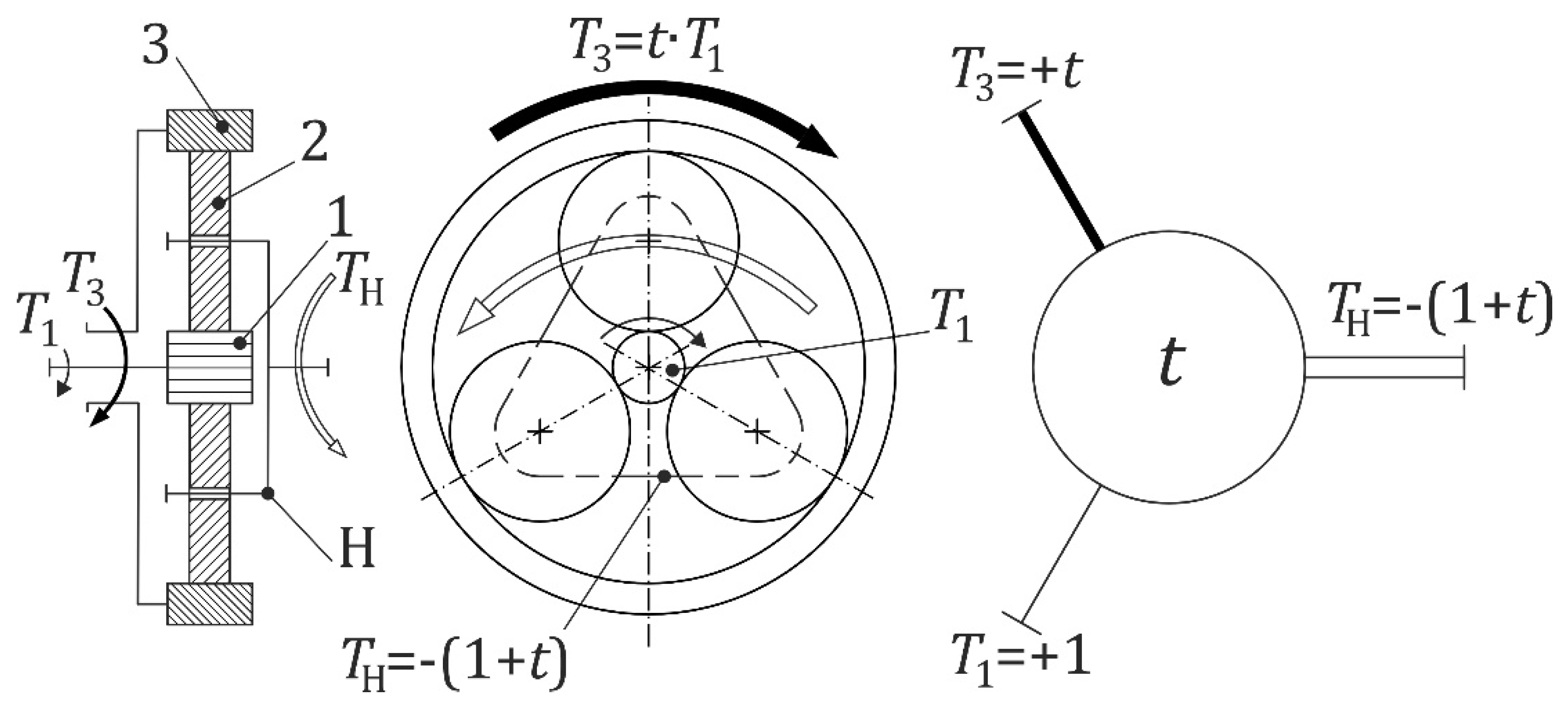
Figure 2.
Two-carrier train with labelled shafts.
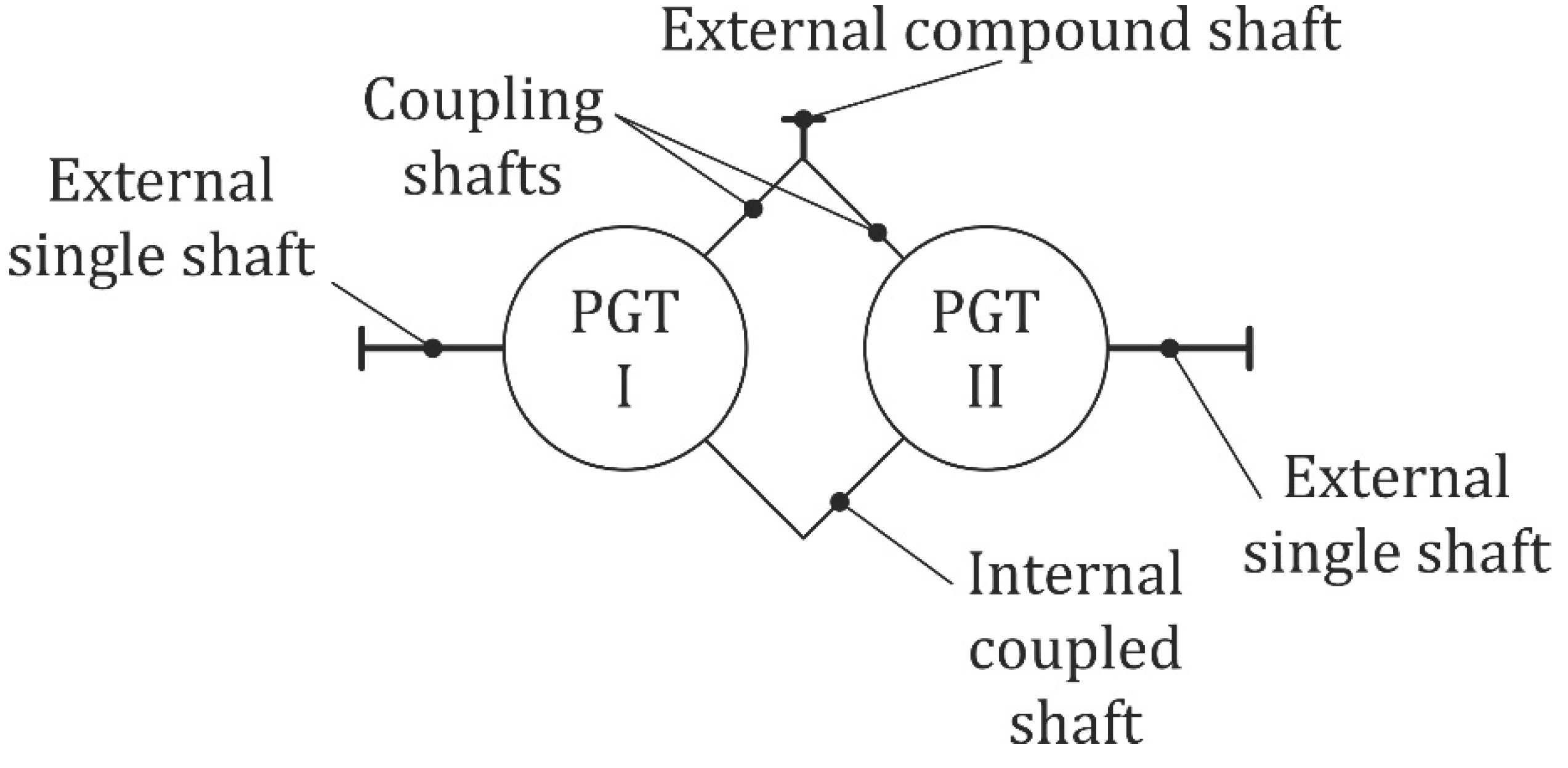
Figure 3.
Actual two-carrier train with labelled shaft torques and efficiencies [33].
Figure 3.
Actual two-carrier train with labelled shaft torques and efficiencies [33].
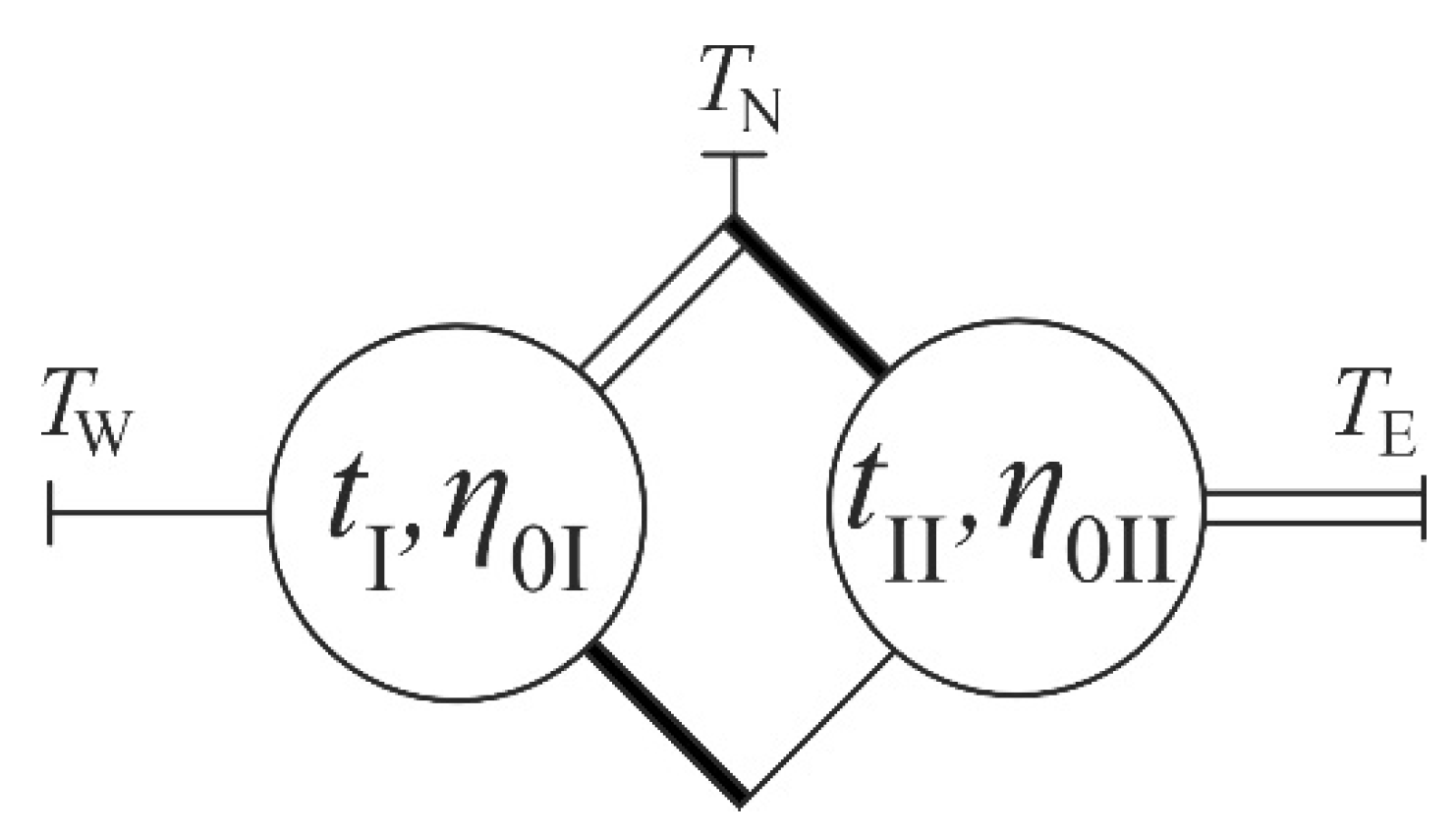
Figure 4.
Overview of two-carrier gear trains with three external shafts [34].
Figure 4.
Overview of two-carrier gear trains with three external shafts [34].
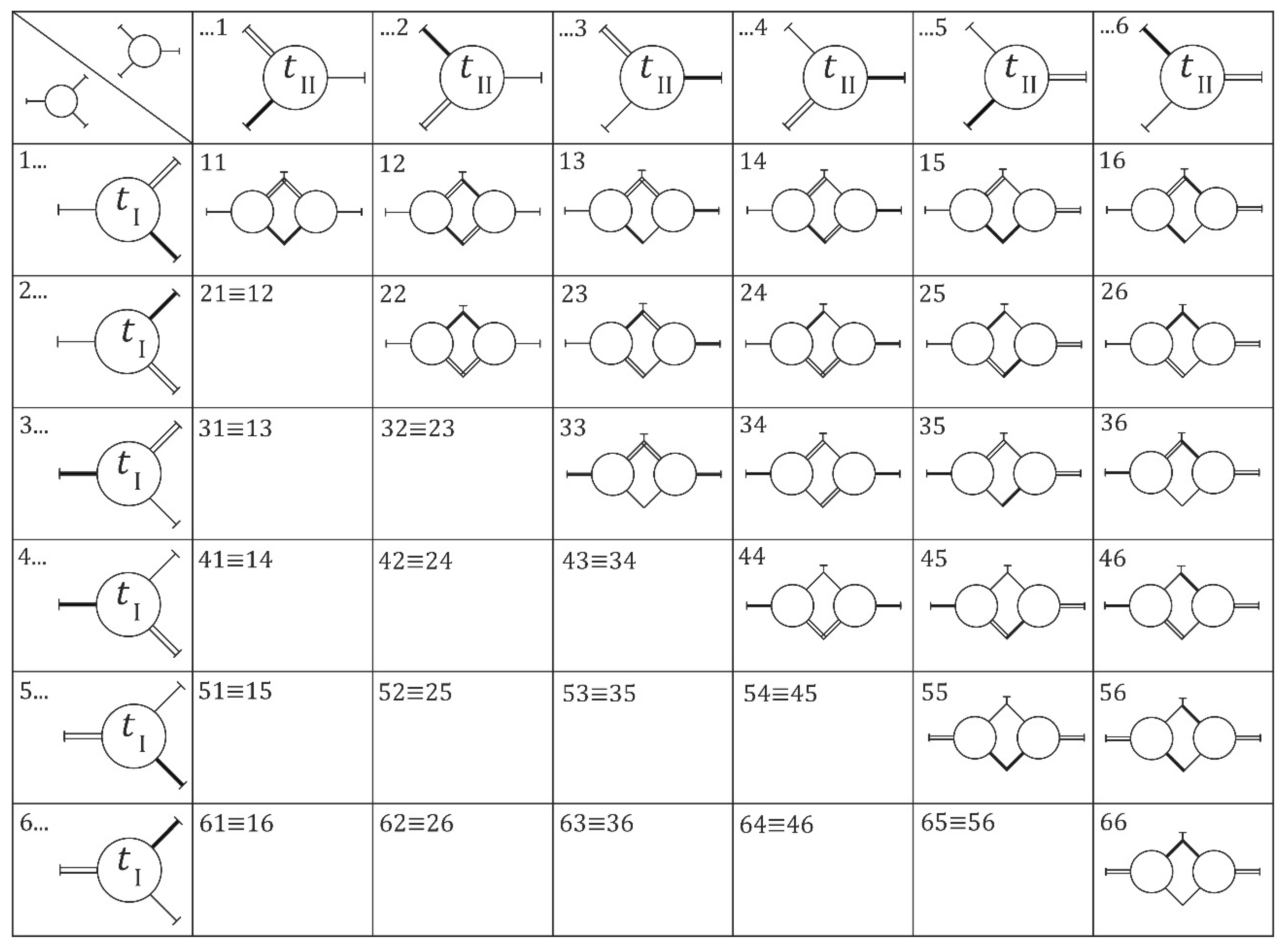
Figure 5.
Torque method analysis of S55NE(W) PGT acting as a reducer.
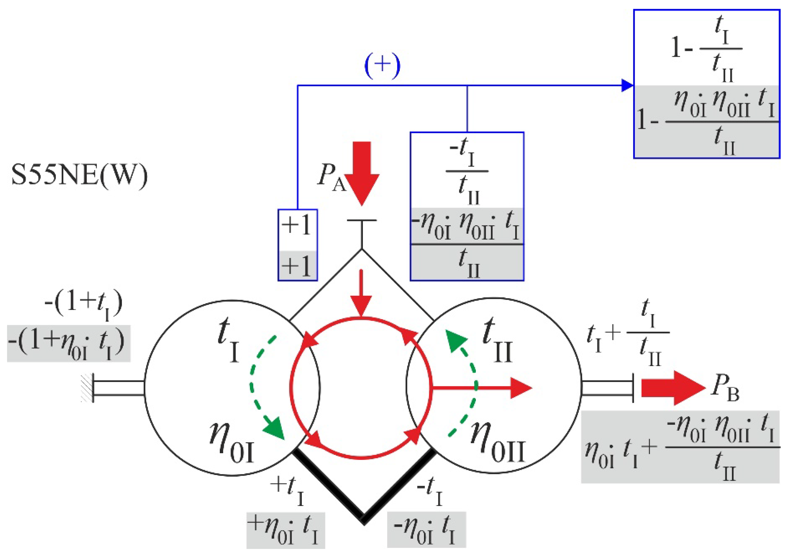
Figure 6.
Program operating schematic.
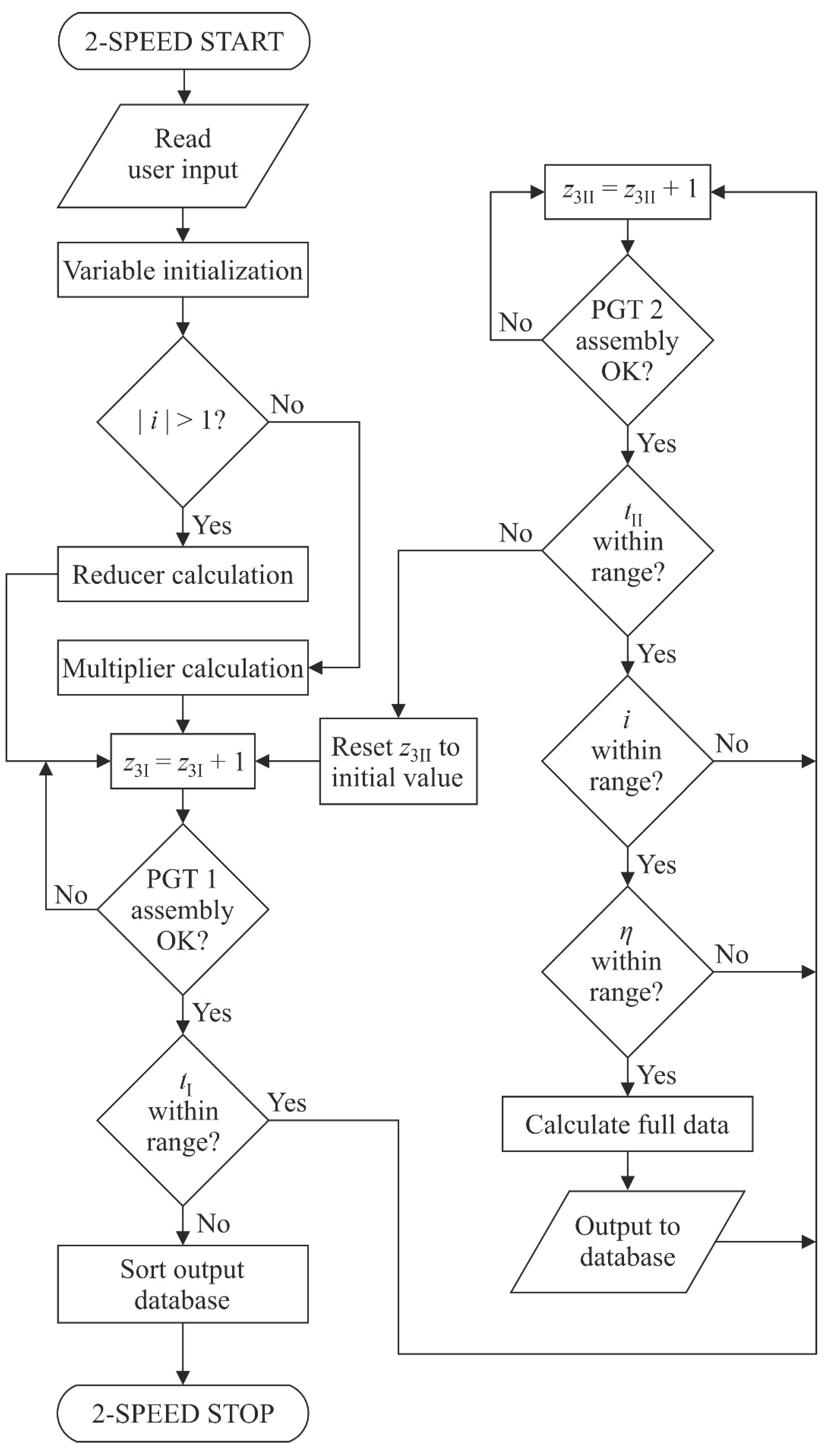
Figure 7.
(a) Relationship of the mass of the S26EW(N) gearset to the ideal torque ratios tI and tII for i = 0,02; (b) Relationship of the mass of the S26NW(E) gearset to the ideal torque ratios tI and tII for i = - 0,02.
Figure 7.
(a) Relationship of the mass of the S26EW(N) gearset to the ideal torque ratios tI and tII for i = 0,02; (b) Relationship of the mass of the S26NW(E) gearset to the ideal torque ratios tI and tII for i = - 0,02.
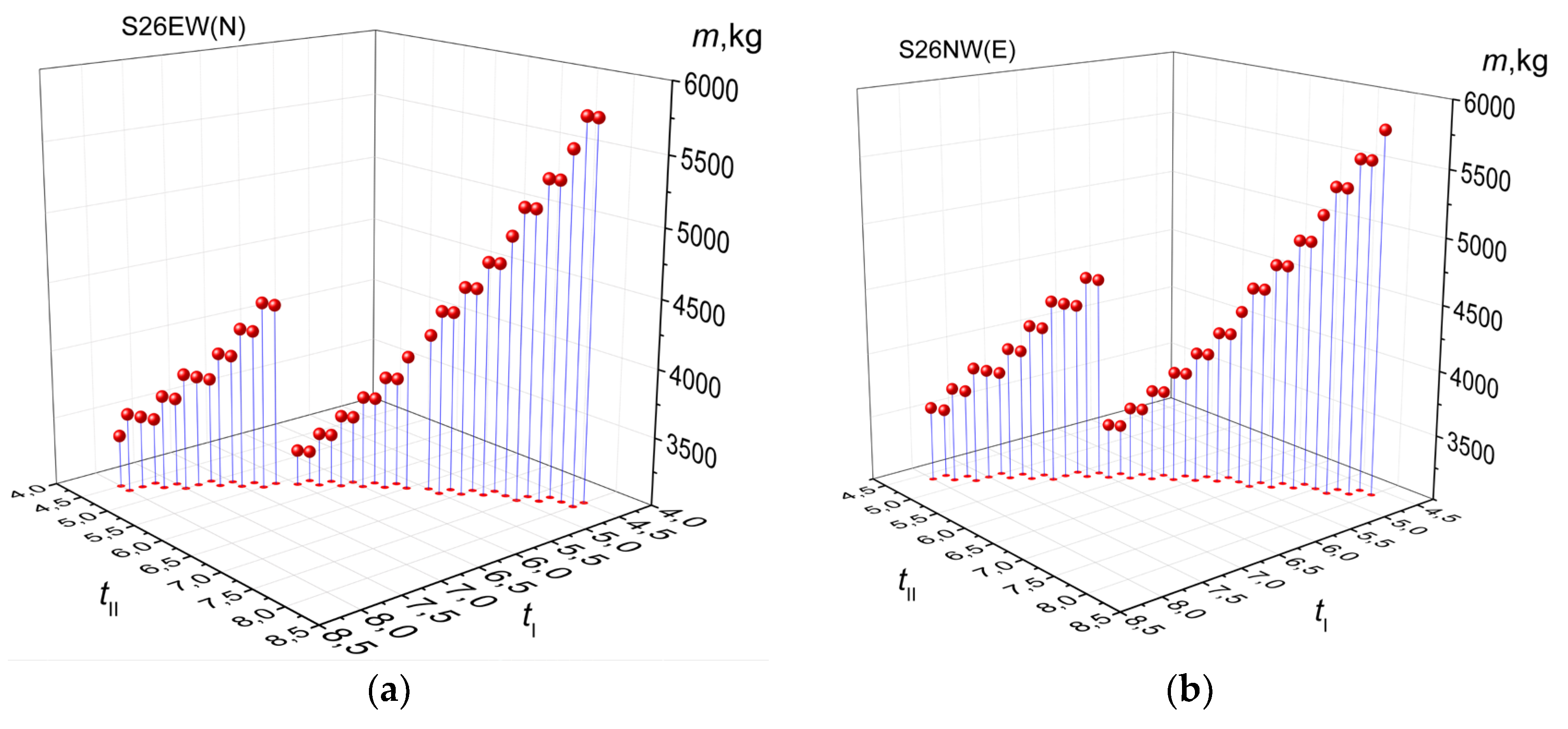
Figure 8.
(a) Relationship of the minimal largest ring gear reference diameter of the S26EW(N) gearset to the ideal torque ratios tI and tII for i = 0,02; (b) Relationship of the minimal largest ring gear reference diameter of the S26NW(E) gearset to the ideal torque ratios tI and tII for i = - 0,02.
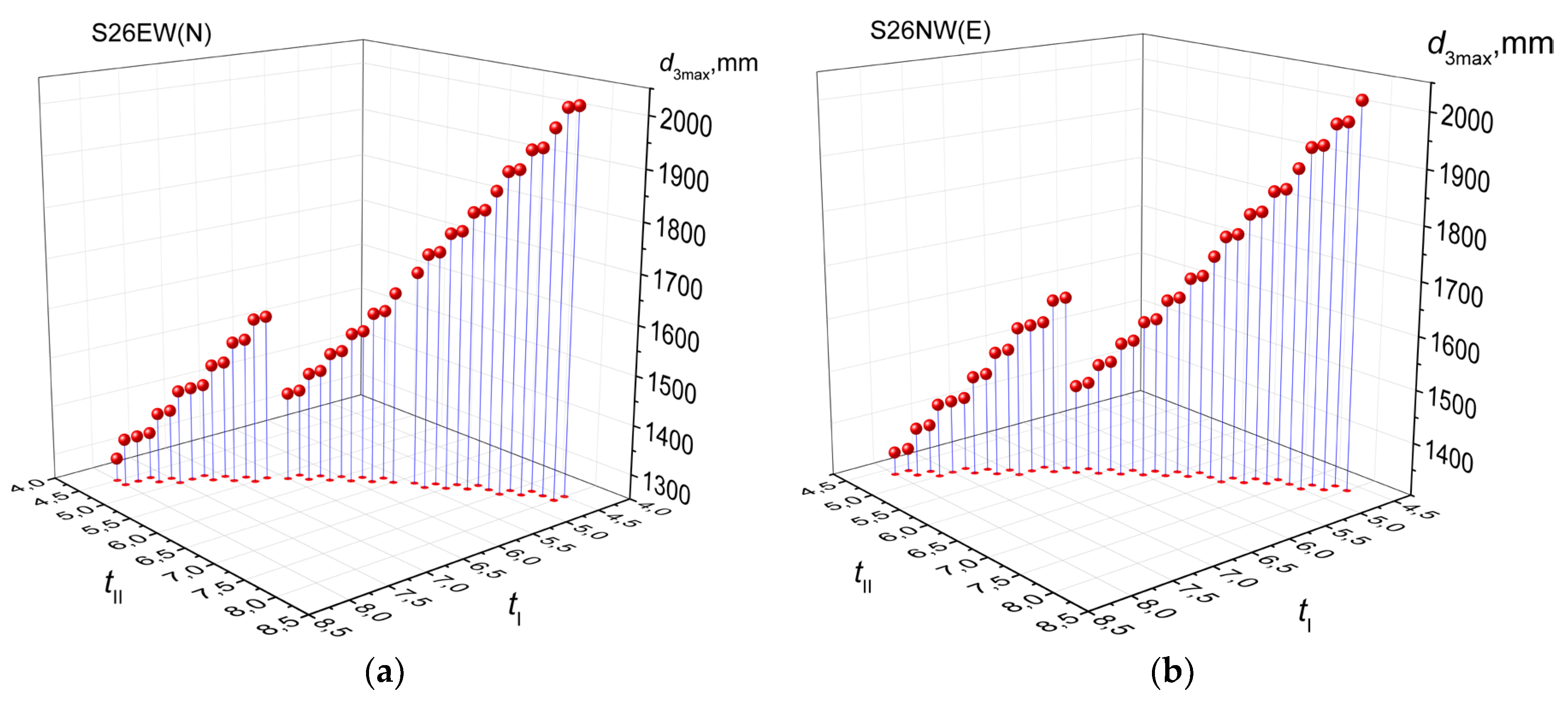
Figure 9.
(a) Relationship of the efficiency of the S16NW(E) gearset to the ideal torque ratios tI and tII for i = 0,02; (b) Relationship of the efficiency of the S16EW(N) gearset to the ideal torque ratios tI and tII for i = - 0,02.
Figure 9.
(a) Relationship of the efficiency of the S16NW(E) gearset to the ideal torque ratios tI and tII for i = 0,02; (b) Relationship of the efficiency of the S16EW(N) gearset to the ideal torque ratios tI and tII for i = - 0,02.

Figure 10.
(a) Relationship of the mass of the S16NW(E) gearset to the ideal torque ratios tI and tII for i = 0,08; (b) Relationship of the mass of the S26NE(W) gearset to the ideal torque ratios tI and tII for i = - 0,08.
Figure 10.
(a) Relationship of the mass of the S16NW(E) gearset to the ideal torque ratios tI and tII for i = 0,08; (b) Relationship of the mass of the S26NE(W) gearset to the ideal torque ratios tI and tII for i = - 0,08.
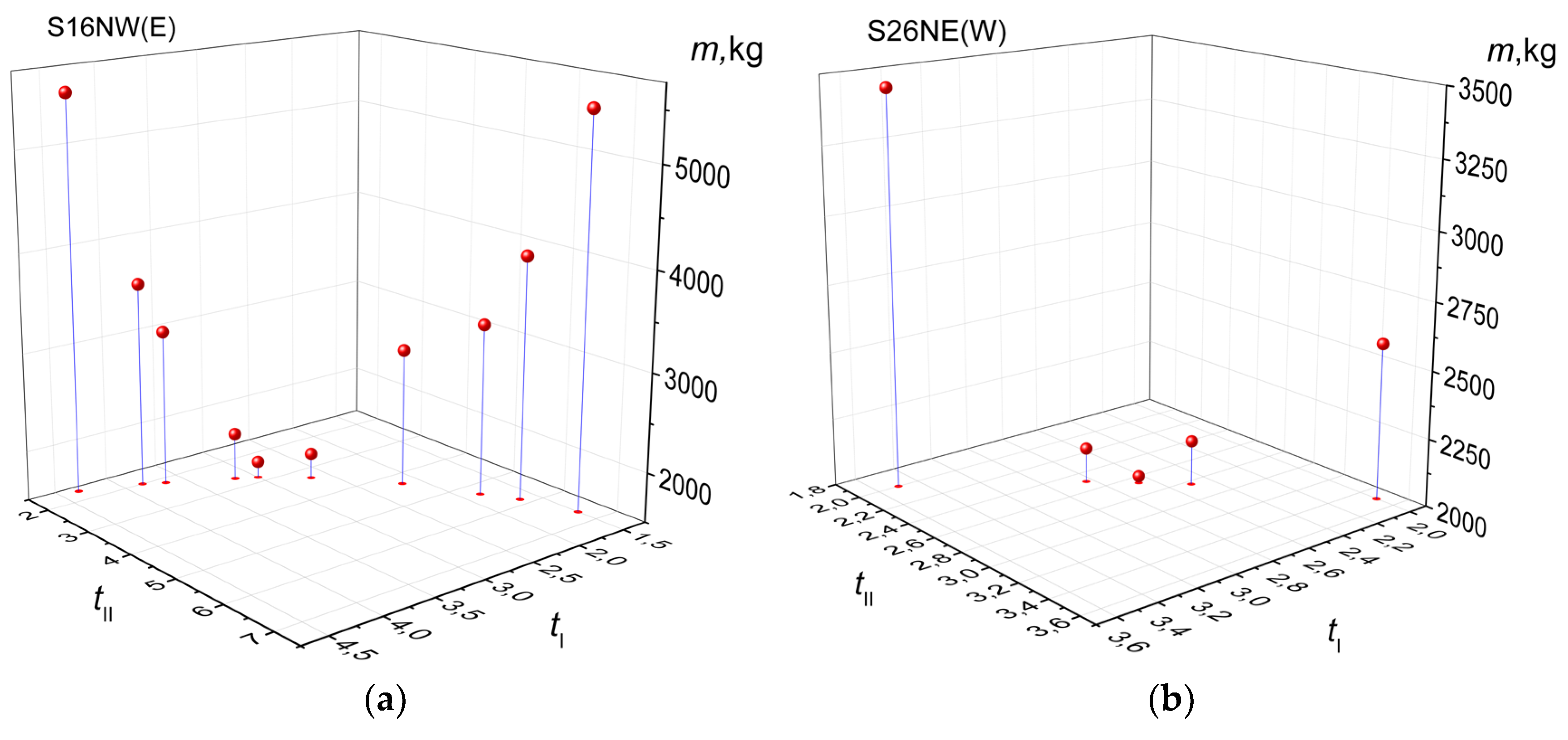
Figure 11.
(a) Relationship of the minimal largest ring gear reference diameter of the S16NW(E) gearset to the ideal torque ratios tI and tII for i = 0,08; (b) Relationship of the minimal largest ring gear reference diameter of the S26NE(W) gearset to the ideal torque ratios tI and tII for i = - 0,08.
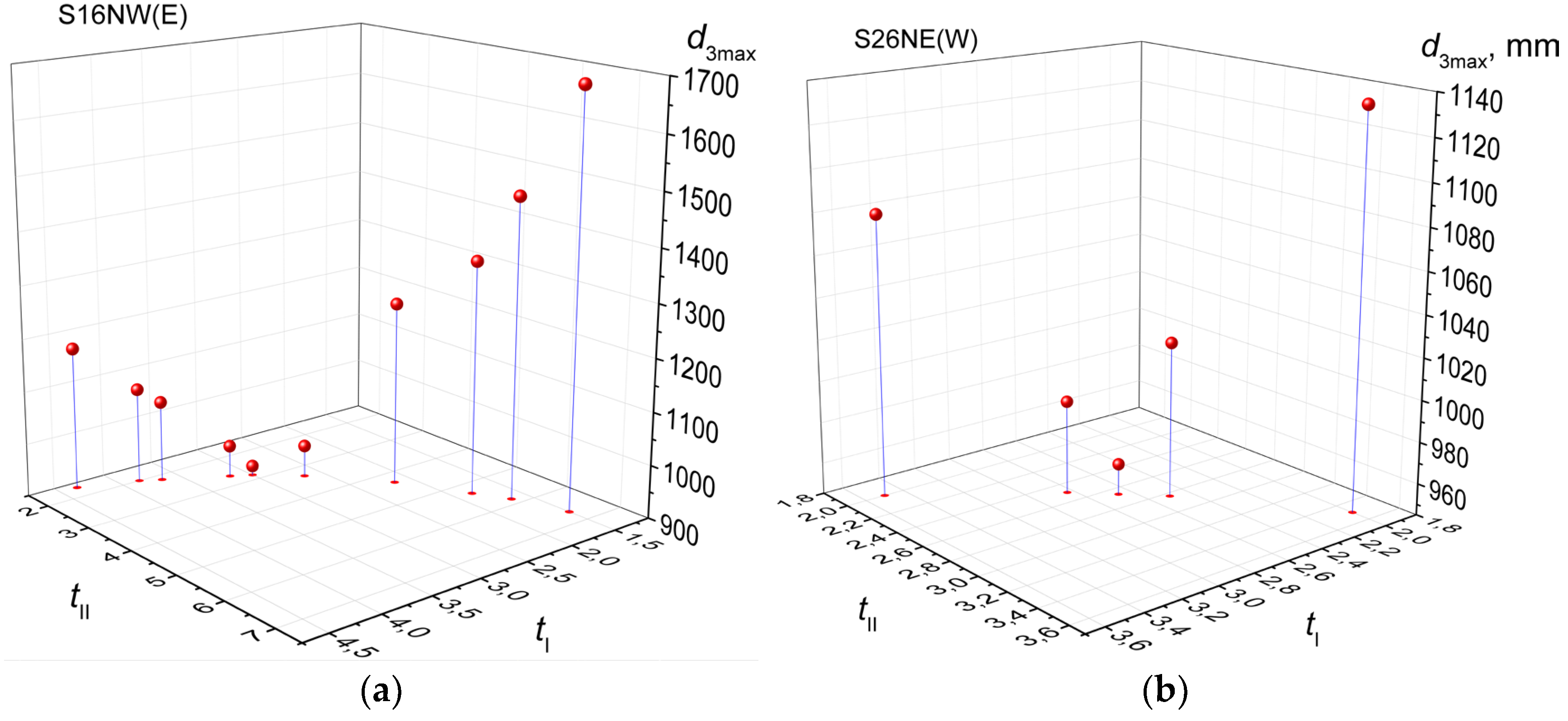
Figure 12.
(a) Relationship of the efficiency of the S16NW(E) gearset to the ideal torque ratios tI and tII for i = 0,08; (b) Relationship of the mass of the S26NW(E) gearset to the ideal torque ratios tI and tII for i = - 0,08.
Figure 12.
(a) Relationship of the efficiency of the S16NW(E) gearset to the ideal torque ratios tI and tII for i = 0,08; (b) Relationship of the mass of the S26NW(E) gearset to the ideal torque ratios tI and tII for i = - 0,08.
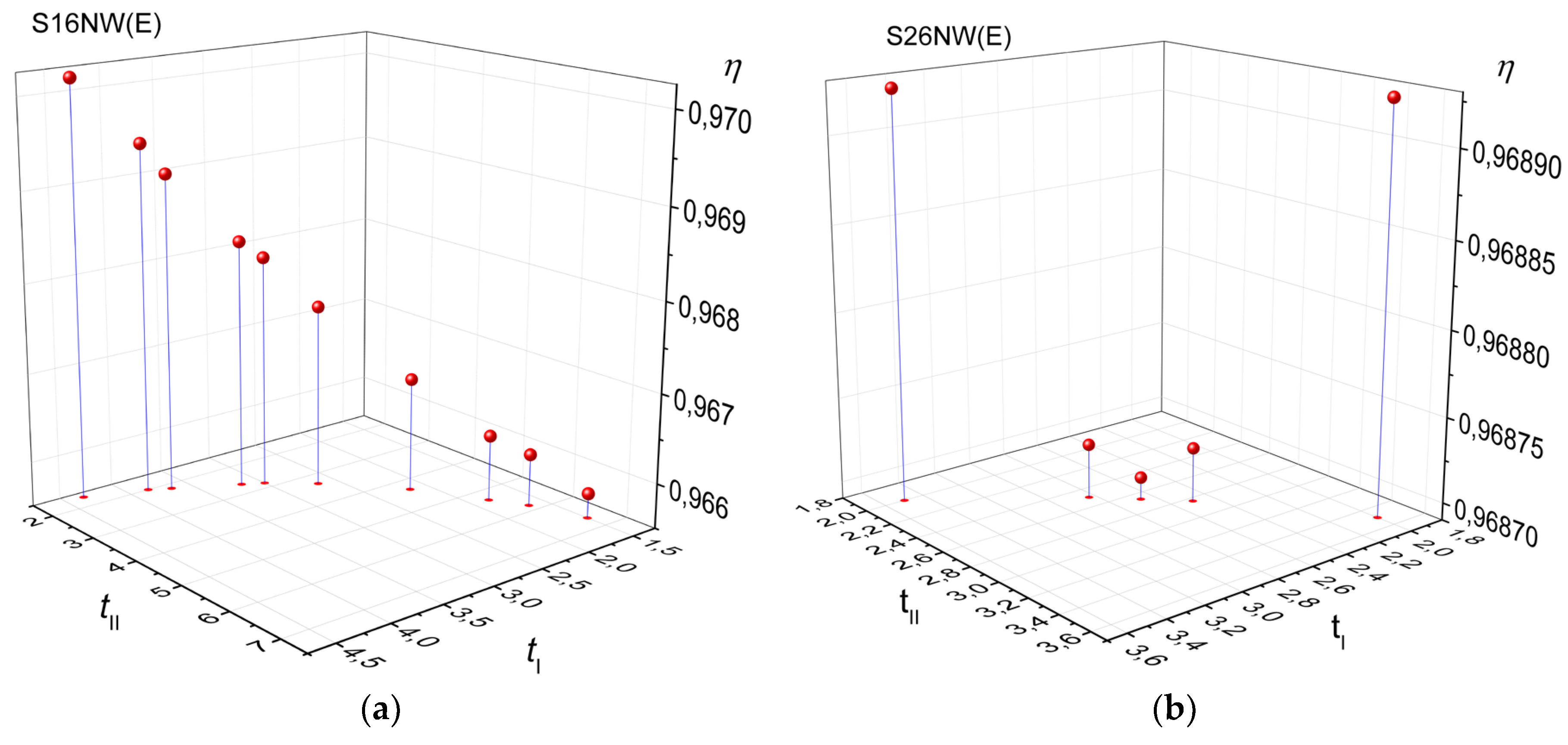
Figure 13.
Schematic representation of the five best gear train solutions.
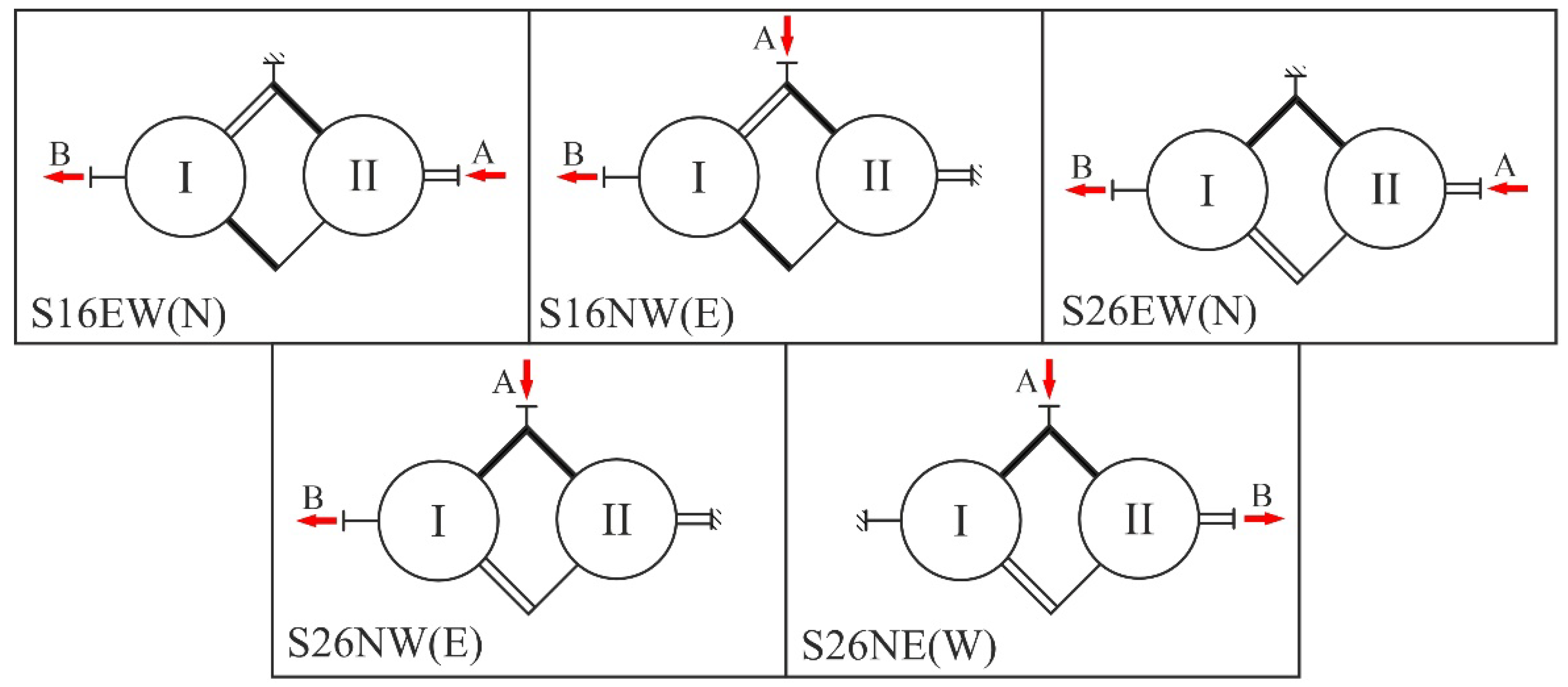
Figure 14.
Kinematic schemes of the five best gear train solutions.
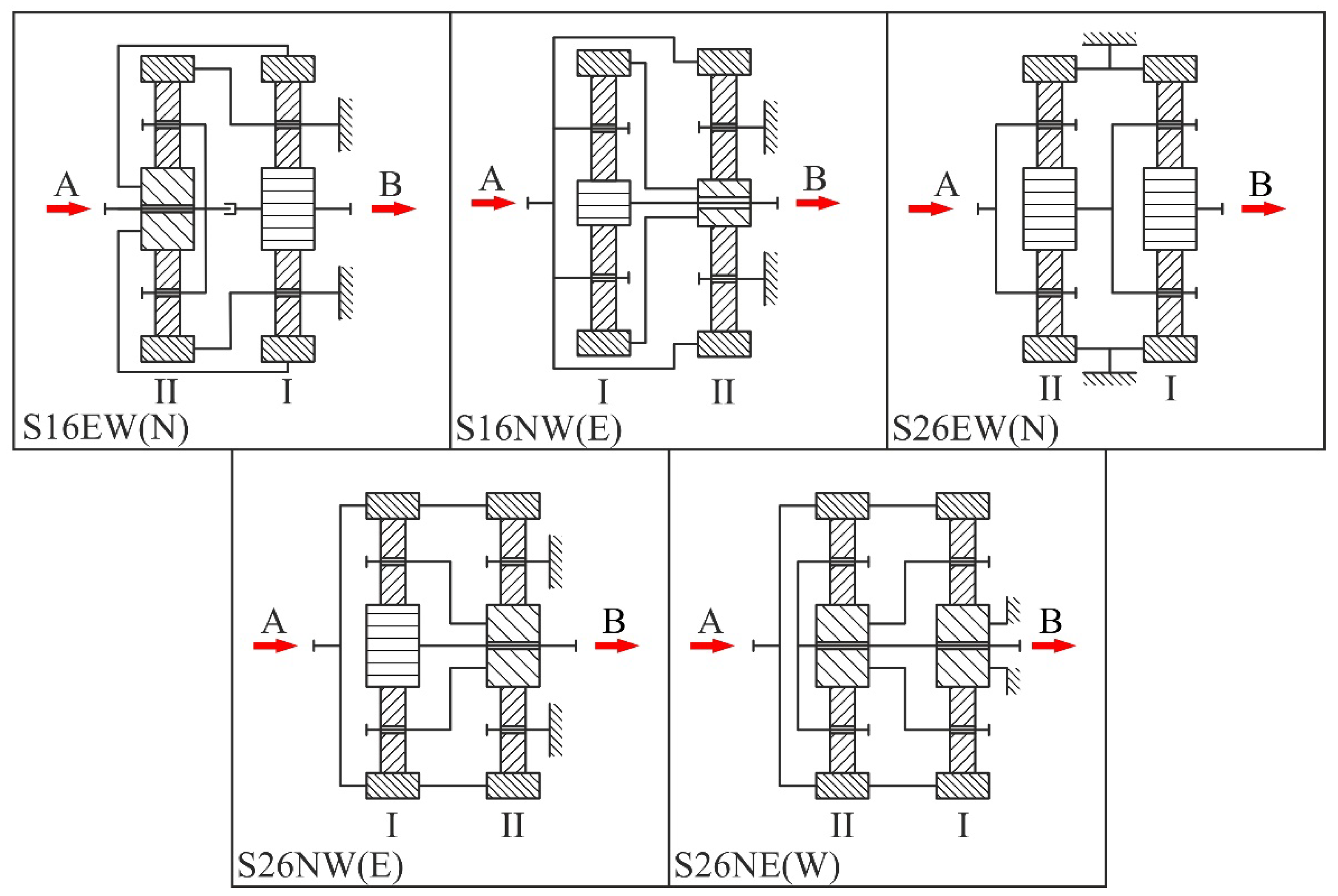
Figure 15.
Kinematic scheme of the three-carrier gear train solution.
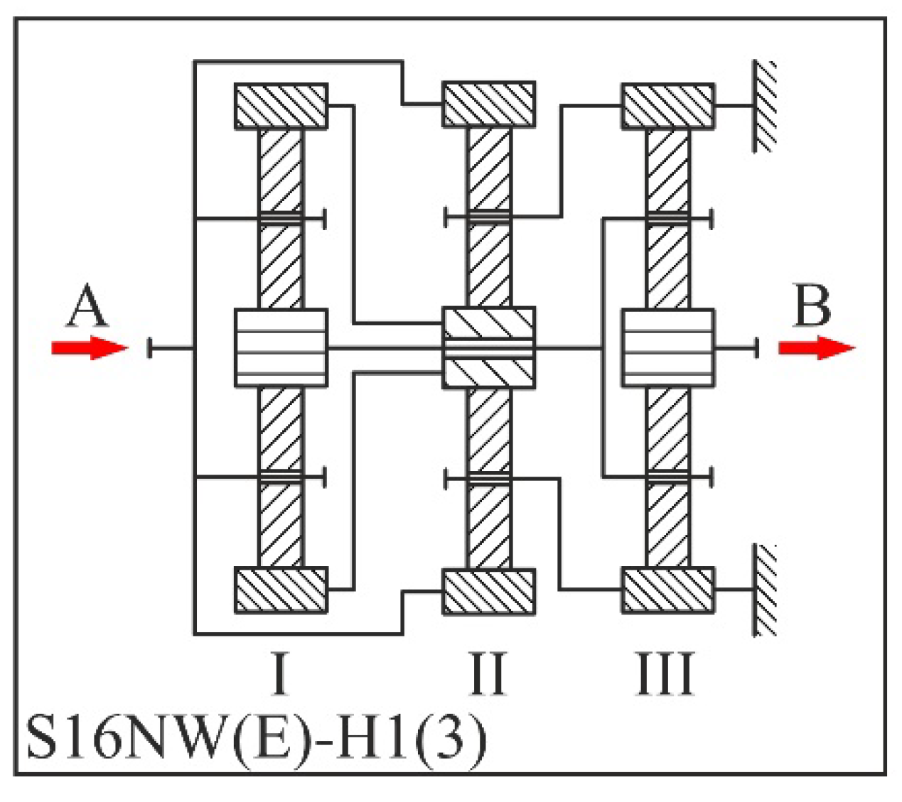

Table 1.
Gear trains with nominal i = 0,02 ranked according to minimal mass.
| No. | S/V | tI | tII | i | m, kg | η | d3max, mm | d3max / d3min | mI, mm | mII, mm |
|---|---|---|---|---|---|---|---|---|---|---|
| 1 | S26EW(N) | 6,3333 | 5,6667 | 0,02045 | 3223,518 | 0,96592 | 1428 | 1,56579 | 8 | 14 |
| 2 | S16NW(E) | 7,3333 | 5,6667 | 0,02004 | 3450,693 | 0,964 | 1428 | 1,35227 | 8 | 14 |
| 3 | S55EN(W) | 2,5 | 2,3333 | 0,02 | 4002,031 | 0,41679 | 1050 | 1,06061 | 22 | 25 |
| 4 | S55WN(E) | 2,3333 | 2,5 | 0,02 | 4002,031 | 0,41679 | 1050 | 1,06061 | 25 | 22 |
| 5 | S23NW(E) | 6,5 | 6,5 | 0,0201 | 4151,259 | 0,96369 | 1638 | 1,75 | 8 | 14 |
| 6 | S13EW(N) | 7,3333 | 6,6667 | 0,02045 | 4537,879 | 0,9604 | 1680 | 1,59091 | 8 | 14 |
| 7 | S44WN(E) | 2,5 | 2,3333 | 0,02 | 5406,571 | 0,41679 | 1134 | 1,008 | 25 | 27 |
| 8 | S44EN(W) | 2,3333 | 2,5 | 0,02 | 5406,571 | 0,41679 | 1134 | 1,008 | 27 | 25 |
| 9 | S66WN(E) | 7,1667 | 7 | 0,02041 | 8409,254 | 0 | 1806 | 1,02381 | 14 | 14 |
| 10 | S66EN(W) | 7 | 7,1667 | 0,02041 | 8409,254 | 0 | 1806 | 1,02381 | 14 | 14 |
| 11 | S22EN(W) | 7,1667 | 7 | 0,02041 | 60320,46 | 0 | 3483 | 1,02381 | 27 | 27 |
| 12 | S22WN(E) | 7 | 7,1667 | 0,02041 | 60320,46 | 0 | 3483 | 1,02381 | 27 | 27 |
Table 2.
Gear trains with nominal i = -0,02 ranked according to minimal mass.
| No. | S/V | tI | tII | i | m, kg | η | d3max, mm | d3max / d3min | mI, mm | mII, mm |
|---|---|---|---|---|---|---|---|---|---|---|
| 1 | S26NW(E) | 6,3333 | 5,8333 | -0,02036 | 3391,139 | 0,96518 | 1470 | 1,61184 | 8 | 14 |
| 2 | S16EW(N) | 7,3333 | 5,6667 | -0,02045 | 3450,693 | 0,96329 | 1428 | 1,35227 | 8 | 14 |
| 3 | S55EN(W) | 3,5 | 3,8333 | -0,0197 | 3630,646 | 0,55338 | 1134 | 1,02717 | 18 | 16 |
| 4 | S55WN(E) | 3,8333 | 3,5 | -0,0197 | 3630,646 | 0,55338 | 1134 | 1,02717 | 16 | 18 |
| 5 | S23EW(N) | 6,3333 | 6,6667 | -0,02045 | 4310,703 | 0,96303 | 1680 | 1,84211 | 8 | 14 |
| 6 | S44EN(W) | 3,8333 | 3,5 | -0,0197 | 4339,631 | 0,55338 | 1242 | 1,09524 | 18 | 18 |
| 7 | S44WN(E) | 3,5 | 3,8333 | -0,0197 | 4339,631 | 0,55338 | 1242 | 1,09524 | 18 | 18 |
| 8 | S13NW(E) | 7,3333 | 6,8333 | -0,02036 | 4738,083 | 0,95963 | 1722 | 1,63068 | 8 | 14 |
| 9 | S66WN(E) | 7,1667 | 7,3333 | -0,02041 | 8836,816 | 0 | 1848 | 1,02326 | 14 | 14 |
| 10 | S66EN(W) | 7,3333 | 7,1667 | -0,02041 | 8836,816 | 0 | 1848 | 1,02326 | 14 | 14 |
| 11 | S22EN(W) | 7,1667 | 7,3333 | -0,02041 | 63387,41 | 0 | 3564 | 1,02326 | 27 | 27 |
| 12 | S22WN(E) | 7,3333 | 7,1667 | -0,02041 | 63387,41 | 0 | 3564 | 1,02326 | 27 | 27 |
Table 3.
Gear trains with nominal i = 0,02 ranked according to minimal larger ring gear reference diameter.
Table 3.
Gear trains with nominal i = 0,02 ranked according to minimal larger ring gear reference diameter.
| No. | S/V | tI | tII | i | m, kg | η | d3max, mm | d3max / d3min | mI, mm | mII, mm |
|---|---|---|---|---|---|---|---|---|---|---|
| 1 | S55EN(W) | 2,5 | 2,3333 | 0,02 | 4002,031 | 0,41679 | 1050 | 1,06061 | 22 | 25 |
| 2 | S55WN(E) | 2,3333 | 2,5 | 0,02 | 4002,031 | 0,41679 | 1050 | 1,06061 | 25 | 22 |
| 3 | S44EN(W) | 2,3333 | 2,5 | 0,02 | 5406,571 | 0,41679 | 1134 | 1,008 | 27 | 25 |
| 4 | S44WN(E) | 2,5 | 2,3333 | 0,02 | 5406,571 | 0,41679 | 1134 | 1,008 | 25 | 27 |
| 5 | S26EW(N) | 8 | 4,5 | 0,0202 | 3381,955 | 0,96605 | 1296 | 1,125 | 8 | 16 |
| 6 | S16NW(E) | 7,3333 | 5,6667 | 0,02004 | 3450,693 | 0,964 | 1428 | 1,35227 | 8 | 14 |
| 7 | S23NW(E) | 8 | 5,3333 | 0,02041 | 4430,348 | 0,96328 | 1536 | 1,33333 | 8 | 16 |
| 8 | S13EW(N) | 7,3333 | 6,6667 | 0,02045 | 4537,879 | 0,9604 | 1680 | 1,59091 | 8 | 14 |
| 9 | S66WN(E) | 7,1667 | 7 | 0,02041 | 8409,254 | 0 | 1806 | 1,02381 | 14 | 14 |
| 10 | S66EN(W) | 7 | 7,1667 | 0,02041 | 8409,254 | 0 | 1806 | 1,02381 | 14 | 14 |
| 11 | S22EN(W) | 7,1667 | 7 | 0,02041 | 60320,46 | 0 | 3483 | 1,02381 | 27 | 27 |
| 12 | S22WN(E) | 7 | 7,1667 | 0,02041 | 60320,46 | 0 | 3483 | 1,02381 | 27 | 27 |
Table 4.
Gear trains with nominal i = -0,02 ranked according to minimal larger ring gear reference diameter.
Table 4.
Gear trains with nominal i = -0,02 ranked according to minimal larger ring gear reference diameter.
| No. | S/V | tI | tII | i | m, kg | η | d3max, mm | d3max / d3min | mI, mm | mII, mm |
|---|---|---|---|---|---|---|---|---|---|---|
| 1 | S55EN(W) | 2,3333 | 2,5 | -0,02041 | 4002,031 | 0,41188 | 1050 | 1,06061 | 25 | 22 |
| 2 | S55WN(E) | 2,5 | 2,3333 | -0,02041 | 4002,031 | 0,41188 | 1050 | 1,06061 | 22 | 25 |
| 3 | S44EN(W) | 2,5 | 2,3333 | -0,02041 | 5406,571 | 0,41188 | 1134 | 1,008 | 25 | 27 |
| 4 | S44WN(E) | 2,3333 | 2,5 | -0,02041 | 5406,571 | 0,41188 | 1134 | 1,008 | 27 | 25 |
| 5 | S26NW(E) | 7,8333 | 4,6667 | -0,02039 | 3530,972 | 0,96532 | 1344 | 1,19149 | 8 | 16 |
| 6 | S16EW(N) | 7,3333 | 5,6667 | -0,02045 | 3450,693 | 0,96329 | 1428 | 1,35227 | 8 | 14 |
| 7 | S23EW(N) | 8 | 5,5 | -0,0202 | 4664,346 | 0,96254 | 1584 | 1,375 | 8 | 16 |
| 8 | S13NW(E) | 7,3333 | 6,8333 | -0,02036 | 4738,083 | 0,95963 | 1722 | 1,63068 | 8 | 14 |
| 9 | S66WN(E) | 7,1667 | 7,3333 | -0,02041 | 8836,816 | 0 | 1848 | 1,02326 | 14 | 14 |
| 10 | S66EN(W) | 7,3333 | 7,1667 | -0,02041 | 8836,816 | 0 | 1848 | 1,02326 | 14 | 14 |
| 11 | S22EN(W) | 7,1667 | 7,3333 | -0,02041 | 63387,41 | 0 | 3564 | 1,02326 | 27 | 27 |
| 12 | S22WN(E) | 7,3333 | 7,1667 | -0,02041 | 63387,41 | 0 | 3564 | 1,02326 | 27 | 27 |
Table 5.
Gear trains with nominal i = 0,02 ranked according to maximum efficiency.
| No. | S/V | tI | tII | i | m, kg | η | d3max, mm | d3max / d3min | mI, mm | mII, mm |
|---|---|---|---|---|---|---|---|---|---|---|
| 1 | S26EW(N) | 4,5 | 8 | 0,0202 | 5742,648 | 0,96605 | 2016 | 3,11111 | 8 | 14 |
| 2 | S16NW(E) | 8 | 5 | 0,02041 | 3986,672 | 0,96433 | 1440 | 1,25 | 8 | 16 |
| 3 | S23NW(E) | 5 | 8 | 0,02041 | 5818,238 | 0,96433 | 2016 | 2,8 | 8 | 14 |
| 4 | S13EW(N) | 6,1667 | 8 | 0,02027 | 6030,078 | 0,9604 | 2016 | 2,27027 | 8 | 14 |
| 5 | S55WN(E) | 6,5 | 7,6667 | 0,02029 | 8474,421 | 0,75689 | 1932 | 1,17949 | 14 | 14 |
| 6 | S55EN(W) | 7,6667 | 6,5 | 0,02029 | 8474,421 | 0,75689 | 1932 | 1,17949 | 14 | 14 |
| 7 | S44WN(E) | 7,6667 | 6,5 | 0,02029 | 10198,16 | 0,75689 | 1932 | 1,03205 | 14 | 16 |
| 8 | S44EN(W) | 6,5 | 7,6667 | 0,02029 | 10198,16 | 0,75689 | 1932 | 1,03205 | 16 | 14 |
| 9 | S66WN(E) | 7,1667 | 7 | 0,02041 | 8409,254 | 0 | 1806 | 1,02381 | 14 | 14 |
| 10 | S22EN(W) | 7,1667 | 7 | 0,02041 | 60320,46 | 0 | 3483 | 1,02381 | 27 | 27 |
| 11 | S66EN(W) | 7 | 7,1667 | 0,02041 | 8409,254 | 0 | 1806 | 1,02381 | 14 | 14 |
| 12 | S22WN(E) | 7 | 7,1667 | 0,02041 | 60320,46 | 0 | 3483 | 1,02381 | 27 | 27 |
Table 6.
Gear trains with nominal i = -0,02 ranked according to maximum efficiency.
| No. | S/V | tI | tII | i | m, kg | η | d3max, mm | d3max / d3min | mI, mm | mII, mm |
|---|---|---|---|---|---|---|---|---|---|---|
| 1 | S26NW(E) | 4,6667 | 7,8333 | -0,02039 | 5528,613 | 0,96532 | 1974 | 2,9375 | 8 | 14 |
| 2 | S16EW(N) | 8 | 5,1667 | -0,02027 | 4204,457 | 0,96352 | 1488 | 1,29167 | 8 | 16 |
| 3 | S23EW(N) | 5,1667 | 8 | -0,02027 | 5845,461 | 0,96352 | 2016 | 2,70968 | 8 | 14 |
| 4 | S13NW(E) | 6,5 | 8 | -0,01961 | 6099,724 | 0,95965 | 2016 | 2,15385 | 8 | 14 |
| 5 | S55WN(E) | 7,8333 | 6,6667 | -0,01981 | 8901,982 | 0,74737 | 1974 | 1,175 | 14 | 14 |
| 6 | S55EN(W) | 6,6667 | 7,8333 | -0,01981 | 8901,982 | 0,74737 | 1974 | 1,175 | 14 | 14 |
| 7 | S44WN(E) | 6,6667 | 7,8333 | -0,01981 | 8901,982 | 0,74737 | 1974 | 1,175 | 14 | 14 |
| 8 | S44EN(W) | 7,8333 | 6,6667 | -0,01981 | 8901,982 | 0,74737 | 1974 | 1,175 | 14 | 14 |
| 9 | S66WN(E) | 7,1667 | 7,3333 | -0,02041 | 8836,816 | 0 | 1848 | 1,02326 | 14 | 14 |
| 10 | S22EN(W) | 7,1667 | 7,3333 | -0,02041 | 63387,41 | 0 | 3564 | 1,02326 | 27 | 27 |
| 11 | S66EN(W) | 7,3333 | 7,1667 | -0,02041 | 8836,816 | 0 | 1848 | 1,02326 | 14 | 14 |
| 12 | S22WN(E) | 7,3333 | 7,1667 | -0,02041 | 63387,41 | 0 | 3564 | 1,02326 | 27 | 27 |
Table 7.
Gear trains with nominal i = 0,08 ranked according to minimal mass.
| No. | S/V | tI | tII | i | m, kg | η | d3max, mm | d3max / d3min | mI, mm | mII, mm |
|---|---|---|---|---|---|---|---|---|---|---|
| 1 | S16NW(E) | 3 | 2,8333 | 0,08 | 1665,727 | 0,96811 | 918 | 1,41667 | 12 | 18 |
| 2 | S23NW(E) | 2,8333 | 3 | 0,08 | 1778,35 | 0,96811 | 972 | 1,58824 | 12 | 18 |
| 3 | S26EW(N) | 2 | 3,1667 | 0,08 | 2201,356 | 0,97151 | 1026 | 1,58333 | 18 | 18 |
| 4 | S13EW(N) | 4,1667 | 3 | 0,08 | 2777,048 | 0,9604 | 1080 | 1,2 | 12 | 20 |
| 5 | S66WN(E) | 3,1667 | 2,8333 | 0,08 | 2828,445 | 0,64636 | 1026 | 1,11765 | 18 | 18 |
| 6 | S55WN(E) | 3,5 | 5,5 | 0,08081 | 3818,928 | 0,91335 | 1386 | 1,375 | 16 | 14 |
| 7 | S46EW(N) | 1,6667 | 6,8333 | 0,07979 | 4512,495 | 0,97505 | 1722 | 2,87 | 20 | 14 |
| 8 | S34NE(W) | 6,8333 | 1,5 | 0,08072 | 5188,004 | 0,97426 | 1722 | 2,36214 | 14 | 27 |
| 9 | S33EN(W) | 3,8333 | 4,1667 | 0,08 | 5233,727 | 0,52582 | 1350 | 1,08696 | 18 | 18 |
| 10 | S44EN(W) | 3,5 | 5,5 | 0,08081 | 5605,839 | 0,91335 | 1584 | 1,39683 | 18 | 16 |
| 11 | S25EW(N) | 7 | 1,8333 | 0,08088 | 6825,57 | 0,97543 | 1512 | 1,27273 | 12 | 36 |
| 12 | S15NW(E) | 6,8333 | 1,5 | 0,08072 | 10673,07 | 0,97426 | 1476 | 1,09333 | 12 | 50 |
| 13 | S22WN(E) | 2,8333 | 3,1667 | 0,08 | 11112,29 | 0,64636 | 1539 | 1,00588 | 30 | 27 |
| 14 | S11WN(E) | 3,8333 | 4,1667 | 0,08 | 17663,83 | 0,52582 | 2025 | 1,08696 | 27 | 27 |
Table 8.
Gear trains with nominal i = -0,08 ranked according to minimal mass.
| No. | S/V | tI | tII | i | m, kg | η | d3max, mm | d3max / d3min | mI, mm | mII, mm |
|---|---|---|---|---|---|---|---|---|---|---|
| 1 | S16EW(N) | 3 | 3,1667 | -0,08 | 1997,356 | 0,96503 | 1026 | 1,58333 | 12 | 18 |
| 2 | S26NW(E) | 2,6667 | 2,6667 | -0,08036 | 2026,302 | 0,9687 | 960 | 1,42857 | 14 | 20 |
| 3 | S23EW(N) | 3,1667 | 3 | -0,08 | 2400,191 | 0,96503 | 1080 | 1,57895 | 12 | 20 |
| 4 | S13NW(E) | 3,8333 | 3,5 | -0,08054 | 2663,551 | 0,95735 | 1134 | 1,36957 | 12 | 18 |
| 5 | S55WN(E) | 3,6667 | 2,6667 | -0,08036 | 3028,666 | 0,86845 | 1056 | 1,1 | 16 | 20 |
| 6 | S66WN(E) | 3,1667 | 3,5 | -0,08 | 3537,87 | 0,58702 | 1134 | 1,10526 | 18 | 18 |
| 7 | S44EN(W) | 3,6667 | 2,6667 | -0,08036 | 4172,241 | 0,86845 | 1188 | 1,125 | 18 | 22 |
| 8 | S33WN(E) | 4,1667 | 4,5 | -0,08 | 6220,158 | 0,4654 | 1458 | 1,08 | 18 | 18 |
| 9 | S22WN(E) | 3,5 | 3,1667 | -0,08 | 11940,31 | 0,58702 | 1701 | 1,10526 | 27 | 27 |
| 10 | S11WN(E) | 4,5 | 4,1667 | -0,08 | 20993,04 | 0,4654 | 2187 | 1,08 | 27 | 27 |
Table 9.
Gear trains with nominal i = 0,08 ranked according to minimal larger ring gear reference diameter.
Table 9.
Gear trains with nominal i = 0,08 ranked according to minimal larger ring gear reference diameter.
| No. | S/V | tI | tII | i | m, kg | η | d3max, mm | d3max / d3min | mI, mm | mII, mm |
|---|---|---|---|---|---|---|---|---|---|---|
| 1 | S16NW(E) | 3 | 2,8333 | 0,08 | 1665,727 | 0,96811 | 918 | 1,41667 | 12 | 18 |
| 2 | S23NW(E) | 2,8333 | 3 | 0,08 | 1778,35 | 0,96811 | 972 | 1,58824 | 12 | 18 |
| 3 | S66EN(W) | 2,8333 | 3,1667 | 0,08 | 2828,445 | 0,64636 | 1026 | 1,11765 | 18 | 18 |
| 4 | S66WN(E) | 3,1667 | 2,8333 | 0,08 | 2828,445 | 0,64636 | 1026 | 1,11765 | 18 | 18 |
| 5 | S26EW(N) | 2 | 3,1667 | 0,08 | 2201,356 | 0,97151 | 1026 | 1,58333 | 18 | 18 |
| 6 | S13EW(N) | 4,6667 | 2,6667 | 0,08036 | 3087,809 | 0,9604 | 1056 | 1,04762 | 12 | 22 |
| 7 | S33WN(E) | 4,1667 | 3,8333 | 0,08 | 5233,727 | 0,52582 | 1350 | 1,08696 | 18 | 18 |
| 8 | S33EN(W) | 3,8333 | 4,1667 | 0,08 | 5233,727 | 0,52582 | 1350 | 1,08696 | 18 | 18 |
| 9 | S55WN(E) | 3,5 | 5,5 | 0,08081 | 3818,928 | 0,91335 | 1386 | 1,375 | 16 | 14 |
| 10 | S55EN(W) | 5,5 | 3,5 | 0,08081 | 3818,928 | 0,91335 | 1386 | 1,375 | 14 | 16 |
| 11 | S25EW(N) | 6,5 | 1,5 | 0,08 | 10424,34 | 0,97466 | 1404 | 1,04 | 12 | 50 |
| 12 | S15NW(E) | 6,8333 | 1,5 | 0,08072 | 10673,07 | 0,97426 | 1476 | 1,09333 | 12 | 50 |
| 13 | S22EN(W) | 3,1667 | 2,8333 | 0,08 | 11112,29 | 0,64636 | 1539 | 1,00588 | 27 | 30 |
| 14 | S22WN(E) | 2,8333 | 3,1667 | 0,08 | 11112,29 | 0,64636 | 1539 | 1,00588 | 30 | 27 |
| 15 | S44WN(E) | 5,5 | 3,5 | 0,08081 | 5605,839 | 0,91335 | 1584 | 1,39683 | 16 | 18 |
| 16 | S44EN(W) | 3,5 | 5,5 | 0,08081 | 5605,839 | 0,91335 | 1584 | 1,39683 | 18 | 16 |
| 17 | S46EW(N) | 1,5 | 6,5 | 0,08 | 4793,025 | 0,97466 | 1638 | 2,24691 | 27 | 14 |
| 18 | S34NE(W) | 6,8333 | 1,5 | 0,08072 | 5188,004 | 0,97426 | 1722 | 2,36214 | 14 | 27 |
| 19 | S11WN(E) | 3,8333 | 4,1667 | 0,08 | 17663,83 | 0,52582 | 2025 | 1,08696 | 27 | 27 |
| 20 | S11EN(W) | 4,1667 | 3,8333 | 0,08 | 17663,83 | 0,52582 | 2025 | 1,08696 | 27 | 27 |
Table 10.
Gear trains with nominal i = -0,08 ranked according to minimal larger ring gear reference diameter.
Table 10.
Gear trains with nominal i = -0,08 ranked according to minimal larger ring gear reference diameter.
| No. | S/V | tI | tII | i | m, kg | η | d3max, mm | d3max / d3min | mI, mm | mII, mm |
|---|---|---|---|---|---|---|---|---|---|---|
| 1 | S26NW(E) | 2,6667 | 2,6667 | -0,08036 | 2026,302 | 0,9687 | 960 | 1,42857 | 14 | 20 |
| 2 | S16EW(N) | 3 | 3,1667 | -0,08 | 1997,356 | 0,96503 | 1026 | 1,58333 | 12 | 18 |
| 3 | S55EN(W) | 2,1667 | 2,8333 | -0,08027 | 4154,823 | 0,84418 | 1053 | 1,03235 | 27 | 20 |
| 4 | S55WN(E) | 2,8333 | 2,1667 | -0,08027 | 4154,823 | 0,84418 | 1053 | 1,03235 | 20 | 27 |
| 5 | S23EW(N) | 3,6667 | 2,6667 | -0,08036 | 2649,395 | 0,96453 | 1056 | 1,33333 | 12 | 22 |
| 6 | S13NW(E) | 4,5 | 3 | -0,08 | 2930,026 | 0,95737 | 1080 | 1,11111 | 12 | 20 |
| 7 | S66EN(W) | 3,5 | 3,1667 | -0,08 | 3537,87 | 0,58702 | 1134 | 1,10526 | 18 | 18 |
| 8 | S66WN(E) | 3,1667 | 3,5 | -0,08 | 3537,87 | 0,58702 | 1134 | 1,10526 | 18 | 18 |
| 9 | S44WN(E) | 2,1667 | 2,8333 | -0,08027 | 5629,575 | 0,84418 | 1170 | 1,04278 | 30 | 22 |
| 10 | S44EN(W) | 2,8333 | 2,1667 | -0,08027 | 5629,575 | 0,84418 | 1170 | 1,04278 | 22 | 30 |
| 11 | S33WN(E) | 4,1667 | 4,5 | -0,08 | 6220,158 | 0,4654 | 1458 | 1,08 | 18 | 18 |
| 12 | S33EN(W) | 4,5 | 4,1667 | -0,08 | 6220,158 | 0,4654 | 1458 | 1,08 | 18 | 18 |
| 13 | S22EN(W) | 3,1667 | 3,5 | -0,08 | 11940,31 | 0,58702 | 1701 | 1,10526 | 27 | 27 |
| 14 | S22WN(E) | 3,5 | 3,1667 | -0,08 | 11940,31 | 0,58702 | 1701 | 1,10526 | 27 | 27 |
| 15 | S11EN(W) | 4,1667 | 4,5 | -0,08 | 20993,04 | 0,4654 | 2187 | 1,08 | 27 | 27 |
| 16 | S11WN(E) | 4,5 | 4,1667 | -0,08 | 20993,04 | 0,4654 | 2187 | 1,08 | 27 | 27 |
Table 11.
Gear trains with nominal i = 0,08 ranked according to maximum efficiency.
| No. | S/V | tI | tII | i | m, kg | η | d3max, mm | d3max / d3min | mI, mm | mII, mm |
|---|---|---|---|---|---|---|---|---|---|---|
| 1 | S25EW(N) | 7 | 1,8333 | 0,08088 | 6825,57 | 0,97543 | 1512 | 1,27273 | 12 | 36 |
| 2 | S46EW(N) | 1,8333 | 7 | 0,08088 | 4629,621 | 0,97543 | 1764 | 2,9697 | 18 | 14 |
| 3 | S34NE(W) | 6,8333 | 1,5 | 0,08072 | 5188,004 | 0,97426 | 1722 | 2,36214 | 14 | 27 |
| 4 | S15NW(E) | 6,8333 | 1,5 | 0,08072 | 10673,07 | 0,97426 | 1476 | 1,09333 | 12 | 50 |
| 5 | S26EW(N) | 1,5 | 4 | 0,08 | 3609,635 | 0,97203 | 1152 | 1,42222 | 30 | 16 |
| 6 | S23NW(E) | 1,6667 | 4,3333 | 0,07965 | 3389,309 | 0,97016 | 1248 | 1,664 | 25 | 16 |
| 7 | S16NW(E) | 4,3333 | 1,6667 | 0,07965 | 5509,867 | 0,97016 | 1170 | 1,25 | 12 | 39 |
| 8 | S13EW(N) | 2,5 | 5 | 0,08 | 3423,406 | 0,9604 | 1440 | 2,28571 | 14 | 16 |
| 9 | S55WN(E) | 4 | 6,6667 | 0,08 | 5527,108 | 0,92308 | 1680 | 1,45833 | 16 | 14 |
| 10 | S55EN(W) | 6,6667 | 4 | 0,08 | 5527,108 | 0,92308 | 1680 | 1,45833 | 14 | 16 |
| 11 | S44WN(E) | 6,6667 | 4 | 0,08 | 8124,056 | 0,92308 | 1920 | 1,48148 | 16 | 18 |
| 12 | S44EN(W) | 4 | 6,6667 | 0,08 | 8124,056 | 0,92308 | 1920 | 1,48148 | 18 | 16 |
| 13 | S22WN(E) | 2,8333 | 3,1667 | 0,08 | 11112,29 | 0,64636 | 1539 | 1,00588 | 30 | 27 |
| 14 | S66EN(W) | 2,8333 | 3,1667 | 0,08 | 2828,445 | 0,64636 | 1026 | 1,11765 | 18 | 18 |
| 15 | S66WN(E) | 3,1667 | 2,8333 | 0,08 | 2828,445 | 0,64636 | 1026 | 1,11765 | 18 | 18 |
| 16 | S22EN(W) | 3,1667 | 2,8333 | 0,08 | 11112,29 | 0,64636 | 1539 | 1,00588 | 27 | 30 |
| 17 | S11EN(W) | 4,1667 | 3,8333 | 0,08 | 17663,83 | 0,52582 | 2025 | 1,08696 | 27 | 27 |
| 18 | S11WN(E) | 3,8333 | 4,1667 | 0,08 | 17663,83 | 0,52582 | 2025 | 1,08696 | 27 | 27 |
| 19 | S33EN(W) | 3,8333 | 4,1667 | 0,08 | 5233,727 | 0,52582 | 1350 | 1,08696 | 18 | 18 |
| 20 | S33WN(E) | 4,1667 | 3,8333 | 0,08 | 5233,727 | 0,52582 | 1350 | 1,08696 | 18 | 18 |
Table 12.
Gear trains with nominal i = -0,08 ranked according to maximum efficiency.
| No. | S/V | tI | tII | i | m, kg | η | d3max, mm | d3max / d3min | mI, mm | mII, mm |
|---|---|---|---|---|---|---|---|---|---|---|
| 1 | S26NW(E) | 2 | 3,5 | -0,08 | 2579,153 | 0,96893 | 1134 | 1,75 | 18 | 18 |
| 2 | S23EW(N) | 1,5 | 5 | -0,08 | 4746,114 | 0,96815 | 1440 | 1,77778 | 30 | 16 |
| 3 | S16EW(N) | 5 | 1,5 | -0,08 | 9474,319 | 0,96815 | 1350 | 1,25 | 12 | 50 |
| 4 | S13NW(E) | 2,3333 | 5,8333 | -0,0793 | 4728,543 | 0,95739 | 1680 | 2,5 | 16 | 16 |
| 5 | S44EN(W) | 6,3333 | 4 | -0,07955 | 7550,68 | 0,9082 | 1824 | 1,40741 | 16 | 18 |
| 6 | S55WN(E) | 6,3333 | 4 | -0,07955 | 5142,991 | 0,9082 | 1596 | 1,38542 | 14 | 16 |
| 7 | S44WN(E) | 4 | 6,3333 | -0,07955 | 7550,68 | 0,9082 | 1824 | 1,40741 | 18 | 16 |
| 8 | S55EN(W) | 4 | 6,3333 | -0,07955 | 5142,991 | 0,9082 | 1596 | 1,38542 | 16 | 14 |
| 9 | S22WN(E) | 3,5 | 3,1667 | -0,08 | 11940,31 | 0,58702 | 1701 | 1,10526 | 27 | 27 |
| 10 | S66EN(W) | 3,5 | 3,1667 | -0,08 | 3537,87 | 0,58702 | 1134 | 1,10526 | 18 | 18 |
| 11 | S22EN(W) | 3,1667 | 3,5 | -0,08 | 11940,31 | 0,58702 | 1701 | 1,10526 | 27 | 27 |
| 12 | S66WN(E) | 3,1667 | 3,5 | -0,08 | 3537,87 | 0,58702 | 1134 | 1,10526 | 18 | 18 |
| 13 | S33EN(W) | 4,5 | 4,1667 | -0,08 | 6220,158 | 0,4654 | 1458 | 1,08 | 18 | 18 |
| 14 | S11WN(E) | 4,5 | 4,1667 | -0,08 | 20993,04 | 0,4654 | 2187 | 1,08 | 27 | 27 |
| 15 | S33WN(E) | 4,1667 | 4,5 | -0,08 | 6220,158 | 0,4654 | 1458 | 1,08 | 18 | 18 |
| 16 | S11EN(W) | 4,1667 | 4,5 | -0,08 | 20993,04 | 0,4654 | 2187 | 1,08 | 27 | 27 |
Table 13.
Overview of best-in-category planetary gear solutions, |i| = 0,02; |i| = 0,08.
| S/V | m | d3max | η |
|---|---|---|---|
| S16EW(N) | + | ||
| S16NW(E) | + | + | + + |
| S26EW(N) | + | + | |
| S26NW(E) | + | + | + |
| S26NE(W) | + | + |
Disclaimer/Publisher’s Note: The statements, opinions and data contained in all publications are solely those of the individual author(s) and contributor(s) and not of MDPI and/or the editor(s). MDPI and/or the editor(s) disclaim responsibility for any injury to people or property resulting from any ideas, methods, instructions or products referred to in the content. |
© 2024 by the authors. Licensee MDPI, Basel, Switzerland. This article is an open access article distributed under the terms and conditions of the Creative Commons Attribution (CC BY) license (http://creativecommons.org/licenses/by/4.0/).
Copyright: This open access article is published under a Creative Commons CC BY 4.0 license, which permit the free download, distribution, and reuse, provided that the author and preprint are cited in any reuse.


