

Submitted:
13 September 2023
Posted:
14 September 2023
You are already at the latest version
Abstract
As wind turbine power requirements have evolved from the order of kilowatts (kW) to the order of several megawatts (MW), wind turbine components have been subjected to more demanding and critical operating conditions. The wind turbine must cope with higher wind loads due to larger blade sizes, which are also time-varying and ultimately higher power levels. One of the challenges in the manufacture of high-power wind turbines lies in the gearbox and consists of achieving ever greater power density without compromising efficiency, i.e., greater load capacity with lower weight (and production cost) and reduced power losses. In this paper we will analyze the influence that certain design parameters have on the size and weight of the gearbox components and therefore of the gearbox itself. For this purpose, the theoretical model of the gearbox will be planned and the influence of calculation parameters on the gearbox design will be analyzed. The influence of material, modulus and tooth width on the size and weight of the gearbox will be observed. Critical stresses are also calculated.
The goal is to prepare the theoretical basis for an optimization process that will result in a gearbox as compact as possible without compromising the service life of the components.
Keywords:
wind turbine
; gearbox
; calculation parameters
; tooth width
; weight
; modulus
; allowable stress at surface pressure
; allowable stress at bending
1. Introduction
As the power requirements of wind turbines have evolved from the order of kilowatts (kW) to the order of several megawatts (MW), the wind turbine components have been subjected to more demanding and critical operating conditions.
The wind turbine must cope with higher wind loads due to the larger blade size, which are also time-varying and ultimately to higher power levels [1].
The drive train and gearbox play a key role. Despite continuous advances in this area, the one challenge that the wind turbine bearing, and gearbox industry has yet to overcome is that of longevity. Gearboxes are usually designed for a service life of 20 years, but few exceed 10 years [2].
The environmental and load conditions to which the gearbox is subjected are harsh and the need to ensure a high service life has an impact on the high costs involved. It is a challenge to design and manufacture this element at low cost for wind turbines of several megawatts (MW) in size and to meet service life expectations.
Despite the use of design standards and procedures for individual components and strict quality controls, failures still occur in these components.
Fundamental design problems have also been observed in gearboxes [3], such as interference fits resulting in unintended movement and wear, inefficient internal lubrication pathways and sealing problems.
To reduce the cost of energy produced by wind turbines, the strength of future gearbox, bearing and lubrication/cooling system designs must be improved [4].
Many gearbox failures are due to an underestimation of the rigorous operating conditions of wind turbines. To manufacture more reliable gearboxes, a precise definition of the wind turbine's working environment is necessary.
In this paper we will analyze the influence that parameters such as module, tooth width and material have on the gearbox and especially on the weight and volume of the gearbox, since the goal is to achieve the most compact and light gearboxes possible without any loss of efficiency [7].
2. History of gearbox problems
In the early days, failures during wind turbine operation were common.
Historically, the gearbox next to the bearings has been the weakest link in the drive chain of a modern commercial-scale wind turbine. With the increasing use of higher power wind turbines with larger rotor diameters and heavier blades, gearboxes are subjected to more severe operating conditions [8].
Part of the problems are due to an underestimation of the working loads and inherent deficiencies in gearbox design. Failure to fully account for critical design loads, nonlinearity or unpredictability of load transfer between the drive train and its attachment, and mismatched reliability of individual gearbox components were identified as contributing factors to reduced gearbox life [9].
To overcome these and other problems, a set of internationally recognized standards for wind turbine gearbox design was created.
The evolution towards higher powers led to larger turbines with larger towers, higher torque, and higher gear ratios. Gearboxes became the subject of optimization efforts. The planetary gearbox offered slightly higher power density and lower weight and, above all, lower production cost [10].
The typical service life of a wind turbine is 20 years. It has been observed that gearboxes operating in the speed range of between 5 rpm and 1,600 rpm typically fail within 5 years of operation [11].
The wind industry has always debated the reliability of gearboxes. Discussions are currently shifting from individual component reliability to multi-component system reliability [12].
Failures lead to a significant increase in capital and operating costs and downtime of a turbine, greatly reducing its profitability and reliability.
One of the maintenance requirements introduced is the replacement of the gearbox every 5 years during the 20-year lifetime of the wind turbine. This is a costly task, as the replacement of a gearbox accounts for about 10% of the construction and installation cost of the wind turbine and will negatively affect the estimated revenue of a wind turbine [13].
Most gearboxes in the 1.5 MW rated power range of wind turbines use a single or two-stage planetary gear system, sometimes referred to as an epicyclic gear system. The ring gear would be connected to the rotor hub, while the sun gear would be connected to the generator. In practice, however, modern gearboxes are much more complicated.
The disadvantages of planetary gear systems are the need for very complex designs, the general inaccessibility of vital components and the high loads on the shaft bearings [14]. It is the latter that has proven most problematic in wind turbine applications.
Small improvements in gearbox lubrication and the oil filtration system have increased the reliability of wind turbines, but to significantly improve gearbox reliability, the current planetary gear design must be changed [15]. This reliability improvement is especially important for offshore applications, as wind turbines are typically much larger, and the maintenance cost is much higher.
They require large diameters, necessitating the use of large quantities of rare earth element permanent magnets and, consequently, are expensive and require a larger and heavier powertrain. In addition, the manufacturing tolerances required are very precise and the detailed design to handle the complex loads add another set of challenges that set an upper limit on the size of such generators [16].
Most wind turbine designs with power ratings around 1.5-3.0 MW still use a planetary gear system.
They can become competitive with their geared counterparts near the upper end of turbine sizes (in the 4-6 MW range) [11].
A different attempt to solve the problems associated with gearbox use in wind turbines greater than 2 MW in size is to employ torque splitting.
Another alternative to the use of gearboxes are continuously variable transmissions, CVTs. But CVTs can be limited by the amount of torque that can be transmitted by chain, belt or hydrostatic means. For this reason, magnetic bearings appear to offer a potential solution for a slightly wider range of turbine power ratings than CVTs [17].
Another factor to consider in achieving high gearbox life is maintenance. Proper maintenance increases the service life of the gearbox. Basically, there are three adjustment possibilities: the properties of the oil - viscosity, oil treatment and load. It should be noted that the design, optimization, and simulation of mechanical elements is a current topic of maximum interest in the scientific community and research and higher institutions [18,19,20]. Also, the contribution of mechanical component applications to the Sustainable Development Goals (SDGs), such as the use of wind turbines to provide renewable energy solutions [21].
As previously mentioned, this paper will analyze the influence of the design parameters of the gearbox to make it as compact and light as possible.
3. Types of epicyclic trains for using in high power wind turbines
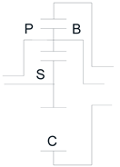
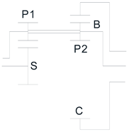
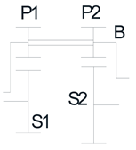
For this purpose, the following 4 trains shown in the table will be analyzed, using Levai's notation [24]:

Table 1.
Types of epicyclic gear trains.
| Model 1 | Model 2 | Model 3 | Model 4 |
 |
 |
 |
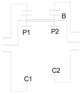 |
| P(P)N | P(PP)N | P(PP)P | N(PP)N |
Since we are looking for the most compact and smallest volume solution, we will analyze the Model 1 and determine how the operating parameters affect the gearbox design.
4. Kinematic analysis of the epicyclic gear train model 1
The same gear train can operate in six different ways depending on its fixed element according to the following table:
Table 2.
Epicyclic gear trains variants.
| Fixed Element | Input | Output | Variant |
|---|---|---|---|
| Planet carrier | Sun | Ring | 1 |
| Ring | Sun | 2 | |
| Sun gear | Ring | Planet carrier | 3 |
| Planet carrier | Ring | 4 | |
| Ring gear | Sun | Planet carrier | 5 |
| Planet carrier | Sun | 6 |
Table 3.
Relationship between input and output shaft speeds.
| Model 1 | ||
| Willis | 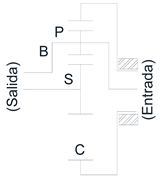 |
|
| Variant | Fixed Ring | |
| 6 | Input: Planet carrier Output: Sun |
Where: = angular velocity of the sun, = angular velocity of the planet carrier, = number of teeth of the crown, = number of teeth of the sun, = number of teeth of the planet. For model gear train 1, the highest gear ratios occur when the ring is fixed, the input is through the planet carrier arm and the output is through the sun and their values are shown in the table 3.
Taking into account the size of the planets in relation to the sun, the gear ratios are the following ones:
Table 4.
Gear ratios for epicyclic gear train model 1.
| 1/6 | 1/5 | ¼ | 1/3 | ½ | 1 | 2 | 3 | 4 | 5 | 6 | |
| 2.33 | 2.4 | 2.5 | 2.67 | 3 | 4 | 6 | 8 | 10 | 12 | 14 | |
| -1.33 | -1.4 | -1.5 | -1.67 | -2 | -3 | -5 | -7 | -9 | -11 | -13 | |
Considering a maximum tooth ratio of up to 6 for spur gears, a gear ratio =14 can be achieved.
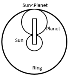
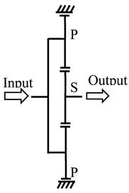
Table 5.
Gear train model 1.
 |
 |
5. Analysis of the multiplier gearbox multiplier
First, we will analyze the gearbox of a wind turbine for which we have the following design-engineering data:
Table 6.
Design-engineering data.
| Rated Power (P): | 7 MW |
| Transmission ratio ie/s | 107 ± 2 % |
| Optimal rotor speed | 14 rpm |
| Gear safety coefficient, X | 1.5 |
| Driving machine | Major shocks |
| Driven machine | Uniform operation |
| Φ (rotor diameter) | 180 m |
It is assumed a start-up wind speed of 4 m/s, a rated wind speed of 12 m/s and the wind turbine shutdown wind speed of 25 m/s.
It is considered that the wind delivers the rated maximum power at a wind speed of , which corresponds, depending on the rotor blade, to a rotor rotational speed of .
And that the rotational speed of the generator at that time is . Therefore, the transmission ratio will be considered to be . The diameter of the rotor blades is .
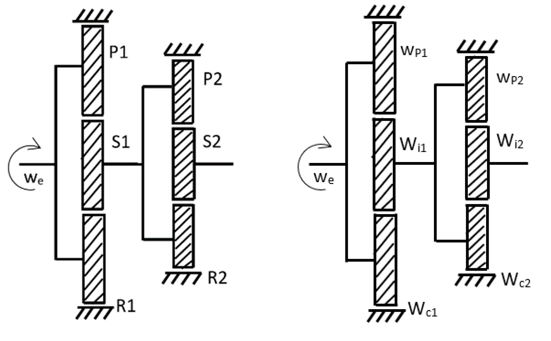
The gearbox will have two stages. In each stage there is an epicyclic gear train type model 1 variant 6 (it implies that the ring gear is fixed).
See figure below
Figure 1.
Multiplier gearbox with two stages.
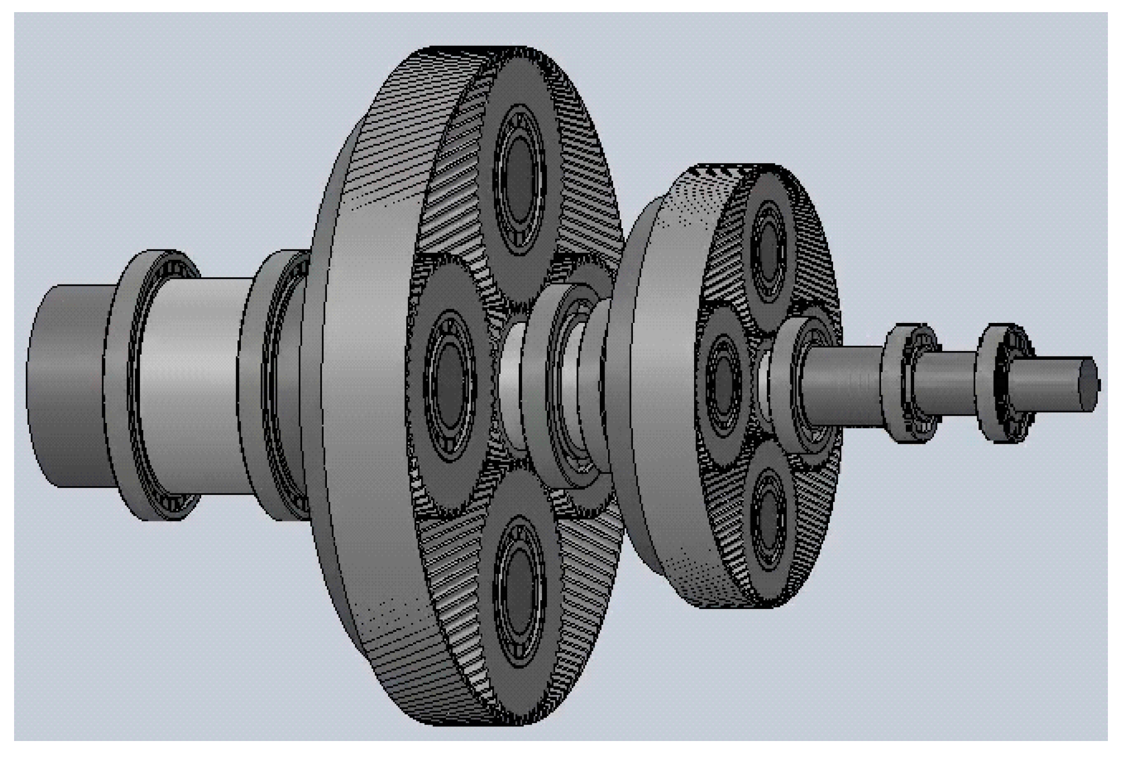
Figure 2.
Kinematic diagram.
The influence of the design parameters on the epicyclic gear train of stage 1 will be analyzed because it is the most critical, the one that bears the highest loads and therefore where the highest stresses occur.
Considering that the gear ratio is the same in each stage, it is considered that
, with
The sun is smaller than the planets, i.e., .
From the result of the analysis to be carried out, it is intended to design a gearbox of minimum weight and minimum area and volume capable of transmitting the rated power of the wind turbine P a transmission ratio of and a safety coefficient of X.
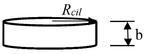
The volume of a gear is considered to be proportional to the volume of the cylinder containing the gear and having the same design parameters as the gear. It is indicated because the gear may have a hub and ribs that lighten the volume of the cylinder containing the gear.
Therefore:
where is the radius of the cylinder and its height. See the following figure:
The diameters of the gears Dengra depend on the diameter of the corresponding shaft d.
The shafts must be able to transmit a torque of magnitude T so it must have sufficient torsional stiffness according to the following expression:
Where is the shaft diameter, is the transmitted torque, is the transverse modulus of elasticity of the shaft material and is the torsional angle per unit length that is allowed to avoid failure due to high torsional angle.
From the maximum rated power that the wind turbine can generate (which in turn depends on the size of the wind turbine blades), the diameter of the input shaft to the gearbox, the diameter of the intermediate shafts and the output shaft for the model 1 epicyclic gear train will be calculated.
The pitch diameters of the gears must respect not only the value of the shaft diameter but also the desired transmission ratio between the input and output shafts ie/s and also the apparent transmission ratio defined by the Willis formula ia.
The mass of each gear may be calculated from the volume of each gear and the density of the material from which it is manufactured. Thus, for gear or constituent element i, the mass will be calculated as
In a simplified form, for the calculation of the mass of the epicyclic gear train, the gears involved, and the planet carrier will be considered. The real mass of the train will be proportional to that obtained in the simplified form. The intervention of auxiliary constituent elements, such as bearings, will not be taken into account at this stage of the analysis. Hence, the mass obtained from the present analysis is considered to be proportional to the actual mass of the epicyclic gear train, which can be calculated with sufficient accuracy later.
Once the wind turbine is in operation, the torque transmitted from the blades to the gearbox is calculated. The knowledge of the torque value allows to dimension the whole drive train and in particular the gearbox. In this work, the most important elements of the gearbox will be dimensioned, such as the shafts and the constituent gears.
Therefore, for the study and design of the gearbox it is essential to know the transmitted torques.
The maximum torque on the gearbox input shaft is calculated from the maximum design rated power of the wind turbine. The wind turbine is considered to produce a rated power of P= 7 MW. From the rotor speed that produces that maximum rated power, the transmitted torque is obtained:
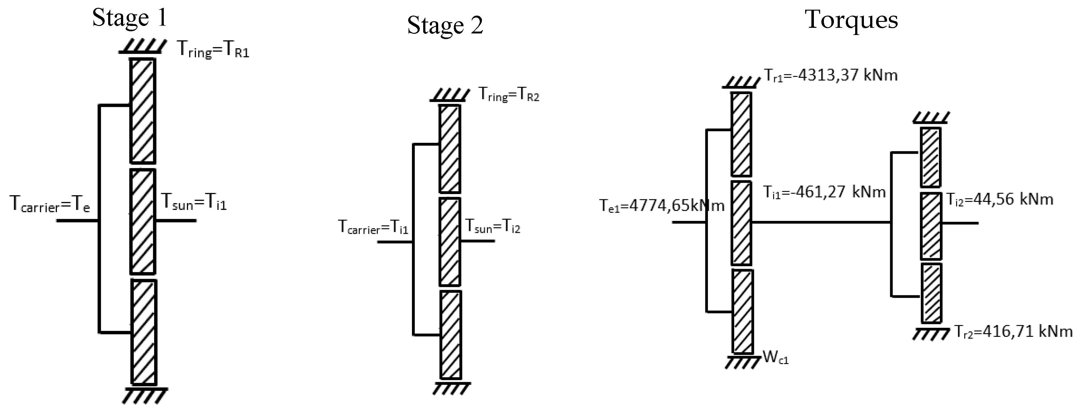
This torque arrives at the gearbox. It is transmitted to the first stage by the first stage epicyclic gear train planet carrier. See figure below:
It will be assumed that there are no frictional energy losses, which will allow us to calculate the torque transmitted on the shafts of this first stage using the following expressions:
- .
is the power reaching sun 1, is the power reaching ring 1 and is the power reaching planet Carrier 1.
- 2.
- .
is the torque acting on sun 1, is the torque supported by the ring 1 and is the torque acting on planet Carrier 1.
- 3.
Considering that , since the ring of the first stage is fixed, the torque on the intermediate shaft and, consequently, on the output shaft of the epicyclic gear train 1 can be obtained:
Next, the torque on the rest of the axes of each stage is calculated:
Stage E1: Input by Planet carrier B1 and output by sun S1. Then torque in the sun 1 is:
Stage E2: Input by Planet carrier B2 and output by sun S2. Then torque in the sun 2 is:
Assuming that the material of the shafts is steel with transverse stiffness modulus G=81 GPa and imposing a maximum value to the torsional deflection (1.5 °/m), the value of the diameters of each shaft is calculated. For the input shaft:
This value is coincident with that of the planet carrier of stage 1:
For the intermediate shaft:
For the output shaft:
Table 7.
Diameters of epicyclic gear train shafts.
| Shaft diameters (mm) | |
|---|---|
| de1 | 389.15 |
| dint | 216.95 |
| de2 | 120.957 |
Figure 3.
Kinematic diagrams and Diameters of epicyclic gear train shafts.
Next, the pitch diameters of the gears will be calculated. These diameters depend on the diameter of the shafts and parameters such as the tooth modulus.
Usually, as a first approximation, the pitch diameter of each gear will be obtained from the following formula.
As it can be seen, the diameter of each gear will depend on the theoretical normal modulus and , which is the depth of the keyway, which will be obtained from the shaft diameter according to standard DIN 6885.
However, in this work, the pitch diameter of each gear will be obtained from the following formula.
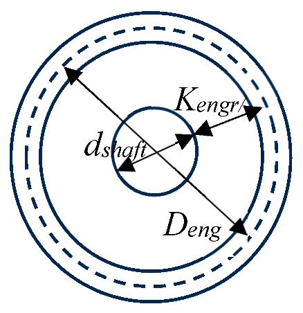
Where is the pitch diameter of the gear being analyzed. It can be the sun, planet or ring gear. is the diameter of the shaft supporting the gear. It must be sufficient to provide the required torsional stiffness. And is a constant parameter that will determine the size of the pitch diameter of the gears from the corresponding shaft diameter.
This parameter considers the apparent gear modulus , the tooth height and the value of (the depth of the keyway in the hub). In this work, the influence of this parameter on the value of the pitch diameter will be analyzed.
With the data of shaft diameters and , the values of the pitch diameters of the gears can be obtained.
On the other hand, the minimum number of teeth must also be considered to avoid interferences. As starting data, the normal pressure angle and the helix angle
are known for the calculation of the minimum number of teeth the following expressions are used:
In addition, the apparent modulus for spur gears is:
The pitch diameters of the gears must also comply with the required gear ratios.
A value in the maximum and minimum deviation of the epicyclic gear ratio of 1% will be assumed, therefore:
A table with possible solutions from various normalized modulus values will be elaborated. It must be considered that the geometrical values of gears obtained must fulfill a set of conditions.
The gearbox consists of two stages, each consisting of an epicyclic planetary gear train. The gear ratio will be equal in each stage and will have to be contained between the maximum and minimum values previously calculated.
The transmission ratio for the first stage, applying the Willis formula is:
The epicyclic gear model 1 has some geometrical characteristics that must be taken into account. One of them is the following:
That is, the pitch diameter of the ring is equal to the sum of the pitch diameter of the sun plus twice the pitch diameter of the planet.
It is also advisable to introduce as many satellites as possible so that the loads transmitted in the epicyclic train are better distributed and the risk of gear tooth failure is minimized.
The following geometrical conditions must be met for each stage:
- (a)
- coaxiality condition, derived from eq. (6):
- (b)
- mounting condition. The number of teeth of the sun plus the ring divided by the number of satellites must be a whole number:
- (c)
- contiguity condition. It translates into that is to say,
- (d)
- Maximum number of planets:
- (e)
- To avoid interference
For stage 1:
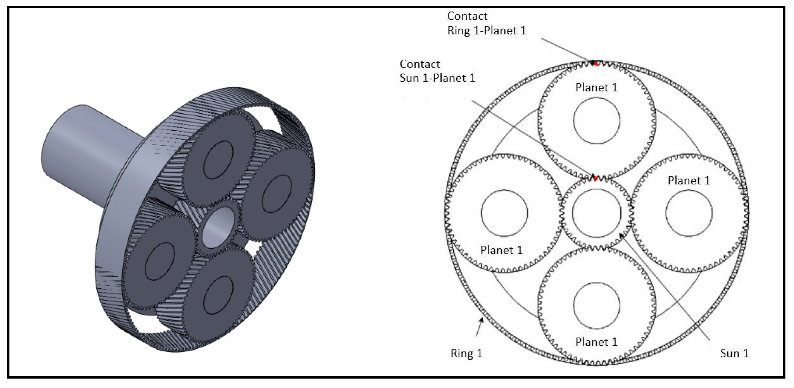
Figure 4.
Planets, sun and ring for stage 1.
5.1. Calculation of the weight of the epicyclic gear model 1:
In a simplified form, the weight of the epicyclic gear, related to the mass of the train, depends on the volume of each of its elements. It is proportional to the volume of the ring gear assembly, the planets, the sun, the planets carrier and the auxiliary elements such as bearings and bolts. Therefore:
Being the density of the material or materials used in the manufacture of the gears and other constituent elements of the epicyclic train.
On the other hand:
where:
In the above expressions is the width of the tooth, the pitch diameter of the sun at stage 1, the pitch diameter of a planet at stage 1, is the normal modulus, is the number of planets at stage 1.
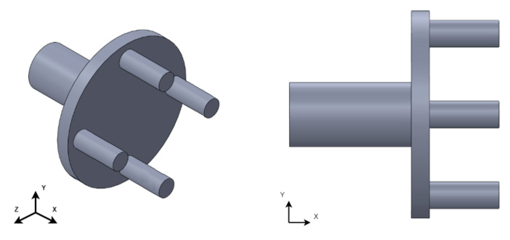
Figure 5.
Planet carrier for epicyclic gear model 1.
The determinant value to fulfil the geometrical conditions a), b), c) and d) is the pitch diameter of each gear, from which the number of teeth of the gears will be calculated. This in turn is calculated from the diameter of the corresponding shaft, see eq. (1):
For small values of the value of is also small. This circumstance means that the thickness of tooth "", in order to meet the sizing criteria for a material with known strength characteristics, is very high. These criteria are:
- (a)
- Tension at the base of the tooth:
- (b)
- Surface pressure on the tooth:
That means that to obtain reasonable values of " " it is necessary to increase the value of .
Next, a series of results for the gear diameters and for the mass of the epicyclic gear of stage 1 will be obtained from the following values of normal moduli:
| 10 | 15 | 20 | 25 | 30 | 35 | 40 | 45 | 50 | 60 | 70 | 80 | 90 | 100 |
The relationship between and and is determined by eq. (3). For the calculation of , stress supported by the teeth due to surface pressure, we use the following expression:
Considering that the following condition must be fulfilled:
Where maximum allowable contact stress and is the safety coefficient at maximum pressure. It will be taken as
From equation (14) (the tooth width to avoid surface pressure failure) will be obtained. The calculation of the tooth width follows an iterative process. To start the iterative process, a starting material with known allowable stresses , an estimate of the type of lubricant required and an initial modulus will be assumed. The stresses appearing at the tooth-to-tooth contact due to pressure and at the tooth base due to bending will be calculated. These stresses are compared with the allowable stresses of the material.
In eq. (13):
is the transmitted tangential force. It is calculated as with the angular velocity of the pinion (sun), the number of planets and is the radius of the pinion (sun),
is the pitch diameter of the pinion. is the width of the pinion tooth to resist the surface pressure. Gear ratio . is the geometrical coefficient ( is the apparent pressure angle and is the helix angle at the base of the tooth). is the elastic coefficient with and being the Poisson's coefficient and the elastic coefficient of wheel and pinion. is the driving coefficient. It depends on the tooth width. helix angle factor. is the application coefficient. It is consulted in tables. is the dynamic coefficient. The constants , and depend on the tooth type, finish quality, rotational speed, number of teeth and gear ratio. is the transverse load distribution coefficient. is the longitudinal load distribution coefficient. The tooth width is obtained by isolating from (13):
To check for failure by breakage at the base of the tooth, the bending stress supported by the teeth is calculated:
Where: is the shape coefficient, where is the virtual number of teeth. is the driving coefficient. is the driving ratio. is the stress concentrator coefficient. is the slope coefficient. is the hoop thickness coefficient. is the longitudinal load distribution coefficient. is the transverse load distribution coefficient. It depends on the finish quality (). Defining the tooth fracture safety coefficient as:
the process of calculating the tooth width " " ends when
6. Results and Discussion
For simplicity, only the first stage epicyclic gear train will be analyzed. The following design data are assumed:
Table 8.
Design data for epicyclic gear trains stage 1.
| P | |
From the solution of equations (1) to (18), the values represented in the following tables are obtained, which provide data on the characteristics of the gears forming the epicyclic train of stage 1.
Table 9.
For Kengr1=6∙mt, and hardening steel.
| dcarr1 | ds1 | Ds1 | zs1 | zp1 | zcor1 | iap1 | b | W | |
|---|---|---|---|---|---|---|---|---|---|
| mn=10 | 389.15 | 216.95 | 280.80 | 26 | 109 | 244 | 9.38 | >2500 | No |
| mn=15 | 389.15 | 216.95 | 312.73 | 20 | 84 | 188 | 9.4 | >2500 | No |
| mn=20 | 389.15 | 216.95 | 344.65 | 16 | 67 | 150 | 9.37 | >2500 | No |
| mn=25 | 389.15 | 216.95 | 376.58 | 14 | 59 | 132 | 9.42 | >2500 | No |
| mn=30 | 389.15 | 216.95 | 408.51 | 14 | 55 | 123 | 9.46 | >2500 | No |
The table above shows, for different values of the normal values of the normal modulus mn, the values of the diameter of the input shaft to the epicyclic gear train of stage 1, which corresponds to the planet carrier (dcarr1), diameter of the sun axis in stage 1 (ds1), the pitch diameter of the sun in stage 1 (Ds1), the number of teeth of the sun (zs1), of the planets (zp1) and ring at stage 1 (zcor1), the apparent gear ratio in stage 1 (iap1), tooth width for all stage 1 gears (b) and a proportional estimate of the weight of the epicyclic gear train (W). It can be noticed that for any value of mn, the value of the tooth width is excessive. Also, the pitch diameter Ds1 is small due to the low value of , see eq. (2), which means that the tooth width is too large to comply with the safety coefficients (eq. (14) and (18)) and the weight of the planetary train of the first stage is excessive. In addition, from the normal modulus 25, interference in the sun of stage 1 is reached, see eq. (3), so that it is not possible to use larger moduli.
It is concluded that is useless. The data obtained correspond to a case hardening steel which has very high permissible stress limits. Any other material with lower levels of stress limits would worsen the results. The next step is to increase the value of .
Table 10.
For . These data are obtained*.
| dbra1 | ds1 | Ds1 | Zs1 | Zp1 | Zcor | Iap1 | b2 | M2 | |
|---|---|---|---|---|---|---|---|---|---|
| mn=10 | 389.15 | 216.95 | 376.58 | 35 | 146 | 327 | >2500 | Sin | |
| mn=15 | 389.15 | 216.95 | 456.39 | 29 | 121 | 271 | >2500 | Sin | |
| mn=20 | 389.15 | 216.95 | 536.21 | 25 | 105 | 234 | >2500 | Sin | |
| mn=25 | 389.15 | 216.95 | 616.02 | 23 | 96 | 215 | 742 | 138.44 | |
| mn=30 | 389.15 | 216.95 | 695.83 | 22 | 92 | 206 | 467 | 115.60 | |
| mn=35 | 389.15 | 216.95 | 775.65 | 21 | 88 | 196 | 353 | 109.16 | |
| mn=40 | 389.15 | 216.95 | 855.46 | 20 | 84 | 187 | 305 | 112.61 | |
| mn=45 | 389.15 | 216.95 | 935.27 | 20 | 84 | 187 | 248 | 115.87 | |
| mn=50 | 389.15 | 216.95 | 1015. | 19 | 880 | 178 | 227 | 116.64 | |
| mn=60 | 389.15 | 216.95 | 1174.7 | 18 | 75 | 168 | 178 | 119.39 | |
| mn=70 | 389.15 | 216.95 | 1334.3 | 18 | 75 | 168 | 130 | 118.64 | |
| mn=80 | 389.15 | 216.95 | 1494 | 18 | 75 | 168 | 99 | 117.04 | |
| mn=90 | 389.15 | 216.95 | 1652.6 | 17 | 71 | 159 | 87 | 117.75 | |
| mn=100 | 389.15 | 216.95 | 1813.2 | 17 | 71 | 159 | 69 | 115.84 |
Table 11.
For . These data are obtained*.
| d1 | ds1 | Ds1 | Zs1 | Zp1 | Zcor | Iap1 | b3 | M3 | |
|---|---|---|---|---|---|---|---|---|---|
| mn=10 | 389.15 | 216.95 | 429.79 | 40 | 167 | 374 | 9.35 | >2500 | Sin |
| mn=15 | 389.15 | 216.95 | 536.21 | 34 | 142 | 318 | 9.35 | >2500 | Sin |
| mn=20 | 389.15 | 216.95 | 642.62 | 30 | 126 | 282 | 9.4 | 611 | 121.41 |
| mn=25 | 389.15 | 216.95 | 749.04 | 28 | 117 | 262 | 9.35 | 391 | 106.66 |
| mn=30 | 389.15 | 216.95 | 855.46 | 27 | 113 | 253 | 9.37 | 274 | 100.65 |
| mn=35 | 389.15 | 216.95 | 961.88 | 26 | 109 | 244 | 9.38 | 230 | 107.01 |
| mn=40 | 389.15 | 216.95 | 1068.3 | 25 | 105 | 235 | 9.4 | 196 | 110.91 |
| mn=45 | 389.15 | 216.95 | 1174.7 | 25 | 105 | 235 | 9.4 | 157 | 112.37 |
| mn=50 | 389.15 | 216.95 | 1281.1 | 24 | 100 | 224 | 9.33 | 139 | 112.15 |
| mn=60 | 389.15 | 216.95 | 1494.0 | 23 | 96 | 215 | 9.34 | 105 | 112.68 |
| mn=70 | 389.15 | 216.95 | 1706.8 | 23 | 96 | 215 | 9.34 | 76 | 110.62 |
| mn=80 | 389.15 | 216.95 | 1919.6 | 23 | 96 | 215 | 9.34 | 57 | 108.85 |
| mn=90 | 389.15 | 216.95 | 2132.5 | 22 | 92 | 206 | 9.36 | 49 | 108.69 |
| mn=100 | 389.15 | 216.95 | 2345.3 | 22 | 92 | 206 | 9.36 | 39 | 107.21 |
Table 12.
For . These data are obtained*.
| d1 | ds1 | Ds1 | Zs1 | Zp1 | Zcor | Iap1 | b4 | M4 | |
|---|---|---|---|---|---|---|---|---|---|
| mn=10 | 389.15 | 216.95 | 536.21 | 50 | 209 | 468 | 9.36 | >2500 | Sin |
| mn=15 | 389.15 | 216.95 | 695.83 | 44 | 184 | 412 | 9.36 | 443 | 105.26 |
| mn=20 | 389.15 | 216.95 | 855.46 | 40 | 167 | 374 | 9.35 | 274 | 95.69 |
| mn=25 | 389.15 | 216.95 | 1015.1 | 38 | 159 | 356 | 9.36 | 194 | 96.22 |
| mn=30 | 389.15 | 216.95 | 1174.7 | 37 | 155 | 347 | 9.37 | 151 | 102.17 |
| mn=35 | 389.15 | 216.95 | 1334.3 | 36 | 151 | 338 | 9.38 | 120 | 104.09 |
| mn=40 | 389.15 | 216.95 | 1494 | 35 | 146 | 327 | 9.34 | 99 | 105.55 |
| mn=45 | 389.15 | 216.95 | 1653.6 | 35 | 146 | 327 | 9.34 | 78 | 105.74 |
| mn=50 | 389.15 | 216.95 | 1813.2 | 34 | 142 | 318 | 9.35 | 64 | 105.99 |
| mn=60 | 389.15 | 216.95 | 2132.5 | 33 | 138 | 309 | 9.36 | 49 | 105.46 |
| mn=70 | 389.15 | 216.95 | 2451.7 | 33 | 138 | 309 | 9.36 | 36 | 104.2 |
| mn=80 | 389.15 | 216.95 | 2771.0 | 33 | 138 | 309 | 9.36 | 27 | 103.05 |
| mn=90 | 389.15 | 216.95 | 3090.2 | 32 | 134 | 300 | 9.37 | 23 | 102.53 |
| mn=100 | 389.15 | 216.95 | 3409.5 | 32 | 134 | 300 | 9.37 | 18 | 101.69 |
*alloy steel, hardened and tempered.
The Figure 6 and 7, relates the modulus to the width of the tooth and to the weight of the epicyclic gear train of stage 1, respectively.
From Figure 6, it can be seen that the tooth width decreases when increasing the module and the pitch diameter through the parameter . The larger the (>>) the smaller the tooth width is.
From Figure 6 and 7, it can be notice that not all modules are usable, either because they give rise to interferences in the teeth or because the width "b" of the teeth exceeds the value of 2D, which is the recommended value.
In Figure 7, there is an aspect that is not intuitive and very important: when the size of the pitch diameter increases (>>) the weight decreases.
Also, the weight first decreases and then it increases as the modulus increases.
This means that there is a value for that minimizes the weight of the epicyclic gear train by acting on the value of the diameters and the tooth width.
It is also observed that the weight increases above a certain value of the normal modulus for each .
In Figure 8, it is shown that the larger the pitch diameter, the higher the bending strength at the base of the tooth is.
On the other hand, the bending strength at the base of the tooth decreases slightly as the normal tooth modulus increases.
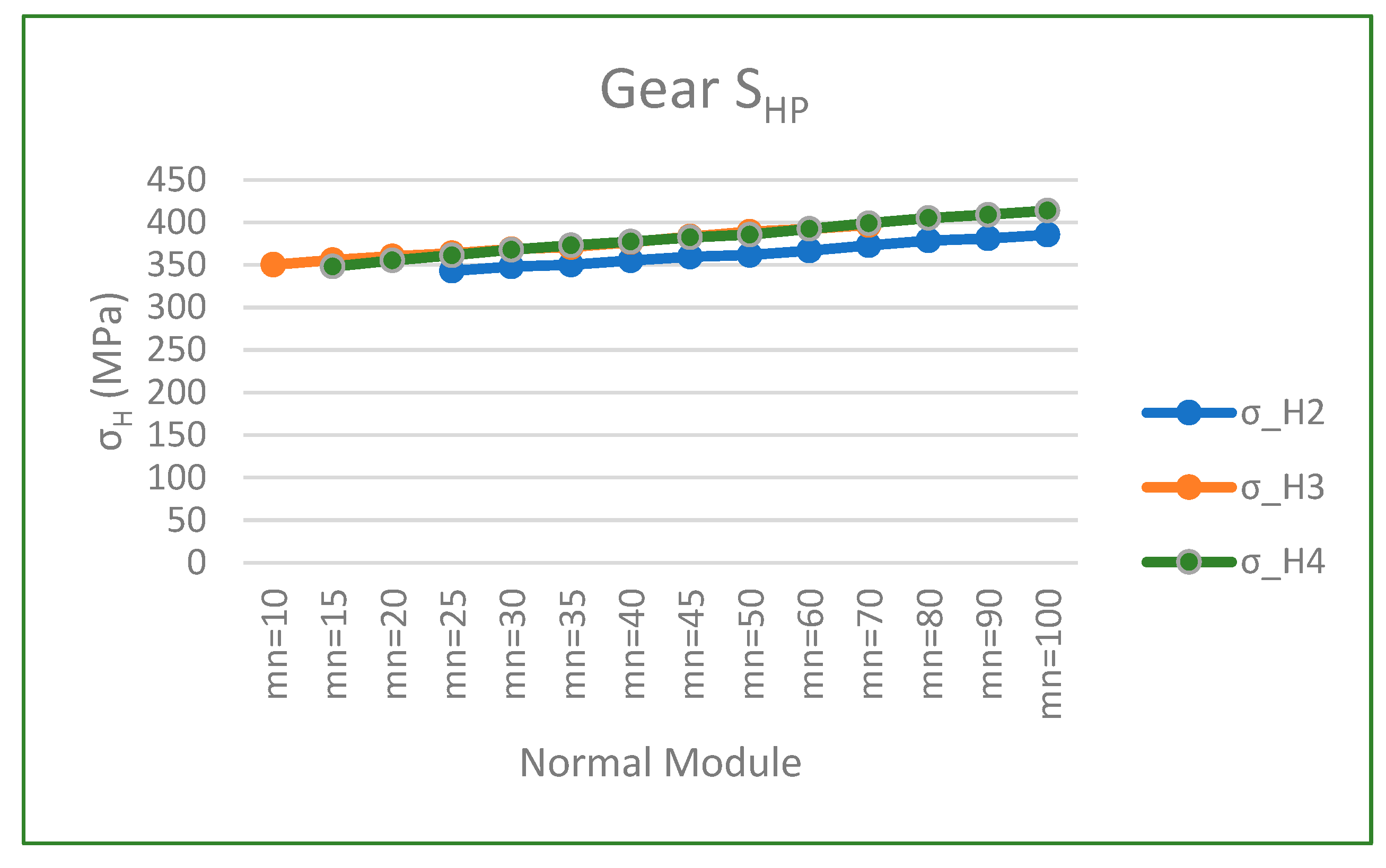
In Figure 9, it is shown that the greater the pitch diameter, the higher the surface pressure resistant limit. On the other hand, the bending strength at the base of the tooth increases slightly as the normal tooth modulus increases.
7. Conclusions
For very small values of (with ), the resulting gearing is also too small and results in the width of tooth "b" being too large to support the stresses generated in the teeth. Therefore, the value of the pitch diameter must be increased.
It has also been observed that the width of tooth "b" decreases when the pitch diameter of the gears is increased (). The larger the (>>) the smaller the tooth width is.
Another item observed is that the tooth width decreases as the value of the normal modulus increases.
On the other hand, not all moduli are usable, either because they give rise to interferences in the toothing or because the width "b" is too large or too small (b> 2D, or b<< D, far from the recommended values).
It can also be seen that when the size of the pitch diameter increases (>>) the weight decreases.
This means that there is a value for that minimizes the weight of the gears by acting on the value of the diameters and the value of the tooth width. This results in a minimization of the weight of the epicyclic gear train model 1.
References
- Carriveau, R, 2012. Advances in wind power. Edited by Rupp. InTech Janeza Trdine 9, 51000 Rijeka, Croatia. 374 p. ISBN 978-953-51-0863-4. [CrossRef]
- Nejad et al., 2022. Wind turbine drivetrains: state-of-the-art technologies and future development trends. Wind Energ. Sci., 7, 387–411.
- Chauhan, A., Singla, A., Panwar, N., Jindal, P., 2014. CFD Based Thermo-Hydrodynamic Analysis of Circular Journal Bearing. International Journal of Advanced Mechanical Engineering 4(5), 475-482.
- Florescu, A., Barabas, S, Dobrescu, T., 2019. Research on Increasing the Performance of Wind Power Plants for Sustainable Development, Sustainability, . [CrossRef]
- Oyague, F., 2009. Gearbox Modeling and Load Simulation of a Baseline 750-kW Wind Turbine Using State-of-the-Art Simulation Codes. National Renewable Energy Laboratory. Technical Report NREL/TP-500-41160. 94 p.
- Zhao, M., Ji, J., 2016. Dynamic Analysis of Wind Turbine Gearbox Components. Energies, 9, 110. [CrossRef]
- Hari Babu, A.V., Naresh, P., Madhava, V. and Sudhakar Reddy, M., 2016, Minimum Weight Optimization of a Gear Train by Using GA, in International Journal of Engineering Trends and Advanced Sciences 1(2), pp. 43-50.
- Hart, et al., 2019. A review of wind turbine main-bearings: design, operation, modelling, damage mechanisms. [CrossRef]
- Musial, W.D., Beiter, P.C., Nunemaker, J., Heimiller, D.M., Ahmann, J., Busch, J., 2019, Oregon Offshore Wind Site Feasibility and Cost Study; National Renewable Energy Lab.: Golden, CO, USA,.
- Hau, E., 2011, Wind Turbines, Fundamentals, Technologies, Application, Economics, Springer, . [CrossRef]
- Ragheb, A. M., and Ragheb, M., 2011, Wind Turbine Gearbox Technologies, . [CrossRef]
- Zaretsky, E.V., et. al., 2007, Probabilistic Analysis of Space Shuttle Body Flap Actuator Ball Bearings, NASA.
- Kaiser, S., Fröhlingsdorf, M., 2007. The Dangers of Wind Power, In: Spiegel, http://www.spiegel.de/international/germany/0,1518,500902,00.html.
- Tiwari, P., Kumar, V., 2014. Analysis of Hydrodynamic Journal Bearing Using CFD and FSI Technique. International Journal of Engineering Research & Technology 3(7).
- Nie, M., Wang, L., 2013. Review of condition monitoring and fault diagnosis technologies for wind turbine gearbox. Procedia CIRP 11, 287–290.
- Department of Energy, 2010, Wind Turbine Testing in the NREL Dynamometer Test Bed, http://www.doe.gov/bridge.
- Struggl, S., Berbyuk, V., Johansson, H., 2015. Review on wind turbines with focus on drive train system dynamics. Wind Energy. 18, 567–590. [CrossRef]
- Tauviqirrahman, M. et al., 2021. CFD Analysis of Journal Bearing with a Heterogeneous Rough/Smooth Surface. Lubricants, 9, 88. [CrossRef]
- Rubio, F., Llopis-Albert, C., Zeng, S., 2022. Best practices and syllabus design and course planning applied to mechanical engineering subjects. Multidisciplinary Journal for Education, Social and Technological Sciences,9(2), 123-137. [CrossRef]
- Llopis-Albert, C., Rubio, F., Zeng, S., Devece, C., Torner-Feltrer, M.E., 2023. Quality assessment program of the teaching activity of the higher education faculty staff. A case study. Multidisciplinary Journal for Education, Social and Technological Sciences, 10(1), 94-113. [CrossRef]
- Llopis-Albert, C., Rubio, F., Zeng, S., Grima-Olmedo, J, Grima-Olmedo, C., 2022. The Sustainable Development Goals (SDGs) applied to Mechanical Engineering. Multidisciplinary Journal for Education, Social and Technological Sciences, 9(1), 59-70. [CrossRef]
- Hoehn, B.R., Stahl, K., and Gwinner, P., 2013, Light Weight Design for Planetary Gear Transmissions, Gear Technology 30, pp. 96-103.
- Vázquez-Hernández, C., Serrano-González, J., Centeno, G., 2017. A Market-Based Analysis on the Main Characteristics of Gearboxes Used in Onshore Wind Turbines. Energies, 10, 1686; [CrossRef]
- Levai, Z.,1968, Structure and Analysis of Planetary Gear Trains, Jnl. Mechanisms Volume 3, pp.131-148.
Figure 6.
Tooth width and normal gear module.
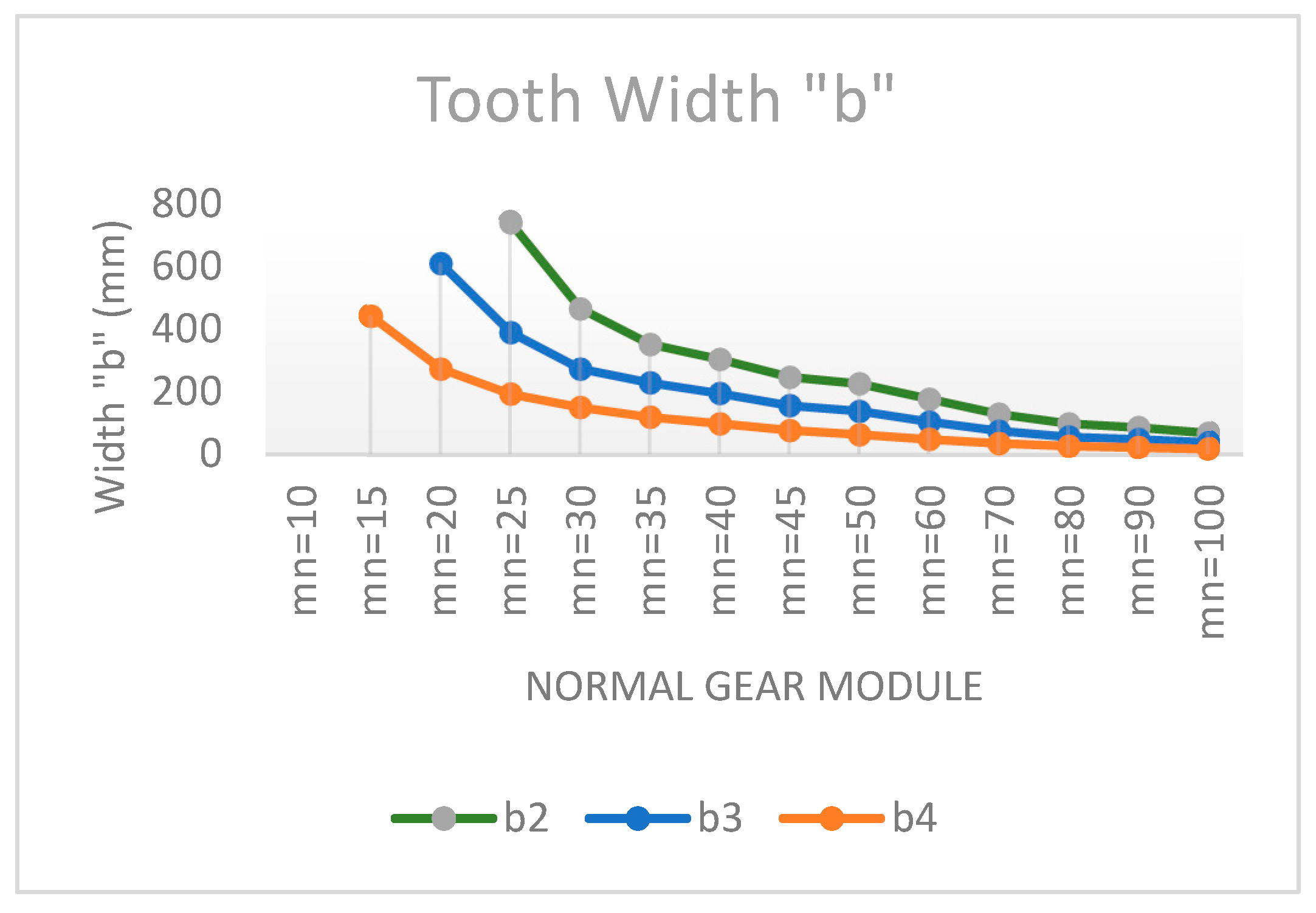
Figure 7.
Train weight width and normal gear module.
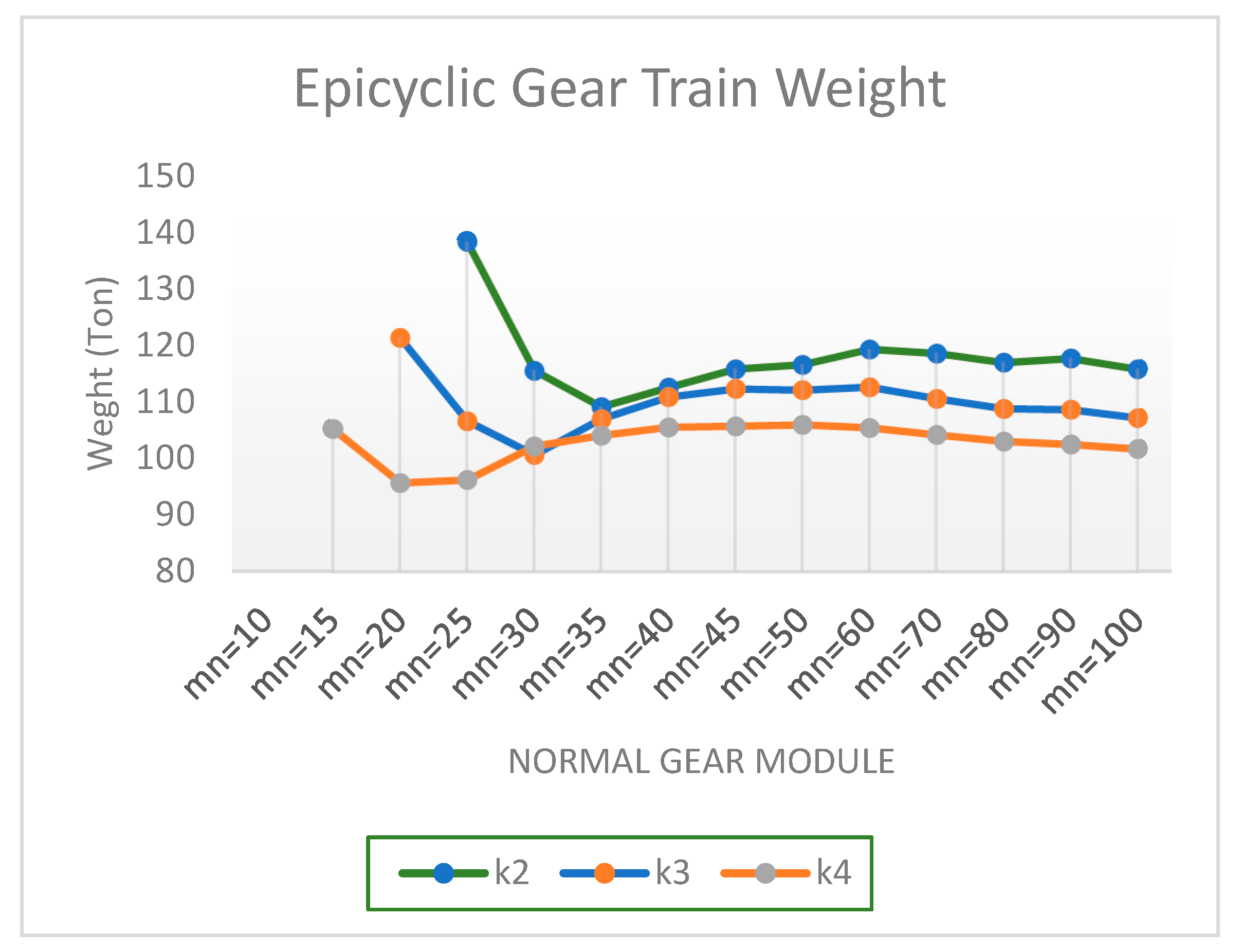
Figure 8.
SFP and normal module.
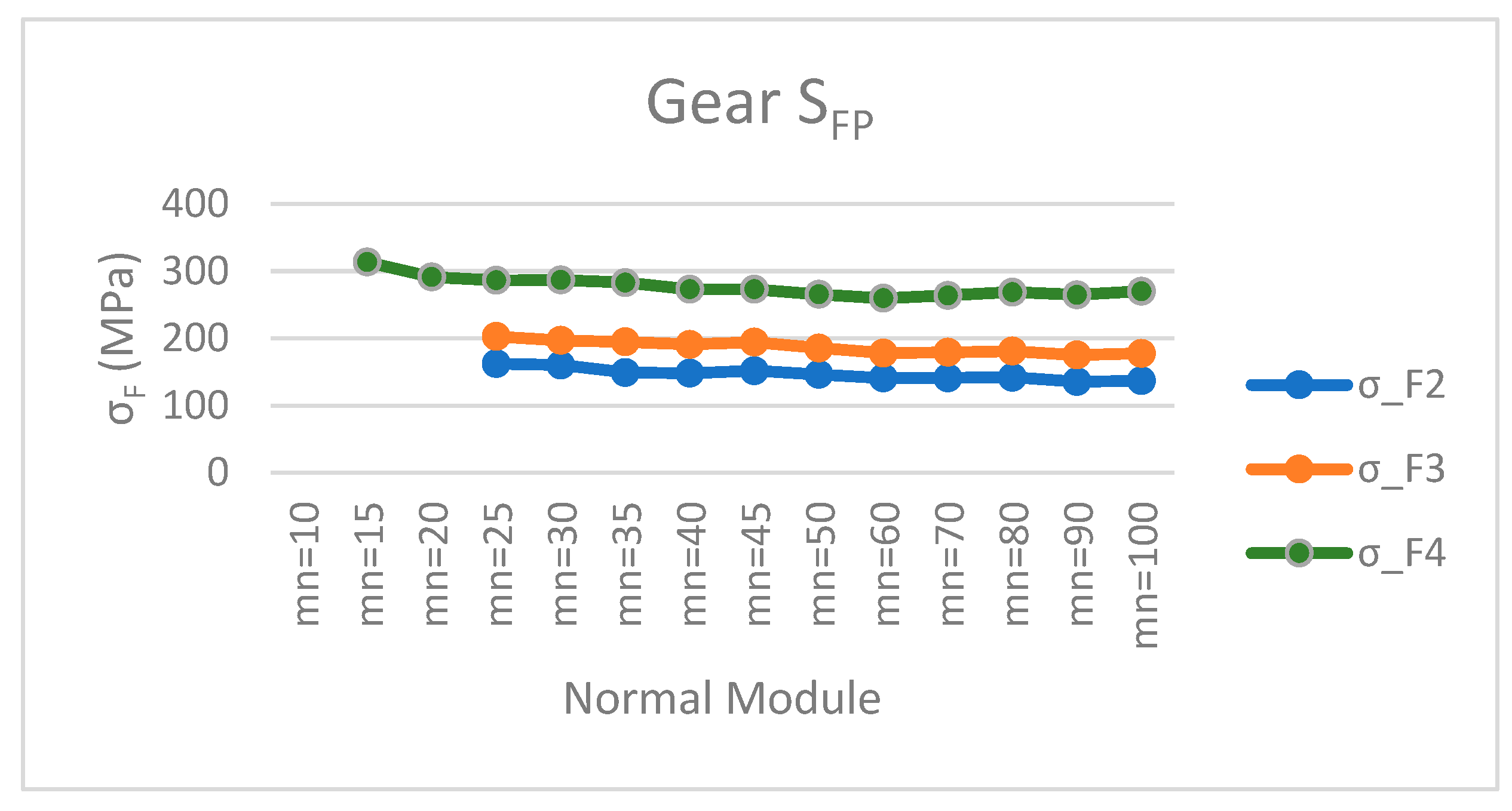
Figure 9.
SHP and normal module.
Disclaimer/Publisher’s Note: The statements, opinions and data contained in all publications are solely those of the individual author(s) and contributor(s) and not of MDPI and/or the editor(s). MDPI and/or the editor(s) disclaim responsibility for any injury to people or property resulting from any ideas, methods, instructions or products referred to in the content. |
© 2023 by the authors. Licensee MDPI, Basel, Switzerland. This article is an open access article distributed under the terms and conditions of the Creative Commons Attribution (CC BY) license (https://creativecommons.org/licenses/by/4.0/).
Copyright: This open access article is published under a Creative Commons CC BY 4.0 license, which permit the free download, distribution, and reuse, provided that the author and preprint are cited in any reuse.


