

Submitted:
14 September 2024
Posted:
18 September 2024
You are already at the latest version
Abstract
The geometry of structural members can influence the fatigue crack growth rate. In the paper, the T-stress depending on the element's geometry is used to quantify the effect of geometry on the fatigue crack growth rate. A series of fatigue tests on three-point bending specimens with different initial crack lengths were conducted. As a result, the dependence of the crack growth rate on the T-stress value was obtained.
Keywords:
fatigue crack growth
; Paris’ law
; in-plane constraints
; brittle fracture
; Williams’ solution
1. Introduction
In 1957 M.L. Williams [1] developed formulas for stress distribution in front of the crack. The solution has the form of a series of terms. Physical analysis lets to limit the number of elements in a series but still, there is a series of terms. Usually, only the first term, as a dominating, was used to describe the stress field in the neighborhood of the crack tip [2]. In his analysis, Williams assumed that the body is infinite. In reality, a body has a finite size and shape that influence the fracture toughness. This was taken into account in the standard [3] by strict requirements for the shape and dimensions of a specimen for the test to be valid.
In 1973 Larsson and Carlsson [4] showed that the size and shape of the plastic zone ahead of the crack tip depends on the in-plane geometry of the specimen. The influence of the specimen geometry can be considered by the value of the T-stress which is the second term of Williams' expansion.
In the case of elastic-plastic materials, the stress field is explained by the Hutchinson, Rice, and Rosengren equations [5], [6]. They describe so called HRR field. In this case, there is also the quantity that is equivalent to the T-stress. The full solution for HRR field was given by Yang S., Chao Y.J. and Sutton M.A. [7], but the Shih's and O’Dowd's approach turneda out to be more popular, mainly due to its simplicity [8], [9], [10], [11]. In this case, the equivalent of the T-stress is the Q-stress, which is the sum of all higher-order elements of the asymptotic expansion. In [9] the simple relationship between fracture toughness and Q-stress value is given.
The influence of in-plane constraints on the fatigue process in the crack initiation phase and in the ultra-low-cycle fatigue range was shown in [12] and [13]. These works showed that the Q/T-stress level affects not only the fatigue crack growth rate and the number of cycles to crack initiation but also the crack initiation site.
There are many laws of fatigue crack growth, but the most popular and comprehensive is Paris' law [14] which can be written as:
where a is the crack growth in millimeters per cycle, N is the number of cycles, C and m are material constants,
ΔK is a range of the stress intensity factor (SIF) changes, ΔKop is the SIF value when crack starts to open, R is a stress ratio.
As it results from equation (1), the rate of fatigue crack growth depends primarily on the load, which affects the range of changes in the stress intensity factor, but also on the stress ratio, i.e. on the average load [15], [16], [17]. The last quantity is the threshold value of the stress intensity factor at which the crack opens. Unfortunately, the fatigue cracking process is too complicated to be described by formula (1) alone. Therefore, research at the current stage of scientific development tries to take into account other factors. One of the elements that are difficult to describe mathematically is the effect of the environment. In the work [18], the effect of humidity and temperature was studied simultaneously. This effect was included by describing the changes in the parameters C and m in Paris's law.
Much more difficult to control is the effect of aggressive environment [19]. In such case, the simplest tool to show the effect of the selected factor is the Paris equation plot.
It is equally difficult to describe the effect of the material microstructure on the crack growth rate. For example, in [20] the effect of microstructure on the crack initiation site and the fatigue crack growth path was analyzed in welded joints. In [21] many aspects of fatigue crack growth in railway rails were studied, and one of the elements taken into account was the grain size. It was found that a finer microstructure requires a greater number of cycles to failure and thus reduces the crack growth rate. In [22] the effect of the inhomogeneity of the structure (clusters of small grains near large grains) on the fatigue crack initiation site was studied, as well as how the structure affects the crack growth in its initial phase.
The influence of individual parameters can be enhanced by their mutual influence [23], which is why artificial intelligence is increasingly used to assess the influence of selected parameters on the fatigue process [24], [25].
The influence of parameters that is much easier to describe mathematically is the influence of material properties on fatigue behavior [26]. The influence of the geometry of the tested element seems to be much more important and less intuitive to predict. The importance of the influence of geometry results from the fact that the shapes of elements used in industry differ significantly from the specimens used in laboratories. The mathematical formulation of the influence of geometry will allow for direct transfer of results from the laboratory to engineering practice. Fatigue cracks in structural elements often behave in a way that is difficult to predict. The growth of the crack may differ significantly from the model described by Paris's law, calculated in the laboratory using standard specimens. The main reason for this state of affairs is the geometry of the structural element, because the material used in the tests is usually the same as the one from which the structural element is made. The influence of geometry is divided into two groups due to the constraints that geometry imposes on the development of plastic zones. The influence of thickness on the growth rate of fatigue cracks was tested in [27], and [28]. Thickness creates so-called out-of-plane constraints. The shape and dimensions of the element in turn, constitute the second group of constraints, i.e. in-plane constraints.
The influence of the shape and dimensions of the elements on fatigue behavior are taken into account in different ways. The most popular approach uses the stress concentration factor [29]. The problem in this case is that different formulas are used for each geometry. That is why in [30] the normalized stress gradient is used.
In view of the findings of Larsson and Carlsson [4] combined with the results of O’Dowd [9] in the field of monotonic loading, it seems quite obvious to try to use a two-term approach to describe fatigue crack growth. An additional advantage of such an approach would be a uniform approach to the influence of geometry. Regardless of the shape of the element, the influence of geometry would be described by the same equations.
This paper presents preliminary studies of fatigue crack growth rates for different levels of in-plane constraints.
2. Materials and Methods
The tests were carried out on specimens made of C45 steel (1.0503/1045). The values of material constants achieved in the tensile tests are presented in Table 1 and Figure 1a.
The fatigue load amplitude was made dependent on the critical value of the SIF. To determine it, three three-point bending specimens are prepared with a thickness of t=10 mm and other dimensions proportional to this thickness in accordance with the standard [3]. As a result of the experiments, an average value of K IC=53,5MPa√m was obtained.
The next step was to make a set of three-point bending specimens with a thickness of t=10 mm and other dimensions in accordance with the standard [3] except for the crack length. Three different crack lengths are introduced to the specimens to obtain the relative crack length a/W=0.25, 0.5, 0.75, where a is the crack length and W is the specimen width.
The specimens were subjected to fatigue loading with repeating cycles of two maximum values: 0.77KIC and 0.5KIC, while minimum value was always the same and equal 0.1kN. Zero force value was not used due to the possibility of loss of contact between the actuator and the specimen. The force values corresponding to the assumed maximum SIF levels were determined based on the formula (3) [31]:
where α=a/W, and , and other undefined parameters are presented in the Figure 2.
The number of cycles at which the crack growth reached 1 mm and 2 mm was recorded. Crack growth measurements were made optically on the surface of the specimens.
The maximum forces used to load the samples are shown in Table 2.
To determine the T-stress values, numerical calculations performed in the ABAQUS/CAE 2017 program were used. The specimens were modeled in plane strain using 4-node bilinear elements (CPE4R). Taking advantage of the problem symmetry, only half of the specimen is modeled. In each specimen, the zone in the vicinity of the crack is modeled as a rectangle composed of two squares filled with elements of size 0.003 mm x 0.003 mm (Figure 3). The size of the elements near the crack tip guarantee stable and accurate results. The model is composed of over 230 thousand elements. The exact number depends on the crack length. For a/W= 0.25 and a/W=0.75, it was 233 thousand elements; for a/W=0.5, it was 236 thousand elements. The loading roller and support roller were modeled as rigid bodies. The displacement was applied to the appropriate roller. Its value is sufficient to obtain the required K-values. The T-stress values was determined automatically by the ABAQUS program.
3. Results
During the tests, the number of cycles was recorded after reaching an increase of 1 mm and 2 mm. The measurement results were an average of three samples. In the case of the longest cracks, i.e. a/W=0.75, it was not possible to determine the average. In the case of the lower load level, no increase was observed or it was very small, therefore the tests were stopped after exceeding 1,000,000 cycles, but at a higher load level, one of the specimens broke suddenly before reaching an increase of 2 mm.
Table 3 and Table 4 show the average results of measurements of the number of cycles required to achieve the assumed increase.
The T-stress values at the beginning of loading for each load case determined by numerical calculations are presented in Table 5.
4. Discussion
In all cases, the initial load had the same parameters. Both the maximum load value and the stress ratio are identical, nevertheless, the number of cycles to achieve the intended increments is clearly different (Figure 4).
With the crack length increase at constant force, the maximum value of the stress intensity factor (3) increases, and thus the range of its changes. The maximum values of SIF for assumed increments are shown in Table 6 and Table 7.
As can be seen from Table 6 and Table 7, the SIF value as a result of crack growth increases faster for longer cracks, but the crack growth rate behaves oppositely. The difference in the obtained number of cycles between the specimens increases. For an increase of 2 mm in the case of a higher load, the critical SIF value was reached for all lengths, and despite this, the specimens did not fail rapidly except for the sample with a/W = 0.75. However, in this case, the SIF exceeded the critical value by 67%. This geometry should have already failed for an increase of 1 mm, corresponding to an increase in SIF to 58 MPa√m.
Comparing the obtained increases with the stress values T, a close correlation can be seen. Specimens with a higher T-stress value were characterized by lower fatigue crack growth or its arrest, while low values promoted the acceleration of crack growth (Table 8 and Table 9).
This behavior can be explained by the influence of the level of in-plane constraints on the value of principal stresses. In the case of plane strain, the stress in the thickness direction are equal , where ν is Poisson's ratio, σ3 is the stress in thickness direction, and σ1, σ2 are the stresses in the other directions (i.e. in the specimen plane) and therefore the maximum shear stress depends on the stresses σ1 and σ2. In the case considered, on the crack growth path, the stress level σ2 depends on the SIF value while σ1 is equal to the T-stress. As can be seen in Figure 5 value of maximum shear stress depends on the T-stress. The lower is the T-stress value the higher is maximum shear stress.
5. Conclusions
Tests were carried out in which specimens with different levels of the T-stress were loaded with repeating cycles of the same amplitude of SIF. Different crack growth rates were obtained for each geometry for two levels of loading. These rates are correlated with the level of in-plane constraints described by T-stress values. The lower the T-stress the greater the fatigue crack growth rate. The results indicate the need to introduce a quantity characterizing the in-plane constraints into the crack growth function as it has a strong influence on the behavior of the fatigue crack.
Author Contributions
Conceptualization, J.G. and U.J-G.; methodology, J.G.; software, J.G and U.J-G.; validation, J.G., U.J-G. and S.L.; formal analysis, J.G. and U. J-G.; investigation, S.L. and J.G.; resources, J.G.; data curation, J.G.; writing—original draft preparation, J.G. and U. J-G.; writing—review and editing, J.G and U.J-G..; visualization, J.G. and U.J-G.; supervision, J.G.; project administration, S.L.; funding acquisition, J.G and U.J-G. All authors have read and agreed to the published version of the manuscript.
Funding
This research received no external funding.
Institutional Review Board Statement
Not applicable.
Informed Consent Statement
Not applicable.
Data Availability Statement
Not applicable.
Acknowledgments
Not applicable.
Conflicts of Interest
The authors declare no conflicts of interest.
References
- M., L. Williams, "On the stress distribution at the base of a stationary crack," Journal of Applied Mechanics, vol. 24, pp. 109-114, 1957.
- T. L. Anderson, Fracture Mechanics: Fundamentals and Applications, Boca Raton: CRC Press, 1994.
- ASTM E 399-90, Standard Test Method for Plane- Strain. Fracture Toughness of Metallic Measurment, West Conshohocken, PA: ASTM International, 1997.
- S. G. Larsson and A. J. Carlsson, "Influence of Non-Singular Stress Terms and Specimen Geometry on Small-Scale Yielding at Crack Tips in Elastic-Plastic Materials," Journal of Mechanics and Physics of Solid, vol. 21, pp. 263-277, 1973.
- J. W. Hutchinson, "Singular Behaviour at the End of a Tensile Crack in a Hardening Material," Journal of the Mechanics and Physics of Solids, vol. 16, pp. 13-31, 1968.
- J., R. Rice and G. F. Rosengren, "Plane Strain Deformation Near Crack Tip in a Power-law Hardening Material," Journal of the Mechanics and Physics of Solids, vol. 16, pp. 1-12, 1968.
- S. Yang, Y. Chao and M. Sutton, "Higher Order Asymptotic Crack Tip Fields in a Power-Law Hardening Material," Engineering Fracture Mechanics, vol. 19, no. 1, pp. 1-20, 1993.
- N. O’Dowd and C. Shih, "Family of Crack-Tip Fields Characterized by a Triaxiality Parameter – I. Structure of Fields," Journal of the Mechanics and Physics of Solids, vol. 39, no. 8, pp. 989-1015, 1991.
- N. O’Dowd and C. Shih, "Family of Crack-Tip Fields Characterized by a Triaxiality Parameter – II. Fracture Applications," Journal of the Mechanics and Physics of Solids, vol. 40, no. 5, pp. 939-963, 1992.
- N., P. O'Dowd, "Application of two parameter approaches in elastic–plastic fracture mechanics," Engineering Fracture Mechanics, vol. 52, no. 3, pp. 445-465, 1995.
- N. O’Dowd, C. Shih and R. J. Dodds, "The Role of Geometry and Crack Growth on Constraint and Implications for Ductile/Brittle Fracture," in Constraint Effects in Fracture Theory and Applications: Second Volume, Philadelphia, 1995.
- U. Janus-Galkiewicz and J. Galkiewicz, "Analysis of the Failure Process of Elements Subjected to Monotonic and Cyclic Loading Using theWierzbicki–Bai Model," Materials, vol. 14, no. 6265, 2021.
- J. Galkiewicz and U. Janus-Galkiewicz, "The numerical analysis of the in-plane constraint influence on the behavior of the crack subjected to cyclic loading," Materials, vol. 14, no. 1764, pp. 1-14, 2 04 2021.
- P. Paris, M. Gomez and W. Anderson, "A rational analytic theory of fatigue," The Trend in Engineering, vol. 13, pp. 9-14, 1961.
- I. Simon, L. Banks-Sills and V. Fourman, "Mode I delamination propagation and R-ratio effects in woven composite," International Journal of Fatigue, vol. 96, p. 237–251, 2017.
- J. Zhu, L. Xu and W. Guo, "The influence of bending loading on surface fatigue crack growth life," International Journal of Fatigue, vol. 167, no. 107285, 2023.
- O., G. Bilir and M. Harun, "Effect of stress ratio on the rate of growth of fatigue cracks in 1100 Al-alloy," Engineering Fracture Mechanics, vol. 37, no. 6, pp. 1203-1206, 1990.
- I. Alqahtani, A. Starr and M. Khan, "Investigation of the Combined Influence of Temperature and," Materials, vol. 16, no. 6833, pp. 1-25, 24 October 2023.
- B. Free, G. Marino, E. Schindelholz, S. G. Dorman and J. S. (. Locke, "Measurement of atmospheric corrosion fatigue crack growth rates on," International Journal of Fatigue, vol. 167, no. 107368, 2023.
- X. Meng, S. Yang, Y. Huang, Y. Fang, J. Gu, Q. Xiong and C. Duan, "Microstructure characterization and mechanism of fatigue crack propagation of 6082 aluminum alloy joints," Materials Chemistry and Physics, vol. 257, p. 123734, 2021.
- B. Yang, S. Wang, J. Li, X. Ding, Q. Xiao and S. Xiao, "Study on Fatigue Crack Growth in Rail Steel at Numerical and," Materials, vol. 16, no. 2981, 2023.
- X. Li, C. Liu, X. Wang, Y. Dai, M. Zhan, Y. Liu, K. Yang, C. He and Q. Wang, "Effect of microstructure on small fatigue crack initiation and early propagation behavior in super austenitic stainless steel 654SMO," International Journal of Fatigue, vol. 179, no. 108022, 2024.
- M., P. Alberto Carpinteri, "Are the Paris’ law parameters dependent on each other?," Frattura ed Integrità Strutturale, vol. 2, pp. 10-16, 2007.
- I. Omar, M. Khan and A. Starr, "Comparative Analysis ofMachine LearningModels for Predicting Crack Propagation under Coupled Load and Temperature," Applied Sciences, vol. 13, no. 7212, 2023.
- L. Susmel, "Estimating notch fatigue limits via a machine learning-based approach structured according to the classic Kf formulas," International Journal of Fatigue, vol. 179, no. 108029, 2024.
- A. Remmal and J.-B. Leblond, "Ductile rupture under cyclic loadings at high triaxiality: The influence of strain hardening and elasticity," Mechanics of Materials, vol. 192, no. 104982, 2024.
- G. Calvin, M. Escalero, H. Zabala and M. Muñiz-Calven, "Distribution of the through-thickness effective stress intensity factor range and its influence on fatigue crack growth rate curves," Theoretical and Applied Fracture Mechanics, vol. 119, no. 103374, 2022.
- J., B. James T. Burns, "Effect of plate thickness on the environmental fatigue crack growth behavior of AA7085-T7451," International Journal of Fatigue, vol. 83, p. 253–268, 2016.
- W., D. Pilkey and D. F. Pilkey, Peterson’s Stress Concentration Factors, Third Edition, Hoboken, New Jersey: John Wiley & Sons, Inc., 2008.
- J. Janosch, M. Huther, M. Kocak and N. Taylor, "European Fitness for Service Network (FITNET) "Fatigue Module Development"," in Proceedings of the 24th International Conference on Offshore Mechanics and Arctic Engineering, New York, 2005.
- Y. Murakami, Stress Intensity Factors Handbook, Volume 1, Oxford: Pergamon Press, 1987.
Figure 1.
Examples of material test results: stress-strain curve (a), crack opening displacement-force curve (b).
Figure 1.
Examples of material test results: stress-strain curve (a), crack opening displacement-force curve (b).
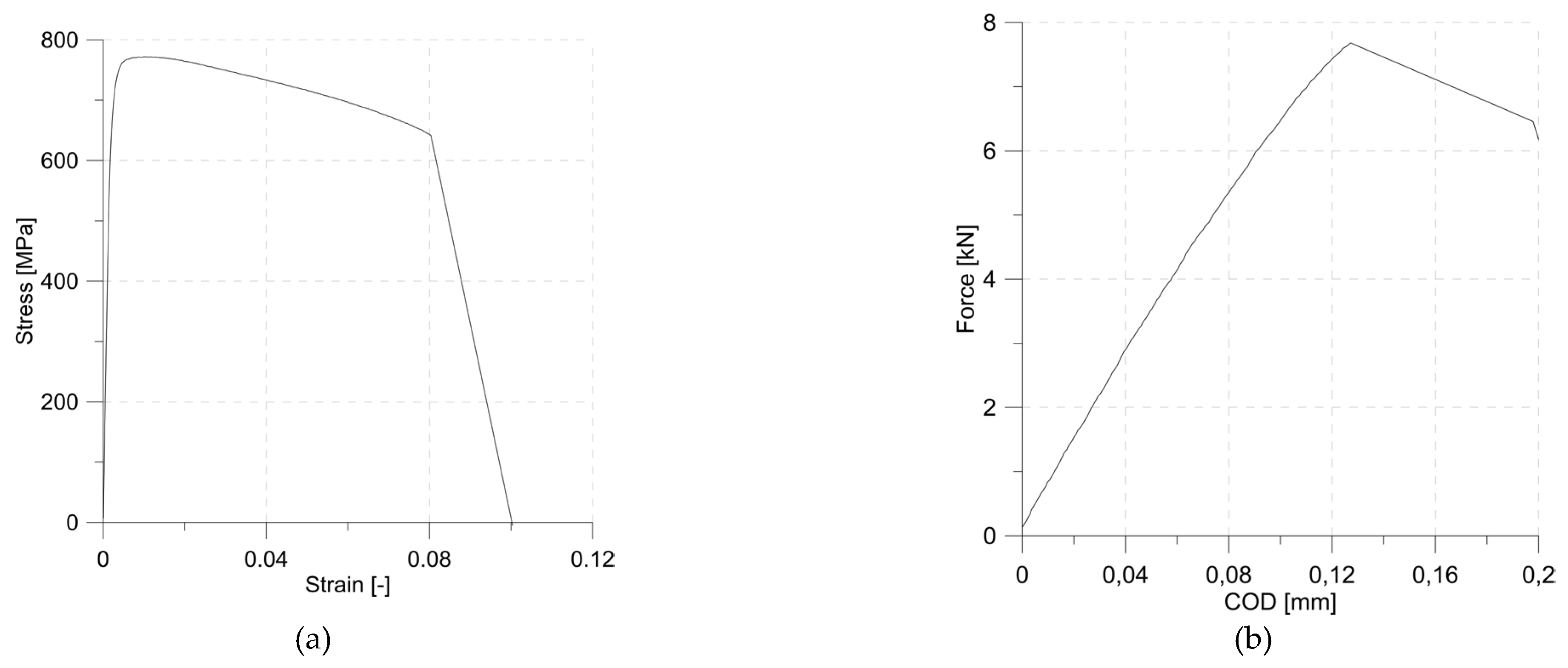
Figure 2.
Geometry of the tested specimens.
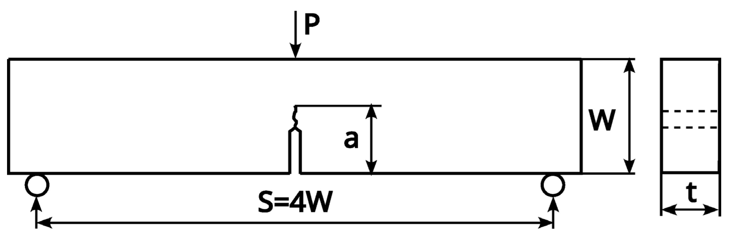
Figure 3.
Details of numerical model: general view of the specimen (top row), area of the plane of symmetry(middle row) and crack tip zone (bottom row).
Figure 3.
Details of numerical model: general view of the specimen (top row), area of the plane of symmetry(middle row) and crack tip zone (bottom row).
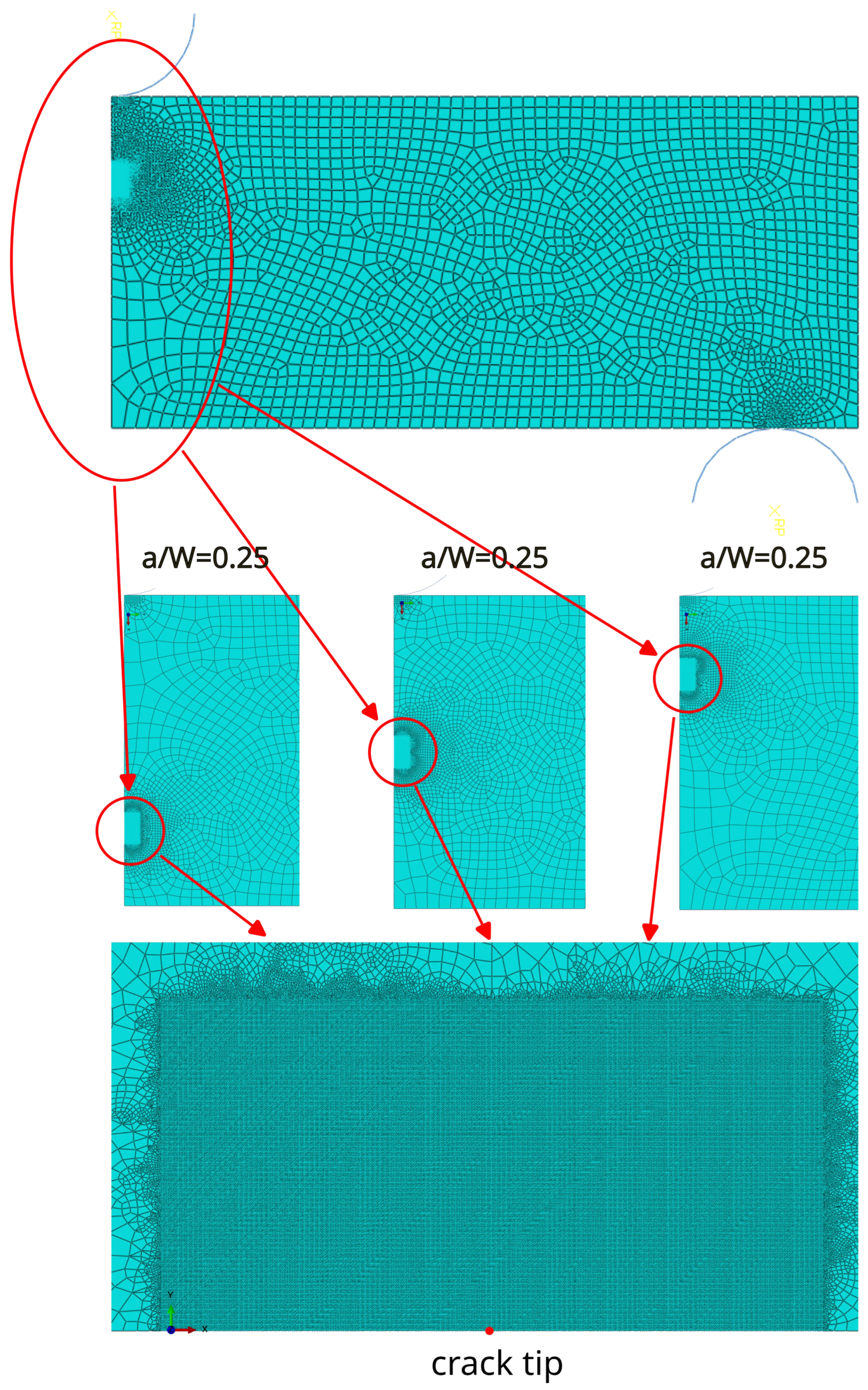
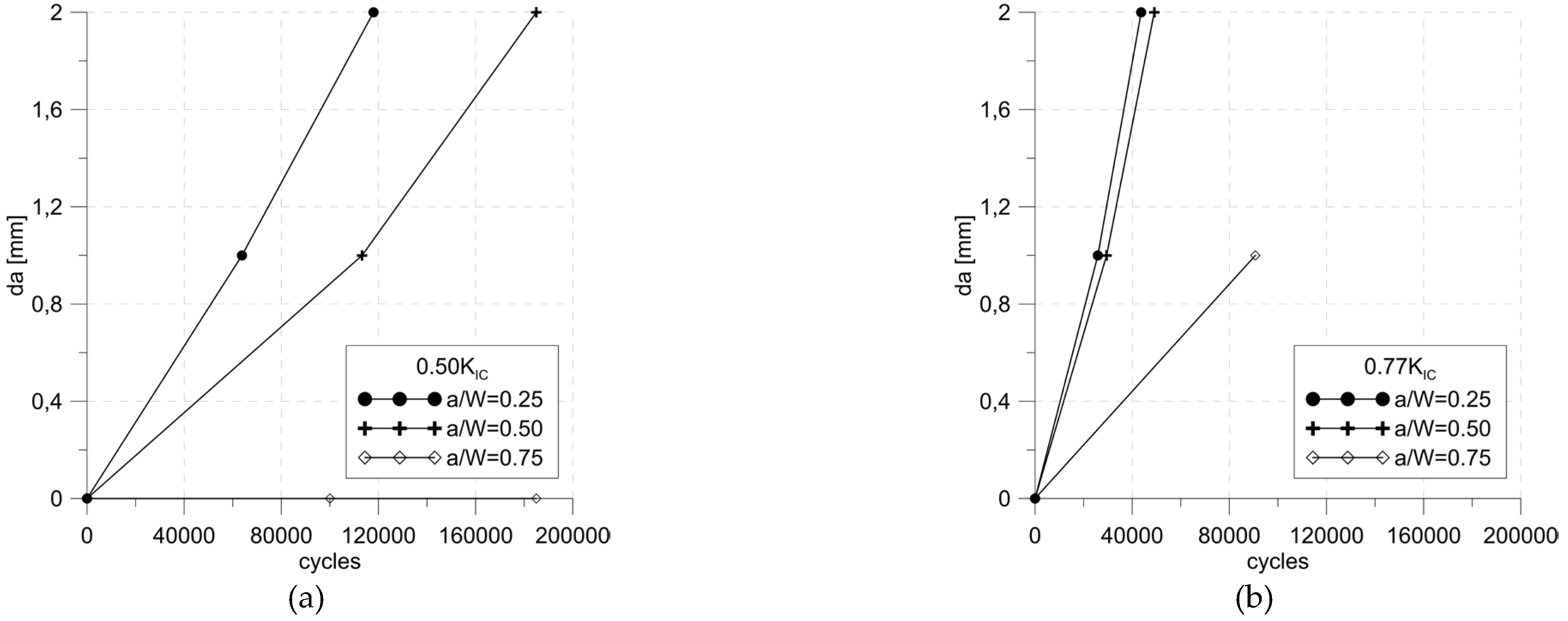
Figure 5.
Mohr’s circles for selected values of T-stress.
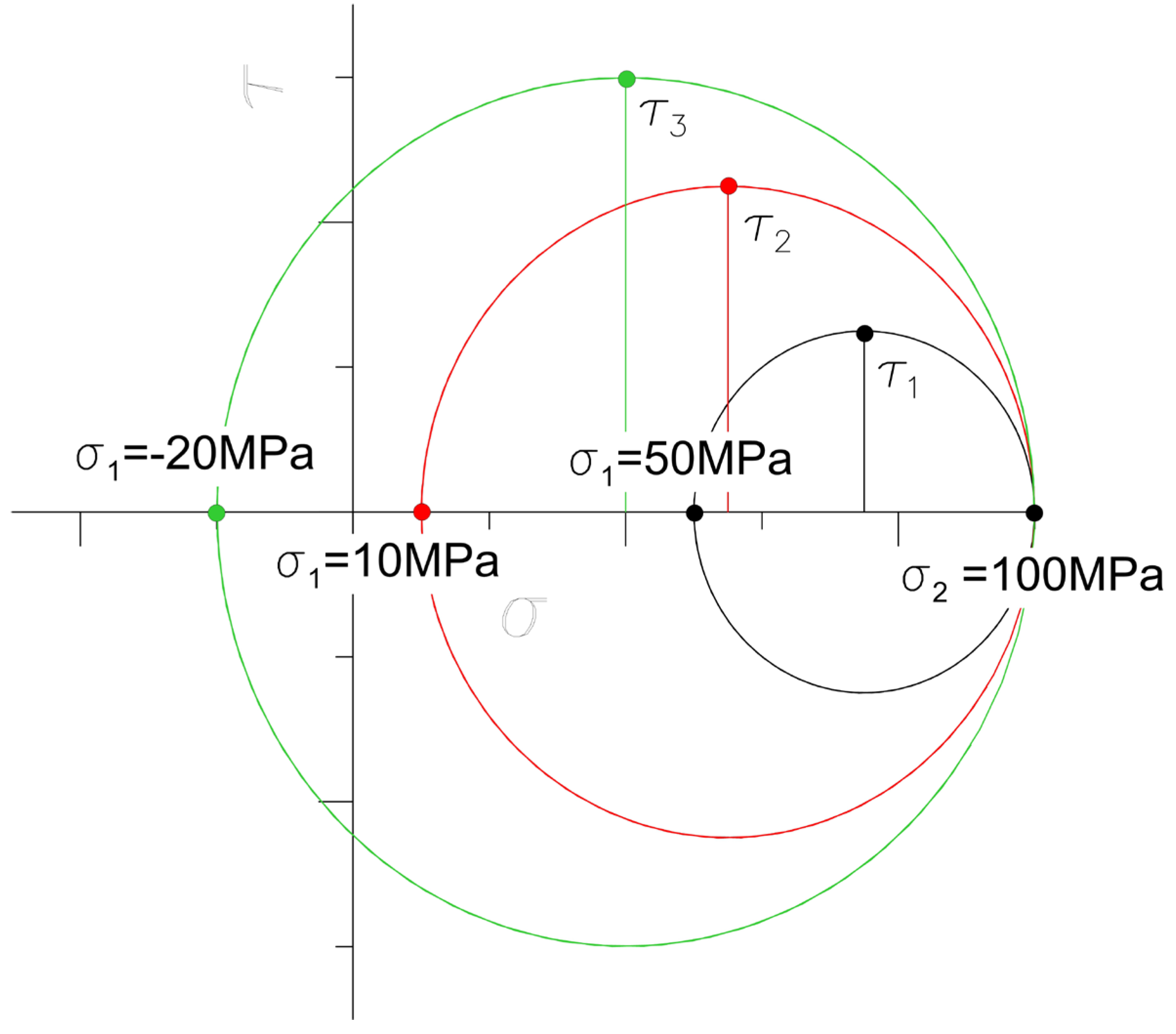

Table 1.
Material parameters.
| Feature | Value |
|---|---|
| Young's modulus [GPa] | 182.9 |
| Yield strength [MPa] | 711.45 |
| Tensile strength [MPa] | 771.61 |
| Elongation [%] | 16 |
| Reduction in area [%] | 64.54 |
Table 2.
Applied loads [N].
| Max. SIF level | a/W=0.25 | a/W=0.5 | a/W=0.75 |
|---|---|---|---|
| 0.5 KIC | 3985 | 2004 | 692 |
| 0.77 KIC | 6161 | 3098 | 1070 |
Table 3.
Number of cycles to achieve 1 mm crack growth.
| Max. SIF level | a/W=0.25 | a/W=0.5 | a/W=0.75 |
|---|---|---|---|
| 0.5 KIC | 63793 | 113274,5 | >1000000 |
| 0.77 KIC | 25855 | 29477,5 | 90706 |
Table 4.
Number of cycles to achieve 2 mm crack growth.
| Max. SIF level | a/W=0.25 | a/W=0.5 | a/W=0.75 |
|---|---|---|---|
| 0.5 KIC | 117969 | 185015 | >1000000 |
| 0.77 KIC | 43713 | 49085 | not conclusive |
Table 5.
T-stress values [MPa].
| Max. SIF level | a/W=0.25 | a/W=0.5 | a/W=0.75 |
|---|---|---|---|
| 0.5 KIC | -38.65 | 19.09 | 67.55 |
| 0.77 KIC | -59.75 | 29.49 | 104.43 |
Table 6.
SIF values for crack length increased by 1 mm [MPa√m].
| a [mm] | F(0.5KIC) | F(0.77KIC) |
|---|---|---|
| 6 | 30,4 | 46,0 |
| 11 | 31,6 | 48,8 |
| 16 | 37,5 | 58,0 |
Table 7.
SIF values for crack length increased by 2 mm [MPa√m].
| a [mm] | F(0.5KIC) | F(0.77KIC) |
|---|---|---|
| 7 | 34,6 | 53,5 |
| 12 | 37,9 | 58,6 |
| 17 | 57,9 | 89,5 |
Table 8.
Crack growth rates in the range 0- 1 mm [mm/cycle].
| Max. SIF level | a/W=0.25 | a/W=0.5 | a/W=0.75 |
|---|---|---|---|
| 0.5 KIC | 1,56757E-05 | 8,82811E-06 | arrested |
| 0.77 KIC | 3,86772E-05 | 3,39242E-05 | 1,10246E-05 |
Table 9.
Crack growth rates in the range 1- 2 mm [mm/cycle].
| Max. SIF level | a/W=0.25 | a/W=0.5 | a/W=0.75 |
|---|---|---|---|
| 0.5 KIC | 1,84584E-05 | 1,39391E-05 | arrested |
| 0.77 KIC | 5,59973E-05 | 5,10009E-05 | not conclusive |
Disclaimer/Publisher’s Note: The statements, opinions and data contained in all publications are solely those of the individual author(s) and contributor(s) and not of MDPI and/or the editor(s). MDPI and/or the editor(s) disclaim responsibility for any injury to people or property resulting from any ideas, methods, instructions or products referred to in the content. |
© 2024 by the authors. Licensee MDPI, Basel, Switzerland. This article is an open access article distributed under the terms and conditions of the Creative Commons Attribution (CC BY) license (http://creativecommons.org/licenses/by/4.0/).
Copyright: This open access article is published under a Creative Commons CC BY 4.0 license, which permit the free download, distribution, and reuse, provided that the author and preprint are cited in any reuse.


