Submitted:
12 September 2024
Posted:
12 September 2024
You are already at the latest version
Abstract
The dynamic development of robotics is affecting people's lives. Flying robots replace pilots and crews in performing dangerous tasks. There are various designs of the above-mentioned robots such as multi-rotors, fixed-wing aircraft, helicopters, among which wing-in-ground (WIG) units can also be distinguished. WIG vehicles, which utilize ground effect to enhance efficiency and stability, share similarities with UAVs in their control and aerodynamic challenges.
The article presented the results of the autopilot test for the NeoX UAV, which have the potential to be utilized in WIG UAVs. The NeoX was developed at the Air Force Institute of Technology as a reconnaissance flying robot and is a tailless mini UAV. It has a characteristic feature which is the flying wing with a small fuselage. The electric engine with the pusher propeller ensures thrust. The tailless airplane has a greater drag-to-lift ratio than a conventional airplane, but this airplane configuration needs a control system that ensures a stable flight. The structure of auto-pilot for the horizontal flight phase (a cruise phase), the climbing, and the descending phase were presented. The authors concentrated on the longitudinal channel of autopilot and showed the recorded results from the flight tests.
The research focused on developing autopilot system that could be adapted for use in WIG craft, which operate with similar aerodynamic principles but require unique control adaptations due to their proximity to the water or ground. The findings from the NeoX UAV tests are instru-mental in enhancing the stability and performance of these specialized crafts, ensuring safer and more efficient operation in their respective environments.
Keywords:
eyword
; autopilot
; wing-in-ground (WIG)
; control system
; drones
; flight tests
; UAV
; RPAS
; autonomous robots
; autonomous systems
; linear systems
; switched systems
1. Introduction
The UAVs are used in military and civilian applications. They realized different tasks from delivering pizzas to attacking tanks and other military systems. Now, soldiers, civil services, and commercial companies have been using different types of UAVs. The construction of UAVs depends on the tasks. If the operators perform high-precision tasks, they frequently use multirotor drones. The flight time, load weight, range of operation, and environment influence the configuration of the UAVs. The basic three configurations of UAVs are being used now. There were mentioned multirotor drones. These drones use a few motors with a propeller to generate aerodynamic forces. They are equipped with more than three electric motors. The control of aerodynamic forces and the angular position of the UAV is made by the change in the angular velocity of the electric motors. These kinds of drones are of small mass and range, but they are characterized by vertical take-off and landing and stable hover. They are popular among hobbyists. The multirotor drones have got electric drives, but authors also know the construction of multirotor drones with gasoline combustion engines.
The next type of drone has a helicopter configuration. Those drones have a rotor and a control system that generates the aerodynamic lift and thrust force. The drones are capable of vertical take-off and landing. The helicopter configuration of drones has a mass close to manned helicopters, so they perform similar tasks.
The third group of drones has an airplane configuration. The drones have wings to generate lift force. The airplane configuration enables the drones to perform similar tasks as manned airplanes. Its masses depend on the type of drone, and they range from kilograms (micro UAVs weigh less than 5 kg) to tons (super heavy UAVs weigh more than 2000 kg). The mass classification applies to all drones. The airplane drone has a greater range and the longest time of flight than a similar multirotor and helicopter drone. This configuration of drones is more popular in the military.
A separate group of UAVs are wing-in-ground (WIGs) aircrafts, also known as screeplanes or ekranoplanes. This type of aircraft represents a unique category of unmanned aerial vehicles (UAVs) that operate just above the surface of the water, using the ground effect. Ground effect is the enhanced lift force acting on a wing that is travelling close to the ground or water surface, commonly less than one wing chord height. The enhanced lift is generated by the greater pressure increase on the undersurface of the wing due to higher deceleration of the air trapped between the ground and wing surfaces. This can be enhanced by lowering the wing flaps, installing fences below the wing tips and adjusting the wing plan geometry.
The challenge of designing a configuration of main hull, lifting wings and stabilizing surfaces to give minimum drag in all the modes from floating, possibly hovering on cushion, through planning, to flying in ground effect has led to a wide range of concepts from different designers. They do nevertheless tend to conform to a number of generic configurations or types. Several of them are known by acronyms. The general name covering all such vehicles is WIG. Other names used are the ekranoplan, flair craft, wing ship, hovering, wing-in-surface-effect ships or WISES, power-augmented wing-in-ground effect craft or PARWIG, dynamic air cushion craft or DACC, dynamic air cushion wing-in-ground effect craft or DACWIG, and the ground effect machine or GEM. [1]
The WIG actually fills the gap between surface-supported craft and free flying aircraft. It has potential for higher transport capacity than an airplane, while operating at much higher speed than typical marine vehicles.
The classic configuration of the airplane includes wings with ailerons and a tail with an elevator and a rudder [2]. The tail has fixed surfaces that generate stabilizing moments in the airplane. The disadvantage of this configuration is the drag forces introduced by the tail of the airplane. The tailless airplane does not have this disadvantage [3].
A flying wing is a tailless airplane that does not have a fuselage. The crew, payload, fuel, and equipment are typically housed inside the main wing structure. The flying wing has a greater lift-to-drag ratio than a classic airplane and it has a smaller radar cross-section, but the flying wing has a problem with the stable flight. The next disadvantage is the thick wing because the payload, fuel, equipment, and crew must be placed in the wing.
The mini UAVs do not have the disadvantages of the manned flying wings. The control system of the UAV ensures a stable flight of airplanes and the equipment is reduced. Moreover, the mini UAV has all the advantages of the flying wing as a greater lift-to-drag ratio and a smaller radar cross-section.
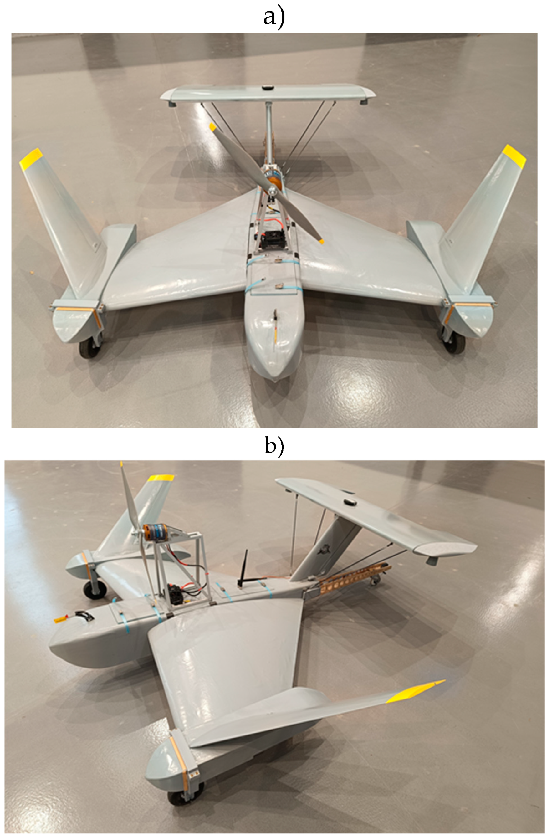
The paper presents the results of the research on the autopilot of the UAV, specifically focusing on the operation range of altitude stabilization. The experience and findings from these tests are presented below and will be used to design the autopilot system for wing-in-ground (WIG) craft. The authors used the NeoX UAV to test the autopilot with new altitude stabilization algorithms. The NeoX UAV was developed at the Air Force Institute of Technology. It is dedicated to reconnaissance missions for the military and the civil service. It is a tailless fixed-wing aircraft with a small fuselage and a pusher propeller. It has a configuration of the flying wing. The AFIT NeoX was presented in Figure 1, and Figure 2. The NeoX has a mass of up to 11 kg, a speed of 50÷170 km/h, altitude of 100÷1000 m, max. the altitude of 4000 m, operation range of 10÷30 km, and operation time of 90÷120 min. It can operate with different payloads.
The flying wing airplane has a trend to drop the nose which is attributed to the relative positions of the center of mass and the center of pressure. [4] The control system of the UAV ensured its stable flight. The article focuses on controlling the longitudinal channel, which influences the change of altitude and airspeed, which in particular cases may cause the plane to stall. There are many approaches [5,6,7,8,9,10] to longitudinal channel control, but two of them should be distinguished. The first is described in [11], where flight phases are divided into climb, descent, and horizontal flight, and the second [12,13,14,15], which assumes control over the change in the potential and kinetic energy, is called the Total Energy Control System (TECS). Given that the NeoX is intended for military applications, it must meet stringent requirements and criteria outlined by the method of designing unmanned aerial vehicles and testing their functionality [16]. Flight safety and maximization of flight time were prioritized in the development of control laws. After the literature analysis, it was decided to choose the first approach because energy algorithms may incorrectly estimate the required energy. Additionally, when using an electric drive it is easy to identify the most economical flight parameters. After the implementation of the algorithms described in [11] and the performance of flight tests [17], several problems were identified while switching flight phases - excessive platform acceleration, the pitch-up effect, and drop-nose. Some of the problems mentioned created dangerous situations. The lack of results in the reviewed literature is likely due to previous tests being conducted on conventional airplanes. For this reason, the control laws had to be modified to meet the assumed criteria.
The authors presented modifications of the control law of the NeoX autopilot. The modification was introduced in the longitudinal channel of the autopilot. The structure of the longitudinal channel and the result of the test in the operation case were also demonstrated. Similar works were conducted with auto diagnostic systems [18] and for manned aviation [19] in the Air Force Institute of Technology, where huge efforts were channeled in the state of the object before, during, and after the mission. What is more, precise height control is needed to obtain high-quality imaging from the head, which has been described in [20] and [21].
2. The Structure of Autopilot
The autopilot of NeoX UAV has different control laws for state horizontal flight (the cruise state) and the climbing or the descending state. All control laws stabilize the altitude and the airspeed of the UAV.
The control law for the cruise state (Figure 3) estimates the altitude error, and it computes the reference vertical speed. The reference vertical speed is limited to ±2,5 m/s (Figure 3). The real vertical speed is filtered by a low passband filter with the cut frequency of 1 Hz (Figure 3). The error vertical speed is the input to a PID controller which computed a reference pitch angle. Next, the error of the pitch angle is the input to a PID controller which computes the elevation angle (Figure 3).
The algorithm of the control altitude (Figure 3) is extremely modified. There, vertical speed to the algorithm of control is introduced. The vertical speed is limited and the measured vertical speed is additionally filtered. All operations reduce the problem of the dropping nose (Figure 3).
The airspeed is controlled by the change in the position of the throttle (Figure 4). The NeoX UAV has an electric motor to generate the thrust. The change in the position of the throttle in the NeoX leads to a change in the percentage of the pulse width modulation (PWM). The percentage of the PWM is limited from 40% to 80% (Figure 4). The value of PWM is computed by controller PID. The input of the controller is the airspeed error. The algorithm takes into account the constant reference speed as a point of work to control the airspeed. There is the feedforward coefficient (Figure 4) for constant position throttle (value PWM).
The algorithm from Figure 3 and Figure 4 is used in the cruise state. The controller stabilizes the reference altitude. If the NeoX UAV changes the reference altitude, the autopilot will change the algorithm of the control law (Figure 5 ). The reference airspeed is controlled by the change in the pitch angle in this state. The airspeed error is the input to the PID controller. The controller computes the reference pitch angle. Next, the reference pitch angle and measure pitch angle are used to compute the elevation angle by the PID controller (Figure 5).
The altitude is changed by the PWM. When the airplane climbs maximally fast, the autopilot changes the altitude and the PWM has the maximal value (80%). The PWM has a value of 40% when the airplane descends to the reference altitude (Figure 5). When the PWM is equal to 40%, the electric motor does not rotate, and the engine does not generate thrust. The NeoX glides to the reference altitude. The speed is controlled by changing the pitch angle (Figure 5). If the pitch angle grows, the drag force grows too, and the speed is reduced.
The descending or climbing state is automatically changed to a cruise state when the measured altitude is equal to about 80% of the reference altitude. The point of the changing state limits the overshot of the altitude around the reference altitude (Figure 5). The algorithm control of altitude in the cruise state is softer than the algorithm in the descending and climbing state and it does not generate overshot and oscillation.
3. Test Results in the Operational Conditions
The control system of UAV NeoX has been tested in operational conditions. The flight profile is illustrated in Figure 6. The flight profile has five phases. The first is a take-off and the last is a landing of UAV. However, we are going to focus on a climbing, a descending, and a horizontal flight (a cruise). The climbing and descending phases are characterized by the change in the altitude. The altitude is stabilized in the cruise phase and it is corrected relative to the reference altitude. The flight phases are identified by the recorded parameter “Flight phases”. It takes three values “0 – the cruise”, “1 – the climbing” and “-1 – the descending”. The flight phases are shown in Figure 6
The next parameter of flight is an airspeed. The term defining the speed of an aircraft (UAV) relative to the air and it ensures the lift force generated by the wings. The airspeed of UAV was recorded during the test illustrated in Figure 7.
The analysis of the flight has been reduced to the section of flight (Figure 3). This section presents all characteristics of the flight phases except for the take-off and landing.
A. The Horizontal Flight – the Flight Phase “0”
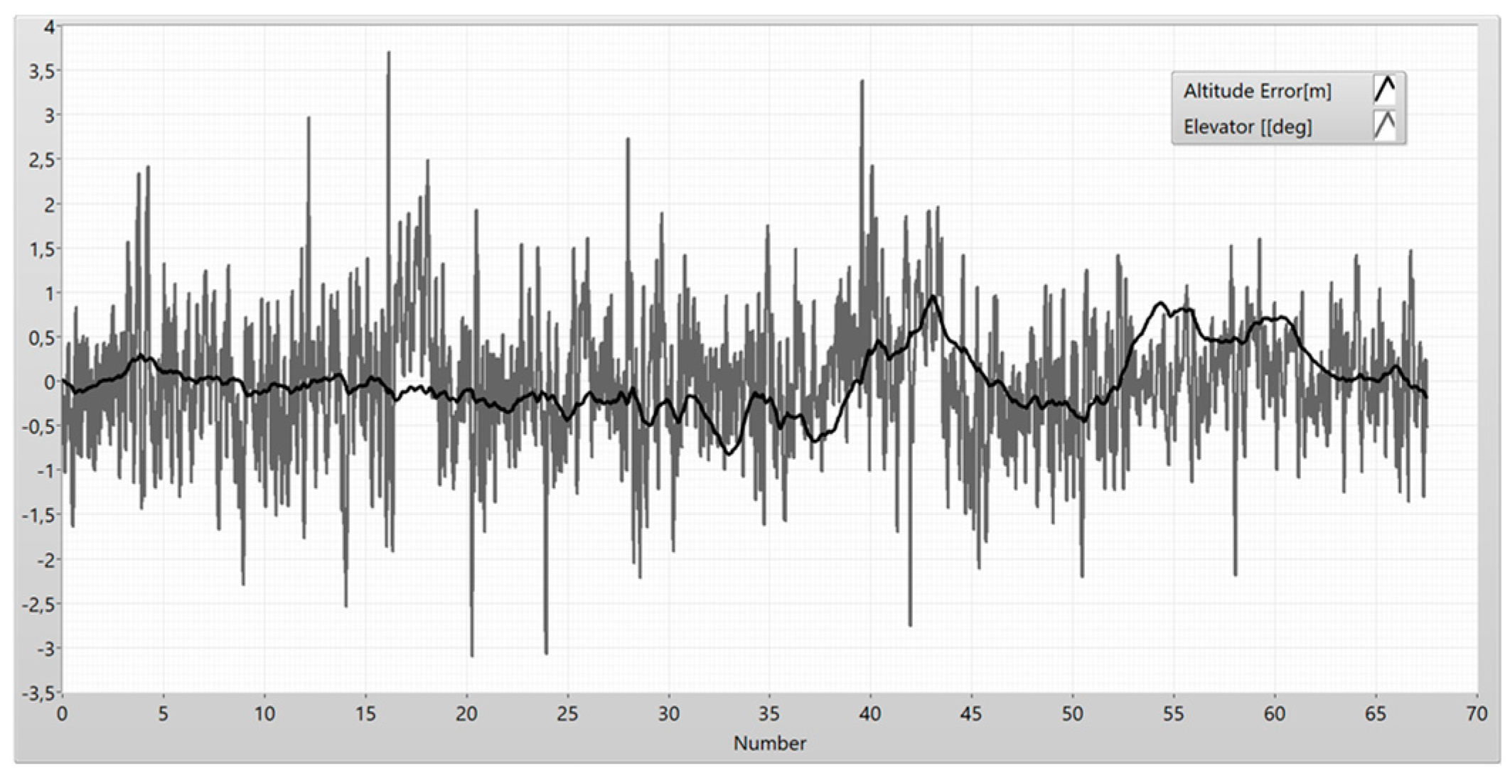
The altitude is controlled by the change in the angular position of the elevator. The angular position of the elevator is the altitude error, which is a result of subtraction between the reference altitude and the measured altitude by the UAV sensors. The dependency between the elevator angular position and the altitude error is shown in Figure 9. The elevator corrects the altitude level. If the elevator goes up, the altitude will grow too. The elevator shows high sensitivity for a disturbance with a frequency greater than 1 [Hz]. This is due to the influence of the differential part of the PID controllers. The passband of the elevator is greater than the passband of the altitude error (Figure 10). The elevator shows small sensitivity for the low-frequency disturbance of the reference altitude (Figure 10). The elevator filtered and eliminated high-frequency. The result of the filtering is presented in Figure 11.
Figure 5.
Position of the elevator and the altitude error.
The control algorithm of stabilization reference altitude has two controllers PID. The first controller generates a reference pitch as a function of the altitude error and the vertical speed. The next controller takes into account the pitch error and generates signals to control the angular position of the elevator.
The dependencies between the angular position of the elevator and the pitch are presented in Figure 12 and Figure 13. The elevator does a faster response for pitch error about low-frequency (Figure 14).
The autopilot corrects the altitude by the changing pitch. When the pitch increases, the drag force increases as well and the speed of the UAV decreases (Figure 10). The autopilot corrects the speed by the change in the thrust force (Figure 11). The speed is corrected by the duty cycle of the PWM in the NeoX UAV. The Pulse Width Modulation signal is used to control revolutions of an electric motor by the motor controller, which is responsible for the distribution of energy by three electric phases. The value of the duty cycle is proportional to the speed error (Figure 12).
Figure 15.
Influence the pitch for the drag force.
Figure 16.
Airspeed, reference airspeed and PWM signal.
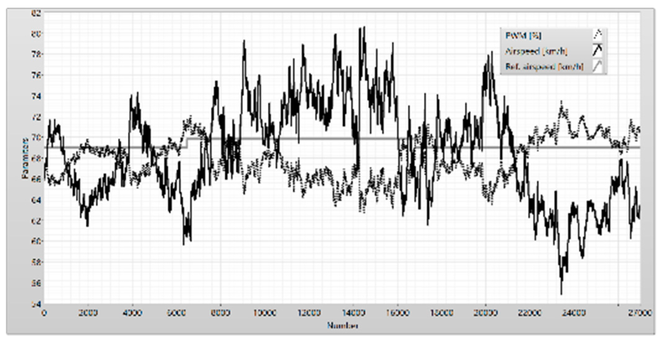
Figure 17.
The duty cycle of PWM and the amplitude error.
B. The horizontal Flight – the Correction of Altitude
Figure 8 shows the correction of the altitude in the cruise phase (flight phase = 0). The operator changed the altitude from 100 m to 115 m and the autopilot corrected the altitude proportional to altitude error. The autopilot remained in the flight phase “0” (Figure 18).
The altitude error and the vertical speed are used by the autopilot to correct the value of reference pitch (Figure 19). The altitude error behaves as a step and the autopilot could have led to a stall. The limitation of the vertical speed reduces the strong increase in the pitch and the angle of attack and protects against the loss of the lift forces. When the altitude error reduces to zero, the vertical speed and reference pitch oscillate around zero too (Figure 19). The autopilot obtained the reference pitch as a reaction for determining a stochastic disturbance. The UAV, as a close system, shows susceptibility to low frequency (the passband to 1 [Hz]). The highest frequencies do not have a significant impact on the dynamics of UAV (Figure 20).
The pitch error (the result of subtraction between the reference pitch and the measured pitch) influences control of the angular position of the elevator. The elevator is tracking changes in the pitch (Figure 21). The PID controller in the autopilot reduces the pitch error. The elevator had a constant for trimming the UAV (Figure 22).
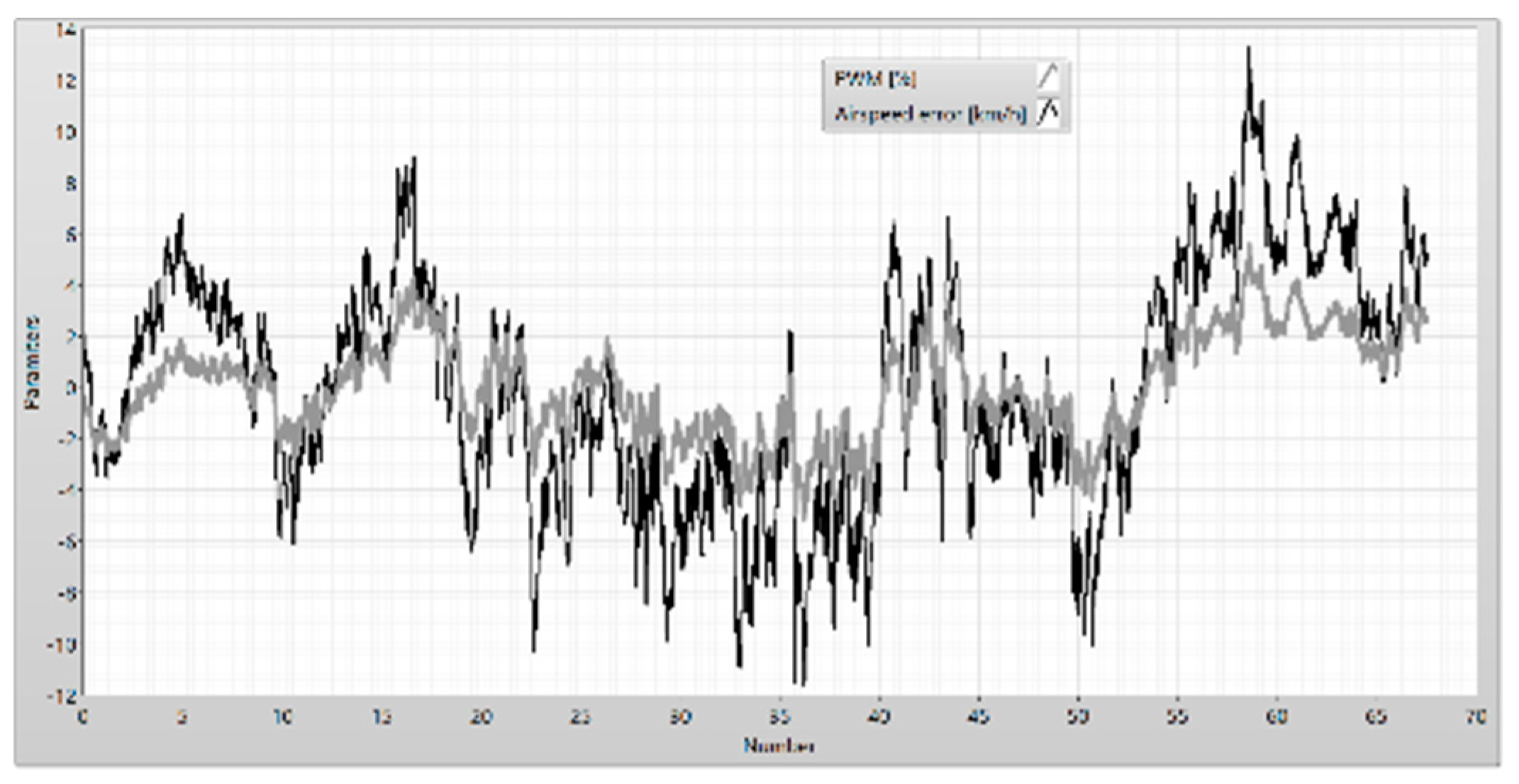
The pitch directs the UAV to the reference altitude. If the pitch grows, the drag grows too and the airspeed is down. The autopilot influences the airspeed by the control of the thrust. The PID controller changes the duty cycle of PWM (Figure 23). The PWM signal is proportional to the airspeed (Figure 24.a) and it has the opposite phase (Figure 24.b)
C. Descending of the UAV
When the UAV is descending, the autopilot moves to flight phase - 1 (Figure 25 and Figure 26). The autopilot changes the control laws for the speed and altitude. The altitude is corrected by the change in the thrust of the engine. The autopilot reduces the thrust to zero (the PWM is equal 40%). If the thrust is reduced to zero, the lift forces decrease and the UAV lowers the nose. When the airplane gets an altitude equal to the reference altitude minus 20 m, the autopilot will move to flight phase 0. The next step of altitude correction runs as presented in the cruise state.
When the nose of the UAV lowers, the UAV dives and rapidly changes the altitude. The pitch and vertical speed have a negative value (Figure 27). The speed of the UAV increases too (Figure 28). The control law of autopilot increases the reference pitch, the drag force increases and the speed decreases to the reference speed (Figure 28) by the changes in the airspeed error to zero (Figure 29).
The descending phase finishes when the altitude error has got an absolute value 20 m. The autopilot enters the flight phase zero and the altitude is corrected by the algorithm presented above.
When the autopilot entered to descending phase, the altitude error was equal to -65 m (Figure 30). The descending phase finished when the altitude error was equal to -20 m. The UAV needed about 13,6 [s] for a change in the altitude of about 45 m (Figure 30). The next 20 m were corrected about the next 12 [s] (Figure 30). The operator corrected the reference altitude to 58 m after entering the flight phase zero (Figure 26 and Figure 30) and the reference altitude of the UAV was achieved after 6.53 [s]. The autopilot descending state ensures a fast-changing altitude. The cruise state only corrects the altitude. Finishing of the descending state is when the altitude error is equal to 20 m, and the autopilot moves to the cruise state eliminating oscillations around the reference altitude.
D. Climbing of the UAV
The climbing state is identified by flight phase “1”. If the autopilot moves to a climbing state, the PWM signal will change to 80% and the engine thrust increases (Figure 31). This is an optimal efficiency state for an electric engine of UAV. The climbing state is similar to the descending state, but in this case, the altitude increases. The main goal of this state is to achieve the reference altitude by the UAV, similar to the descending state (Figure 31).
The nose of the UAV raises and the pitch increases too. The drive of the UAV generates the maximal thrust and the vertical speed increases too (Figure 32). The UAV nose slowly drops when the altitude error approaches the reference altitude minus 20 m, and the autopilot changes a flight phase to cruise state (Figure 33). The modification of the control law in the cruise state ensures a soft change in the vertical speed of the UAV (Figure 33).
The climbing state ensures a fast change in altitude (the max thrust) but the airspeed is controlled by the change in the pitch. The pitch error is presented in Figure 35. It has the oscillation of the pitch error (Figure 35). The airspeed shows the oscillation too (Figure 34). The oscillation of the airspeed error and the oscillation of the pitch error have the opposite phase (Figure 36). If the airspeed is greater than the reference speed, then the airspeed error has the minus sign. The autopilot decreases airspeed by changing the pitch angle (changing the orientation of the UAV). If the pitch increases (Figure 35), the drag force is increased and the airspeed decreases (Figure 34).
5. Conclusions
The paper presents the result of research on the altitude stabilization system of the wing-in-ground class UAV. The control system of the UAV NeoX has been rigorously tested under operational conditions, demonstrating its capability to manage different flight phases, including climbing, descending, and horizontal flight (cruise). The NeoX UAV’s autopilot system effectively manages altitude control during cruise, climbing, and descending phases. The system uses PID controllers to stabilize the altitude, with the elevator’s angular position being a critical factor in correcting altitude errors. The high sensitivity of the elevator to disturbances is managed through filtering, which eliminates high-frequency noise and ensures stable flight. The autopilot system successfully maintains airspeed by adjusting the thrust force. This control mechanism ensures that the UAV maintains the necessary lift force generated by its wings, adapting to changes in pitch and altitude. The NeoX UAV’s autopilot system demonstrates smooth transitions between different flight phases. The first is a cruise state. The autopilot stabilizes the altitude by the change in the pitch angle of the UAV and the speed is controlled by thrust generated by the UAV’s drive. The next states of the autopilot introduce control laws for climbing and descending of the UAV. In those states, the autopilot changes the procedure from stabilizing the altitude to tracking altitude to reference altitude. The engine generates the maximal thrust (80% of PWM) in the climbing state and the airplane rapidly changes the altitude. This is possible because the electric motor has a power reserve. Moreover, the optimal point of work of the electric drive of the UAV is for PWM value from 60 % to 80 %. Climbing or descending states are finished when the altitude error is equal to 20 m. The tracking of the altitude changes the stabilization of the altitude. This approach ensures that the reference altitude is reached softly and it reduces oscillation as well. The descending state works similarly to the climbing state. There is only one difference. The PWM is reduced to 40% and the motor of the UAV stops. The NeoX glides to reference altitude with the maximal vertical speed of 2,5 m/s. The speed is reduced by control drag forces (change in the pitch angle).
The altitude stabilization of the wing-in-ground craft has high expectations. The acceptable deviation of altitude is about 0,2 meters. The craft must stabilize the angular position during take-off. The stabilization of angles pitch and roll is important to generate the lift force which enables to move the craft to the desired altitude. The altitude is controlled by the thrust. If the wing-in-ground craft has the desired altitude it is controlled by a change in an angular position (the pitch angle). The most important element of the developed algorithm was the addition of a cascade connection of the response to the vertical velocity error, which increased time of system response.
The findings from the NeoX UAV tests have significant implications for the development of control systems in wing-in-ground (WIG) effect vehicles. The research indicates that the autopilot systems developed for UAVs can be adapted for WIG craft, which operate under similar aerodynamic principles but require unique control adaptations due to their proximity to the ground. The insights gained from the research not only enhance the UAV’s operational capabilities but also provide a solid foundation for future advancements in UAV and WIG vehicle technologies. The wing-in-ground craft model is presented on the Figure 37.
References
- L. Yun, A. Bliault, i J. Doo, „WIG craft and ekranoplan”, Ground Effect Craft Technology, t. 2, 2010.
- J. Roskam “Airplane flight dynamics and automatic flight controls”, Roskam Aviation and Engineering Corporation, 1979.
- D.G. Hull “Fundamentals of airplane flight mechanics”, Springer-Verlag Berlin Heidelberg, 2007.
- K. Kubryński, R. Nawrocki, “Concept and aerodynamic project of the mini UAV WIZJER”, Air Force Institute of Technology, Warsaw, Poland, 2019.
- M. M. Basson, Stall prevention control of fixed-wing unmanned aerial vehicles, Masters Dissertation, University of Stellenbosch, 2010.
- M. Sadraey, “Unmanned Aircraft Design: A Review of Fundamentals”, Morgan & Claypool Publishers, 2017. [CrossRef]
- M. Sadraey, “Automatic Flight Control Systems”, Morgan & Claypool Publishers, 2020.
- I. Rosario-Gabriel, H. Rodríguez Cortés, “Aircraft Longitudinal Control based on the Lanchester’s Phugoid Dynamics Model”, Unmanned Aircraft Systems (ICUAS) 2018 International Conference on, pp. 924-929, 2018.
- A. Fekih and S.R. Seelem. A fault tolerant control design for automatic steering control of ground vehicles. In 2012 IEEE International Conference on Control Applications (CCA), 2012.
- Gamal Elnagar, Mohammad A. Kazemi, and Mohsen Razzaghi. The pseudospectral Legendre method for discretizing optimal control problems. IEEE Transactions on Automatic Control, 1995. [CrossRef]
- J. D. Barton, “Fundamentals of small unmanned Aircraft Flight”, Johns Hopkins APL Technical Digest, Volume 31, Number 2, 2012.
- Rolando Cortés-Martínez, Hugo Rodríguez-Cortés, “A Total Energy Attitude Control System Strategy for Rigid Spacecraft”, Access IEEE, vol. 7, pp. 112996-113004, 2019. [CrossRef]
- Matthew E. Argyle, Randal W. Beard ”Nonlinear Total Energy Control for the Longitudinal dynamics of an aircraft”, American Control Conference (ACC), 2016.
- Francois Bateman, Hassan Noura, and Mustapha Ouladsine. Actuators fault diagnosis and tolerant control for an unmanned aerial vehicle. In Control Applications. CCA 2007.
- D.R. Gaum, Aggressive Flight Control Techniques for a Fixed-Wing Unmanned Aerial Vehicle, University of Stellenbosch, 2009.
- T. Górski i W. Stecz, „A Method for Modeling and Testing Near-Real-Time System Scenarios”, Applied Sciences, t. 14, nr 5, s. 2023, 2024. [CrossRef]
- M. Chodnicki, J. Głazowski, „Preparation of control system functional tests”, Air Force Institute of Technology, Warsaw, Poland, Tech. Rep. SP-19/58/2020 , 2020. [CrossRef]
- M. Żokowski, K. Falkowski, M. Chodnicki, M. Mazur, M. Witoś, Self-diagnostic system for mini UAV, New Trends in Aviation Development, 2019. [CrossRef]
- 8875542.
- M. Żokowski, M. Witoś, J. Spychała, P. Majewski, Structure Health Monitoring of Aircraft Power Unit Using Vibration Signal, Algorithms and Complexity in Mathematics, Epistemology, and Science, 2019. [CrossRef]
- W. Stecz, K. Gromada Determining UAV Flight Trajectory for Target Recognition Using EO/IR and SAR. Sensors 2020, 20, 5712. [CrossRef]
- W. Stecz, K. Gromada UAV Mission Planning with SAR Application. Sensors 2020, 20, 1080. [CrossRef]
Figure 1.
The NeoX was made by ITWL in flight.
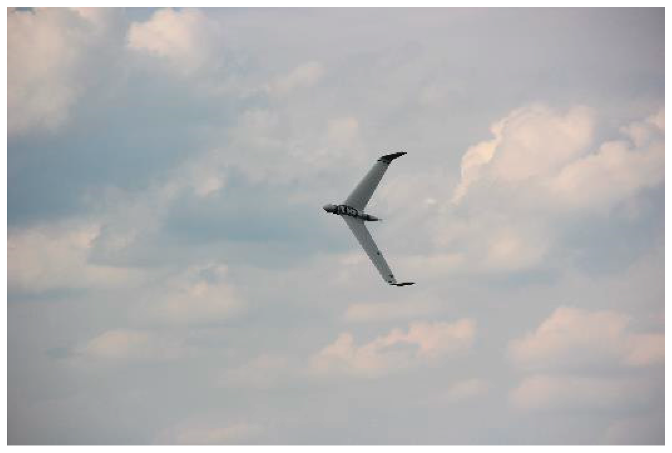
Figure 2.
The UAV NeoX before take-off.
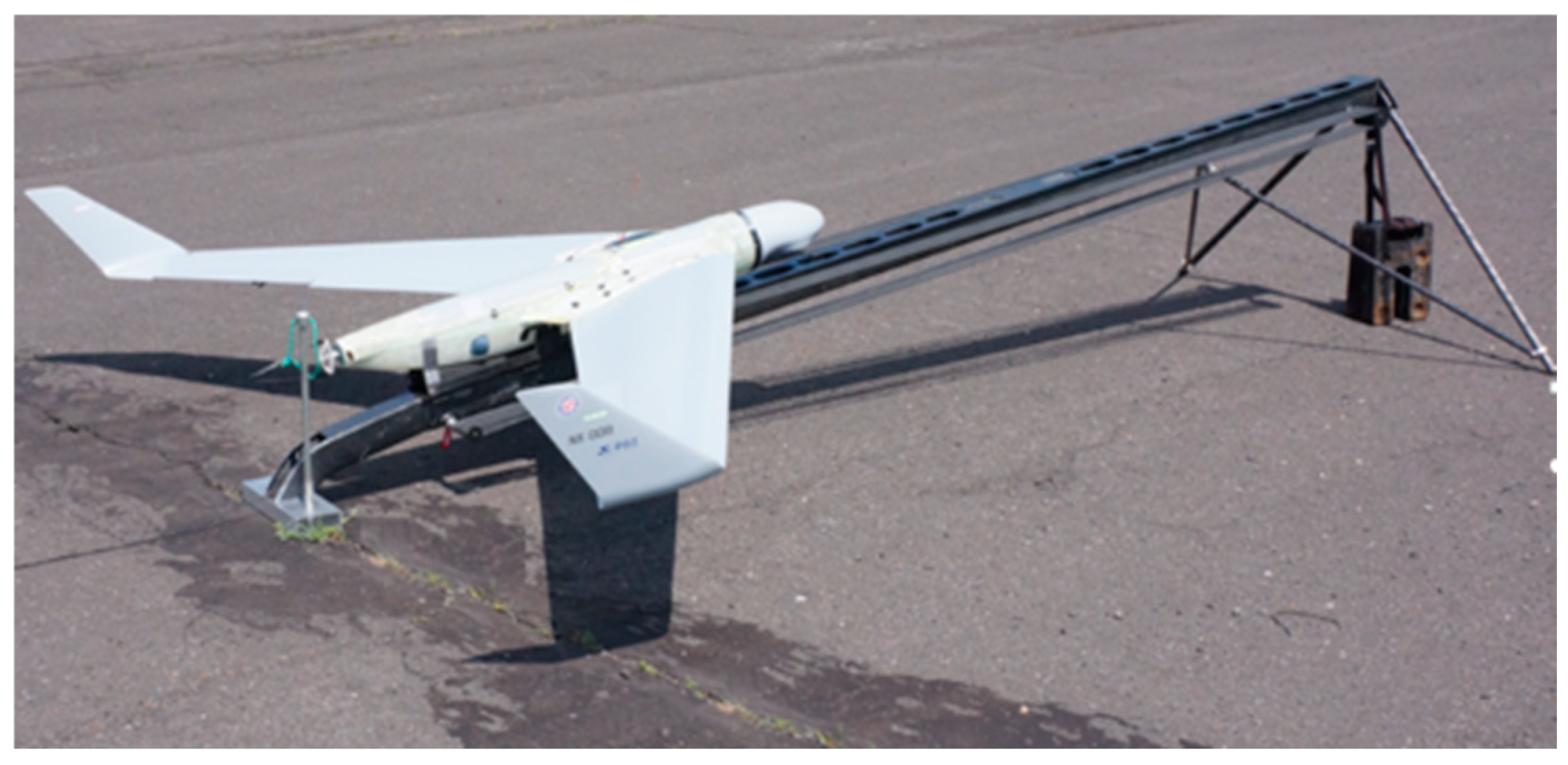
Figure 3.
The diagram control system for stabilizing the airspeed in the cruise state of the autopilot.
Figure 3.
The diagram control system for stabilizing the airspeed in the cruise state of the autopilot.
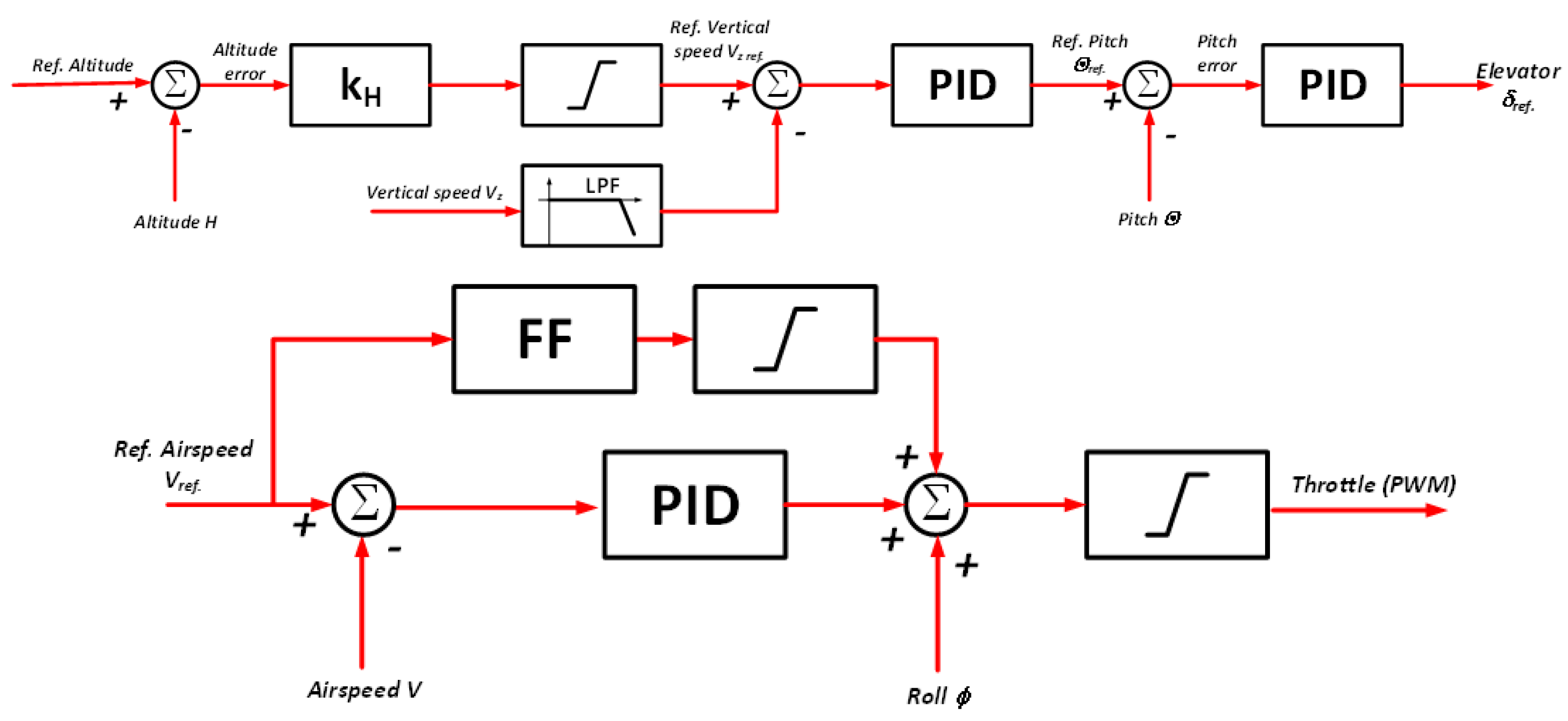
Figure 4.
The segment of the flight profile.
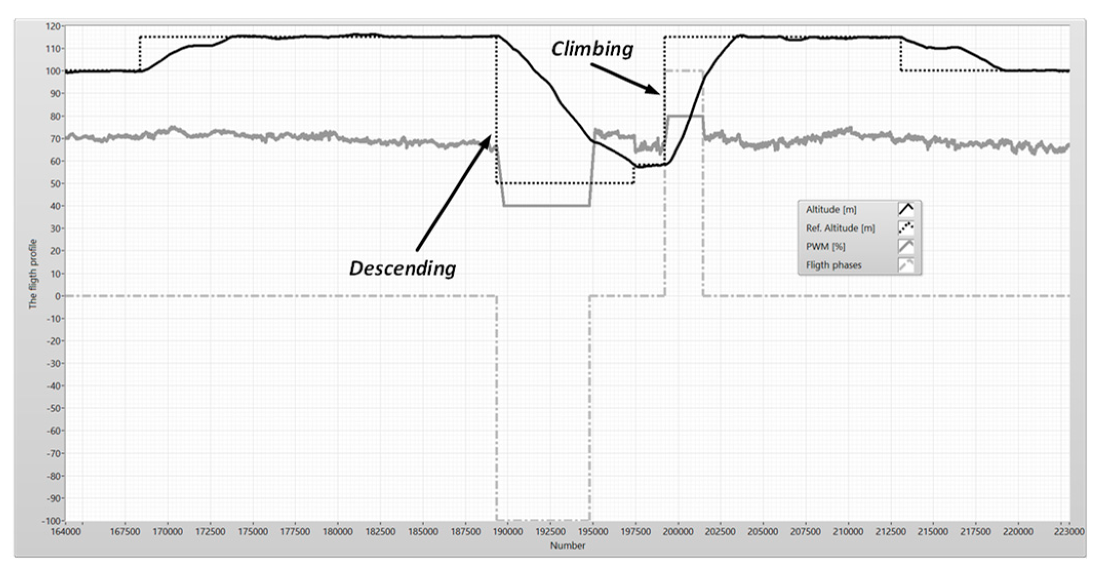
Figure 5.
The diagram control system for stabilizing the speed in the climbing or the descending state of the autopilot.
Figure 5.
The diagram control system for stabilizing the speed in the climbing or the descending state of the autopilot.
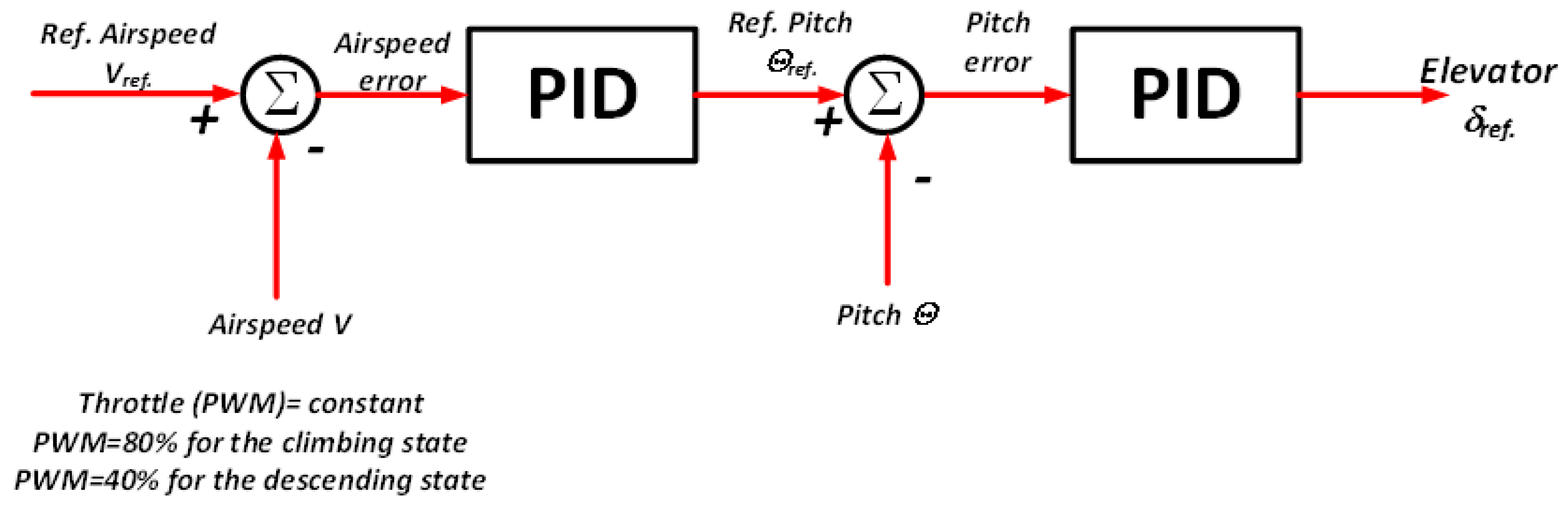
Figure 6.
The flight phases – the altitude.
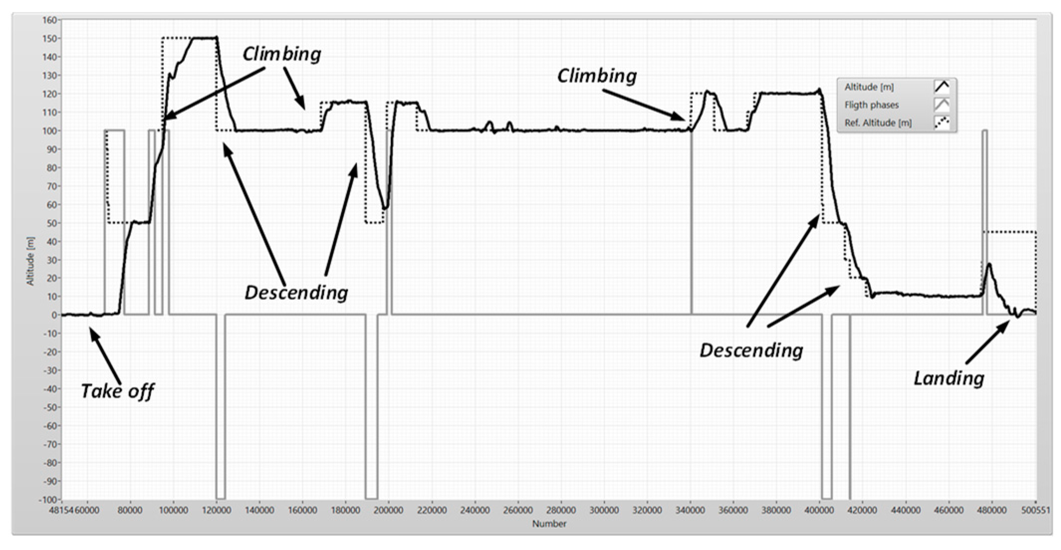
Figure 7.
The flight phases - the airspeed.
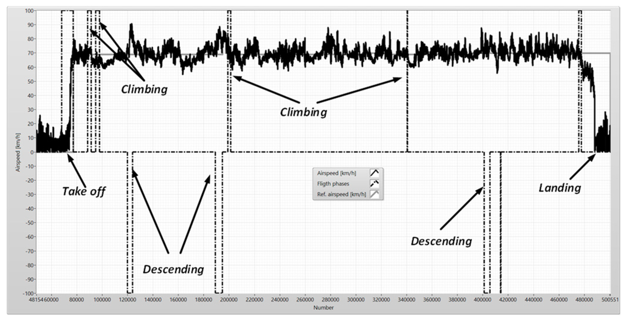
Figure 10.
Frequency analysis of the altitude error and elevator.
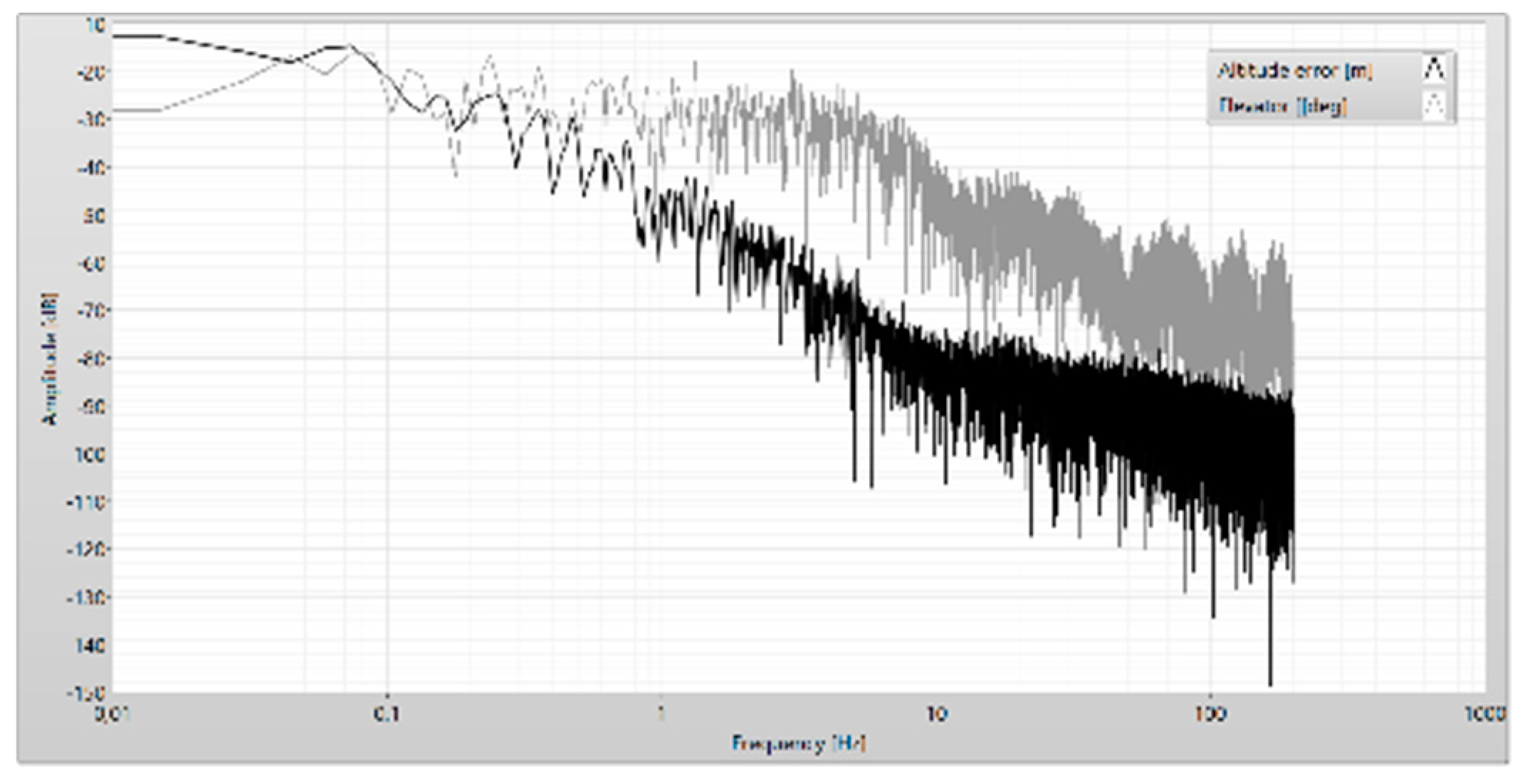
Figure 11.
The position of the elevator after filtering.
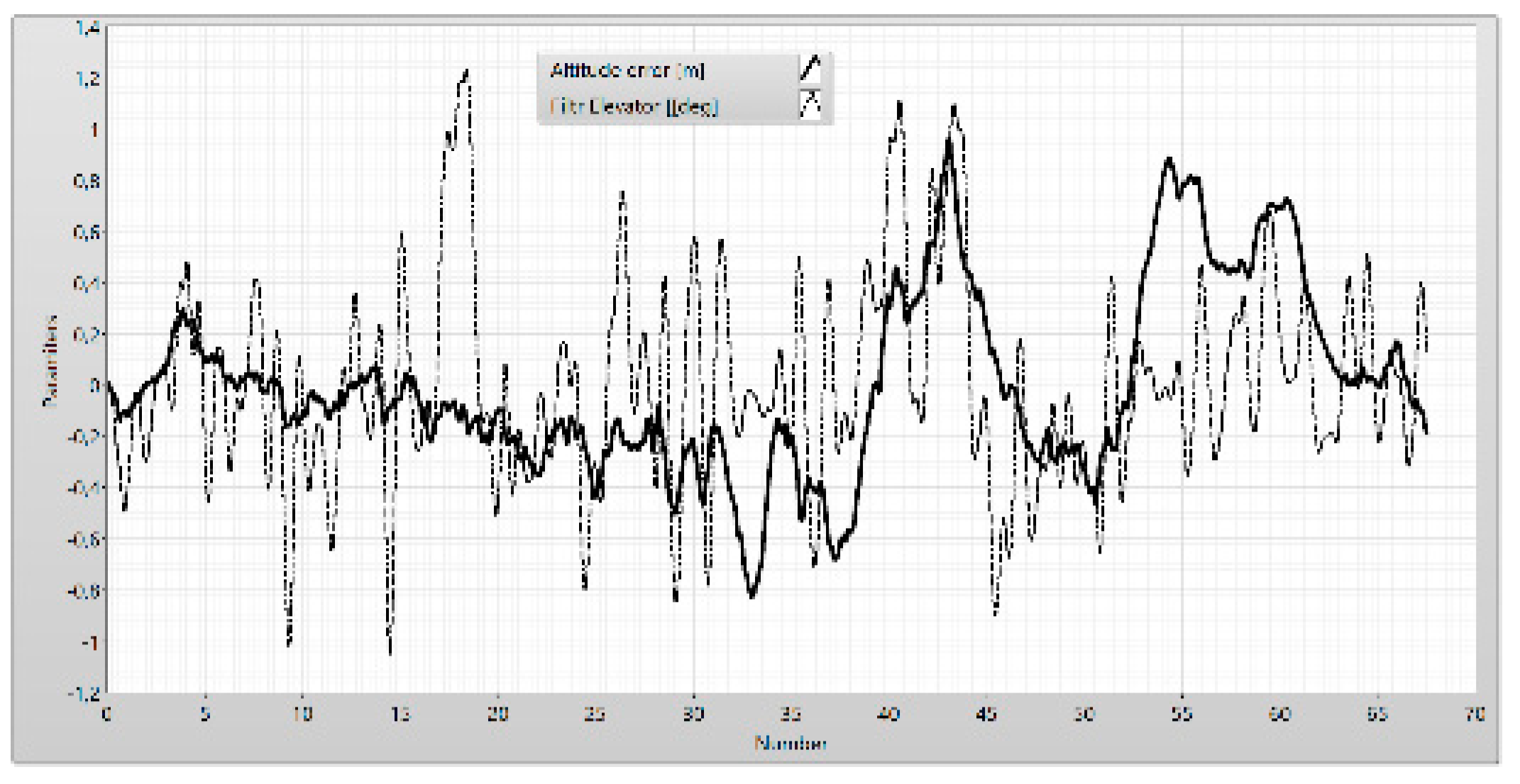
Figure 12.
The reference pitch proportional to the altitude error and the vertical speed of UAV.
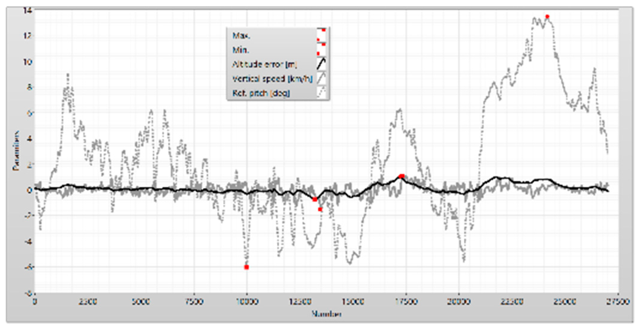
Figure 13.
The position of the elevator to the pitch error.
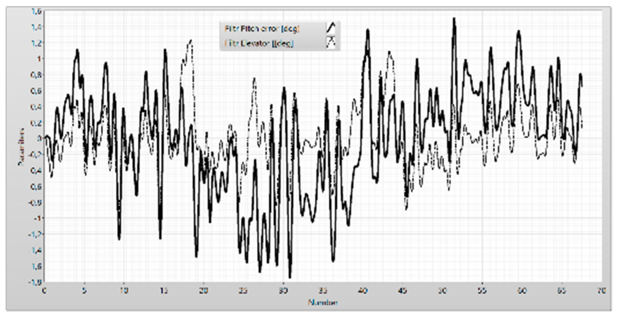
Figure 14.
The frequency analysis of the pitch error and the elevator.
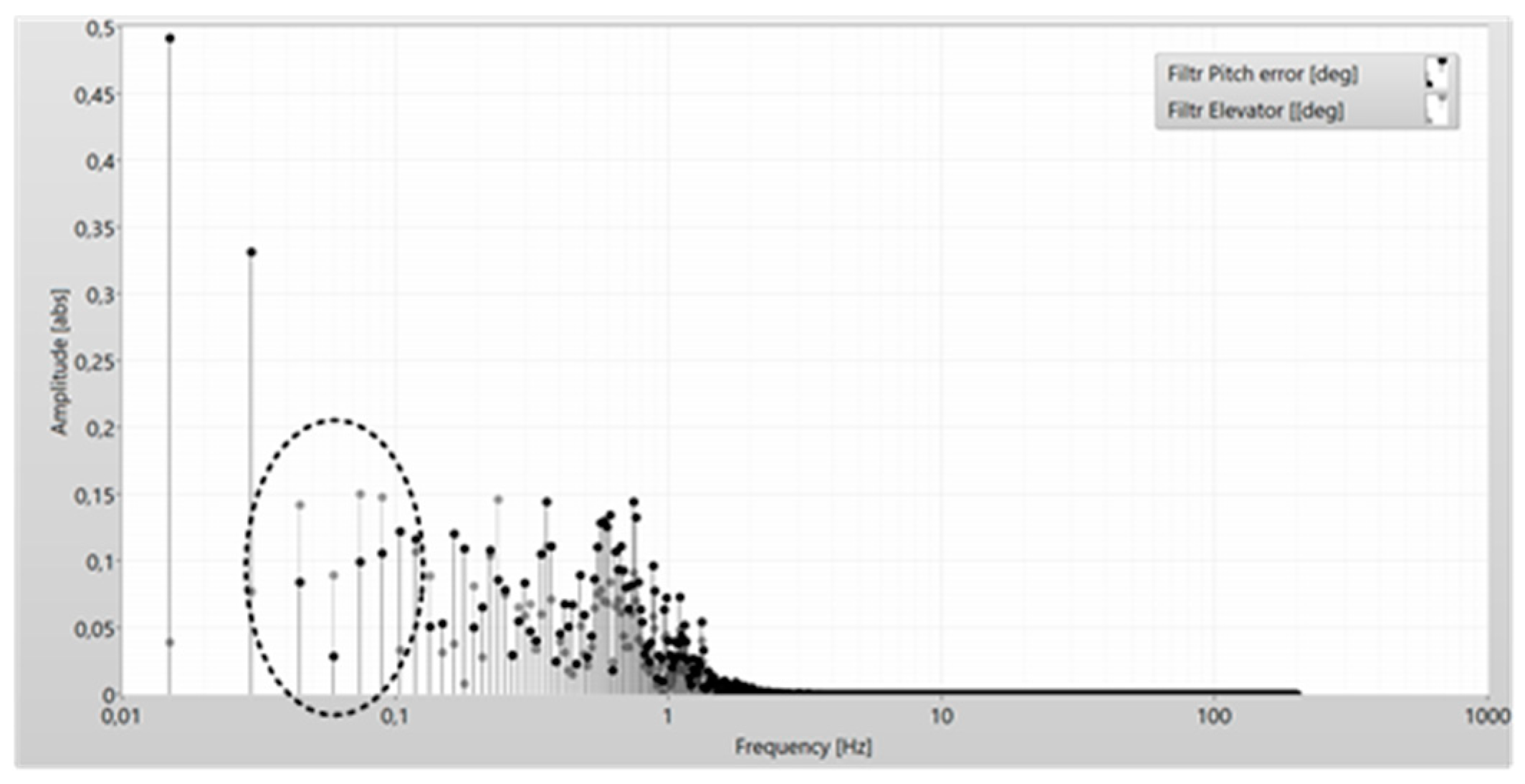
Figure 18.
The correct of the altitude.
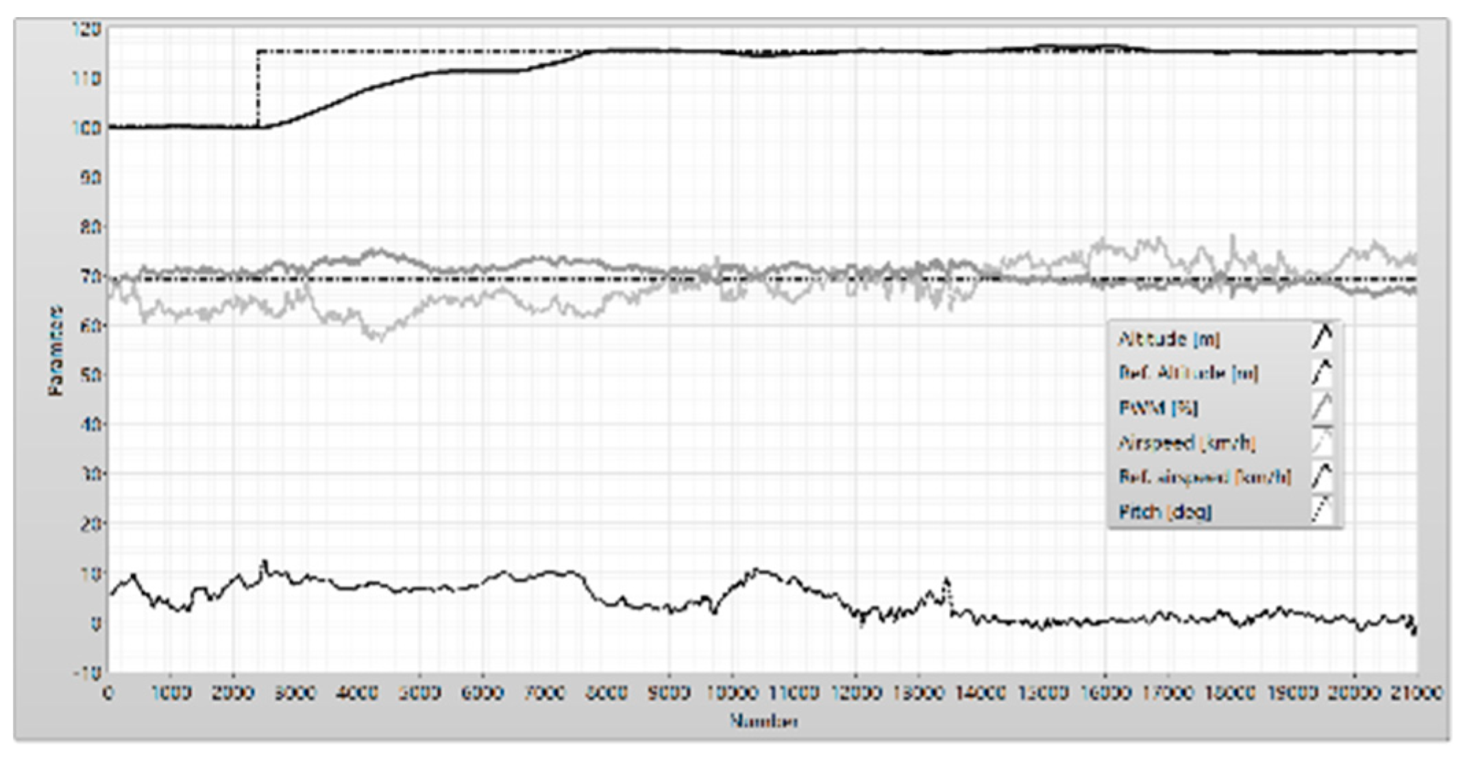
Figure 19.
The reference pitch, the vertical speed, and the altitude error.
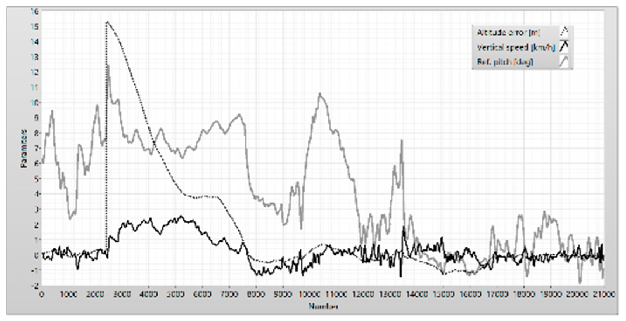
Figure 20.
Frequency analysis parameters.
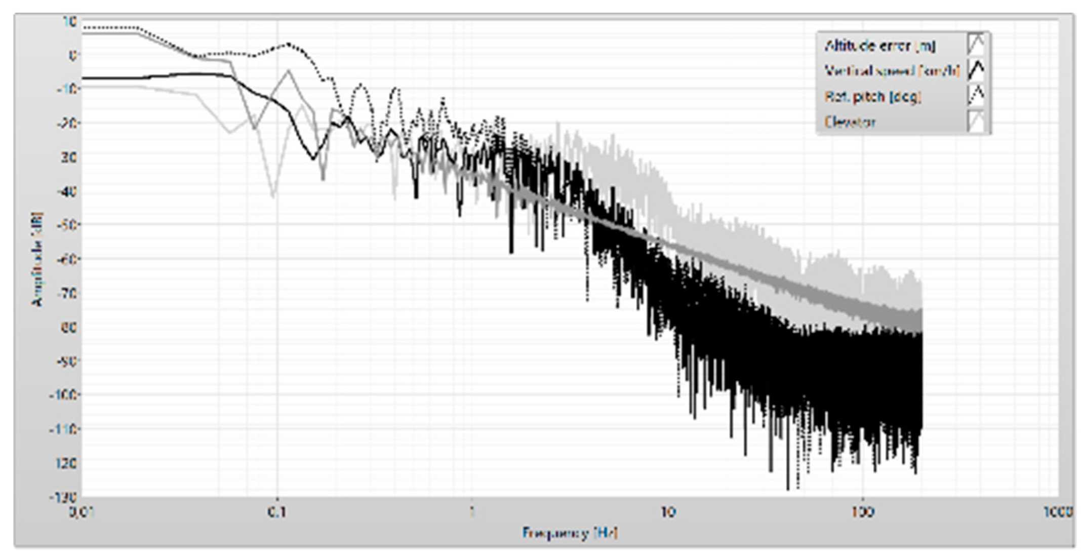
Figure 21.
The elevator and the pitch error.
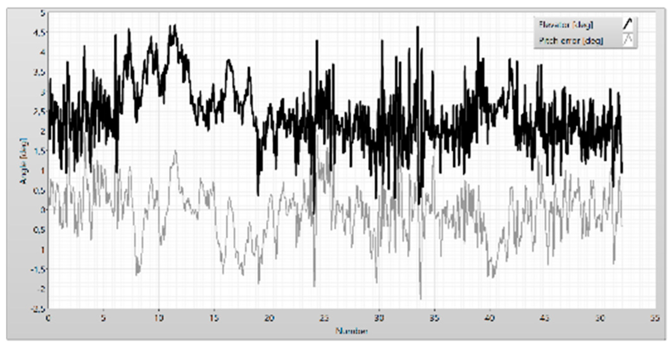
Figure 22.
Histogram of the elevator and pitch error.
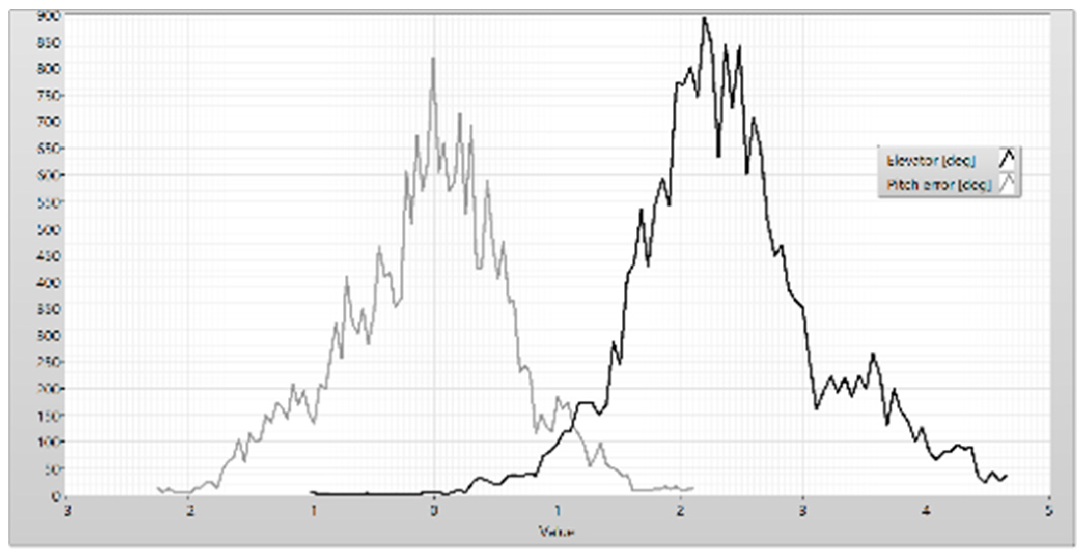
Figure 23.
The airspeed and the duty cycle of PWM.
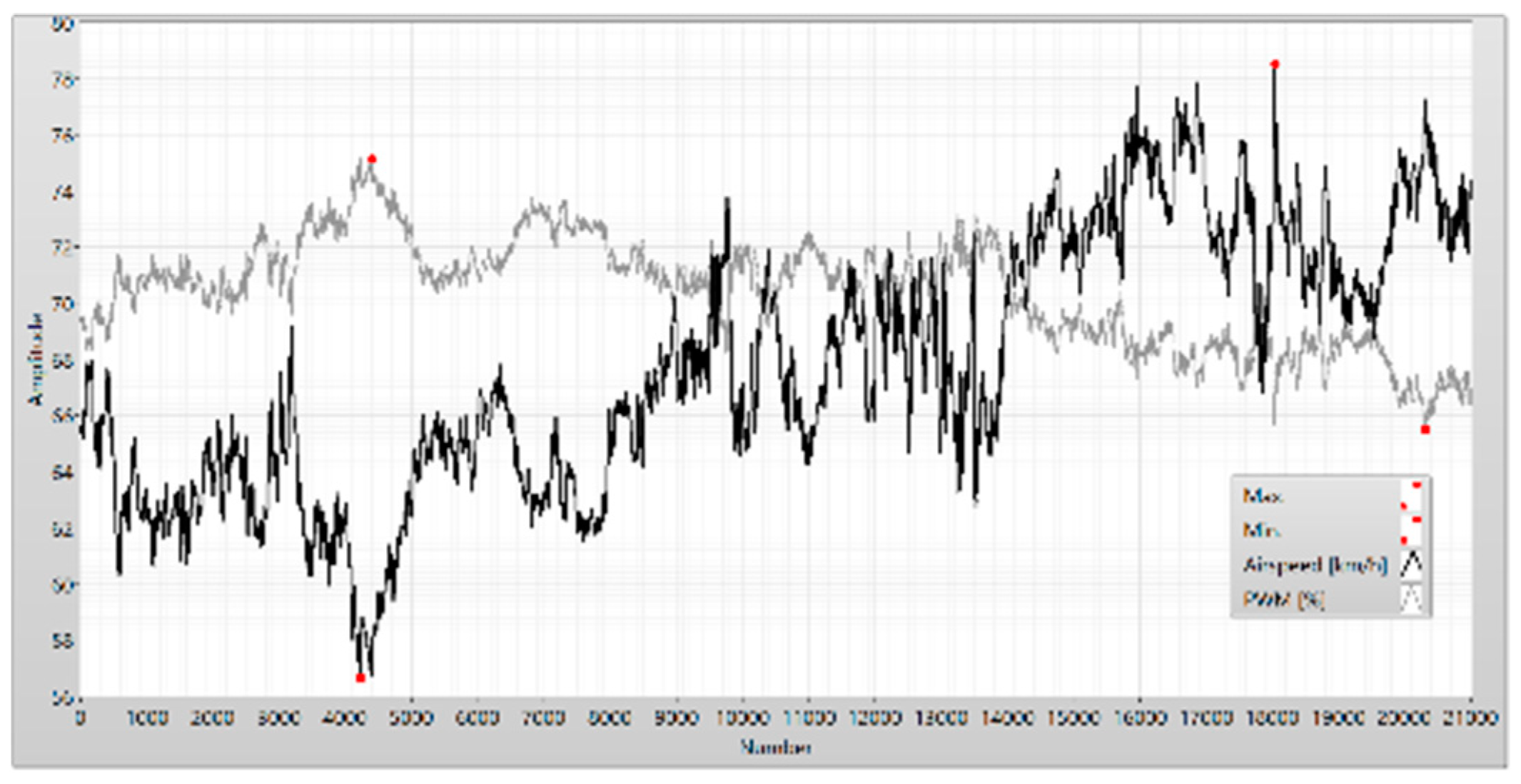
Figure 24.
Amplitude (a) and phase (b) of the PWM and the airspeed.
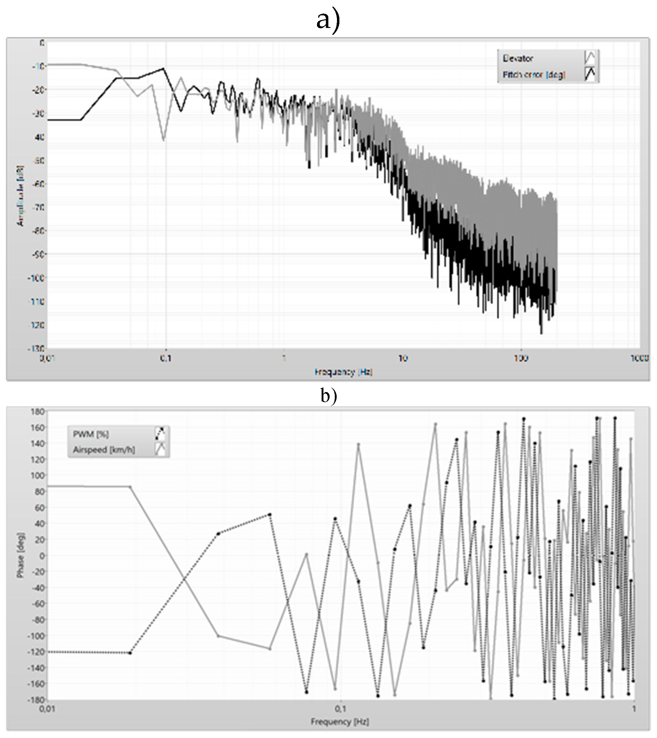
Figure 25.
The parameter of flight in the phases “descending” and “climbing”.
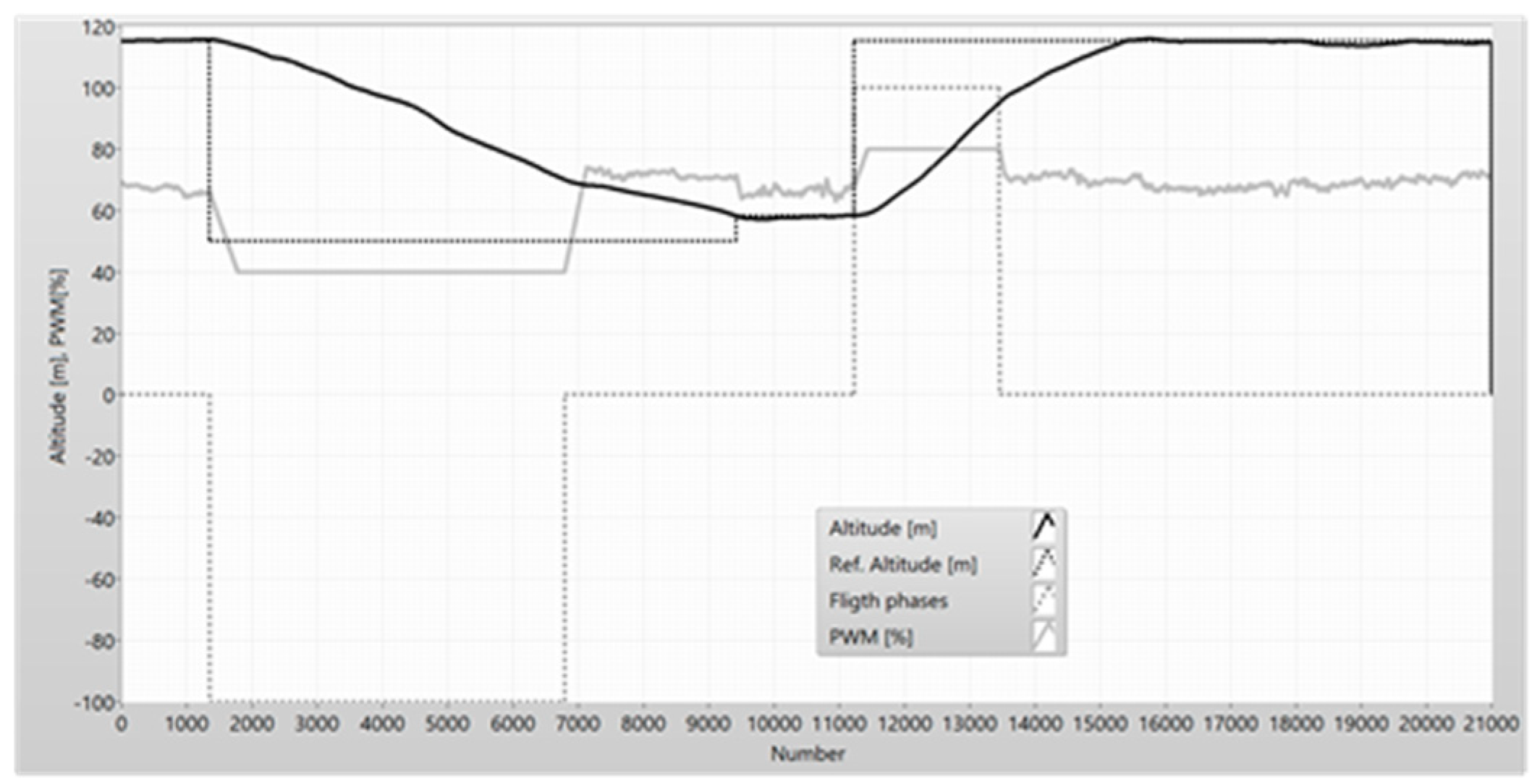
Figure 26.
The altitude and PWM in the descending state of the UAV.
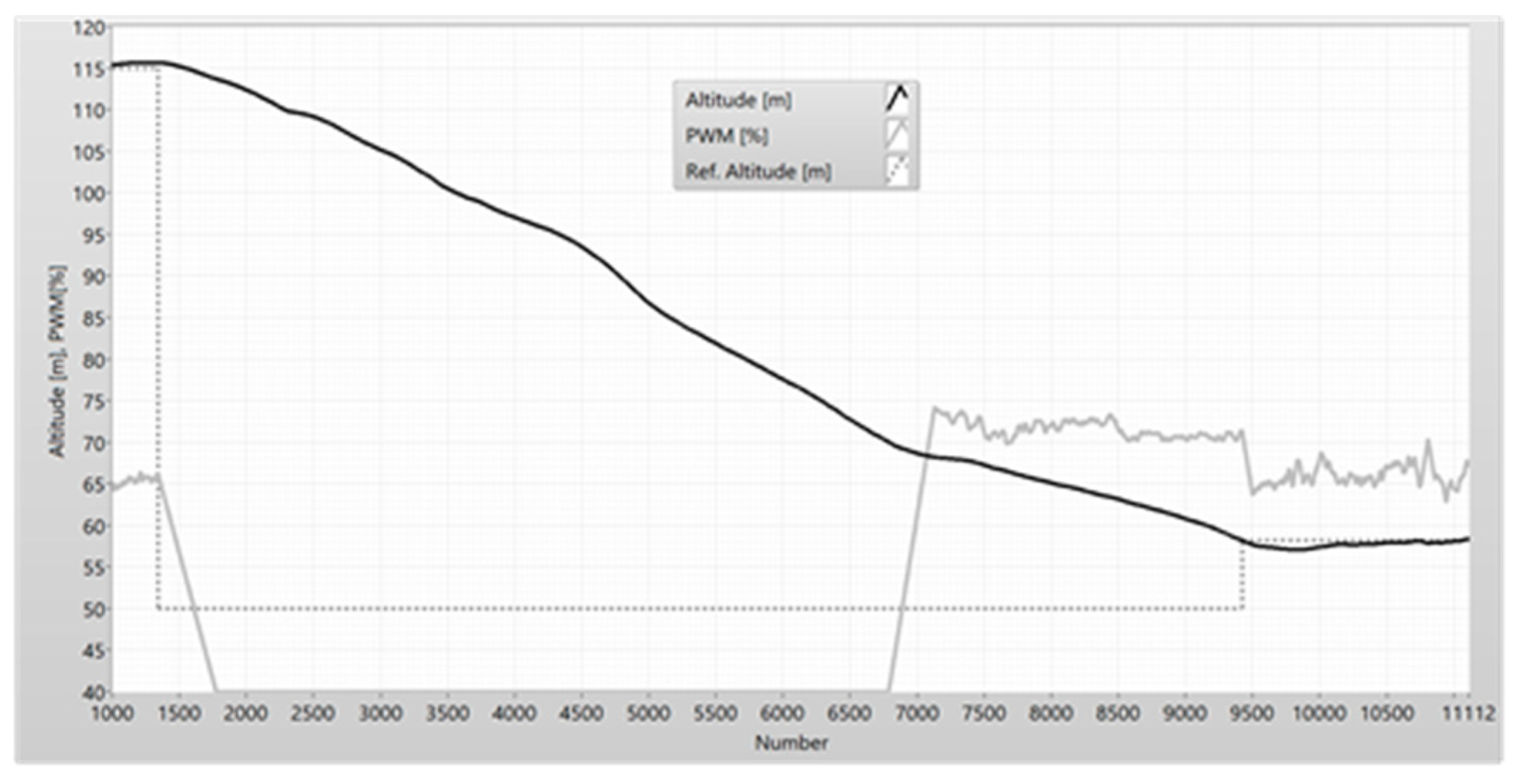
Figure 27.
The vertical speed and the pitch of UAV(a) – filtered parameters (b).
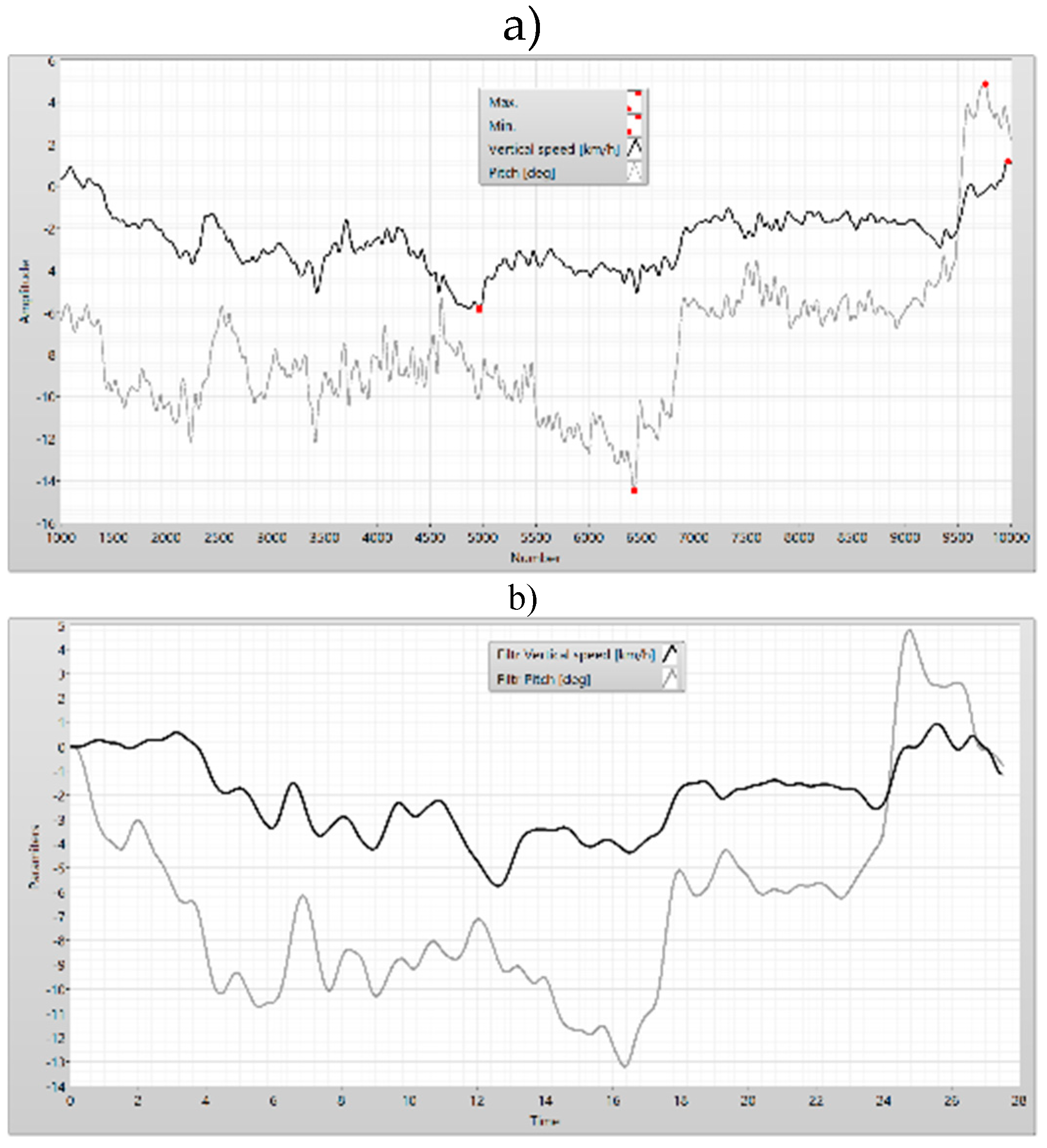
Figure 28.
The airspeed (a) and the filtered airspeed (b) of the UAV.
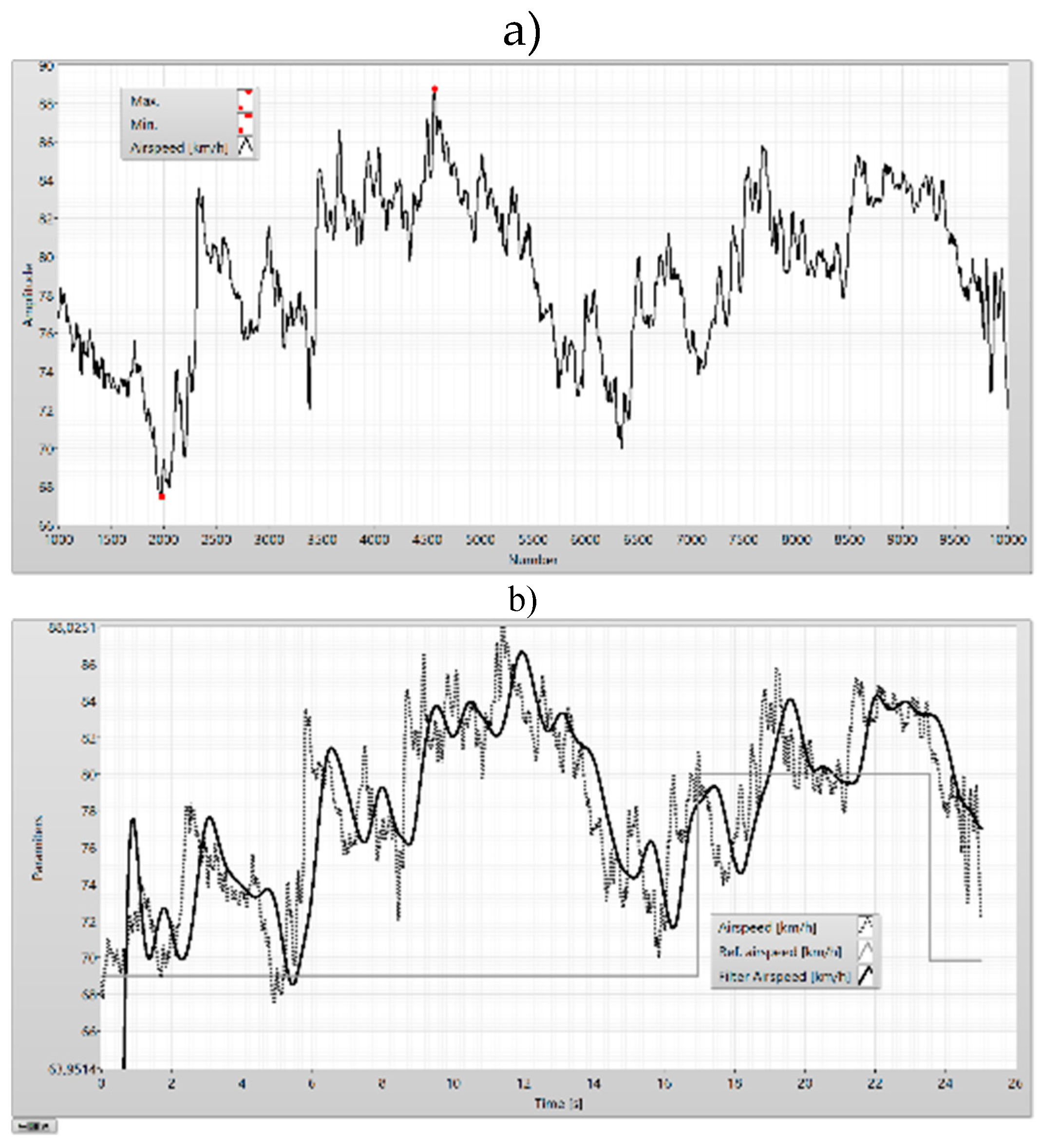
Figure 29.
The airspeed error and the reference pitch in the descending phase.
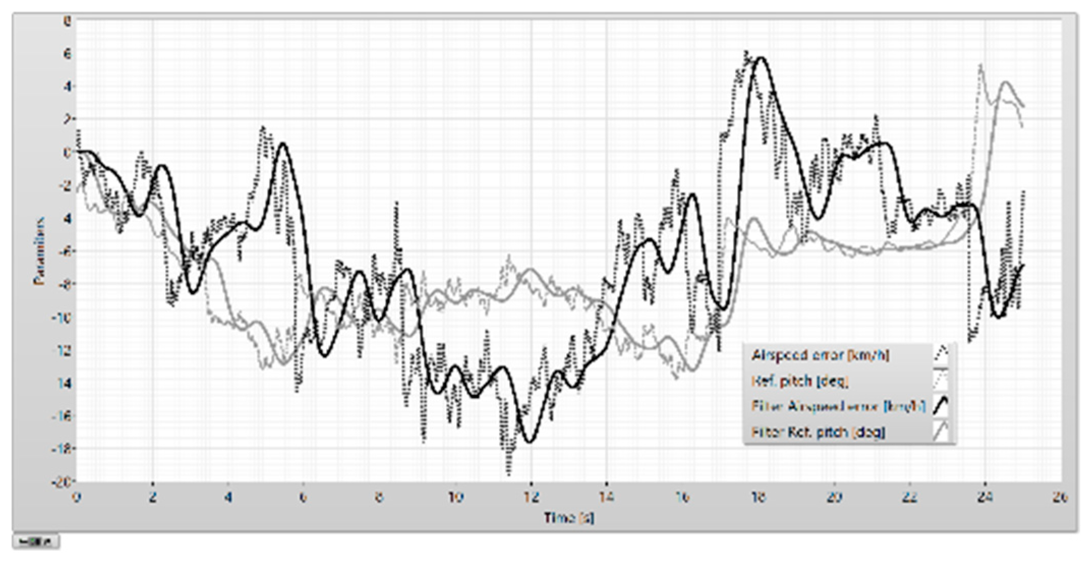
Figure 30.
The altitude error.
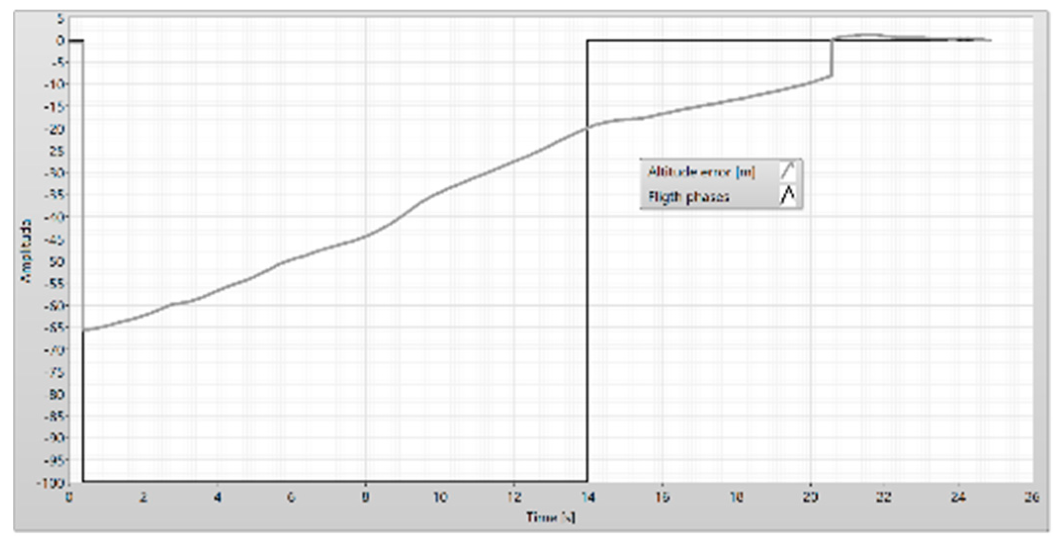
Figure 31.
The altitude and PWM in the climbing state of the UAV.
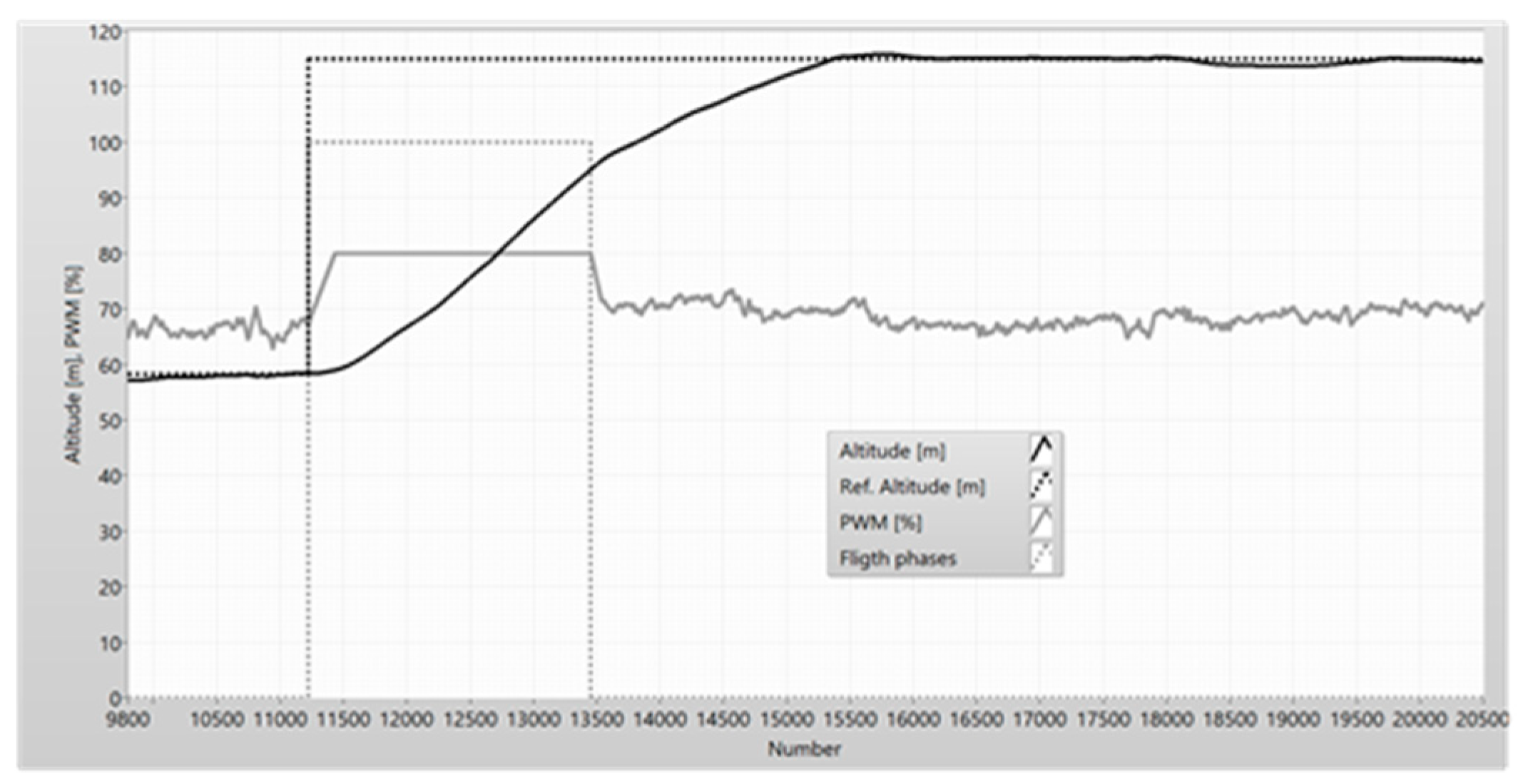
Figure 32.
The pitch, the vertical speed and the altitude error.
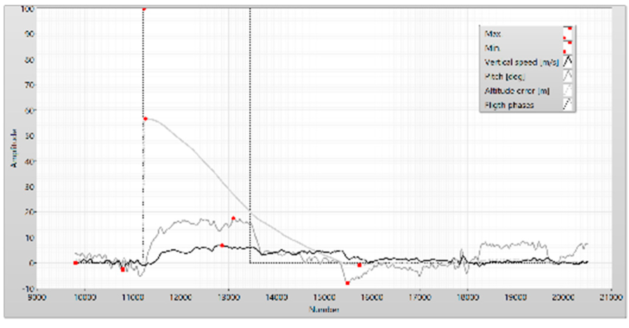
Figure 33.
The pitch error, the airspeed error, and altitude error.
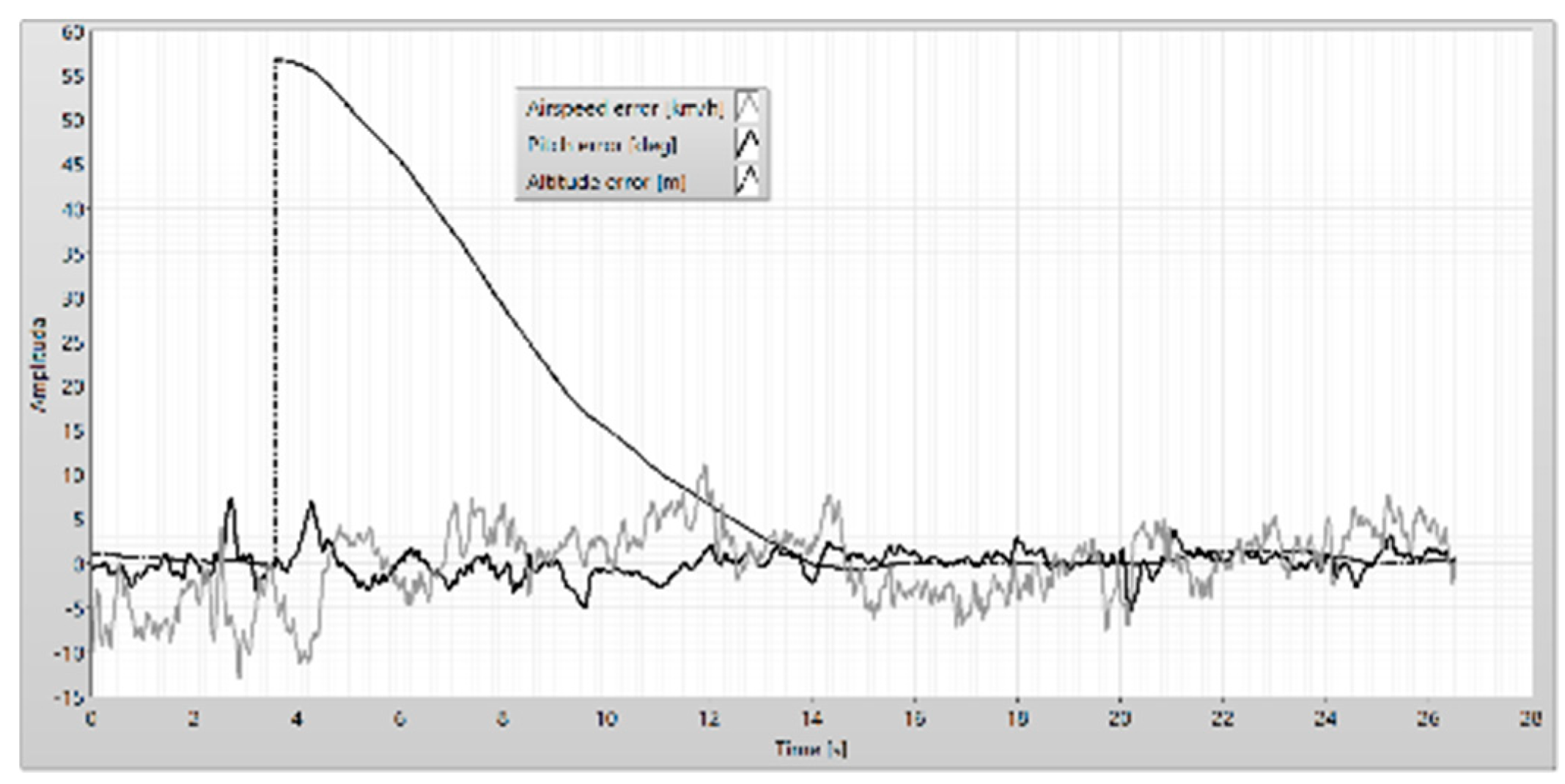
Figure 34.
The airspeed error.
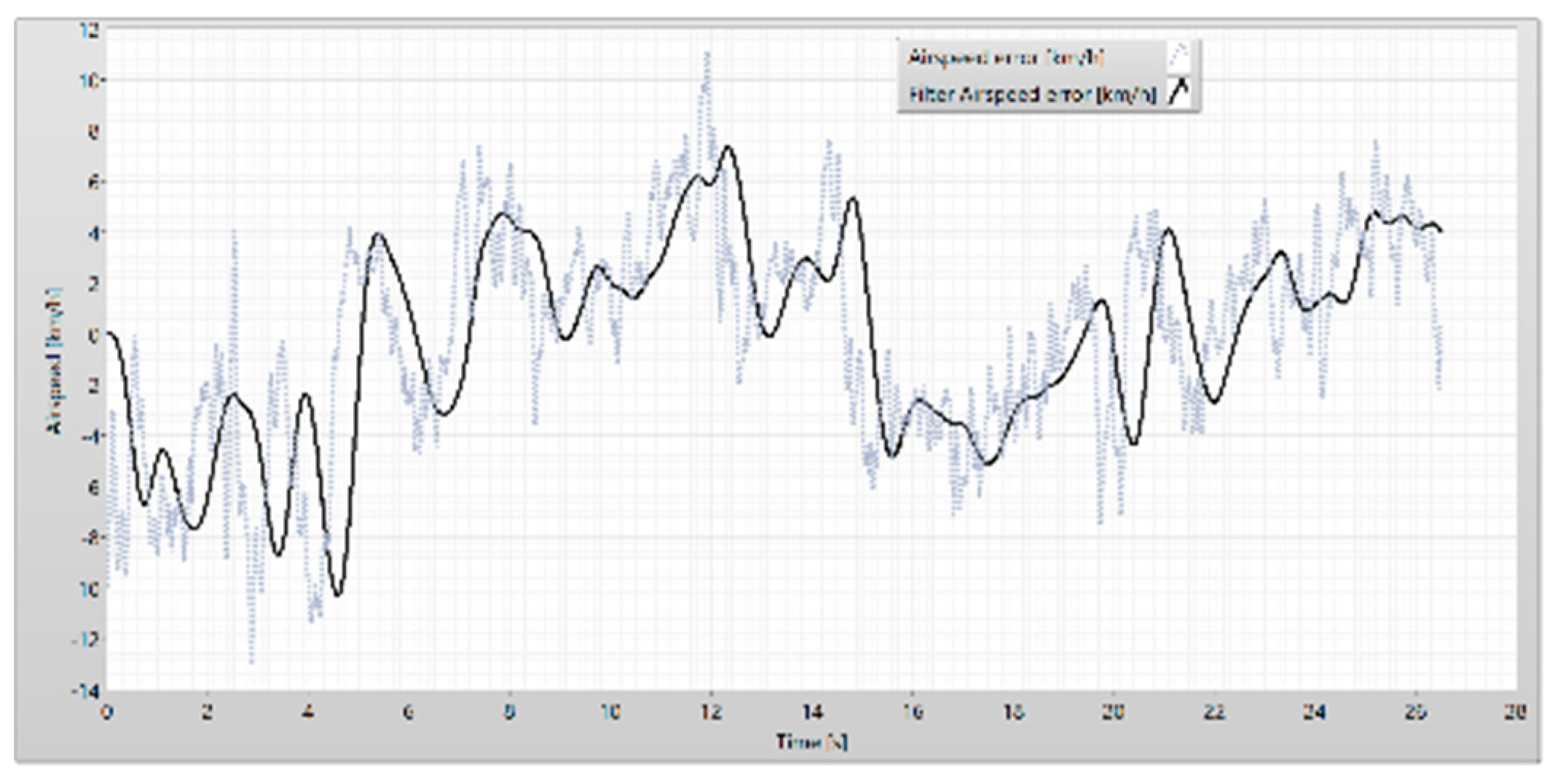
Figure 35.
The pitch error.
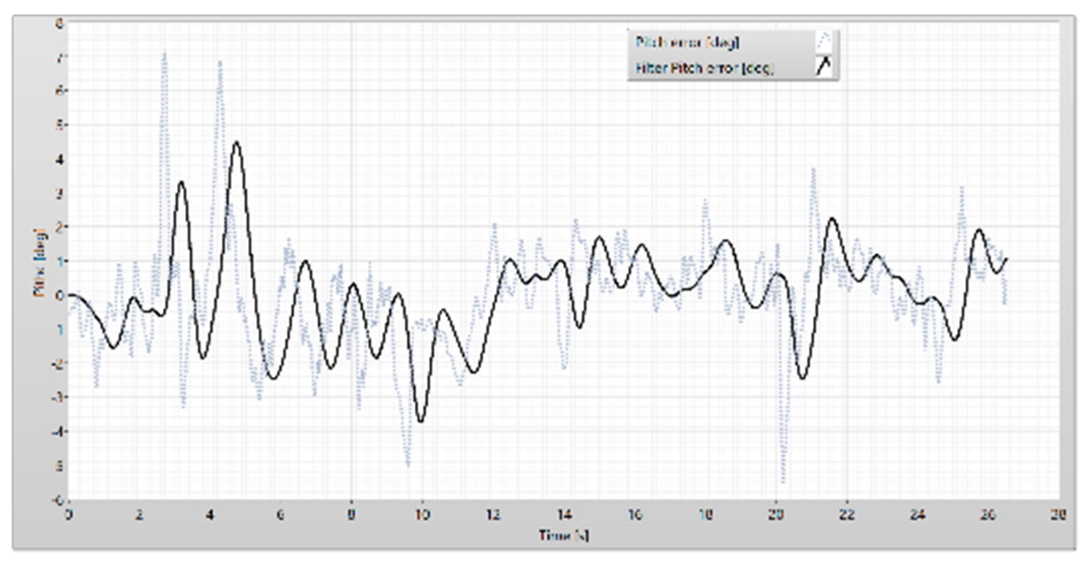
Figure 36.
The phase of the airspeed and the pitch.
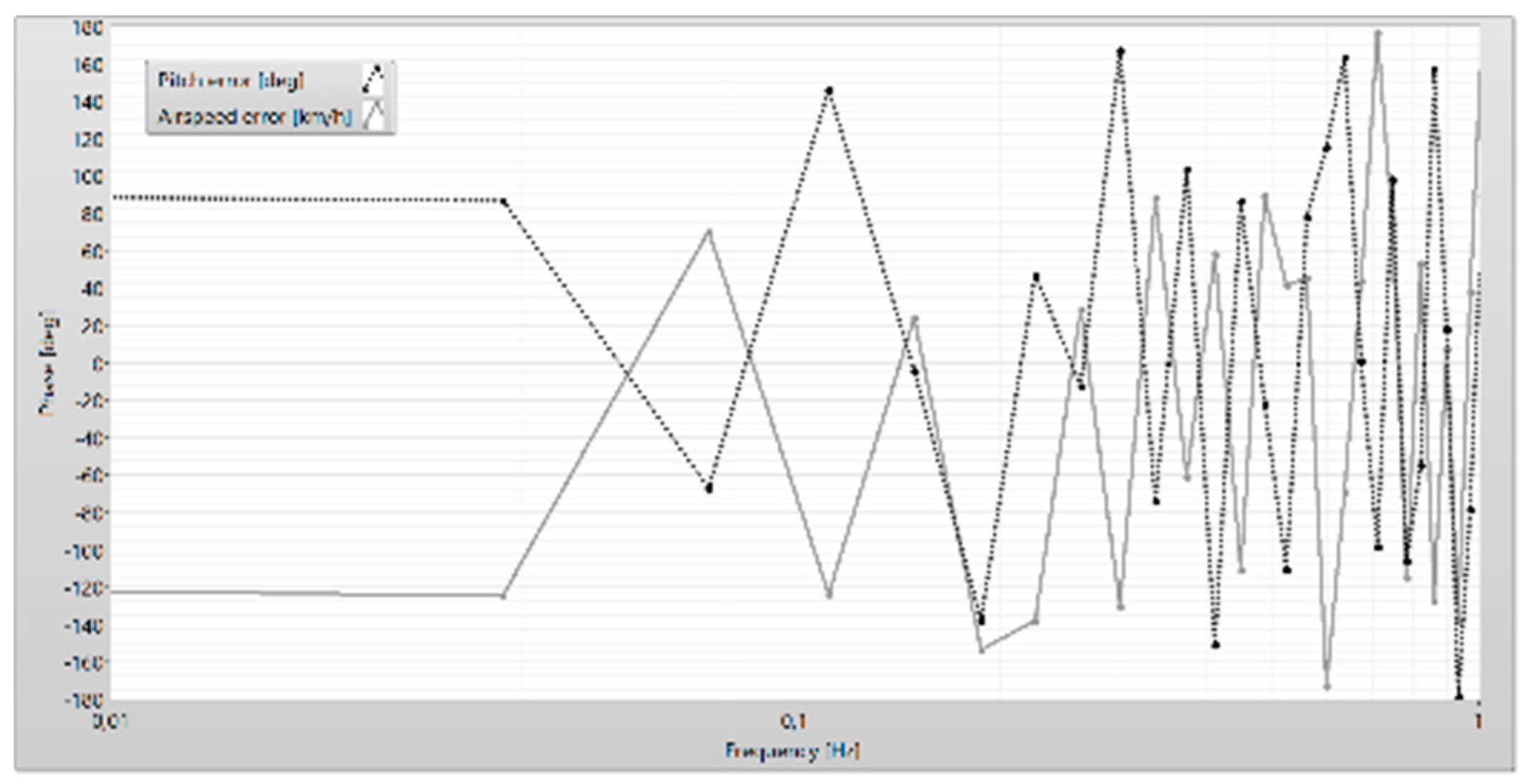
Figure 37.
The model of the wing-in-ground craft.
Disclaimer/Publisher’s Note: The statements, opinions and data contained in all publications are solely those of the individual author(s) and contributor(s) and not of MDPI and/or the editor(s). MDPI and/or the editor(s) disclaim responsibility for any injury to people or property resulting from any ideas, methods, instructions or products referred to in the content. |
© 2024 by the authors. Licensee MDPI, Basel, Switzerland. This article is an open access article distributed under the terms and conditions of the Creative Commons Attribution (CC BY) license (http://creativecommons.org/licenses/by/4.0/).
Copyright: This open access article is published under a Creative Commons CC BY 4.0 license, which permit the free download, distribution, and reuse, provided that the author and preprint are cited in any reuse.


