Submitted:
03 September 2024
Posted:
04 September 2024
You are already at the latest version
Abstract
Spin Assisted Layer-by-Layer (SA-LbL) assembly is one of the Layer-by-Layer (LbL) assembly variants. It is considered as the fastest LbL assembly, however, the deficiency of layering quality on bigger polymeric support size poses a significant challenge to the application of SA-LbL assembly at a larger or industrial scale. To address the challenge, combined spin-spray assisted Layer-by-Layer (SSA-LbL) is employed to prepare membrane. In this study, nanofiltration (NF) thin film composite membranes were prepared by alternate deposition of branched-polyethyleneimine (PEI) and poly(sodium 4-styrenesulfonate) (PSS) on polyethersulfone (PES) ultrafiltration (UF) membrane support. The resulting membrane was then tested to separate NaCl from water. One of the membranes produced in this work, i.e., (PEI/PSS)10 achieved rejection rate of 76.2 %; permeability of 2.79 l/h·m2·bar tested at pressure of 10 bar, temperature of 24.58 ± 0.51 °C , and NaCl-Feed concentration of 2076.75 ± 40.51 ppm. The membrane fouling resistance was also examined in 5 days-test. The membrane showed stable performance and lost only about 30% flux from the initial flux due to fouling which was comparable to that of commercial NF membrane such as NF90. Hence, this work shows that SSA-LbL can be considered as a promising and innovative membrane fabrication technique as it offers flexibility and applicability for preparing membrane from various materials as well as pertinence to industrial scale.
Keywords:
spin-spray coating
; layer-by-layer
; nanofiltration
; reverse osmosis
; fouling resistance
; polyelectrolyte
; multilayer
; thin film composite
1. Introduction
In the last few decades, it is evident the mismatch between water supply and demand has become worse. This condition causes water scarce in many parts of the world. It is generally accepted that the expansion of world population, tremendous development in agriculture and the change of living standard are the main driving forces for the mismatch. The statistics underlined the critical issue of water scarcity affecting a significant portion of the global population. According to reports, approximately two-thirds of the world's population, which translates to around 4 billion people, experience severe water scarcity for at least one month each year. Additionally, about half a billion people face extreme water scarcity throughout the entire year. Experts in the fields keep on innovating and/or improving the water treatment technology aside from many other aspects of water management including the identification of new water resources, improvement of the efficiency of water resources and use, planning national water needs, etc. those efforts are all devoted to ensuring the sustainability of human development that can be greatly affected by water scarcity [1].
Developed around 1970s, Nanofiltration (NF) has long been considered as one of major membrane-based water treatment technologies. It is used in various fields of water treatment including that for surface water [2], groundwater, brackish water [3], and wastewater reuse [4]. It can also be used to remove various water contaminants such as hardness [5], pathogen [6], and natural organic matter [7], and micropollutants [8]. It is characterized by such a small pore size, ca. 150 to 800 Da or 1 to 2 nanometres, that makes it suitable for removal of multivalent ions and other molecules with similar size to them. It exhibits much faster water flux compared to reverse osmosis (RO) membrane. Some reported NF performance can be seen in Table 1. These membranes are typically made of polyamide (PA). As shown, typical NaCl rejection is around 20% to 80% with relatively high flux, more than 20 GFD (34.0 l/m2.h) at a pressure of 110 psi (7.58 bar).
Until now, the polymeric NF membrane that has been dominating the NF membrane market is made of polyamide (PA) with a very small share of cellulose acetate. Nevertheless, commercial NF membrane still has major problems with respect to fouling, a common problem that is also found in almost all pressure driven membrane such as RO, forward osmosis (FO), ultrafiltration (UF) and microfiltration (MF). This problem persists due to both materials i.e. polyamide and its fabrication technique. The two result in highly hydrophobicity and rough surface which are believed as the main reason for membrane fouling [10].
Our work is presented here as an effort to find new materials for membrane prepared using a technique which produces membrane with less tendency to biofouling. Among thin film technologies, LbL has widely been considered as the most versatile and robust technique. It is a bottom-up thin film deposition technique that offers fine control over the film composition, thickness, and many other film properties including hydrophilicity, surface charges, etc [11].
There are various layer by layer assemblies developed since its first development in 1997. LbL assembly is normally conducted through dip/immersion technique in which a substrate is alternately immersed in a polycation and polyanion [12]. The method was then modified by employing spin and spray coating technique instead of immersion. Spin assisted Layer by Layer (SA-LbL) assembly is a time efficient and cost-effective process compared to dip one [13,14]. Meanwhile spray assembly shows better surface coverage and can be employed on much larger substrate size aside from the time efficient compared to dip one [15,16]. Spin and spray technique can then be combined to gain advantages offered by individual technique. Although, there were just few works reported using SSA-LbL such as in the application of thin film for energy storage [17], biofouling mitigation coating on commercial PA thin film composite reverse osmosis (TFC-RO) membrane[18], and fabrication of self-healing thick polymeric film [19].
The observations from our previous works [20] indicate that the SA-LbL (Spin-Assisted Layer-by-Layer) technique resulted in a non-uniform coating layer and insufficient surface coverage. This outcome is attributed to the polymer solution being injected at the center of the support and subsequently spreading towards the edges due to centrifugal force. The thickness of the layer gradually decreases radially [21]. Several factors could contribute to this insufficiency, including the surface roughness of the support layer, the interaction between the polyelectrolyte and the support layer, the viscosity of the polyelectrolyte solution, and the spin speed. For preparation of small membrane sample, the non-uniformity may not have significant effect on the membrane performance as shown in our previous work. However, the extent of non-uniformity and insufficiency in the coating layer becomes more pronounced with larger support size, thereby posing a significant challenge to the application of SA-LbL assembly at a larger or industrial scale.
To address the challenge, alternative methods such as Dip LbL assembly or Spray-Assisted LbL have been considered. However, these methods show slower polyelectrolyte adsorption process compared to SA-LbL which is discouraging the implementation of the technique to produce larger membrane size. Hence, in this work, we have employed a novel approach by coating polyethersulfone (PES) ultrafiltration membranes with polyelectrolytes using SSA-LbL (Spin-Spray-Assisted Layer-by-Layer) assembly. The objective is to harness the advantages of both spin and spray techniques to achieve a uniform coating on a larger membrane support and particularly for rough polymeric supports like the one used in this study. Furthermore, we evaluated the performance of the SSA-LbL coated membranes in short-term tests and longer tests under fouling conditions. This study aims to provide insights into the efficacy of SSA-LbL assembly in producing uniform coatings and its potential applicability in industrial-scale operations.
2. Materials and Methods
2.1. Materials
Weak polycation, i.e., branched-polyethyleneimine (PEI) with molecular weight of 25,000, determined by light scattering, and strong polyanion, i.e., poly(sodium 4-styrenesulfonate) (PSS) with a molecular weight of 70,000 were purchased from Sigma-Aldrich (USA). Both are available from Sigma-Aldrich in 30%wt in H2O. PES ultrafiltration (UF) membranes (YMPWSP3001, Sterlitech Corp., USA) with a pore size corresponding to a molecular weight cut-off of 10 kDa were used as the support layer. All the polyelectrolytes were used without further purification. The molecular structure of the main materials can be seen in Figure 1. All solutions were prepared using ASTM type 1 water (18.2 MΩ, 0.055 μS/cm).
2.2. Polyelectrolyte Membrane (PEM) Thin Film Composite (TFC) Fabrication
Prior to polyelectrolyte deposition, PES support was firstly cleaned in a plasma cleaner (PDC-32-G-2, Harrick Plasma Inc) following a procedure described elsewhere [22]. This treatment is important not only to clean the support surface before deposition but also to introduce oxygen-containing polar groups, thereby rendering the surface more hydrophilic and more highly negatively charged.
PEI and PSS solutions were prepared from the raw material (30%wt in H2O as mentioned in section 2.1). The desired concentration was desired at 0.02 M based on molecular weight of repeating unit. NaCl was added to them afterward to make the polyelectrolyte solution contain 0.05 M NaCl. Finally, the pH of both PEI and PSS solution was adjusted to pH 8 [23].
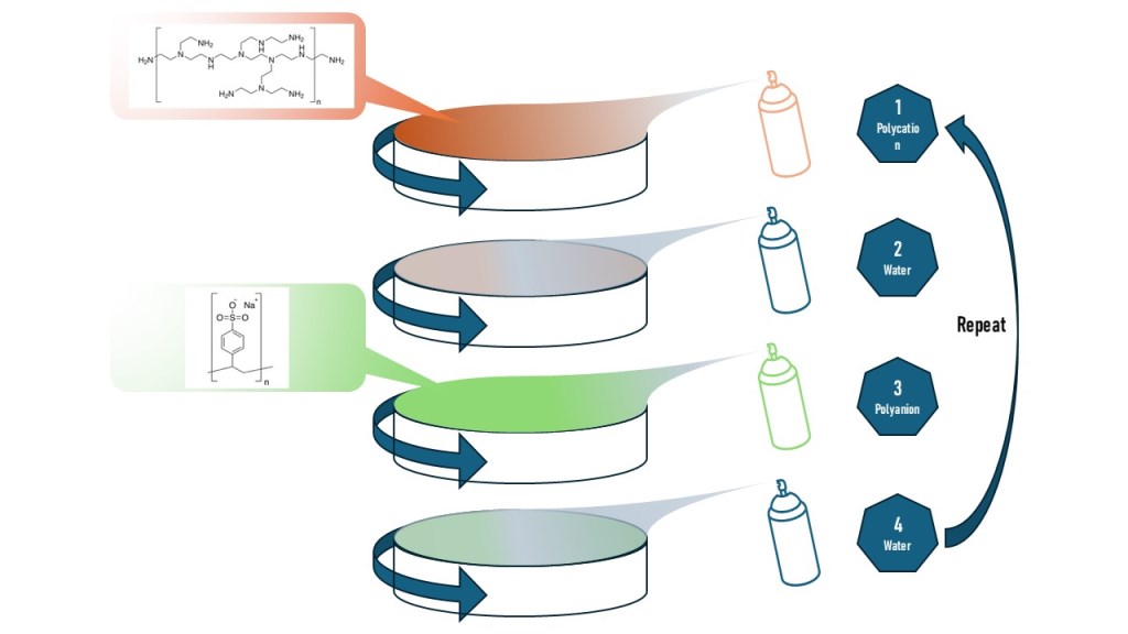
The alternate deposition of PEI and PSS on PES support was done as follows, firstly, the PEI solution was sprayed on a spinning PES support at a rate of 0.2 mL/s for 10 s, and the resulting film was subsequently spin-dried for the next 10 s. The support was spun at a speed of 3000 rpm [24] and the polyelectrolyte solution was sprayed when the spin speed reached the desired rpm. The dry film was then rinsed with deionized (DI) water at a rate of 0.8 mL/s for 10 s to remove any weakly bonded polyelectrolyte molecules. This was then followed by another spin-drying for 10 s. The PSS solution was sprayed exactly in the same way as PEI solution was. After this deposition, the cycle is completed and can be repeated as many as required. After completion of deposition, the PEM membrane was rinsed and stored in distilled water until the permeation test.
2.3. Characterization
2.3.1. Film Thickness
The thickness of thin layer prepared by SSA-LbL assembly was measured using KLA Tencor AlphaStep® D-500 stylus profilometer. Stylus speed of 0.01 mm/s with stylus force of 0.2 mg was employed during the measurement. The thickness measurement was taken at 3 different locations on each sample.
2.3.2. Hydrophilicity
Membrane hydrophilicity was measured using Biolin Theta Flex® optical tensiometer. A 10 μL water droplet at 20°C was dispensed on the membrane surface. A live-contact angle analysis was operated since the water droplet dispensed slowly until it was droppen on the membrane surface. The high-resolution camera recorded the contact angle for 10 seconds. The installed Biolin Scientific software will analyze the recorded images and calculate the average contact angle.
2.3.3. Surface Charge
Surface charge is one of the important surface properties particularly in the case of NF membrane. Because Donnan exclusion is affected by the surface charge of the membrane. For this purpose, Anton Parr Surpass 3(R) surface zeta potential analyser was utilized. The surface charge was measured with interfacial double layer thickness of 100 μm utilizing 0.01 M KCl solution at temperature of 24.37 ± 0.47 °C and pH of 5.72 ± 0.08.
2.3.4. Surface Topography and Surface Roughness
The surface topography and surface roughness of the SSA-LbL films formed on PES UF membranes were characterized and analyzed using an atomic force microscopy (AFM) system, specifically the TOSCA® from Anton Paar. The AFM system operated in contact mode to investigate the surface topography. Silicon scanning probes with spring constants of 0.2 N/m (AP-Arrow-CONTR-10 model) were utilized during the characterization process. The reported values in this study are averages derived from measurements taken at three random locations on the specimen.
3. Results and Discussion
3.1. Surface Characteristics
We have successfully fabricated spin-spray LbL polyelectrolyte membrane. The evidence of successful deposition can be seen from alteration of several surface properties such as hydrophilicity shown by contact angle data; surface charge; film thickness and surface roughness. The surface properties are presented in Table 2 down below.
The pristine plasma cleaned PES UF i.e, number of bilayers 0 shows rather highly negative charge because of the presence of oxygen containing polar groups on the surface. Adding number of bilayers causes the alteration of all measured surface properties which is evidence of successful deposition. As shown the surface charges alters from negatively charge to slightly positively charge at number of bilayers of 3. PSS is strong polyelectrolyte which is fully ionized regardless the pH of the solution. On the other hand, PEI is classified as a weak polyelectrolyte that means the degree of ionization depends on the surrounding pH.
It is important to note that all membrane samples in this work were capped with PSS as the outermost layer. The net charge of the membrane is positive although PSS is negatively charged polymer. It can be explained that both PEI and PSS were prepared at pH 8 which causes PEI to be less ionized, meaning more ionizable groups remain unprotonated. During surface charge characterization, these unprotonated groups become protonated due to lower pH of the 0.01 M KCl solution i.e. around 5.8. Since these positively charged groups are not compensated by their polyanion counterpart, it leads to a net positively charged surface. The addition of more PEI layers results in an increased number of these unprotonated ionizable groups, which, indeed upon the protonation, contribute to a higher positive charge on the surface.
Like surface charge, the hydrophilicity of SS-LbL PEI/PSS alters from slightly hydrophobic for the pristine PES UF support before deposition and becomes more and more hydrophilic as the number of deposited bilayers increases. This is also evidence of successful deposition. Both PEI and PSS are characterized as hydrophilic material because of the presence of amine group in PEI and sulfonate group in PSS. The two functional groups interact with water molecules very well with PSS is even more hydrophilic than PEI. Overall, the additional PEI/PSS changes the surface properties of PES UF support to be more hydrophilic because the effect of hydrophobicity from PES support becomes less pronounced with the increasing number of bilayers.
The surface topography of SS LbL PEI/PSS NF membranes was carefully examined, as illustrated in Figure 2. The pristine PES UF membrane exhibits a notable roughness with an RMS roughness value of 15.735 ± 5.11 nm, as detailed in Table 2. However, the topography undergoes significant change upon the deposition of PEI/PSS layers. As the number of deposited layers increases, a marked smoothing of the surface is observed, evidenced by a reduction in RMS roughness from 15 to 7 nm and to 4 nm, for 5 and 10 bilayers, respectively. This trend indicates that the addition of PEI/PSS layers effectively smoothens the membrane surface, enhancing its structural properties.
3.2. Permeation Test Result and Comparison with Other LbL Membranes
The test for this membrane was done for nanofiltration applications. The result of permeability and rejection rate as a function of number of bilayers is shown in Figure 2. As shown, the rejection rate increases with an increasing number of bilayers, while permeability inversely correlates with the rejection rate.
This result could be explained as follows. The addition of bilayer results in increased thickness as it is evidence in Table 2. It is generally accepted that membrane permeability is inversely proportional with the thickness due to the path for the water and salt molecules to pass through the membrane becomes longer. This result is clearly depicted Figure 2.
In addition, it is apparent that there is increasing charge as growing number of bilayers as shown in Table 2. The increased charge enhances membrane ability to repel the ions of similar charge which is known as Donnan’s exclusion mechanism. It results in an increase in NaCl rejection rate.
Figure 3.
Spin-spray assisted layer-by-layer polyelectrolyte multilayer nanofiltration membrane performance (Experimental condition: pressure of 10 bar, cross flow velocity (CFV) of 0.65 m/s, NaCl-Feed concentration of 2076.75 ± 40.51 ppm, the pH of the feed solution of 6.27 ± 0.15).
Figure 3.
Spin-spray assisted layer-by-layer polyelectrolyte multilayer nanofiltration membrane performance (Experimental condition: pressure of 10 bar, cross flow velocity (CFV) of 0.65 m/s, NaCl-Feed concentration of 2076.75 ± 40.51 ppm, the pH of the feed solution of 6.27 ± 0.15).
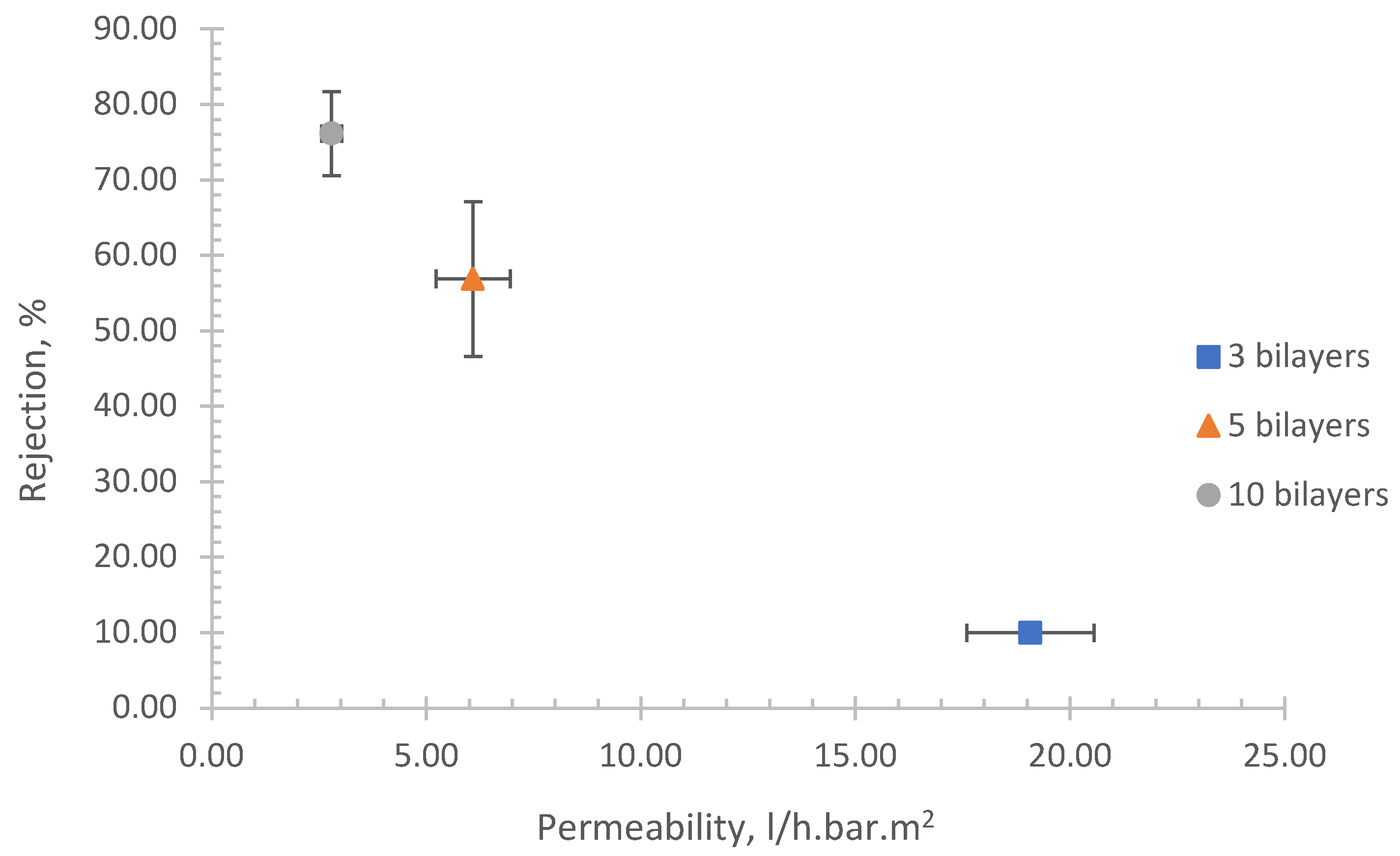
It is evident from Table 3 that our SSA-LbL membrane demonstrates superior performance in terms of permeability achieved at lower pressures when compared to other LbL NF membranes fabricated using various methods such as dip LbL, spray, and spin-assisted and various material such as Sodium Alginate (SA), Chitosan (Chi), polyallylamine hydrochloride (PAH). It is also noteworthy that our SSA (PEI/PSS)10; (PEI/PSS)5 ; and (PEI/PSS)3 membranes exhibiting flux of 27.9 at 10 bar; 60.9 and 190.7 l/m2.h, respectively, are competitive with those of commercial NF membranes as outlined in Table 1.
These results highlight the potential of our method for the efficient fabrication of NF membranes, offering enhanced performance and broader applications. This advancement could lead to significant improvements in various industrial processes that rely on high-performance NF membranes.
3.3. Fouling Test
As previously mentioned, biofouling is most problematic with typical polyamide NF/RO membrane due to its highly hydrophobicity, relatively high roughness. Thus, we also studied fouling resistance SSA LbL PEI/PSS membrane utilizing feed water containing bovine serum albumin (BSA). It is widely used as a foulant representative in membrane studies to simulate biofouling conditions. This practice is due to BSA’s well-characterized properties and its relevance as a model protein for understanding the fouling behaviour of biological macromolecules.
The data presented in Figure 4 illustrates the decline in normalized permeability over the course of the test, which was conducted at a constant pressure of 10 bar for a duration of two days. Prior to this test, the membrane was compacted at higher pressure, i.e. 15 bar for 2 days and then followed by one day membrane equilibrating at 10 bar. In the end of equilibrating phase, the flux was measured and taken as initial flux which was 43.0 l/m2.h. Afterward, BSA was introduced, and the flux was measured continuously. The flux presented in Figure 4 is a normalized flux which is determined by dividing the real-time flux by the initial flux.
As mentioned, the membrane was pre-compacted prior to the fouling test to ensure that any slight pressure increases above the desired operating pressure of 10 bar during the test would not result in further membrane compaction. Therefore, any observed decrease in permeability can be attributed solely to the formation of a fouling layer on the membrane surface. As shown, the gradual decline in water flux through the membrane occurs during the first 1500 min of fouling experiment. The flux decline was around 30% from original flux, this decline is because the fouling layer thickens and provides more and more barriers for water to pass through. Apparently, the effect of membrane surface is almost diminished after 1500 min and further fouling happened due to solely interaction between existing fouling layer with BSA. This interaction is not strong compared to that between BSA molecules and membrane surface. We also tested commercial filmtecTM NF90 membrane from Dupont. The outcome showed that both membranes have comparable performance with respect to fouling resistance.
4. Conclusions
Spin-spray Layer-by-layer assembly was successfully utilized to prepare thin film composite NF membrane consist of PES support with thin layers of PEI/PSS. This work aimed to study the applicability of the combined methods i.e. spin and spray assembly to produce defect free larger polyelectrolyte multilayer membrane. This objective should be investigated soon.
In general, the resulting membrane from this work shows performance comparable or even superior to that of the commercial membranes. For instance, (PEI/PSS)5 shows rejection rate of 57% with flux of 61 l/m2.h which is comparable to TS40 (rejection rate of 50% and flux of 34 l/m2.h). similarly, (PEI/PSS)3 showing rejection rate of 10% with very high flux of 190.7 l/m2.h are comparable to XN45, NFG, and NFW. Not only does the membrane exhibits comparable performance in terms of rejection and flux but also in terms of fouling resistance as shown in Figure 4. Thus, this method could be a promising and innovative approach to fabricate NF membrane as the technique itself offers a high level of flexibility and freedom in precisely controlling the surface properties and composition or material of the film.
Author Contributions
For research articles with several authors, a short paragraph specifying their individual contributions must be provided. The following statements should be used “Conceptualization, Farid. and Saad.; methodology, Farid and Saad.; software, Farid and karim; validation, Farid and Karim.; formal analysis, Farid and Karim.; investigation, Karim; resources, Farid and Saad.; data curation, Farid and Saad; writing—original draft preparation, Farid.; writing—review and editing, Saad; visualization, Fekri.; supervision, Farid.; project administration, Farid.; funding acquisition, Farid. All authors have read and agreed to the published version of the manuscript.”
Funding
This research was funded by King Abdulaziz City for Science and Technology (KACST) - National Science, Technology and Innovation Plan (NSTIP) under project number: 14-WAT68-08-R.
Conflicts of Interest
Declare conflicts of interest or state “The authors declare no conflicts of interest.” Authors must identify and declare any personal circumstances or interest that may be perceived as inappropriately influencing the representation or interpretation of reported research results. Any role of the funders in the design of the study; in the collection, analyses or interpretation of data; in the writing of the manuscript; or in the decision to publish the results must be declared in this section. If there is no role, please state “The funders had no role in the design of the study; in the collection, analyses, or interpretation of data; in the writing of the manuscript; or in the decision to publish the results”.
References
- M.M. Mekonnen, A.Y. Hoekstra, Four billion people facing severe water scarcity, Sci Adv 2 (2024) e1500323. https://doi.org/10.1126/sciadv.1500323. [CrossRef]
- J. Lee, M. Zhan, Y. Kim, S. Hong, Comparison of different cleaning strategies on fouling mitigation in hollow fiber nanofiltration membranes for river water treatment, J Clean Prod 380 (2022) 134764. https://doi.org/https://doi.org/10.1016/j.jclepro.2022.134764. [CrossRef]
- Srivastava, R. Singh, V.D. Rajput, T. Minkina, S. Agarwal, M.C. Garg, A systematic approach towards optimization of brackish groundwater treatment using nanofiltration (NF) and reverse osmosis (RO) hybrid membrane filtration system, Chemosphere 303 (2022) 135230. https://doi.org/https://doi.org/10.1016/j.chemosphere.2022.135230. [CrossRef]
- M. Giagnorio, F. Ricceri, M. Tagliabue, L. Zaninetta, A. Tiraferri, Hybrid Forward Osmosis–Nanofiltration for Wastewater Reuse: System Design, Membranes (Basel) 9 (2019). https://doi.org/10.3390/membranes9050061. [CrossRef]
- F. Elazhar, M. Elazhar, S. El-Ghzizel, M. Tahaikt, M. Zait, D. Dhiba, A. Elmidaoui, M. Taky, Nanofiltration-reverse osmosis hybrid process for hardness removal in brackish water with higher recovery rate and minimization of brine discharges, Process Safety and Environmental Protection 153 (2021) 376–383. https://doi.org/https://doi.org/10.1016/j.psep.2021.06.025. [CrossRef]
- R. Singh, R. Bhadouria, P. Singh, A. Kumar, S. Pandey, V.K. Singh, Chapter 21 - Nanofiltration technology for removal of pathogens present in drinking water, in: M.N. Vara Prasad, A. Grobelak (Eds.), Waterborne Pathogens, Butterworth-Heinemann, 2020: Pp. 463–489. https://doi.org/https://doi.org/10.1016/B978-0-12-818783-8.00021-9. [CrossRef]
- S. Wang, L. Li, S. Yu, B. Dong, N. Gao, X. Wang, A review of advances in EDCs and PhACs removal by nanofiltration: Mechanisms, impact factors and the influence of organic matter, Chemical Engineering Journal 406 (2021) 126722. https://doi.org/https://doi.org/10.1016/j.cej.2020.126722. [CrossRef]
- J. Cuhorka, E. Wallace, P. Mikulášek, Removal of micropollutants from water by commercially available nanofiltration membranes, Science of The Total Environment 720 (2020) 137474. https://doi.org/https://doi.org/10.1016/j.scitotenv.2020.137474. [CrossRef]
- Sterlitech, Flat sheet Membrane, (n.d.). https://www.sterlitech.com/flat-sheet-membranes.html (accessed March 19, 2024).
- N.N.R. Ahmad, A.W. Mohammad, E. Mahmoudi, W.L. Ang, C.P. Leo, Y.H. Teow, An Overview of the Modification Strategies in Developing Antifouling Nanofiltration Membranes, Membranes (Basel) 12 (2022). https://doi.org/10.3390/membranes12121276. [CrossRef]
- X. Zhang, Y. Xu, X. Zhang, H. Wu, J. Shen, R. Chen, Y. Xiong, J. Li, S. Guo, Progress on the layer-by-layer assembly of multilayered polymer composites: Strategy, structural control and applications, Prog Polym Sci 89 (2019) 76–107. https://doi.org/https://doi.org/10.1016/j.progpolymsci.2018.10.002. [CrossRef]
- G. Decher, Fuzzy nanoassemblies: Toward layered polymeric multicomposites, Science (1979) 277 (1997) 1232–1237. https://doi.org/10.1126/science.277.5330.1232. [CrossRef]
- P.A. Chiarelli, M.S. Johal, J.L. Casson, J.B. Roberts, J.M. Robinson, H.L. Wang, Controlled Fabrication of Polyelectrolyte Multilayer Thin Films Using Spin-Assembly, Advanced Materials 13 (2001) 1167–1171. https://doi.org/10.1002/1521-4095(200108)13:15<1167::aid-adma1167>3.0.co;2-a. [CrossRef]
- S.-S. Lee, J.-D. Hong, C.H. Kim, K. Kim, J.P. Koo, K.-B. Lee, Layer-by-Layer Deposited Multilayer Assemblies of Ionene-Type Polyelectrolytes Based on the Spin-Coating Method, Macromolecules 34 (2001) 5358–5360. https://doi.org/10.1021/ma0022304. [CrossRef]
- J.B. Schlenoff, S.T. Dubas, T. Farhat, Sprayed Polyelectrolyte Multilayers, Langmuir 16 (2000) 9968–9969. https://doi.org/10.1021/la001312i. [CrossRef]
- Izquierdo, S.S. Ono, J.C. Voegel, P. Schaaf, G. Decher, Dipping versus Spraying:  Exploring the Deposition Conditions for Speeding Up Layer-by-Layer Assembly, Langmuir 21 (2005) 7558–7567. https://doi.org/10.1021/la047407s. [CrossRef]
- F.S. Gittleson, D. Hwang, W.-H. Ryu, S.M. Hashmi, J. Hwang, T. Goh, A.D. Taylor, Ultrathin Nanotube/Nanowire Electrodes by Spin–Spray Layer-by-Layer Assembly: A Concept for Transparent Energy Storage, ACS Nano 9 (2015) 10005–10017. https://doi.org/10.1021/acsnano.5b03578. [CrossRef]
- W. Ma, A. Soroush, T. Van Anh Luong, G. Brennan, Md.S. Rahaman, B. Asadishad, N. Tufenkji, Spray- and spin-assisted layer-by-layer assembly of copper nanoparticles on thin-film composite reverse osmosis membrane for biofouling mitigation, Water Res 99 (2016) 188–199. https://doi.org/https://doi.org/10.1016/j.watres.2016.04.042. [CrossRef]
- M.N.H. Kashem, X. Liu, Z. Ding, W. Li, Spin-spray-assisted layer-by-layer assembly of thick polymer films with self-healing, UV-protection, and anti-fog properties, Journal of Polymer Science 61 (2023) 1040–1051. https://doi.org/https://doi.org/10.1002/pol.20220481. [CrossRef]
- F. Fadhillah, CROSSLINKED SPIN-ASSISTED LAYER-BY-LAYER POLYELECTROLYTE NANOFILTRATION MEMBRANE: FROM LITERATURE REVIEW TO EXPERIMENT, Indonesian Journal of Science and Technology 1 (2021) 117–130.
- A. Zhuk, V. Selin, I. Zhuk, B. Belov, J.F. Ankner, S.A. Sukhishvili, Chain conformation and dynamics in spin-assisted weak polyelectrolyte multilayers, Langmuir 31 (2015) 3889–3896.
- K.S. Kim, K.H. Lee, K. Cho, C.E. Park, Surface modification of polysulfone ultrafiltration membrane by oxygen plasma treatment, J Memb Sci 199 (2002) 135–145. https://doi.org/https://doi.org/10.1016/S0376-7388(01)00686-X. [CrossRef]
- A.M. Alghamdi, Fast and Versatile Pathway in Fabrication of Polyelectrolyte Multilayer Nanofiltration Membrane with Tunable Properties, J Chem 2021 (2021) 9978596. https://doi.org/10.1155/2021/9978596. [CrossRef]
- F. Fadhillah, S.M. Javaid Zaidi, Z. Khan, M.M. Khaled, P.T. Hammond, Reverse osmosis desalination membrane formed from weak polyelectrolytes by spin assisted layer by layer technique, Desalination Water Treat 34 (2011) 44–49. https://doi.org/10/5004/dwt.2011.2856. [CrossRef]
- R.H. Lajimi, A. Ben Abdallah, E. Ferjani, M.S. Roudesli, A. Deratani, Change of the performance properties of nanofiltration cellulose acetate membranes by surface adsorption of polyelectrolyte multilayers, Desalination 163 (2004) 193–202.
- W. Ritcharoen, P. Supaphol, P. Pavasant, Development of polyelectrolyte multilayer-coated electrospun cellulose acetate fiber mat as composite membranes, Eur Polym J 44 (2008) 3963–3968.
- K.L. Cho, A.J. Hill, F. Caruso, S.E. Kentish, Chlorine Resistant Glutaraldehyde Crosslinked Polyelectrolyte Multilayer Membranes for Desalination, Advanced Materials 27 (2015) 2791–2796. https://doi.org/https://doi.org/10.1002/adma.201405783. [CrossRef]
Figure 1.
Molecular structures of materials used to synthesize PEM TFC membranes: (a) Branched PEI (b) PSS, and (c) PES.
Figure 1.
Molecular structures of materials used to synthesize PEM TFC membranes: (a) Branched PEI (b) PSS, and (c) PES.
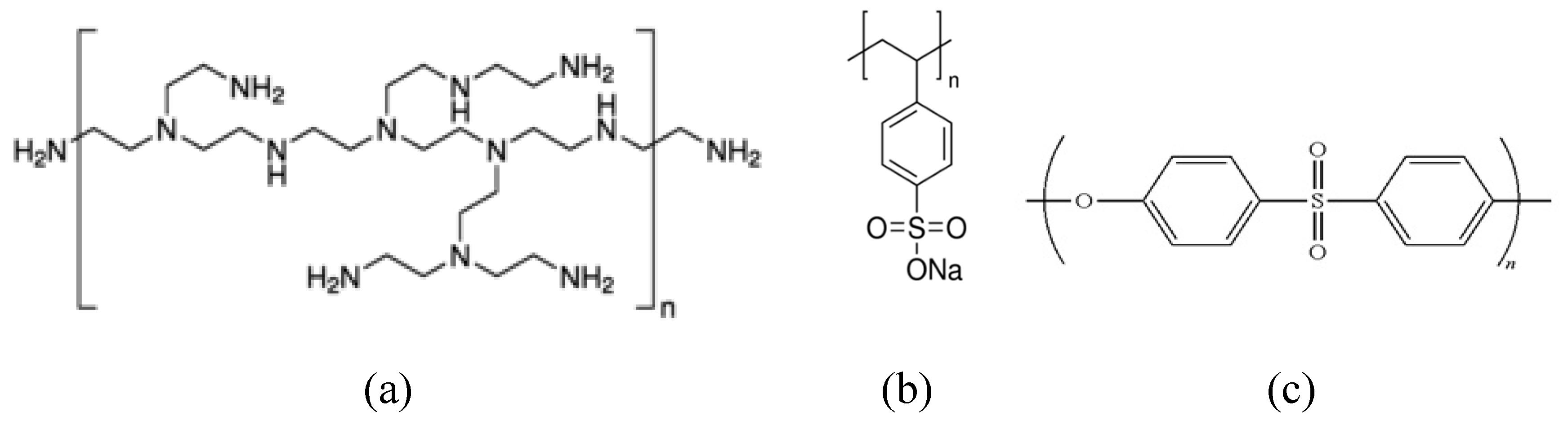
Figure 2.
Atomic Force Microscope for selected samples i.e., (a) Pristine PES UF membrane as support; (b) (PEI/PSS)5; (c) (PEI/PSS)10.
Figure 2.
Atomic Force Microscope for selected samples i.e., (a) Pristine PES UF membrane as support; (b) (PEI/PSS)5; (c) (PEI/PSS)10.
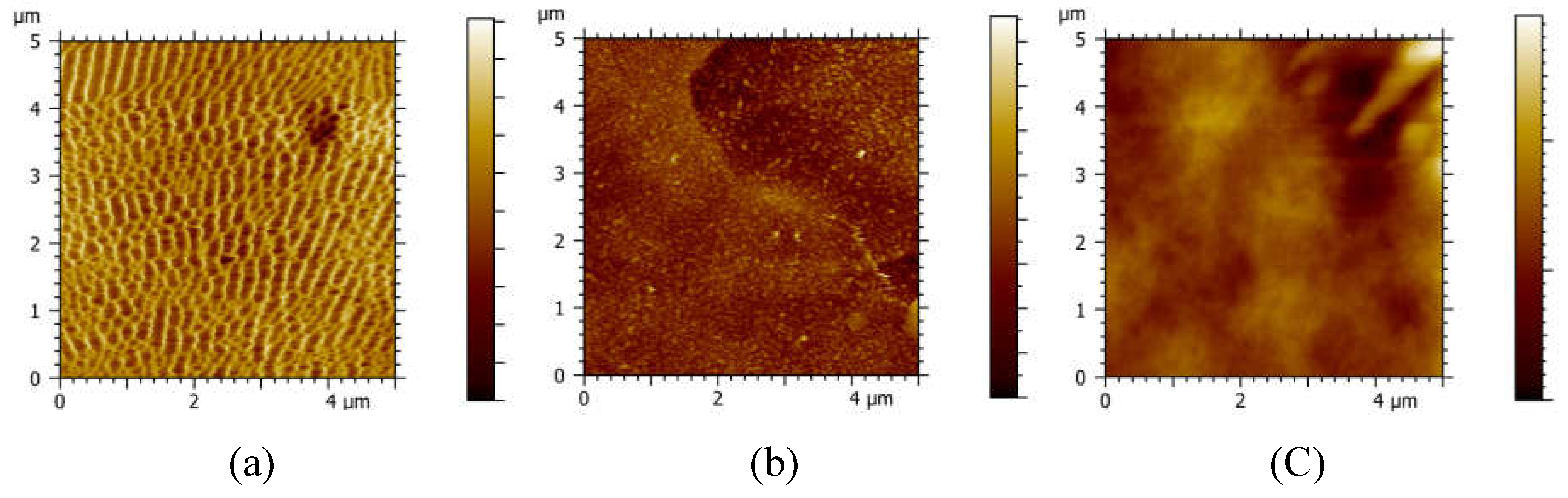
Figure 4.
Membrane rejection rate and normalized permeability for long term permeation test of uncrosslinked-(PEI/PSS)3 using bovine serum albumin as foulant. (put condition here).
Figure 4.
Membrane rejection rate and normalized permeability for long term permeation test of uncrosslinked-(PEI/PSS)3 using bovine serum albumin as foulant. (put condition here).
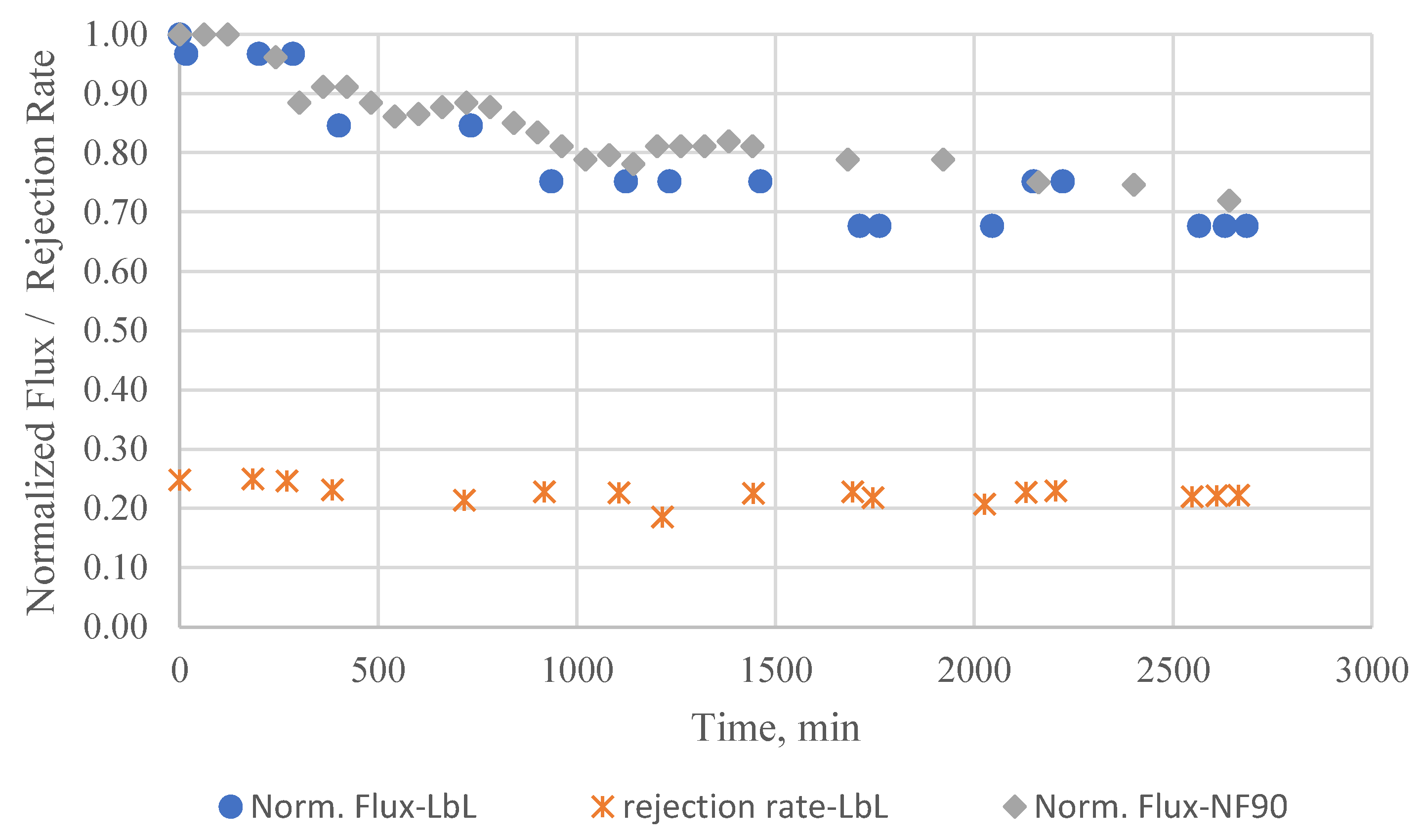

Table 1.
NF membrane performance as reported by Sterlitech Corporation [9].
Table 1.
NF membrane performance as reported by Sterlitech Corporation [9].
| Manufacturer | Type | Polymer | Feed | Flux (l/m2.h)/ at pressure (bar) | NaCl Rejection |
|---|---|---|---|---|---|
| Synder™ | NFX | PA-TFC | Foods/Industrial/Wastewater | 51-59.5 / 7.58 | 40% |
| NFW | PA-TFC | Foods/Industrial/Wastewater | 85-93.5 / 7.58 | 20% | |
| NFG | PA-TFC | Foods/Industrial/Wastewater | 111-119 / 7.58 | 10% | |
| NDX | PA-TFC | Foods/Industrial/Wastewater | 59.5-76.5 / 7.58 | 30% | |
| TriSep™ | TS80 | PA-TFC | Foods/Industrial/Wastewater | 57.8 /7.58 | 80-90% |
| SB90 | CA Blend | Liquid Foods | 51 /15.5 | 85% | |
| TS40 | Polypiperazine-amide-TFC | Foods/Industrial/Wastewater | 34 / 7.58 | 40-60% | |
| XN45 | Polypiperazine-amide-TFC | Foods/Industrial/Wastewater | 59.5 / 7.58 | 10-30% | |
Table 2.
Surface properties of the membrane.
| Number of Bilayer | Surface charge mV |
Contact angle ° |
Thickness nm |
RMS Roughness nm |
|---|---|---|---|---|
| 0 | -11.41 | 56.69 ± 1.63 | 0 | 15.735 ± 5.11 |
| 3 | 0.93 | 26.34 ± 3.03 | - | - |
| 5 | 2.43 | 17.88 ± 0.61 | 11.98 ± 2.30 | 7.169 ± 0.84 |
| 10 | 6.53 | 12.67 ± 0.85 | 27.26 ± 4.08 | 4.454 ± 1.73 |
Table 3.
LbL membrane performance comparison.
| Membrane | Method | Testing condition | Result (Rejection; Permeability) |
Reference |
|---|---|---|---|---|
| (SA/CHI)25 | Dip LbL | 1985.6 ppm NaCl; 25°C; 16 bar | 75%; 1.2 L/h·m2·bar | [25] |
| (SA/CHI)25 | Dip LbL | 2000 ppm NaCl; 25°C; Vacuum Pressure | 14%; flux: 40 L/h·m2 | [26] |
| (PAH/PSS)10 | Spray LbL | NaCl: 2000 ppm T: 25°C; P: 24 bar |
90%; 0.33 L/h·m2·bar | [27] |
| (PEI/PSS)10 | Crosslinked-SA-LbL | 2000 ppm NaCl; 25°C; 10 bar | 94.2%; 0.42 L/h·m2·bar | [20] |
| (PEI/PSS)10 | Uncrosslinked-SSA-LbL | 2000 ppm NaCl; 25°C; 10 bar | 76.2 %; 2.79 L/h·m2·bar | This work |
Disclaimer/Publisher’s Note: The statements, opinions and data contained in all publications are solely those of the individual author(s) and contributor(s) and not of MDPI and/or the editor(s). MDPI and/or the editor(s) disclaim responsibility for any injury to people or property resulting from any ideas, methods, instructions or products referred to in the content. |
© 2024 by the authors. Licensee MDPI, Basel, Switzerland. This article is an open access article distributed under the terms and conditions of the Creative Commons Attribution (CC BY) license (http://creativecommons.org/licenses/by/4.0/).
Copyright: This open access article is published under a Creative Commons CC BY 4.0 license, which permit the free download, distribution, and reuse, provided that the author and preprint are cited in any reuse.


