Submitted:
23 August 2024
Posted:
26 August 2024
You are already at the latest version
Abstract
Visual servoing technology has been well developed and applied in many automated manufacturing tasks, especially in tools’ pose alignment. To access a full global view of tools, most applications adopt eye-to-hand configuration or eye-to-hand/eye-in-hand cooperation configura-tion in an automated manufacturing environment. All research papers mainly put efforts into developing control and observation architectures in various scenarios, but none of them has dis-cussed the importance of the camera’s location in eye-to-hand configuration. In a manufacturing environment, the quality of camera estimations may vary significantly from one observation loca-tion to another, as the combined effects of environmental conditions result in different noise levels of a single image shot at different locations. In this paper, we propose an algorithm for the camera’s moving policy so that it explores the camera workspace and searches for the optimal location where the images’ noise level is minimized. Also, this algorithm ensures the camera ends up at a subop-timal (if the optimal one is unreachable) location among the locations already searched, with limited energy available for moving the camera. An automated manufacturing application has been sim-ulated and the results show the success of this algorithm’s improvement of observation precision with limited energy.
Keywords:
energy-aware
; optimization
; visual servoing
; eye-to-hand configuration
; automated manufacturing
1. Introduction
In automated industry, automatic alignment plays a critical role in many different applications, such as micromanipulation, autonomous welding, and industrial assembly [1,2,3]. Visual servoing is the technique commonly used in the tasks of alignment as it can guide robotic manipulators to their desired poses (positions and orientations) [4,5,6]. Visual servoing is the method of controlling a robot’s motion using real-time feedback from visual sensors that continuously extract image features [7].
According to the relative positions between cameras and the tool manipulators, visual servoing can be generally divided into two categories: eye-in-hand (EIH) configuration and eye-to-hand (ETH) configuration [8,9]. In EIH, a camera is mounted directly on a robot manipulator, in which case the motion of the robot induces motion of the camera, while in ETH, the camera is fixed in the workspace and observes the motion of the robot from a stationary configuration. Both configurations have their own merits and drawbacks regarding field of view limit and precision that oppose each other. EIH has a partial but precise view of the scene whereas ETH has a global but less precise view of it [10]. For complex tasks in automated manufacturing, one configuration of visual servoing is not adequate as those tasks require the camera to provide global views and to be maneuverable enough to explore the scene [10]. To take advantage of both stationary and robot-mounted sensors, two configurations can be employed in a cooperative scheme, which can be seen in some of the work [11,12,13].
However, we haven’t seen enough discussion on the importance of cameras’ location in the ETH or ETH/EIH cooperative configurations from any work published. To observe a single point in the workspace, there are an infinite number of poses that a fixed camera can be placed in the space. Among all possible poses of the camera that keep the same target within the field of view limit, the image noise at different locations may play a great role in the precision of observations. Many environmental conditions (such as illumination, temperature, etc.) affect the noise level of a single image [14]. In a manufacturing environment, the quality of estimations from a camera may vary significantly from one observation location to another. For instance, the precision of an estimation improves greatly if the camera moves from a location where it is placed within the shade of machines to a location that has better illumination. Also, places near machines may be surrounded by strong electrical signals that also introduce extra noise into the camera sensors.
It is intuitive to consider applying filters to reduce image noise, and therefore, to increase the precision of observations. The Gaussian white noise can be dealt with using spatial filters, e.g., the Gaussian filter, the Mean filter, and the Wiener filter [15]. In addition, wavelet methods [16,17] have the benefit of keeping more useful details but at the expense of computational complexity. However, filters that operate in the wavelet domain still inevitably filter out (or blur) some important high-frequency useful information of the original image, even though they succeed in preserving more edges, compared with spatial filters. Especially at locations where the signal-to-noise ratio (SNR) in an image is low, no matter what filters are applied, it is difficult to safeguard the edges of the noise-free image as well as reduce the noise to a desirable level. Thus, developing an algorithm that searches for locations of the camera where SNR is high is beneficial.
We can approach the denoising problem with multiple noisy images taken from the same perspective. This method is called signal averaging (or image averaging in the application of image processing) [18]. Assume images taken from the same perspective but at different times have the same noise levels. Then averaging multiple images at the same perspective will reduce the unwanted noise as well as retain all original image details. We can also assume the robot’s end effector holds the camera rigidly so that any shaking and drift are negligible when shooting pictures. Moreover, the number of images required for averaging is proportional to the ratio of an image’s original noise level to the reduced level that is desirable for observations. Therefore, the number of images required is a measurement of noise level in a single image. Furthermore, in the denoising process, the precise estimations require that the original image details are retained as much as possible. Based on previous statements, we decided to choose image averaging over all other denoising techniques in this work.
In this paper, we propose an algorithm that searches for the camera’s workspace to find an optimal location (if its orientation is fixed) of the camera so that a single image taken at this location has the smallest noise level among images taken at all locations in the space. With limited energy for moving the camera, this algorithm also ensures the camera ends up at a suboptimal (if the optimal pose is unreachable) location among the locations already searched.
2. Methods
2.1. Camera Location Search Process and Algorithm Flowchart
The proposed algorithm is aimed to search and move the camera to the location where the least number of pictures are needed to reduce the noise level of the averaged image to a degree . A flowchart describing the algorithm is shown in Figure 1.
A camera, mounted on a 6-joint robot manipulator, moves freely in 6 degrees of freedom (6 DoFs) in space. Assuming the camera is fixed in orientation towards the face of the object of interest, only the position (3 DoFs) of the camera can vary from the movement of the robot arm. The camera can only move to the locations within the maximum reach of the robot manipulator and the object can only be detectable within the view angle of the camera. Those constraints create a camera operational space (Figure 2a), which is then gridded with a certain resolution of distance. All the intersections of grids come up with a set of nodes ( ), which are all possible candidates of locations that the camera may move and search utilizing the algorithm. Each node is indexed and denoted as
represents Euclidean distance (green line).
The algorithm iteratively commands the camera to take a picture at one location, generate the next target location, and move to that location until it finds the optimal location that requires the least number of pictures. In one iteration, the camera takes a photo at the current location and after image processing, it produces a noisy image with an intensity matrix A previously developed algorithm [19] estimates the noise level across the image. Then, at the current location of the camera, the number of pictures needed to reduce the noise level to is calculated by the equation: . Based on this information ( at ), the algorithm then generates the next target location of the camera, . If the next generated target position is the same as the current position , is the optimal location and the camera stays and observes the object at this location. Otherwise, the robot joint controller moves the robot joint angles to the targets (calculated from forward kinematics [20] (Appendix Equation (B1)–(B5))) so that the camera will move to the next target position, .
2.2. Core Alogorithm
The core of this algorithm is to generate the target locations to be explored in the camera’s operational space. The details of this algorithm are shown in the area circled with dashed lines in Figure 1. In this section, we will put efforts into the development of the picture number estimation function, the explorable nodes set, the stochastic modified evaluation function, the next location selection process, and the estimated energy cost function.
2.2.1. Picture Number Estimation Function
In each iteration of the algorithm, the camera moves to a new node with location , and the algorithm evaluates the number of pictures needed at this location. The node is then set to be explored and saved in a set Each node that has been explored in iterations is one-on-one paired with the values: location, and picture numbers of that node. All pairs that are expressed as : ( ) are saved in a hash map . Then is used to develop an estimation function that can estimate the number of pictures needed for the rest unexplored nodes. The estimated picture number calculated for all nodes in space is denoted as . Expressions of any element in are:
For any node index in the Total Node Set: , where is the total number of nodes.
where is a positive constant parameter
Equation (1) is a weighted function concerning each explored node. If one explored node is closer to the node , its picture number has a larger weight (effect) on the estimation of . Thus, a minus sign of is utilized to indicate the negative correlation between the Euclidean distance and weight.
Equation (1) shows that at least some initial nodes are required to be explored before their values can be used to estimate the picture numbers in other nodes. For the estimation function to work properly by covering all nodes in the camera operational space, four initial nodes are selected in the following steps:
- Find the first two nodes on the boundary of operational space so that the Euclidean distance between these two nodes is the largest.
- Select other two nodes whose connection line is perpendicular to the previous connection line and the Euclidean distance between these two nodes is also the largest among all possible node pairs.
- Move the camera to those four nodes in space with proper orientation. Take a single image at each location and estimate the number of pictures required at those locations. And save all four nodes in and their values in
Figure 2b shows the selection of four initial nodes in a camera operational space and shows an example of the use of the estimation function to estimate the picture number in one node.
2.2.2. Explorable Node Selection
A stage in the algorithm, Explorable Node Selection, generates a set of nodes which contains all the camera’s next explorable locations from the current location with current energy for moving The explorable set is found in the following steps (Figure 3):
- With current energy bound , find all nodes in the space that can be reached from the current node In other words, all feasible nodes are in the set:where is the position of a node and is the estimated energy cost from .
When the current energy bound is greater than a predefined energy threshold ( ), then the algorithm is safe to explore all nodes in the feasible range in the next iteration loop. In other words:
Note: is generated from a dynamic model of a robot arm control system. The details of this function are developed in the following section of this paper.
- 2.
-
When , step 2 and step 3 are applied in finding the explorable set. In the feasible set, look at all explored nodes and find the one that has the smallest number of pictures. In other words:where is the set of all explored nodes.is the intersection set between and .
- 3.
- The estimation function may not give accurate results for some unexplored nodes. Therefore, it is possible that the algorithm may make the camera end up in a node that has a large number of pictures in some iteration loops. Because of that, our algorithm needs to make sure at worst it has enough energy to go back to the best (minimum number of pictures) node that has been explored when the available energy is low ( ). This further reduces the feasible set The explorable set can be written as:
Figure 3 illustrates the selection of explorable nodes set.
2.2.3. Stochastic Modified Evaluation
For all nodes in we set up a hash map . For each node, its location and number of required pictures for that node are given as: : ( ). The number of pictures required for nodes in are calculated from the estimation function in Equation (1).
The algorithm tends to select nodes located around the explored node that has the minimum number of pictures because, from Equation (1), those nodes tend to have the smallest estimated number of pictures. However, this process does not guarantee reaching the global minimum, therefore, minimizing the number of pictures. To sufficiently explore unknown nodes as well as exploit information from already explored nodes, a stochastic process is introduced to modify the picture number estimation function given in Equation (1).
Assume when the locations of a camera in space deviate with a smaller amount from each other, the difference of real picture number values at those locations is also smaller. Thus, among all unexplored nodes, the estimated picture number of an unexplored node, which is closer to the explored node, is more deterministic. To emphasize this feature, we make the estimated picture number follow a normal distribution with a mean being equal to the value from Equation (1) and a standard deviation . As an unexplored node is further away from explored nodes, the larger value of should be assumed, which means more indeterministic estimation (illustrated in Figure 4). The following equations summarize the above discussion:
For any nodes in its picture number estimation should follow the following normal distributions:
where is the probability of a random variable at . is the estimated value from Equation (1) of is a constant parameter, and is the smallest Euclidean distance among distances between that node and explored nodes.
As discussed above, the algorithm ensures that the camera at any iteration, always has enough energy to move back to the previous best node . Therefore, a new distribution can be generated, which sets values bigger than the minimum ( ) in the original distribution to be the minimum value. Then Equations (11) to (13) are modified with a new random variable and its expectations as follows:
where is the stochastic modified estimated value for the node .
Then a new hash map is set up with pairs as : ( ). The next target node to be explored is the one that has the smallest modified estimated value in the map:
> ) to differentiate possibility distributions. This approach distinguishes nodes that have the same estimations from equation (1) to have different likelihood to be explored in the next iteration.
2.2.4. Estimated Energy Cost Function
As discussed above, an estimated energy cost function calculates the estimated energy cost from . This function is used to find feasible node set and explorable node set . In this section, the equations for the cost function are derived from the robot positioning-controlled system’s response. Also, trade-offs between energy cost and settling time of moving are discussed.
The energy of moving the camera between two locations from to , results from the energy cost of DC motors in 6 DOFs robot arm’s each joint rotating from joint angles to . Therefore, can be described as the sum of the time integration of rotational power in each joint. That is:
where is the voltage and is the current in the DC motor’s circuit of the joint. and are initial time and final time of the joint moving from its initial angle to its final angle .
Without detailed derivation, the dynamic model of a 6dofs revolutionary robotic manipulator and DC motors can be expressed as [20]:
where Equations (20) and (21) express the joint dynamics equation. is the joint revolute variable. represent the moment of inertia of the motor, and the gear of the model. is gear ratio at joint, and is the damping effect of the gear. represents the entry of inertial matrix of the robot manipulator at row and column. is Christoffel symbols and for a fixed , with . And is the derivative of potential energy V with respective to joint variance. is the torque constant in is the back emf constant, and R is Armature Resistance.
Take as the actuator input to the dynamic system (20) measured at joint from a designed controller. Therefore, equals to the right-side of Equation (20). That is:
In addition, without derivation, the expression of current in the Laplace domain [20] is:
where L is armature inductance is back emf constant, and is the convolutional multiplication. Therefore, the instant current in the time domain is a function of the instant voltage and the instant angle
Various controller designs, such as PID controller [21], and Youla controller [22], of six DoFs revolute robotic manipulators have been well developed in many papers. In this paper, we use a previous Youla controller design [22] with feedback linearization (Figure 5) as the position controller of the robot manipulator that holds the camera.
From Figure 5, the actuator input can be derived from a virtual input so that:
where M, and H are nonlinear functions of , and , the first derivative of Without showing the controller development in this paper, the 1 DoF controller transfer function and 1 DoF nominal plant with as the virtual actuator input in the feedback linearization are expressed as follows:
where is a constant parameter in the controller design.
Then the following transfer functions can be calculated as:
By taking inverse Laplace transform, and as a step input, the following equations in the time domain are:
With expressions of and , Equations (24) and (28) shows that:
And combine Equations (27) and (37):
where F, and G are nonlinear functions of .
It has been shown so far that the estimated energy cost from location to is a function of and .
and are derived from the inverse kinematics process [20] (Shown in Appendix Equations (B6)–(B13)), that is:
Development of Equations (34) to (36) assumes that the target angle of each joint is a step input. A more realistic assumption is to set as a delayed input.
where is a time constant that measures the time delay of the target in the real positioning control. , and when , it indicates no delay exists in the input.
The Laplace form of (42) is:
With new expression of , Equation (34) to (36) can be developed as:
A simulation scenario is set up to calculate how estimated energy cost changes with varying Set , and and use the equations above. Figure 6 shows the response of one angle with varying and Table 1 presents the estimated energy cost: and settling time: with varying
Table 1 clearly shows a tradeoff between the estimated energy cost and settling time; reducing the energy cost of moving the camera inevitably increases the response time. This finding matches the results in Figure 6.
If the delay of input is given or can be measured, the estimated energy cost can be calculated through the process in this section. However, if the value is unknown, the delay constant must be chosen and decided based on the following criteria:
- Select small for a conservative algorithm that searches a small area but ensures it ends up with the minimum that has been explored.
- Select large for an aggressive algorithm that searches a large area but risks not ending up at the minimum that has been explored.
In this section, the estimated energy cost function is well developed. The parameter values of motors and gears used in the simulations are summarized in Appendix Table A4.
3. Results and Discussion
The developed algorithm has been simulated on an application in automated manufacturing (Figure 7). This is a multi-robot system composed of a visual system and a tool manipulation system. In the visual system, a camera is mounted on an elbow robot arm while a tool is held by the end-effector of the robot manipulator arm. The goal of the visual system is to provide a precise estimation of the tool pose so that the tool manipulator can control the pose with guidance from the visual system. The first step of the manufacturing process is to move the camera in the space and search for the best location so that the number of images required for averaging is minimized to reduce the image noises within an acceptable limit. The model of both robot manipulators is ABB IRB 4600 [23] and the model of the stereo camera we choose in this project is Zed 2 [24].
In this section, we first define the camera’s operational space in this application and then provide the simulation results of a made-up scenario.
3.1. Camera Operational Space
In the above discussion, a camera operational space is gridded with nodes and each node is a potential candidate of the camera’s optimal position. The camera operational space is defined by three geometric constraints below:
1. The camera can only be allowed to locations where fiducial markers that are attached to the tool are recognizable on the image frame. Therefore, the fiducial markers are in the angle of view of the camera, and the distance between the markers and the camera center is within a threshold.
2. The camera can only be allowed to locations within the reach of the robot arm.
3. The camera can only be allowed in locations where the visual system and the tool manipulation system do not physically interfere with each other.
From the specifications of the stereo camera and the robot arm (Table A1 and Table A3), the geometry and dimensions of the camera operational space are analyzed in the following part of the subsections.
3.1.1. Reachable and Dexterous Workspace of Two-Hybrid Systems
In the spherical wrist model of the robot arm, three rotational axes represent the pitch, roll, and yaw of the end-effector independently. As shown in Figure 8, those three axes intersect at point . Point is the location of the end-effector and it’s the place where the camera or tool is mounted. For the elbow manipulator mounted with the stereo camera, the camera is placed so that its optical center line coincides with axis C. The location of camera optical center C is determined and a good estimation of it can be found in this paper [25]. For now, assume the optical center is in the middle of (set ). For the elbow manipulator mounted with the tool, the screwdriver is attached at the point . Point J indicates the far end of the object (tool or camera) attached to the end effector. Point H is kept stationary no matter which axis rotates. Therefore, the task of positioning and rotation is decoupled in the spherical wrist robot model.
The idea of reachable and dexterous workspaces of an ideal elbow manipulator has been introduced in the paper [26]. An ideal elbow manipulator is a manipulator whose angles of rotation are free to move in the whole operational range [0, 2 However, a realistic elbow manipulator is limited to moving its joints within certain ranges of angle.
The workspace of an ideal elbow manipulator (Figure 9) is a sphere centered at the joint 1 of the manipulator, denoted as point . The reachable workspace concerning the center o of a manipulator is the aggregate of all possible locations of the point attached with the end-effector and is denoted as . The dexterous workspace to the center o of a manipulator is the aggregate of all possible locations that point can reach all possible orientations of the end-effector and is denoted as . The reachable workspace of is denoted as .
It is clearly shown in the figure:
For an ideal elbow manipulator, the radiuses of workspaces are expressed as below:
where are links’ length of the manipulator. is the length of the end-effector and is the length of the object that mounts on the end-effector.
Because the camera and the tool must be able to rotate in all 3 DoFs when they are at the target position. So, the dexterous workspace is used as the working space of the visual system and the tool manipulation system. Dexterous workspace of the optical center is used for the visual system and Dexterous workspace of the far endpoint of the tool is used for the tool manipulator system.
Figure 9 shows the workspace setup for the hybrid system. The dexterous space of robot arm with camera is a sphere with radius of and sphere center is and the dextrous space of the robot arm with tools is a sphere the radius is and center of this sphere is Two systems intersect with the ground with an angle and .
To avoid interference of the visual and the tool manipulation systems (as the third geometric constraint of the operational space), the reachable workspaces (the maximum reach) of two systems should have no overlap. The reachable workspaces of two systems are calculated from Equation (49) is:
Let is the distance between and . The following relationship must be satisfied:
The visual system is able to detect the tool when it gets close to the target pose (Just above the bolt). Also reference points are put near the tool’s target pose. Assume a marker is put at where the bolt is, and this marker represents as an approximated location of all interest points and reference points. Therefore, the marker should be within the dexterous space of the tool manipulation system. Set up a coordinate system with (the projection of on the ground with offset) as the origin. The projection of on the ground with offset is Assume the marker is placed on the line . The distance m from marker M to should be:
3.1.2. Detectable Space for the Stereo Camera
From Appendix Table A3, the angle of view in width and height for both lens in stereo camera is = , and . The detectable space for each lens can be modeled as the inner area of a cone with angle and And the overlapped space is the detectable space for the stereo camera. The model is shown below (Figure 10). Point C is the center of the baseline whose length is denoted as or center of the camera system. The overlap area is also a cone with angles of vertex and with the offset from baseline. Point Q is the vertex of the cone.
There is an upper bound of the distance between the object to the camera center; if the object is too far away from the camera center, the dimensions of projected images are too small to be measured. Suppose to have a clear image of the fiducial markers (circle shapes), it is required that the diameter of the projected image should takes at least 5-pixel numbers in the image frame:
where is the pixel number in the image frame.
Select the Zed camera’s mode so that its resolution is 1920*1082 and the image sensor size is 5.23mm X 2.94mm. Then numbers resolution in unit length is:
Then the range of markers’ diameter on the image frame is:
Also assume in the inertial frame, the diameter of attached fiducial marks is:
Then from pinhole model of the camera, the range of distance between markers and camera center Z is:
where is the maximum depth of camera to detect the markers. This parameter defines the height of the cone in Figure 10. The detectable space (abiding the second geometric constraint) forms an elliptic cone with different angles of vertex.
3.1.3. Camera Operational Space Development
In Figure 11, set the camera lens so that it is always parallel to the face of the marker and the baseline is parallel to axis. In this case, lens is kept facing downward when detecting the marker on the ground. As discussed in the above section, the detectable space of the camera is modeled as a cone. This cone intersects with the horizontal plane and forms an oval. To have the camera detect the marker, the marker must be contained inside the oval.
An inertia coordinate system is set up with its origin seated at the bottom center of the visual system. Make point as the location of the camera center and its coordinates in the inertial frame are ( , , ). is the vertex of the detectable elliptic cone, and is the projection of on the horizontal plane. is the marker.
The elliptic cone of the camera’s detectable space always intersects with the horizontal plane. Consider an extreme case when point is located at the apex of the visual system workspace as shown in Figure 11. Then the coordinate of at the inertial frame is:
where defined above is the maximum depth of camera to detect the markers. Therefore, the cone intersects with the horizontal plane when the camera center is placed at any location of the workspace’s contour.
From expression of Cartesian coordinates in the inertia frame:
where is the same offset in Equation (59). and are major radius and minor radius of the oval. Also coordinates of points and are and . is the center of the oval. To ensure the marker is inside the projected oval, it is required that:
Plug Equation (66) into Equation (67):
Inequality (68) is exactly a mathematic expression of all points ( , , ) within a cone whose opening is in the positive Z direction with its vertex at ( , ) and the opening parameters as Therefore, this inequality defines the second geometric constraint of the camera center. It forms an elliptical cone with its vertex located in Figure 12 at point E, which is the offset point of the marker from the ground As ( , , ) should also be within the sphere of the workspace (abiding the first geometric constraint), the camera operational space is presented as the overlap between the cone and the sphere (the shaded area in Figure 12).
From Figure 12, the marker should not be too far from the visual system, otherwise there is no overlap region between the cone and the sphere. The largest value of , which is the distance from the marker to the coordinate center, occurs when the cone is tangent to the sphere as shown in Figure 13. To find the limit of , draw a horizontal line across point so that it intersects the surface of the cone at point A and the center line of the cone at point B as shown in Figure 13. Let and are line segments’ length.
Therefore, from the geometry, the upper limit of is:
Combining with the lower bound of in Equation (58), the marker M should be placed in the system so that:
3.1.4. Mathematic Expression for Node Coordinates Within the Camera Operational Space
From Equation (70), the closer the marker’s distance to its lower bound, the larger the operational space is. In general, larger operational space is preferred, because the camera has a larger space for searching the optimal location. Set equals to its lower bound:
Get the cross-section area at plane (Figure 14).
The function of semi-circle and the line EFG is:
Combine Equations (72) and (73) and solve:
Solve Equation (74) by plugging numbers:
and are the largest and smallest coordinates of the camera center that is within the camera operation space.
Take a value of ( coordinates of the camera center ) in the range ( , ) = ( , ). Set a plane , and that plane intersects the camera operational space and forms a shade area, which is the overlap between the circle and the oval, as shown in Figure 14. The inequality governing points within sphere at a specific is:
The inequality governing points within cone at is:
By plotting those inequalities in Figure 15, the shaded area is where and ( and coordinates of the camera center ) should be located within. The intersection of the two curves occurs when equality holds for (77) and (78), that is:
Solve by plugging numbers:
and are the largest and the smallest coordinates of the camera center in the camera operation space with specific .
Take in the range ( , ), then for specific :
and are the largest and the smallest coordinates of the camera center in the camera operation space with specific and .
3.1.5. Numerical Solution of the Ideal Camera Operation Space
With known parameters from the camera and robot arm specifications, all possible location of the camera center ( , , ) inside the camera operational space can be derived from the following steps:
1. Calculate and by Equation (74), and mesh grid in ( , ).
2. Take a mesh value and calculate and by Equations (79) and (80), and mesh grid in ( , ).
3. Take a mesh and calculate and by Equations (82) and (83), and mesh grid in ( , ).
Each above computed ( , , ) is inside the camera operation space. And those three steps completely account for all geometric constraints defined above. The number of mesh points (nodes available for searching) depends on the mesh grid size.
3.1.6. The Camera Operational Space from the Realistic Robot Manipulator
The above procedures of finding the camera operational space assumes the use of ideal robotic manipulators, whose joints are freely to move from . However, for realistic robotic manipulators, their revolutionary movement is limited within certain ranges of angles, and the ranges of motion in every joint of the specific robot manipulator: ABB IRB 4600 are listed in Appendix Table A2.
The geometric shape of the operational space for a realistic robotic manipulator is usually irregular (unlike an ideal manipulator whose operational space is the combination of a sphere and a cone) and the mathematical methods of directly finding the nodes within the space is computationally expensive. A faster way of generating realistic camera operational space is to decrease the ideal operational space by taking out nodes that are out of the operational ranges. Those outlier nodes can be found from the inverse kinematic model of the robotic manipulator. Figure 16 shows the decreased nodes from the ideal camera operational space to the realistic space.
3.2. Simulations of scenarios
A simulation in MATLAB is used to validate the proposed algorithm. In the simulation, the environment is set up with two minimums in the space (only one is the global minimum). and are tunable parameters and set as The initial available energy bound is set to be 12 (Watt Second (ws) or Joule). Figure 17 shows the sequences of nodes being explored in iteration steps by setting different energy threshold .
By trials of different simulation runs, it can be concluded that:
When is large (in this scenario, the algorithm is conservative, so that it has only searched a small area that excludes the global minimum.
When is in mid-range (in this scenario, ), the algorithm drives the camera to the global minimum.
When is small (in this scenario, the algorithm is aggressive. Although it has searched a large amount of areas that includes the global minimum, it doesn’t have enough energy to move the camera back to the best location explored in the previous stages
The two tunable parameters and are selected randomly in the simulation. Those parameters are used in the models to estimate the noise spatial distribution in the environment. Future research can focus on development of adaptive algorithms that tune and over iterations based on errors between real measurements and estimations.
In addition, the numerical values of are also picked randomly for testing. In real applications, a fixed should be selected before the operation of this algorithm. The selection of is related to the specific application scenario, size of camera’s operational space, and total energy available at beginning. However, the general thumb of the rule is the following: choose small values of when both and operational space is large to encourage exploring over exploiting; otherwise, choose large
4. Conclusion
In this article, we have developed an algorithm that a camera can explore the workspace in a manufacturing environment and search for a location so that images’ noise is minimized within the space that it can reach. This article also provides detailed development of the camera’s operational space for a specific application. Simulation results show how energy threshold affects the behavior of the algorithm. A moderate threshold is suggested so that the algorithm can search for enough amount of area but enables to drive the camera back to the minimum with limited energy available. The analysis of ’s value in different applications is a focus of the future work. Future work may also include adaptive algorithms that update and online. Also, orientations of the camera are fixed in this paper. In the future, we would like to develop advanced algorithms that provide not only the optimal of positions but also the orientations inside the space.
Appendix A
In this section, we will show the geometric model of a specific robot manipulator ABB IRB 4600 45/2.05[23] and a figure of a camera model: Zed 2 with dimensions [24]. This section also contains specification tables of robots’ dimensions, camera, and motor installed inside the joints of manipulators.
Figure A1.
IRB ABB 4600 Model with attached frames.
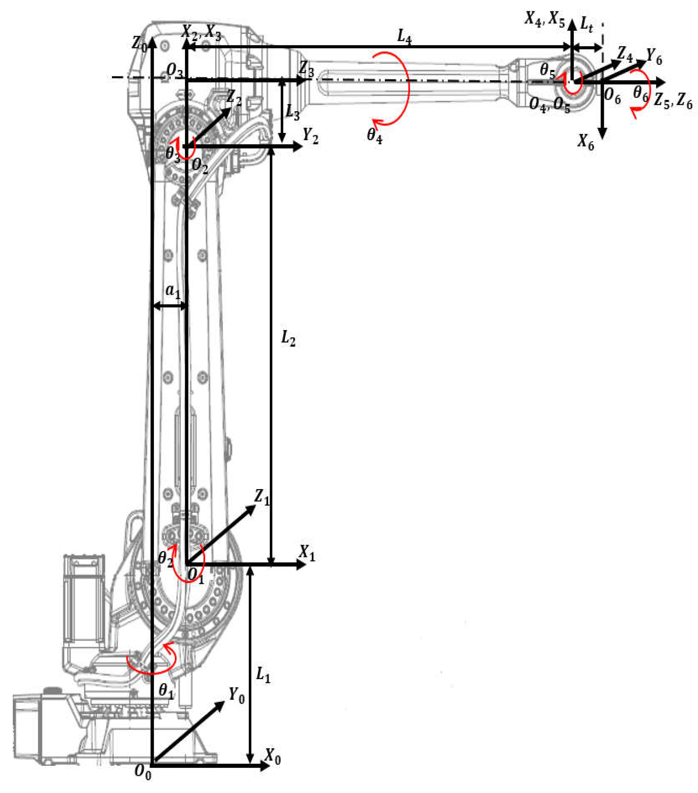
Figure A2.
Zed 2 stereo camera model with dimensions.
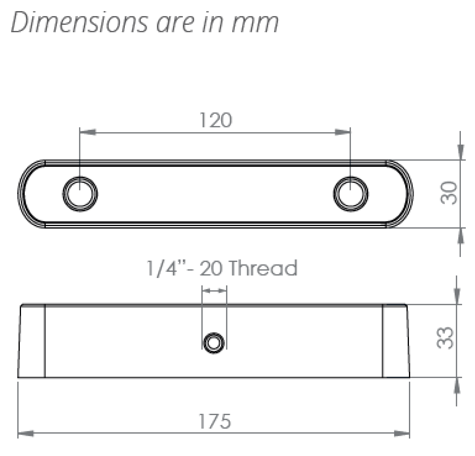

Table A1.
Specification Table of ABB IRB 4600 45/2.05 Model (Dimensions).
| Parameters | Values |
|---|---|
| Length of Link 1: | 495 mm |
| Length of Link 2: | 900 mm |
| Length of Link 3: | 175 mm |
| Length of Link 3: | 960 mm |
| Length of Link 1 offset: | 175 mm |
| Length of Spherical wrist: | 135 mm |
| Tool length (screwdriver): | 127 mm |
Table A2.
Specification Table of ABB IRB 4600 45/2.05 Model (Axis Working range).
| Axis Movement | Working range |
|---|---|
| Axis 1 rotation | +180 to -180 |
| Axis 2 arm | +150 to -90 |
| Axis 3 arm | +75 to -180 |
| Axis 4 wrist | +400 to -400 |
| Axis 5 bend | +120 to -125 |
| Axis 6 turn | +400 to -400 |
Table A3.
Specification Table of Stereo Camera Zed 2.
| Parameters | Values |
|---|---|
| Focus length: f | 2.8 mm |
| Baseline: B | 120 mm |
| Weight: W | 170g |
| Depth range: | 0.5m-25m |
| Diagonal Sensor Size: | 6mm |
| Sensor Format: | 16:9 |
| Sensor Size: W X H | 5.23mm X 2.94mm |
| Angle of view in width: | |
| Angle of view in height: | 55.35 |
Table A4.
Specification Table of Motors and gears.
| Parameters | Values |
|---|---|
| DC Motor | |
| Armature Resistance: | 0.03 |
| Armature Inductance: | 0.1 mH |
| Back emf Constant: | 7 mv/rpm |
| Torque Constant: | 0.0674 N/A |
| Armature Moment of Inertia: | 0.09847 kg |
| Gear | |
| Gear ratio: | 200:1 |
| Moment of Inertia: | 0.05 kg |
| Damping ratio: | 0.06 |
Appendix B
In this section, we will show forward kinematics and inverse kinematics of the 6 DoFs revolute robot manipulators. The results are consistent with the model ABB IRB 4600.
Forward kinematics refers to the use of kinematic equations of a robot to compute the position of the end-effector from specified values for the joint angles and parameters. The equations are summarized in the below:
where , and are the end-effector’s directional vector of Yaw, Pitch and Roll in base frame (Figure A1). And are the vector of absolute position of the center of the end-effector in base frame . For a specific model ABB IRB 4600-45/2.05 (Handling capacity: 45 kg/ Reach 2.05m) the dimensions and mass are summarized in Table A1.
Inverse kinematics refers to the mathematical process of calculating the variable joint angles needed to place the end-effector in a given position and orientation relative to the inertial base frame. The equations are summarized in the below:
where , , and have been defined above in the forward kinematic discussion.
References
- W. Chang and C.-H. Wu, “Automated USB peg-in-hole assembly employing visual servoing,” in Proc. 3rd Int. Conf. Control, Autom. Robot. (ICCAR). Nagoya, Japan: IEEE. Apr. 2017, pp. 352–355.
- J. Xu, K. Liu, Y. Pei, C. Yang, Y. Cheng, and Z. Liu, “A noncontact control strategy for circular peg-in-hole assembly guided by the 6-DOF robot based on hybrid vision,” IEEE Trans. Instrum. Meas., vol. 71,2022, Art. no. 3509815.
- W. Zhu, H. Liu, and Y. Ke, “Sensor-based control using an image point and distance features for rivet-in-hole insertion,” IEEE Trans. Ind. Electron., vol. 67, no. 6, pp. 4692–4699, Jun. 2020.
- F. Qin, D. Xu, D. Zhang, W. Pei, X. Han and S. Yu, "Automated Hooking of Biomedical Microelectrode Guided by Intelligent Microscopic Vision," in IEEE/ASME Transactions on Mechatronics, vol. 28, no. 5, pp. 2786-2798, Oct. 2023. [CrossRef]
- Jung, Woo, Jin., Lee, Hyun, Jung. (2020). Automatic alignment type welding apparatus and welding method using the above auto-type welding apparatus.
- P. Guo, Z. Zhang, L. Shi, and Y. Liu, “A contour-guided pose alignment method based on Gaussian mixture model for precision assembly,” Assem. Autom., vol. 41, no. 3, pp. 401–411, Jul. 2021.
- F. Chaumette and S. Hutchinson, “Visual servo control Part I: Basic approaches,” IEEE Robotics & Automation Magazine, vol. 13, pp. 82–90, 2006.
- Y. Ma, X. Liu, J. Zhang, D. Xu, D. Zhang, and W. Wu, “Robotic grasping and alignment for small size components assembly based on visual servoing,” Int. J. Adv. Manuf. Technol., vol. 106, nos. 11–12, pp. 4827–4843, Feb. 2020.
- T. Hao, D. Xu and F. Qin, "Image-Based Visual Servoing for Position Alignment With Orthogonal Binocular Vision," in IEEE Transactions on Instrumentation and Measurement, vol. 72, pp. 1-10, 2023, Art no. 5019010. [CrossRef]
- G. Flandin, F. Chaumette and E. Marchand, "Eye-in-hand/eye-to-hand cooperation for visual servoing," Proceedings 2000 ICRA. Millennium Conference. IEEE International Conference on Robotics and Automation. Symposia Proceedings (Cat. No.00CH37065), San Francisco, CA, USA, 2000, pp. 2741-2746 vol. [CrossRef]
- Muis, A., & Ohnishi, K. (n.d.). Eye-to-hand approach on eye-in-hand configuration within real-time visual servoing. The 8th IEEE International Workshop on Advanced Motion Control, 2004. AMC ’04. [CrossRef]
- Ruf, M. Tonko, R. Horaud, and H.-H. Nagel: “Visual Tracking of An End-Effector by Adaptive Kinematic Prediction”, Proc. of the Intl. ConJ on Intelligent Robots and Systems(IROS’97). vol. 2, pp.893-898,Grenoble, France, Sep.( 1997).
- Jose Luis de Mena: “Virtual Environment for Development of Visual Servoing Control Algorithms”, Thesis, Lund Institute Technology, Sweden, May, (2002).
- K. Irie, I. M. Woodhead, A. E. McKinnon and K. Unsworth, "Measured effects of temperature on illumination-independent camera noise," 2009 24th International Conference Image and Vision Computing New Zealand, Wellington, New Zealand, 2009, pp. 249-253. [CrossRef]
- Patidar, P., Gupta, M., Srivastava, S., & Nagawat, A.K. Image De-noising by Various Filters for Different Noise. International Journal of Computer Applications. 2010; 9: 45-50.
- Das, S., Saikia, J., Das, S., & Goñi, N. A COMPARATIVE STUDY OF DIFFERENT NOISE FILTERING TECHNIQUES IN DIGITAL IMAGES. 2015.
- R. Zhao and H. Cui. Improved threshold denoising method based on wavelet transform. 2015 7th International Conference on Modelling, Identification and Control (ICMIC); 2015: pp. 1-4. [CrossRef]
- Ng J., Goldberger J.J. Signal Averaging for Noise Reduction. In: Goldberger J., Ng J. (eds) Practical Signal and Image Processing in Clinical Cardiology. London: Springer; 2010. p. 69-77. [CrossRef]
- G. Chen, F. Zhu and P. A. Heng. An Efficient Statistical Method for Image Noise Level Estimation. In: 2015 IEEE International Conference on Computer Vision (ICCV); 2015.p. 477-485. [CrossRef]
- Mark, W.S., M.V. (1989). Robot Dynamics and control. John Wiley & Sons, Inc. 1989.
- W. W. MARZOUK, A. ELBASET etc. (2019).” Modelling, Analysis and Simulation for A 6 Axis Arm Robot by PID Controller”, International Journal of Mechanical and Production Engineering Research and Development (IJMPERD) ISSN (P): 2249-6890; ISSN (E): 2249-8001 Vol. 9, Issue 4, Aug 2019, pp. 363-376. [CrossRef]
- Li, R., & Assadian, F. Role of Uncertainty in Model Development and Control Design for a Manufacturing Process. In: Majid T., Pengzhong L, & Liang L, editors. Production Engineering and Robust Control. London: IntechOpen 2022. pp. 137-167. [CrossRef]
- Anonymous. ABB IRB 4600 -40/2.55 Product Manual [Internet]. 2013. Available from: https://www.manualslib.com/manual/1449302/Abb-Irb-4600-40-2-55.html#manual [Accessed: 2024-7-17].
- Anonymous. Stereolabs Docs: API Reference, Tutorials, and Integration. Available from: https://www.stereolabs.com/docs [Accessed: 2024-7-18].
- Peer, P., & Solina, F. (2006). Where physically is the optical center? Pattern Recognition Letters, 27(10), 1117–1121. [CrossRef]
- Vassilios D Tourassis, Dimitrios M Emiris. (1993) “A comparative study of ideal elbow and dual-elbow robot manipulators”, Mechanism and Machine Theory, Volume 28, Issue 3, Pages 357-373, ISSN 0094-114X. [CrossRef]
Figure 1.
Algorithm flowchart.
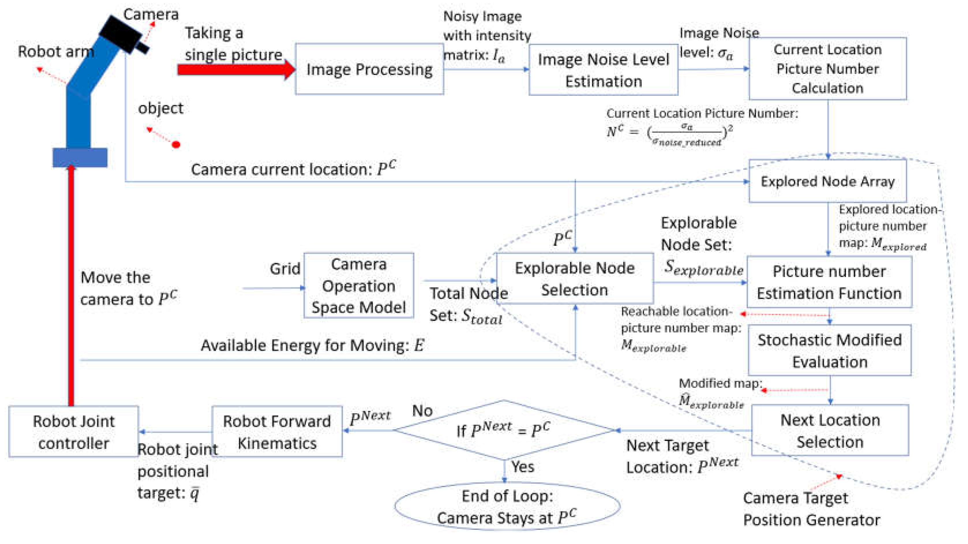
Figure 2.
(a): The operational space of the camera is an arbitrary closed 3D geometry in the space shown in the plot. The gridded area is in 3D (blue dashed lines). (b): Four initial nodes are chosen so that their connection lines (red dashed line) are perpendicular. The picture number of Node 5 can be estimated by Equation (1) from four initial explored nodes represents Euclidean distance (green line).
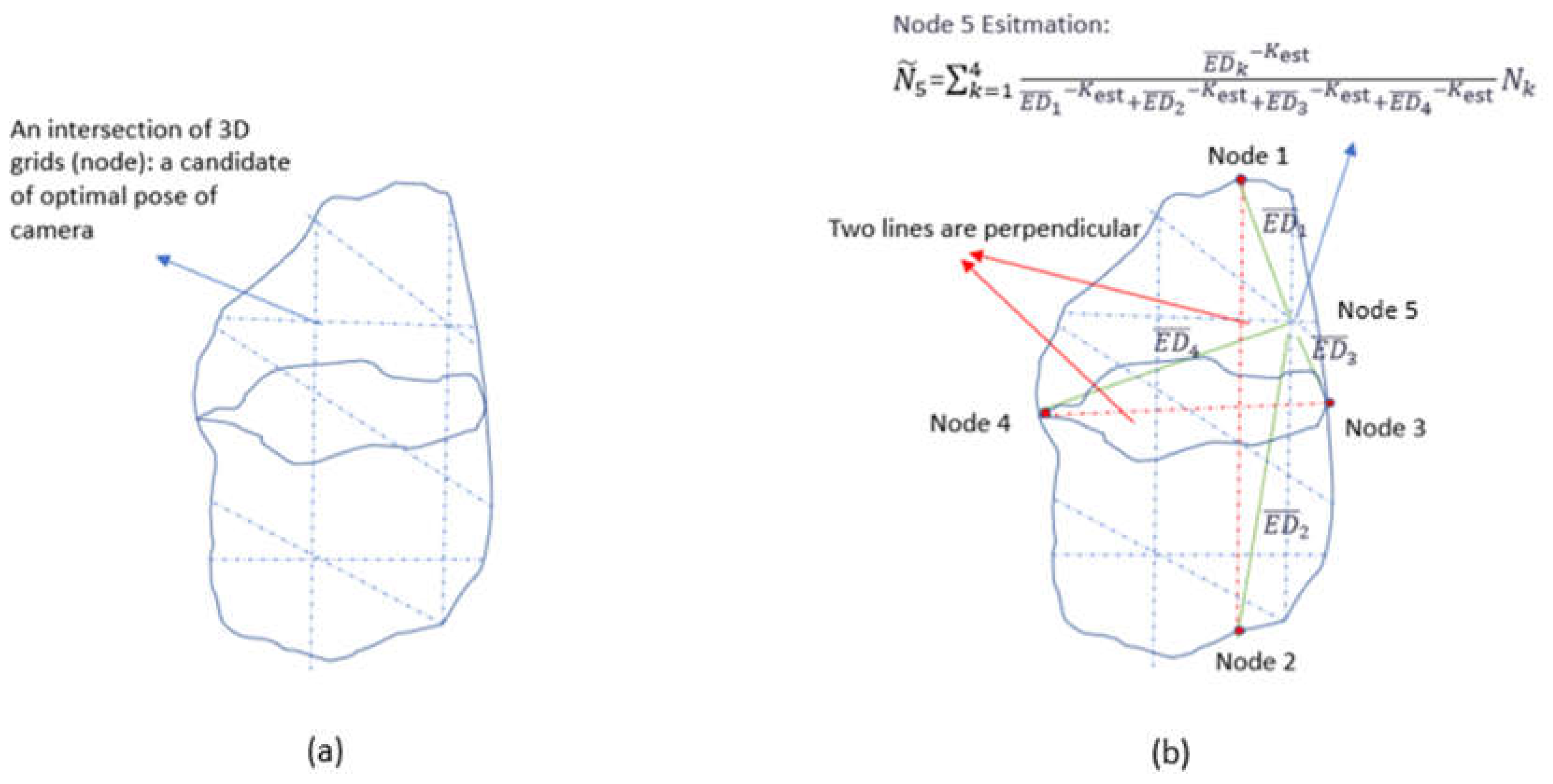
Figure 3.
Find the explorable set when the global minimum (red star) is inaccessible. (a). Step 1: Obtain the feasible range (green dashed line). (b). Step 2: Find the explored node with a minimum picture number in the feasible range. Initial nodes (blue stars) are explored (blue circles). is . (c). Step 3: Obtain explorable range when . The explorable range (blue dashed line) is a subset of .
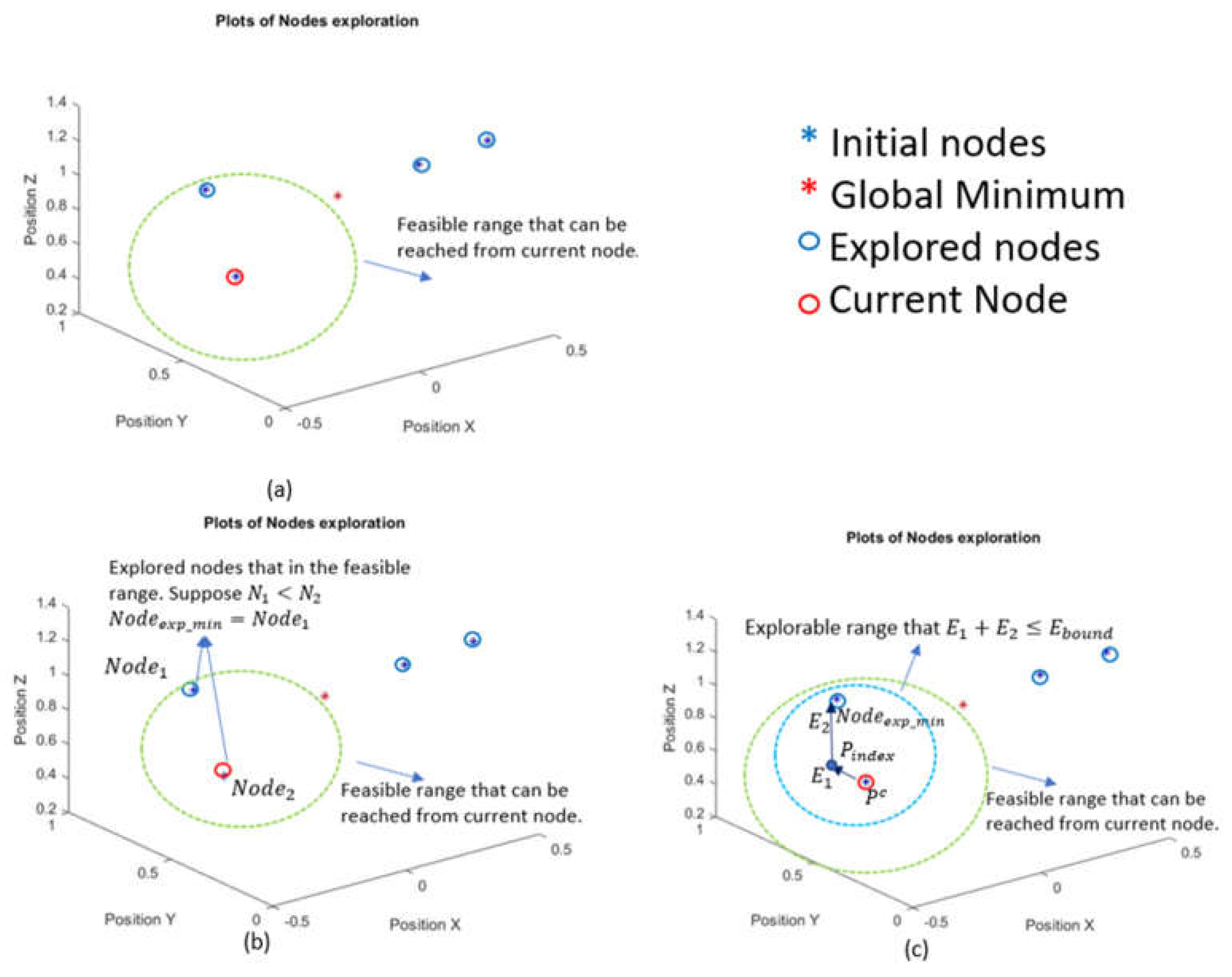
Figure 4.
Both case1 and case2 have the same estimated value of an unexplored node (green point) from Equation (1). However, the node in case 1 has a larger distance to explored nodes (red points) compared to that in case 2. Therefore, we set different standard deviations (
Figure 4.
Both case1 and case2 have the same estimated value of an unexplored node (green point) from Equation (1). However, the node in case 1 has a larger distance to explored nodes (red points) compared to that in case 2. Therefore, we set different standard deviations (
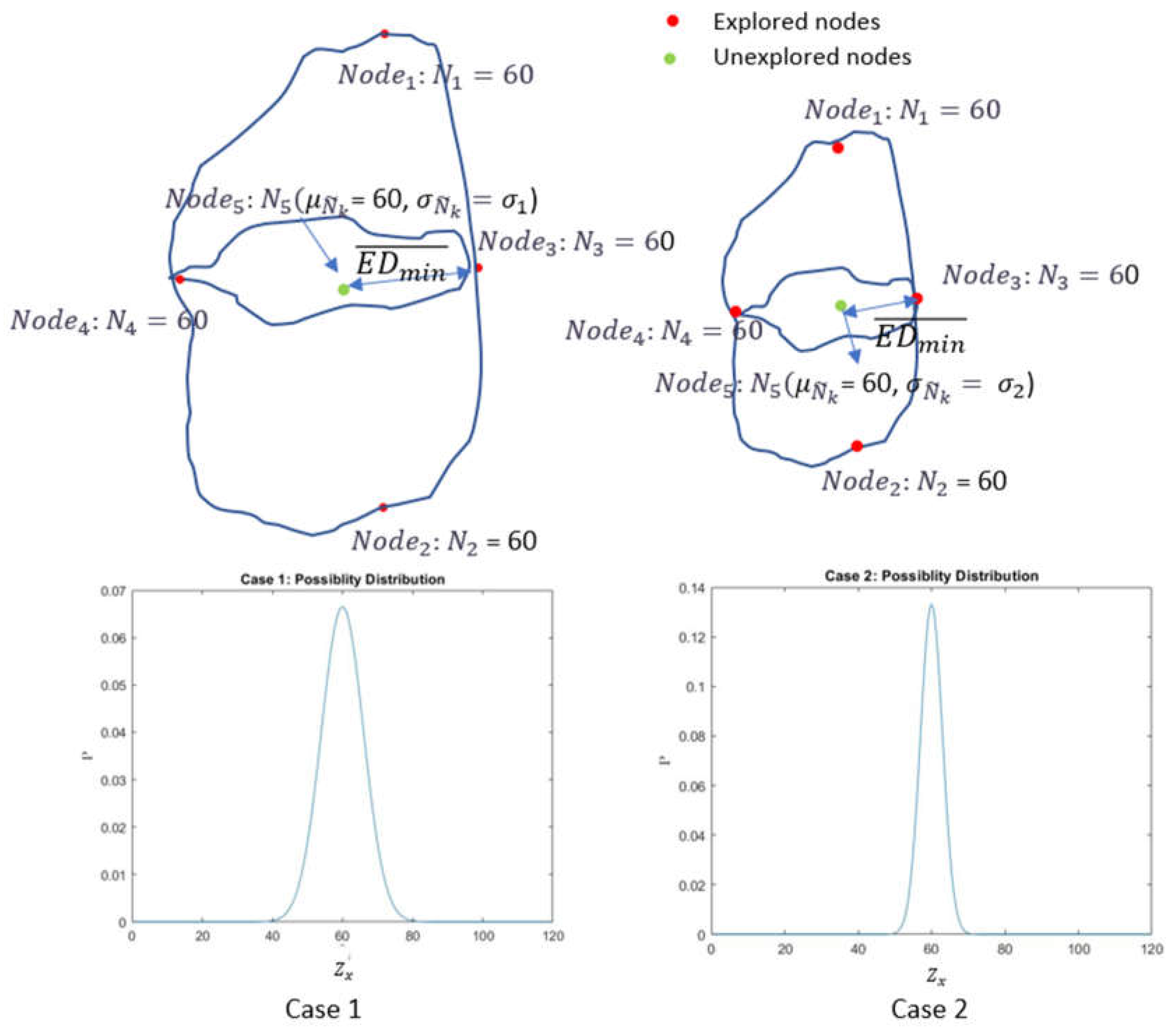
Figure 5.
The block Diagram of feedback linearization Youla control design used for the joint control loop.
Figure 5.
The block Diagram of feedback linearization Youla control design used for the joint control loop.
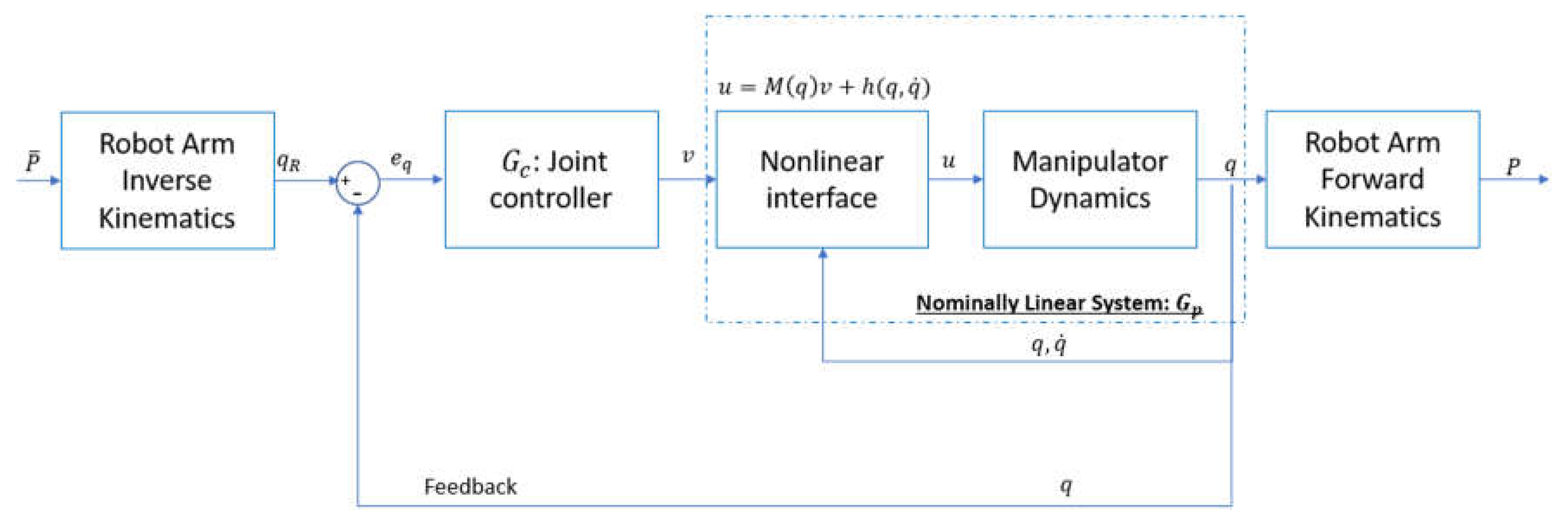
Figure 6.
Response of with varying .
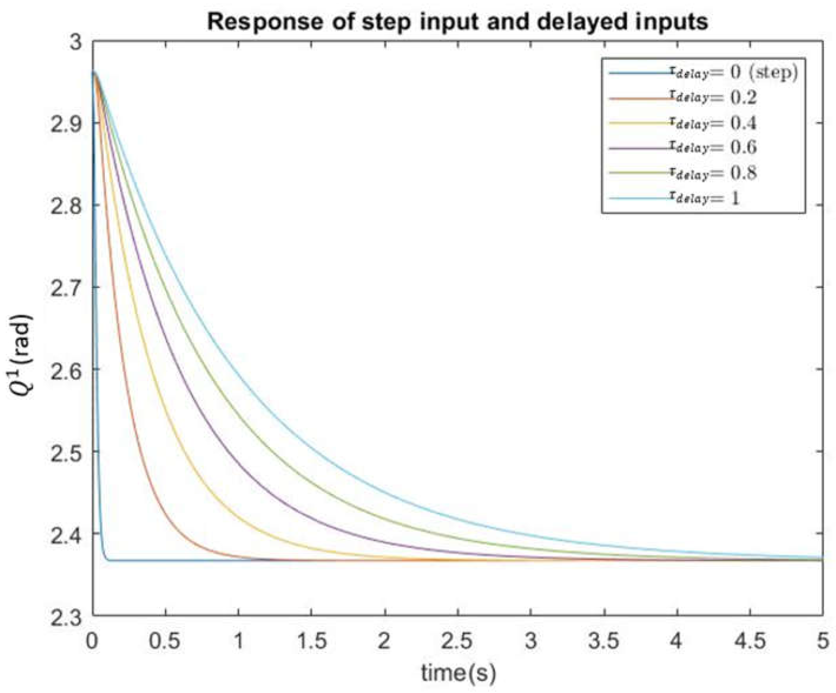
Figure 7.
The topology of the multi-robotic system for accurate positioning control.
Figure 8.
Spherical Wrist Model.
Figure 9.
Workspace of an Ideal Elbow Manipulator.
Figure 9.
The workspace configuration of the multi-robotic system.
Figure 10.
The Detectable Space of the Stereo Camera.
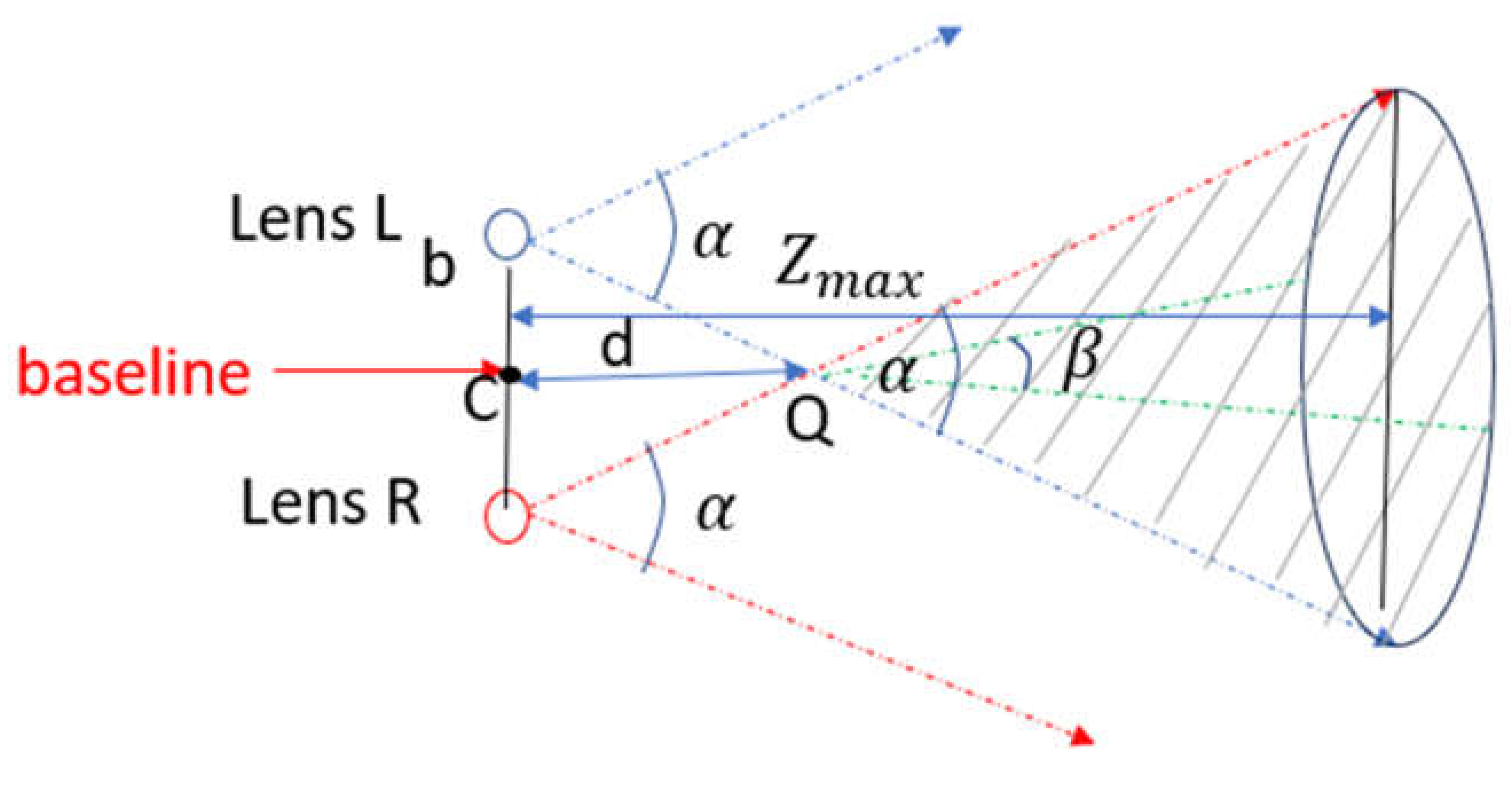
Figure 11.
The Detectable Elliptic Cone in the Inertial Visual System Frame.
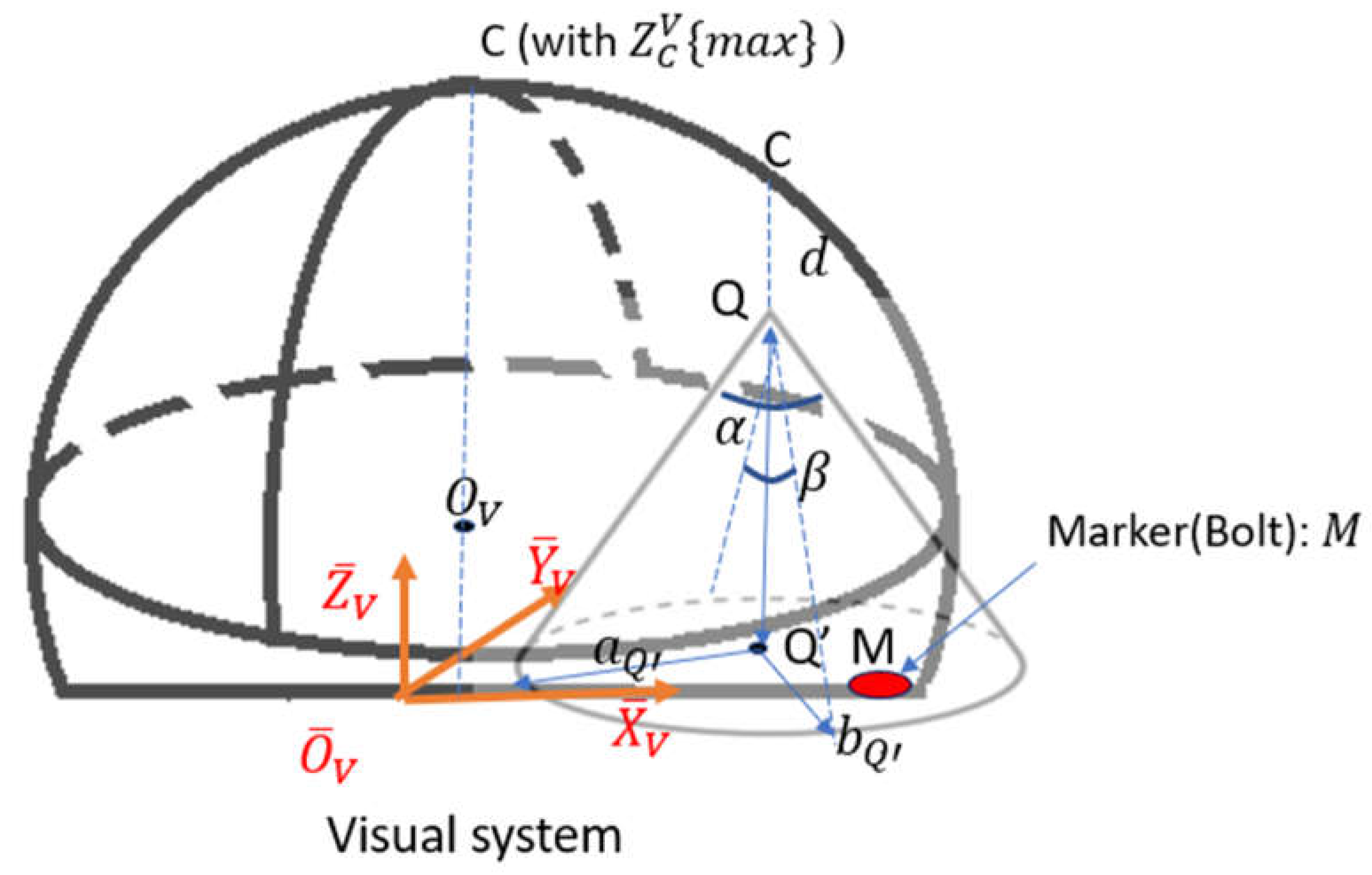
Figure 12.
Illustration of Camera Operational Space (the shaded area).
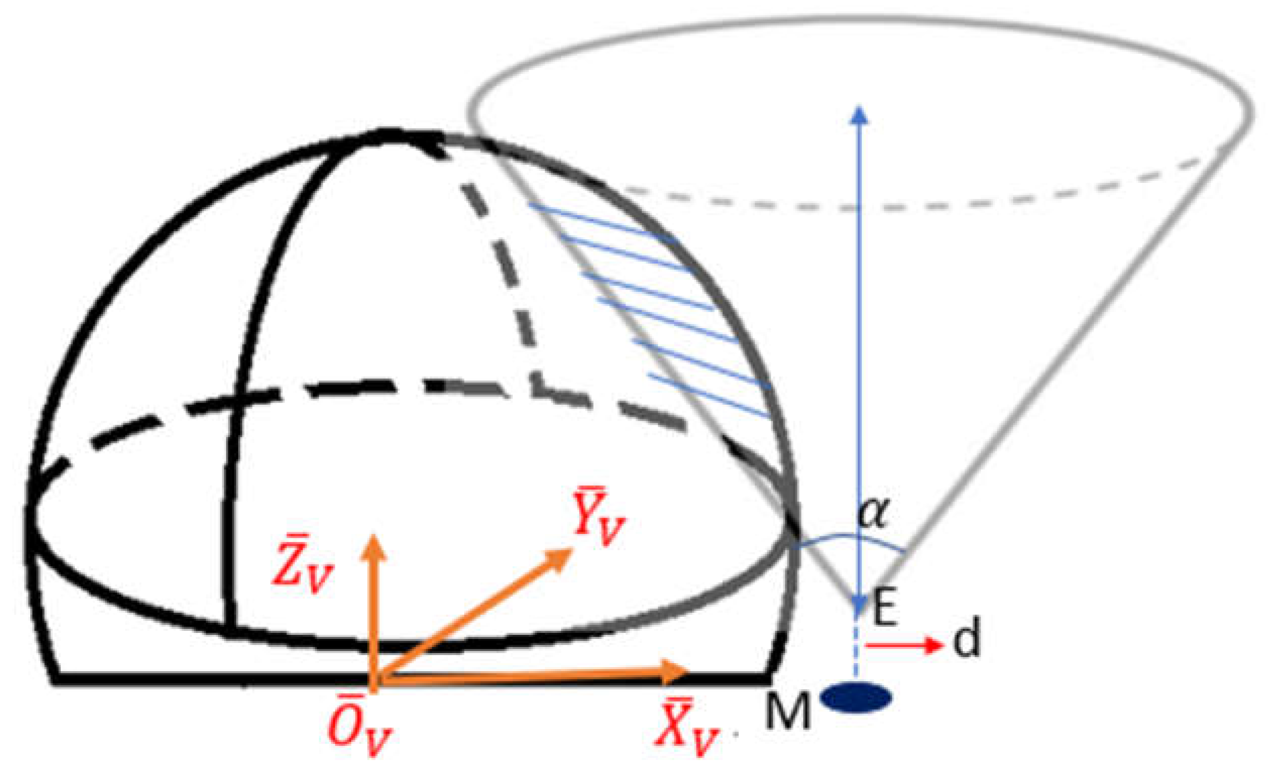
Figure 13.
An Extreme Case of Marker Position.
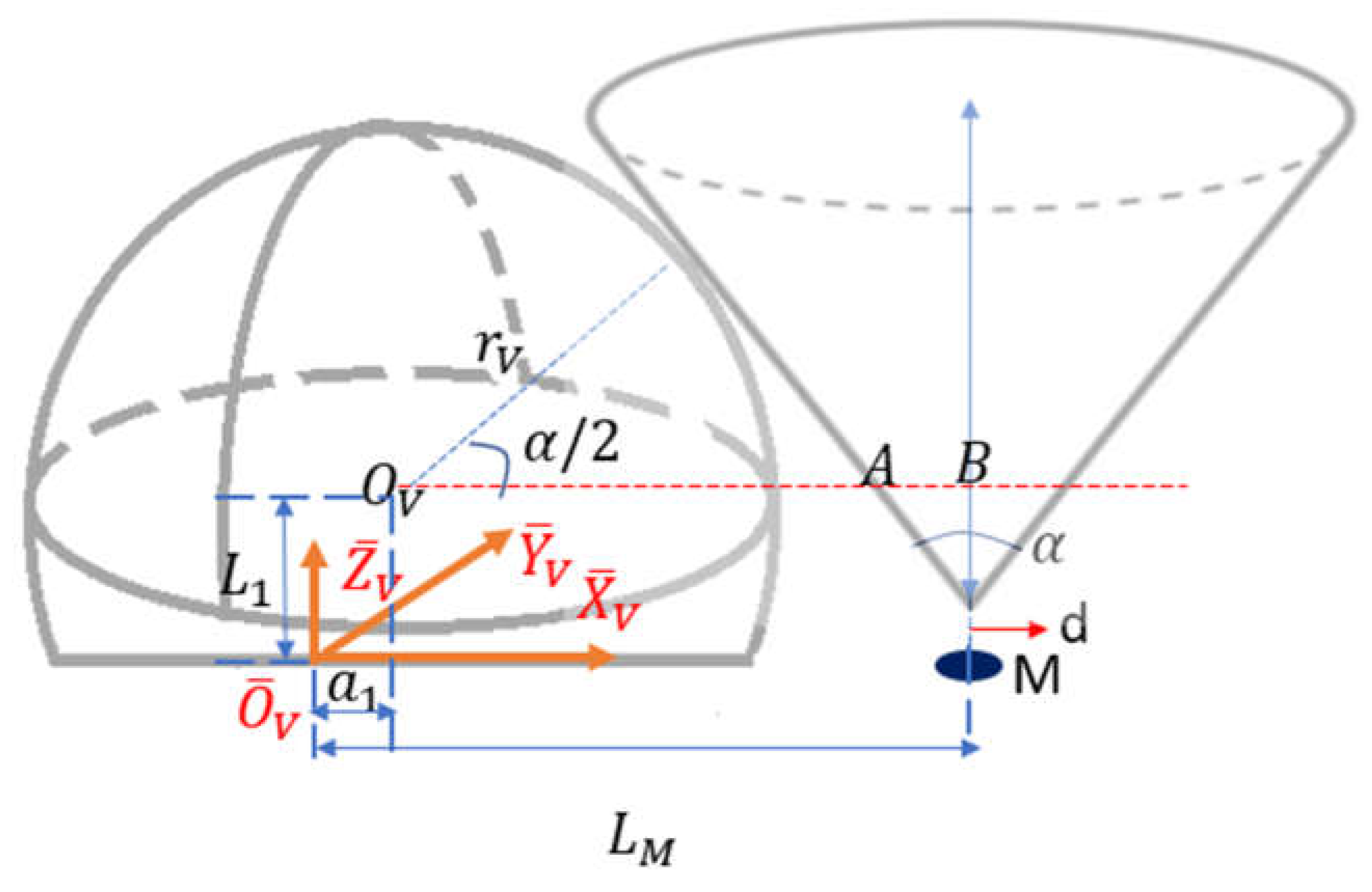
Figure 14.
The Camera Operational Space Cross-section at plane.
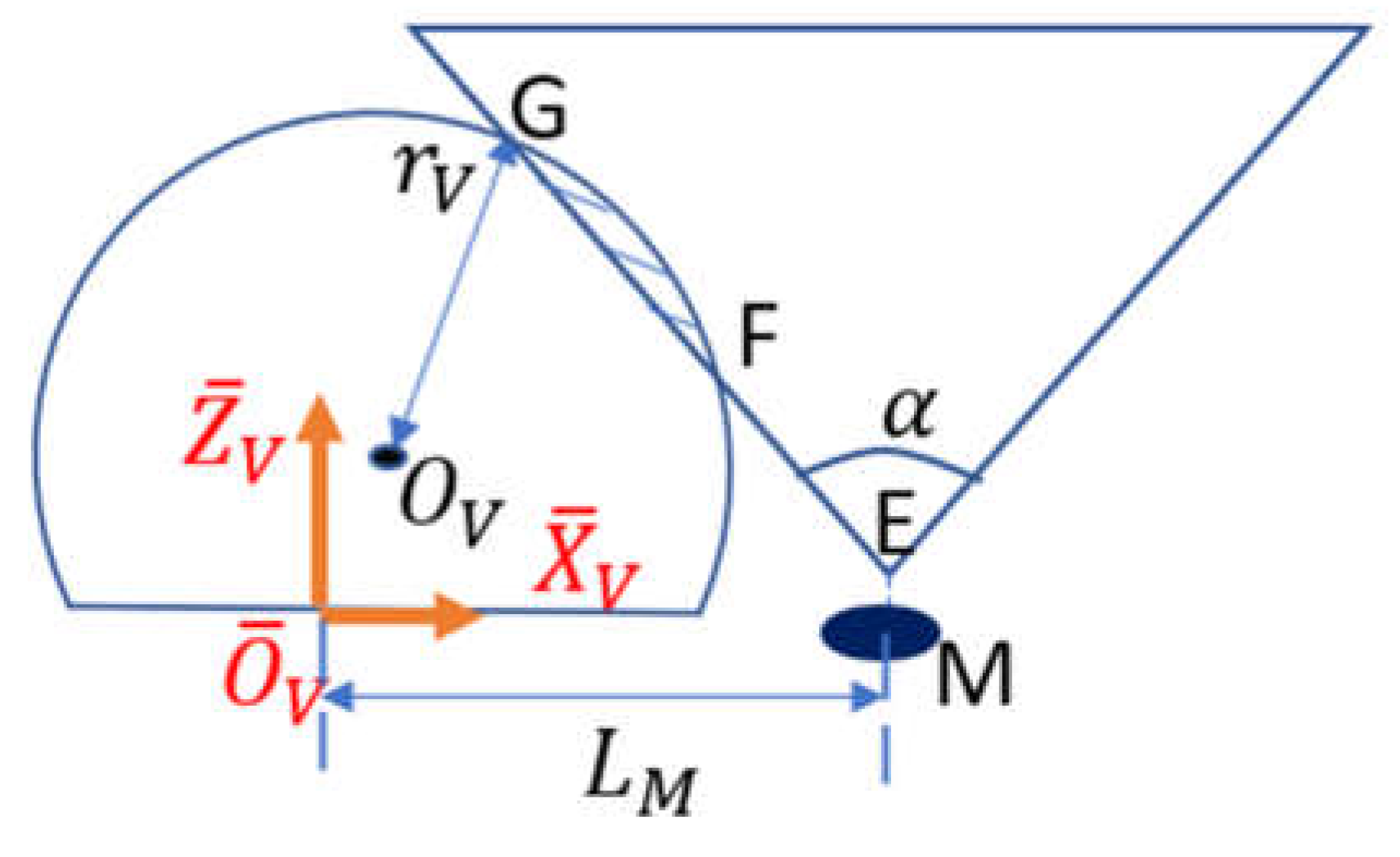
Figure 15.
The Camera Operational Space Cross-section at plane.
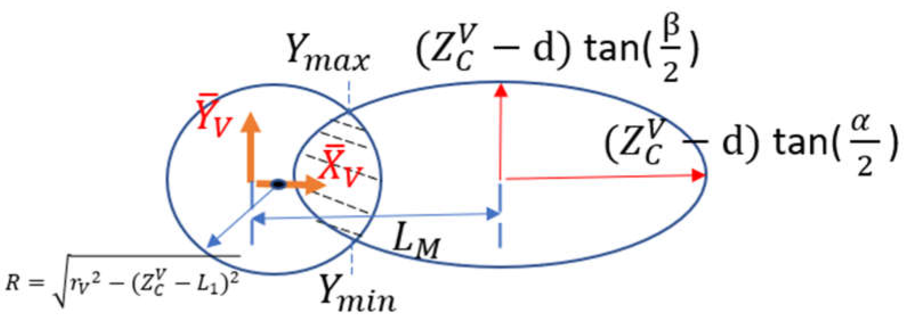
Figure 16.
Reduction of Nodes from the ideal to the realistic camera operational space.
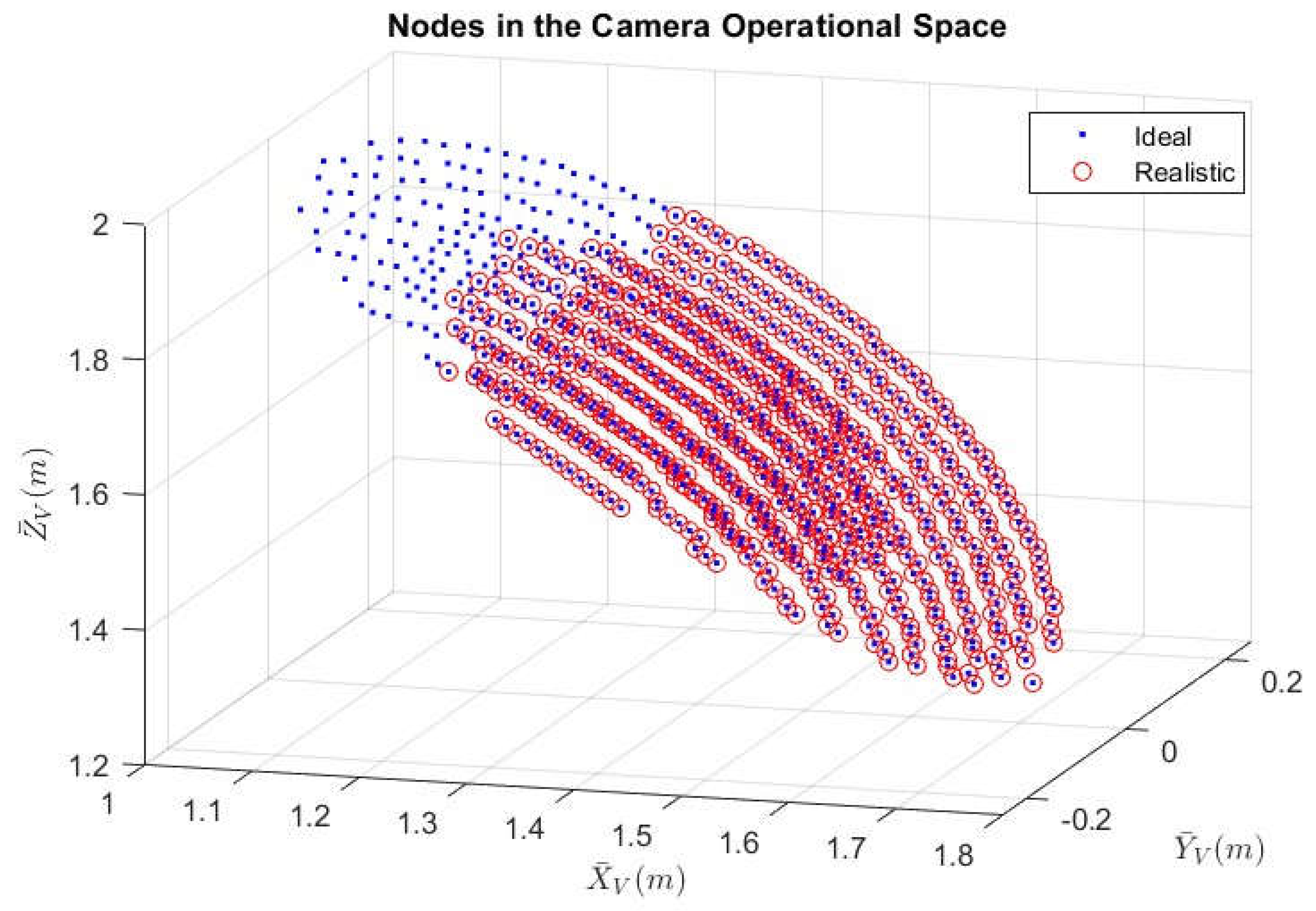
Figure 17.
Plots of sequential exploration with different .
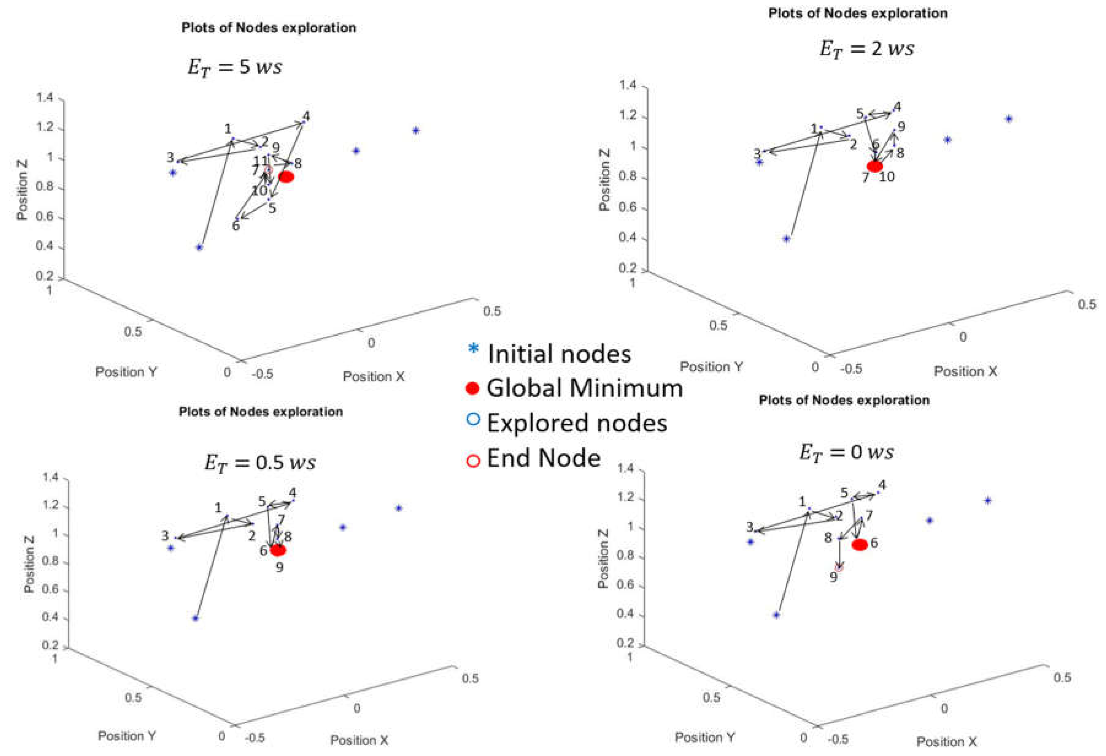
Table 1.
Estimated Energy Cost and Settling Time with Varying Delay Constant.
| [s] | [ws] | |
|---|---|---|
| 0 | 10.895 | 0.07 |
| 0.2 | 0.102 | 0.73 |
| 0.4 | 0.030 | 1.42 |
| 0.6 | 0.016 | 2.11 |
| 0.8 | 0.011 | 2.80 |
| 1 | 0.009 | 3.49 |
Note: is measured as [watts seconds]
Disclaimer/Publisher’s Note: The statements, opinions and data contained in all publications are solely those of the individual author(s) and contributor(s) and not of MDPI and/or the editor(s). MDPI and/or the editor(s) disclaim responsibility for any injury to people or property resulting from any ideas, methods, instructions or products referred to in the content. |
© 2024 by the authors. Licensee MDPI, Basel, Switzerland. This article is an open access article distributed under the terms and conditions of the Creative Commons Attribution (CC BY) license (http://creativecommons.org/licenses/by/4.0/).
Copyright: This open access article is published under a Creative Commons CC BY 4.0 license, which permit the free download, distribution, and reuse, provided that the author and preprint are cited in any reuse.


