
Submitted:
22 August 2024
Posted:
23 August 2024
You are already at the latest version
Abstract
Steel surface protection with hard coatings is essential in the metalworking industry, yet developing high-performance hard coatings still remains a challenge. Quaternary nitride coatings, particularly TiAlSiN, have been extensively studied, but commercial TiAlSiN coatings vary widely, and there is a lack of consistent data. This study presents findings on the development and evaluation of TiAlSiN and TiAlSiN/TiN thin films, with an 800 nm thick TiAlSiN top coating and a 100 nm thick TiN mid-coating. The films were deposited on C120 tool steel discs via reactive DC magnetron sputtering. Ti and TiAlSi 75–20–5 (at.%) disc-shaped targets (50.8 mm diameter × 6.3 mm thickness), fabricated by our team through spark plasma sintering, were used for the sputtering process. Coatings were grown on smooth steel substrates heated to 300 °C, resulting in a uniform micro-structure with nanoparticles of globular (TiN) or pyramidal shape (TiAlSiN), as evidenced by SEM analysis. Nanoindentation tests showed superior mechanical properties for all coatings compared to the steel substrate. Micro-scratch tests indicated better scratch resistance for TiAlSiN/TiN bilayer (BL) coatings than for TiAlSiN single-layer (SL) coatings. Electrochemical impedance spectroscopy tests in a 3.5 wt.% NaCl solution revealed that the BL coatings demonstrated superior corrosion resistance compared to the SL coatings, even after thermal aging at 800 °C for 1 hour. The superior properties of the synthesized TiAlSiN/TiN films recommend them as protective coatings for tool steel surfaces.
Keywords:
magnetron sputtering
; TiAlSiN and TiN thin film coatings
; microstructure
; mechanical
; tribological and electrochemical properties
; protection properties
1. Introduction
Metal cutting tools can experience during operation various types of wear during operation, including abrasive wear, adhesive wear (cold welding), cracking, breaking, chipping, and plastic deformation [1,2,3]. Abrasive and adhesive wear primarily affect the surface, while cracking, breaking, chipping, and plastic deformation occur within the bulk of the material. Contact fatigue wear is influenced by microscopic defects in the homogeneity of the materials and surface imperfections from mechanical processing or wear [2,3]. All these wear modes can occur due to interactions between the cutting tool, the workpiece, and the environment [1,4]. To mitigate this, wear-resistant coatings are used, allowing for tailored bulk and surface properties based on the specific application.
The wear resistance of a surface can be enhanced by changing either the surface material or its topography. This can be achieved through thermal or chemical treatments or by applying a new material with distinct properties. The new surface layer may be a uniform single layer, a multilayer structure with varying properties in each layer, a functionally graded structure with gradually changing material properties, or a composite layer incorporating a matrix from one material with elements like particles from another material, along with phases reflecting the properties of the included materials [5].
The functionalization treatment of the surfaces of metal cutting tools with wear-resistant coatings can lead to improved operational behavior, increased performance and appearance quality, extended lifespan, and reduced material consumption. Solutions for preventing abrasive and adhesive wear on the cutting tools must consider the nature and properties of the metal substrate (e.g., tool steel), the selection of heat treatments, the condition of the tool surfaces, and the application of hard wear-resistant coatings [6].
Hard, wear-resistant coatings applied to tool steel substrates, whether in single or multi-layers, must possess the following key characteristics: high hardness and toughness for load-bearing capacity, excellent scratch resistance, strong adhesion and cohesion to prevent detachment or layer slippage, thermal and chemical stability with high corrosion resistance, a low friction coefficient to reduce heating and wear, good uniformity with minimal defects and porosity to prevent pitting corrosion, and high thermal conductivity.
For tool steel components such as dies and punches, it is necessary that the surfaces of the components without or with wear-resistant protective coatings do not adhere to each other. For hard wear-resistant protective coatings, thermal stability is very important because the coatings are exposed to high temperatures during dry mechanical processing. The adhesion of the coatings to the substrate is mainly influenced by the temperature, flatness, and surface roughness of the substrate.
Surface hardening includes various techniques like physical vapor deposition (PVD), chemical vapor deposition (CVD), and thermo-chemical methods, where coatings are formed through diffusion between the coating material and the substrate [7,8,9]. The most commonly used methods are PVD techniques, including magnetron sputtering (DC and RF), reactive sputtering with gases like nitrogen or oxygen [8,10,11,12,13], arc ion plating [14,15,16], thermal vacuum evaporation [9], and plasma spraying [17,18].
Among the deposition materials used for obtaining hard, wear-resistant protective and decorative coatings are Ti alloys, such as TiAl, TiSi, TiCr, TiB, TiZr, TiAlSi, etc. Thin layers of TiC, TiCN, TiN, and Al₂O₃ produced by CVD methods during the 1970-1975 period were the first coatings successfully used on an industrial scale to increase the performance of metal cutting tools subjected to wear. Since the 1980s, TiN and TiCN coatings have been developed by PVD methods, followed by TiAlN coatings in the 1990s, and starting in 2007, TiAlSiN, AlTiSiN, and AlCrSiN coatings have been developed [19].
Wear-resistant thin film coatings have thicknesses of up to 12 µm and are mainly used as hard or tribological protective layers for metal cutting tools, but also for plastic deformation tools, bearings, sealing elements, and as coatings resistant to corrosion and erosion. The hardness, coefficient of friction, oxidation resistance, chemical stability, and adhesion of the coating play an important role in the processing of difficult-to-machine materials in dry environments, as it is desirable that the hardness and thermal conductivity of the substrate do not deteriorate, and also to avoid galling and thermal diffusion.
The chemical composition of deposition materials varies significantly based on the manufacturer and intended application. For instance, adding 25–75 at.% Al to TiAl alloys enhances mechanical strength, crack resistance, and elastic modulus while reducing density. Al also increases the allotropic transformation temperature of Ti. In TiAl alloys, adding 5–9 at.% of elements like Si, Cr, Nb, Mo, and W improves oxidation and creep resistance, thermal stability, and mechanical and tribological properties. The quality of coatings is strongly influenced by the chemical composition of the deposition materials, the equipment used, and the working parameters [1,2,20]. Thus, selecting the adequate deposition material and technological process for creating wear-resistant coatings must take into account the properties of the substrate material and its envisaged application.
The performance of protective coatings applied in single or multilayers with binary (e.g., TiN, CrN), ternary (e.g., TiAlN, TiCrN, TiSiN), or quaternary (e.g., TiAlSiN, TiAlCrN, TiCrSiN) compositions on steel tools is influenced by several factors. These include the geometry and quality of the substrate surface, the mechanical and thermal treatments applied to the substrate before and after deposition, as well as the type, composition, structure, and thickness of the coating [21,22,23,24]. Studies have shown that multi-layer and compositional gradient coatings exhibit enhanced structural characteristics, along with superior mechanical and wear-resistant properties, compared to single-layer coatings, effectively meeting specific application requirements [1,10,13,23,25].
TiN hard ceramic coatings are widely used to enhance the surface properties of metallic alloys, steels, and carbides. However, applying TiN coatings requires high substrate temperatures to achieve sufficient adhesion strength, and the coatings begin to oxidize at around 550 °C [26]. These limitations have led researchers to explore ternary and quaternary coatings, such as TiAlN, TiSiN [6,7,20], and TiAlSiN [11,27,28], which can provide improved oxidation resistance up to 950 °C.
Although TiAlN and TiSiN coatings exhibit good mechanical properties and maintain oxidation resistance up to 700 °C, their adhesion can diminish at higher temperatures, potentially leading to failures during operation [7]. Fuentes et al. [27] investigated the wear behavior of TiAlSiN coatings up to 600 °C and found that the coating composition and testing temperature significantly influence the tribological behavior. Given that the operating temperature for high-speed dry cutting with TiAlSiN-based coated tools often exceeds 600 °C, further in-depth research into the mechanical and tribological properties of TiAlSiN coatings at elevated temperatures is necessary [7,14,28].
Zhou et al. [14] prepared TiAlSiN coatings using cathode arc ion process with Ti, Al0.67Ti0.33 and Ti0.8Si0.2 targets. They studied the microstructure, mechanical properties, and tribological behavior of these coatings at room temperature (RT) and after annealing at 200 °C, 400 °C, 600 °C, and 800 °C. Their findings revealed that annealing temperature significantly influenced the elemental composition, particularly with an increase in oxygen content as the annealing temperature increased. Additionally, the formation of oxides such as Ti-O, Al-O, and Si-O on the coatings acted as lubricants, reducing the shear resistance and coefficient of friction for TiAlSiN coatings annealed above 600 °C.
Rahman et al. [29] deposited TiAlSiN thin films with an empirical formula of Ti0.5Al0.2Si0.05N0.5 and a thickness of about 200 nm on AISI M2 high-speed tool steel substrates using magnetron sputtering, with Ti, Al, and Si targets in an Ar + N₂ atmosphere. The as-deposited films exhibited an elemental composition (in at.%) of 20.31 % Ti, 18.23 % Al, 2.57 % Si, 25.64 % N, 13.13 % C, and 20.12 % O, as determined by X-ray photoelectron spectroscopy (XPS). The TiAlSiN films also demonstrated good structural and morphological stability after annealing in air at elevated temperatures up to 800 °C.
Many research studies utilize commercial sputtering targets made of pure Ti, Al, Si, as well as TiAl, AlSi, and TiAlSi alloys to deposit TiAlSiN thin film coatings via reactive magnetron sputtering on various substrates, such as AISI H11 (1.2343) hot work tool steel [30], AISI M2 high-speed steel [25], Si (100) and WC steel substrates [13], and cemented carbide (WC-Co, grade 6110) [31].
This study presents research results on TiAlSiN-based coatings deposited on C120 tool steel substrates using reactive DC magnetron sputtering. To achieve this, innovative TiAlSi and Ti targets, which we manufactured via spark plasma sintering under vacuum, were used as deposition materials. These targets enabled the deposition of TiAlSiN and TiAlSiN/TiN thin film coatings with higher and more stable deposition rates over the long term, as well as improved properties of the deposited films. The investigation of the microstructure, mechanical, tribological, and electrochemical properties of the as-deposited and thermally treated coatings, after exposure to air at 800 °C for 1 hour, led us to conclude that the TiAlSiN/TiN coatings are suitable as protective coatings for tool steel surfaces.
2. Materials and Methods
2.1. Materials
Disc-shaped samples of C120 tool steel, equivalent to 205Cr115 and X210Cr12 (1.2080), with diameter × thickness of 28 mm × 1 mm and 14 mm × 1 mm, respectively, were used as substrates for thin film deposition. This tool steel grade has the following chemical composition (wt.%): 1.9–2.2 % C, 0.1–0.4 % Si, 0.15–0.45 % Mn, 11–12 % Cr, max. 0.35 % Ni, and Fe balance, according to the standard EN ISO 4957:2018 [32].
Disc-shaped metallic targets of TiAlSi 75–20–5 (at.%) and Ti fabricated by our team (INCDIE ICPE-CA Bucharest, Romania) using spark plasma sintering (SPS) as described elsewhere [33,34], were employed for the sputtering process. The main technical characteristics of the SPSed sputtering targets are summarized in Table 1 [33,34].
2.2. Steel Substrate Preparation
The steel substrate samples were cut by electroerosion from cylindrical bars with a diameter of 14 mm and 28 mm. Afterwards, the steel samples were ground to obtain disc-shaped samples with flat parallel surfaces and a thickness of 1 mm. The surfaces of the steel samples were chemically cleaned with orthophosphoric acid, then the samples were washed with distilled water, afterwards in an alkaline solution of 1% w/v Na2CO3·10H2O, then the samples were washed again with distilled water and acetone. After that, the surfaces of the steel substrates were polished to a mirror finish with alumina, using a LaboPol5 (Struers) grinding machine. After polishing, the steel substrate samples were washed with distilled water, then with ethyl alcohol.
2.3. Thin Film Deposition
The deposition of TiAlSiN and TiN thin film coatings on C120 steel substrates was carried out by DC magnetron sputtering using a vacuum installation (Bestec, Germany) with SPSed TiAlSi 75–20–5 at.% and Ti sputtering targets (Table 1). The steel substrate samples, loaded onto the clamping device and rotation system of the deposition installation, were rotated at 10 rpm and heated to 300 °C at a heating rate of 30 °C/min. The following deposition conditions were used: Ar gas flow of 15 sccm, N2 gas flow of 7 sccm, start vacuum pressure of 10-6 mbar, working vacuum pressure of (1.5–2) × 10-2 mbar, initial power of 50 W, and deposition power of 200 W. The deposition rate was 0.08–0.16 Å/s for TiN films and 0.24–0.40 Å/s for TiAlSiN thin film coatings. The deposition duration was about 1.5 hours for TiN films and 8 hours for TiAlSiN coatings, achieving a film thickness of 100 nm for the TiN layer and 800 nm for the TiAlSiN top layer. The deposition rate and layer thickness were monitored in real time with a system consisting of an FTM-2000 controller (Torr International Inc., USA), an oscillator, a quartz crystal sensor with gold contacts resonating at 6 MHz (type IAD 6MHz Au, Evatec) mounted in the vacuum chamber close to the samples, and a controller-oscillator connection cable.
The single-layer TiAlSiN coatings were coded as SL, and the bilayer TiAlSiN/TiN coatings as BL. Several samples underwent thermal treatment in air at 800 °C for 1 hour using a N7/H oven (Nabertherm GmbH, Germany) to study the aging behavior in terms of mechanical, tribological and electrochemical properties. The thermally treated samples were coded as SL TT and BL TT, respectively.
2.4. SEM and EDS Analysis
SEM and EDS analysis of the TiAlN-based coatings was performed using an Auriga Field Emission Scanning Electron Microscope(FESEM) (Carl Zeiss, Oberkochen, Germany), equipped with a Canion focused ion beam (FIB) column (Orsay Physics, Fuveau, France), and a X-MaxN Energy Dispersive Spectroscopy(EDS) Silicon Drift Detector (SDD) sensor with Aztec software (Oxford Instruments plc, Abingdon, UK). The SEM images and EDS data were conducted at magnifications of 50,000× and 100,000×, and an acceleration voltage of 5 kV or 10 kV.
2.5. Mechanical Tests
2.5.1. Nanoindentation Testing
The mechanical properties such as indentation hardness (HIT), Vickers hardness HV, indentation elastic modulus (EIT), effective elastic modulus (E*), elastic reverse and plastic deformation work of indentation (Welast and Wplast), and elastic part of indentation work (ηIT) of the TiAlN-based coatings and the C120 steel substrate with diameter × thickness of 28 mm × 1 mm were determined by instrumented nanoindentation testing using the Oliver & Pharr calculation method [35], accordance to the ISO standards 14577-1:2015 [36] and 14577-4:2016 [37].
The nanoindentation tests were conducted at RT (25 ± 2 °C) with a relative humidity of 35 ± 3%, using the nanoindentation module (NHT2) and a diamond Berkovich indenter mounted on the compact platform of the Micro-Combi Tester (MCT2) (CSM Instruments, Peseux, Switzerland), under the conditions mentioned in Table 2. Each sample underwent 10 measurements in advanced mode, depth control (maximum depth of 1/10 of coating thickness) for the measurements of coatings, and load control for the measurements of the steel substrate, with the mean values and their standard deviation (SD) values being reported.
2.5.2. Micro-Scratch Tests
Micro-scratch tests of the TiAlSiN-based coatings deposited on C120 steel substrates with diameter × thickness of 28 mm × 1 mm were performed using the micro-scratch module (MST2) and a Rockwell diamond indenter with a radius of 100 µm, along with a video microscope with an objective lens with magnification of 20×, and specific sensors for measuring acoustic emission (AE), penetration depth (Pd), and coefficient of friction, all mounted on the compact platform of the Micro-Combi Tester (MCT2) (CSM Instruments, Peseux, Switzerland). The micro-scratch tests were conducted according to the standards ASTM C1624-22 [38] and ISO 20502:2005 [39], and involved determining the critical loads (Lc), which are the smallest loads at which visible defects appear in the investigated coating samples that were scratched at RT (25 ± 2 °C) with the Rockwell diamond indenter, under the following conditions: linear progressive scratching load from 0.03 N to 30 N, constant scratching speed of 6 mm/min, scratch length of 3 mm, loading rate of 60 N/min, and a scanning contact load of 30 mN. The optical, Pd and AE critical loads were determined from the recorded curves and images acquired through optical analysis of the scratch tracks using the Panorama option of the data acquisition software.
2.6. Tribological Tests
Tribological tests to determine the coefficient of friction (COF) at dry sliding and the specific wear rate were performed on TiAlSiN-based coatings/steel and C120 steel substrate with a diameter of 28 mm and a height of 1 mm at RT (25 ± 2 °C) with a relative humidity of 35 ± 3%, using a pin/ball-on-disk tribometer equipped with a rotating module (CSM Instruments, Switzerland) under the following conditions: a constant normal load (Fn) of 5 N (deadweight) applied to the tested sample, a static partner of a Ø6 mm alumina (Al2O3) ball held in contact with the rotating disc-shaped sample by the Fn, a constant linear speed of 3 cm/s, a sliding radius (R) of 9 mm, and a sliding distance (D) of 50 m (about 885 laps).The Al2O3 ball featured a Vickers hardness HV30 of 1970, and elastic modulus of 300 GPa [40,41]. The tribological tests were conducted according to the standard ASTM G99-17 [42] using an unworn ball for each test. The deflection of the static partner was measured for load and recorded as a tangential load (Ft). The coefficient of friction (µ) was calculated as the ratio of Ft to Fn using Equation (1) [43]:
The plots for variation in coefficient of friction (µ) were recorded as a function of sliding distance. The specific wear rate (Ws), expressed in mm³/(N·m), was calculated by measuring the volume of track material removed (V, in mm3) and normalizing that to the load (Fn, in N) and the sliding distance (D, in m) performed during the tribological test, as shown in Equation (2) [43]:
After completing the tribological test, each sample was examined using a Surtronic S25 contact profilometer (Taylor Hobson Ltd., Leicester, UK) equipped with a right-angle pick-up and a 5 µm stylus tip radius. A line scan was performed across the worn track over an evaluation length of 4 mm, with a cut-off of 0.8 and a Gaussian filter. The volume of material removed from the track was calculated by multiplying the area of the recorded wear track profile by the circumference of the wear track [43]. The profilometer was connected to the CSM tribometer and its data acquisition system to calculate the Ws values.
2.7. Corrosion Tests
Corrosion tests were performed using open-circuit potential (OCP), potentiodynamic polarization (PDP), and electrochemical impedance spectroscopy (EIS). The corrosion testing solution (electrolyte) used was a 3.5 wt.% NaCl aqueous solution.
Electrochemical studies were conducted with a Voltalab 40 Radiometer Analytical potentiostat/galvanostat interfaced with a computer, using VoltaMaster 4.0 software for data acquisition and processing. The experiments were carried out at RT (25 ± 2 °C) in a three-electrode electrochemical cell. The working electrode was the studied sample (the exposed surface in the 3.5 wt.% NaCl solution was circular with a diameter of 8 mm, and surface area of about 50.27 mm2), the auxiliary electrode was a platinum mesh electrode, and the reference electrode was a saturated Ag/AgCl electrode directly immersed in the electrolyte. All potentials are reported relative to this reference electrode.
Before the polarization and EIS measurements, the working electrode was kept in the 3.5 wt.% NaCl solution for 20 minutes to reach the OCP. The PDP experiments were performed at a scan rate of 1 mV/s, starting from a cathodic potential in the anodic direction, within the potential range of -800 mV to +800 mV versus OCP.
The EIS method studies the response of the system to the application of a small amplitude alternating current signal, which contains information related to the interface and the reactions occurring at the interface. Therefore, the EIS measurements were carried out at the open-circuit potential (EOC) in the frequency range of 100 kHz to 100 mHz with a sinusoidal potential perturbation of 10 mV in amplitude. The electrochemical parameters obtained from processing the PDP curves included the corrosion potential (Ecorr), corrosion current density (icorr), anodic and cathodic Tafel slopes (βa and βc, respectively), and polarization resistance (Rp), which were determined by Tafel extrapolation of the linear regions. The impedance parameters evaluated from the Nyquist plots recorded at the OCP included the charge transfer resistance (Rct), indicating corrosion resistance and the double-layer capacitance (Cdl).
3. Results and Discussion
The macrographic aspect of the TiAlSiN-based coatings deposited on C120 steel substrate with diameter × thickness of 28 mm × 1 mm is shown in Figure 1.
In both images shown in Figure 1, the obtaining of uniform and homogeneous coatings, free of defects such as cracks and voids, was observed by naked eye. Additionally, all the synthesized thin film coatings exhibited good adherence to the base material (C120 tool steel substrate and TiN film/steel).
3.1. SEM and EDS analysis
The morphology of the top surface of as-deposited and thermally treated thin film coatings grown on C120 steel substrate was observed by SEM analysis as illustrated in Figure 2 and Figure 3.
The as-deposited TiAlSiN-based thin film coatings (SL and BL) exhibited a columnar structure with pyramidal-shaped grains measuring several tenths of a nanometer in size. No structural defects, such as cracks, were observed in these coatings. Columnar grain structures commonly occur in thin films grown under low energetic ion bombardment and restricted adatom mobility [25]. In contrast, the as-deposited TiN film displayed a globular structure with small nanograins and a few nanoclusters.
Upon thermal treatment, the TiAlSiN-based thin film coatings (SL TT and BL TT) developed a coarser microstructure. The film surface morphology transformed from pyramidal-shaped grains to a mix of pyramidal and prismatic-shaped grains, along with several irregular grains, all measuring on the order of a few hundred nanometers.
Microstructure coarsening in sputtered TiAlSiN thin film coatings is typically reported for coatings annealed in air atmosphere at 600–800 °C. This coarsening is due to the oxidation of nitrides to Ti, Al, and Si oxides and an increase in the depth of the formed oxide layer with rising annealing temperatures [29,44].
The columnar grain structure was also observed in magnetron sputtered TiAlSiN-based coatings [15,23]. Lü et al. [23] produced TiAlN/TiAlSiN coatings with up to 12 at.% Si, achieving a gradient columnar structure along the film growth direction by increasing the sputtering power of Si target from 0 W to 300 W with a power rate of 2 W/min. As the Si content increased from the bottom to the top of the TiAlN coating, the size of the columnar crystals gradually decreased due to the inhibitory effect of Si on columnar crystal growth. Additionally, both the surface quality and adhesion of the gradient coatings were improved, while hardness was maintained at about 70% of that of the TiAlSiN coating. Sui et al. [15] reported similar findings, synthesizing TiAlSiN and TiAlN/TiAlSiN coatings by magnetron sputtering. The TiAlN/TiAlSiN bilayer coating with a columnar grain structure exhibited good mechanical properties, including strong adhesion to the cemented carbide substrates.
The elemental content of the TiAlSiN-based coatings determined using EDS analysis is summarized in Table 3.
EDS analysis revealed the presence of (51.7–52.4) ± 0.3 wt.% Ti, (11.9–12.1) ± 0.1 wt.% Al, (3–3.6) ± 0.11 wt.% Si, (21.2–21.4) ± 0.3 wt.% N, and (11.2–11.5) ± 0.3 wt.% O in the as-deposited TiAlSiN-based coatings (SL and BL). The TiAlSi 75–20–5 (at.%) target had a theoretical composition of 84.07 wt.% Ti, 12.64 wt.% Al, and 3.29 wt.% Si, resulting in a similar Si content as in the as-deposited coatings and a Ti/Al weight ratio of about 6.65. This ratio is higher than that observed in the as-deposited coatings, which showed a Ti/Al weight ratio of 4.40 for the SL coating and 4.27 for the BL coating. However, after thermal treatment, the coatings exhibited lower contents of Ti, Al, and Si, along with an increased Ti/Al weight ratio of about 5.56 for the SL TT coating and 3.04 for the BL TT coating.
The oxygen contamination in the TiAlSiN and TiN thin film coatings (Table 3) can be attributed to the low residual oxygen pressure in the vacuum chamber during deposition and subsequent oxidation of the coatings, as reported in other studies [25,30]. Furthermore, the decrease in Ti, Al, Si, and N content, along with an increase in O content in sputtered TiAlSiN coatings annealed in an air atmosphere at 800 °C (SL TT and BL TT coatings), is consistent with other findings. For example, Rahman et al. [30] observed through XPS that the Ti and Al content decreased by about threefold, from 20.31 at.% to 6.75 at.% for Ti and from 18.23 at.% to 6.15 at.% for Al, while the Si content reduced to zero, and the N content significantly decreased by about 11.3 times, from 25.64 at.% to 2.27 at.% after annealing at 800 °C. On the other hand, the O content increased by 2.55 times due to the formation of Ti and Al oxides on the surface of the TiAlSiN top coating. Philippon et al. [25] reported similar data on the Ti, Al, and Si content (in at.%) on the surface of TiAlSiN coatings assessed by EDS, which were comparable to those found by XPS, with slight variations in N, O, and C content, where C was identified only by XPS.
3.2. Mechanical Properties
3.2.1. Nanoindentation Testing Results
The load-displacement curves for the TiAlSiN-based coatings and C120 steel substrate are shown in Figure 4. The results from the nanoindentation measurements and the Oliver & Pharr method [34] are listed in Table 4, along with several calculated data, indicating true hardness or yield strength (HIT/EIT ratio) [29,45], plasticity index (HIT/E* ratio) [46], resistance to plastic deformation (HIT3/EIT2 ratio) [47], and fracture toughness (HIT3/E*2 ratio) [11,48].
All the magnetron sputtered TiAlSiN-based coatings exhibited superior indentation hardness (HIT), Vickers hardness, true hardness (HIT/EIT ratio), HIT/E* ratio, HIT3/EIT2 ratio, andHIT3/E*2, compared to the C120 tool steel substrate. The hardness increased in the following order: BL TT coating, SL TT coating, SL coating, and BL coating. A slight decrease in hardness was observed for the thermally treated coatings (SL TT and BL TT) compared to the as-deposited coatings (SL and BL).
The higher HIT/EIT ratio (0.0476–0.0661) and HIT/E* ratio (0.0445–0.0621) in all the TiAlSiN coatings, compared to the tool steel substrate (0.0242 and 0.0220, respectively) indicate better resistance to plastic deformation and improved wear resistance [12,46]. However, the tendency toward plastic deformation was confirmed by the relatively small values of HIT/EIT ratio, along with the high values of the plastic part of indentation work (100 – ηIT, in %), which decreased in the following order: 85.75 % for the steel substrate, 75.92 % for the BL TT coating, 73.36 % for the SL coating, 73.07 % for the SL TT coating, and 71.72 % for the BL coating.
The indentation modulus (EIT) and effective modulus (E*) values were higher for the as-deposited coatings (SL and BL) than for the tool steel substrate, indicating better resistance to reversible elastic deformation [46]. Moreover, Wplast was greater than Welast for all the TiAlSiN-based thin film coatings, even after thermal treatment in an air atmosphere at 800 °C for 1 hour. In contrast, Welast was greater than Wplast for the C120 tool steel substrate. However, after thermal treatment at 800 °C, both EIT and E* values of the SL TT and BL TT coatings decreased, with lower values observed in the bilayer coating.
Effective TiAlSiN-based coatings should have high hardness to ensure good resistance to plastic deformation, while low E* values are preferable to distribute the applied normal load over a larger area of the coatings [11]. These requirements are well met by the TiAlSiN/TiN bilayer coating (BL) even after thermal treatment, suggesting its suitability as a protective coating for tool steel.
The resistance to plastic deformation (HIT3/EIT2 ratio) increased in the following order: C120 steel substrate, SL coating, BL coating, SL TT coating, and BL TT coating. The fracture toughness (HIT3/E*2 ratio) followed a similar trend, with the highest fracture toughness observed in the BL TT coating (0.0354 GPa), which is 16.4 times greater than that of the C120 tool steel substrate (0.0022 GPa).
The mechanical properties of the TiAlSiN-based thin film coatings on tool steel, developed in this study using a reactive DC magnetron sputtering process with a single TiAlSi 75–20–5 at.% sputtering target, are consistent with other findings [13,15,31].
Liu et al. [13] obtained similar hardness values for TiAlSiN/CrN multilayer thin film coatings deposited on Si (100) and WC steel substrates using high-power impulse magnetron sputtering. They found that increasing the N₂/Ar flow ratio from 5% to 80% led to a significant rise in hardness from 9.8 GPa to 19.6 GPa and in elastic modulus from 178 GPa to 245 GPa. However, this increase in the N₂/Ar flow ratio had an adverse effect, reducing the thickness of the TiAlSiN/CrN multilayer thin films from 1.9 μm to 0.5 μm.
The thickness, hardness and elastic modulus values of the TiAlSiN-based coatings we developed are lower than those reported in other studies [15,48].
Sousa et al. [31] obtained TiAlSiN coatings with a thickness of 2.799 ± 0.163 µm, a hardness (H) of 22.1 ± 0.5 GPa, an elastic modulus (E) of 262 ± 9 GPa, and an H/E ratio of 0.084 using DC magnetron sputtering with four TiAlSi 38/57/5 targets under an Ar + Kr + N2 gas atmosphere. Lü et al. [23] synthesized gradient TiAlSiN coatings with a gradual increase in Si content from the bottom to the top surface of the TiAlN coatings using magnetron sputtering and TiAl alloy, Ti, and Si targets. These gradient coatings exhibited better surface quality and improved adhesion, though their hardness was 15.25 GPa, which was lower than that of the TiAlSiN coating at about 21.8 GPa. The decrease in hardness resulted from a lower Si content in the gradient TiAlSiN coatings compared to the single layer TiAlSiN coating with 12 at.% Si.
Sui et al. [15] also reported a hardness of 22 GPa for the TiAlSiN thin film coating and 20.8 GPa for the TiAlN/TiAlSiN coating, both with a thickness of 1.8 μm to 2.0 μm and good toughness, prepared using DC magnetron sputtering with pure Si target and TiAl 50–50 at.% alloy target. The lower hardness values obtained for TiAlSiN-based coatings using reactive DC magnetron sputtering can be explained by the lower energy of the magnetron sputtered particles compared to those produced in an arc ion plating process [15]. Another contributing factor could be the coating thickness, elemental content, and gradient structure of the TiAlSiN coatings [15,24].
The differences in the mechanical properties of the TiAlSiN-based thin film coatings developed in our study using reactive DC magnetron sputtering compared to other reports can be attributed to variations in numerous factors, such as chemical composition, microstructure homogeneity and porosity, coating thickness, uniformity and structure (properties of each layer and number of layers), as well as differences in deposition parameters and the specific characteristics of the targets used (material type, target properties, and number of targets).
3.2.2. Micro-Scratch Testing Results
The plots of penetration depth (Pd), residual depth (Rd), elastic recovery (ER), acoustic emission (AE), and coefficient of friction (μ) for the TiAlSiN-based coatings tested over a 3 mm scratch length are illustrated in Figure 5 and Figure 6.
The elastic recovery (ER) of the coatings was calculated using Equation (3) [49]:
The optical images of the scratch tracks left on the TiAlSiN-based coatings tested over a 3 mm scratch length with a linear progressive normal load from 0.03 N to 30 N are shown in Figure 7. The optical images of the width (ΔY) of the wear track at the end of the 3 mm scratch length are displayed in Figure 8.
The optical critical loads (Lc) were defined as follows: Lc1 indicating the onset of interfacial delamination, with minor tensile cracks or longitudinal defects (Hertzian stresses) appearing at the edges of the scratch track, Lc2/Lc3 (adhesion/cohesion load) representing interfacial delamination along the edges of the scratch track with continuous ductile perforation of the coating, with or without exposure of the C120 steel substrate or the intermediate TiN layer. Pd and AE critical loads were associated with the highest values in Pd and AE corresponding to the normal force (Fn) recorded during scratch testing.
The critical loads of the TiAlSiN-based coatings deposited on the C120 steel substrate are summarized in Table 5.
The SL and BL coatings subjected to micro-scratch testing with a linear progressive normal load from 0.03 N to 30 N exhibited a continuous increase in penetration depth (Pd) over the 3 mm scratch length. The maximum Pd was approximately 65 μm for the SL coating and about 43 μm for the BL coating at the 3 mm scratch length. The SL TT and BL TT coatings showed a similar trend in Pd increase over the 1 mm scratch length. However, between 2 mm and 3 mm, the Pd values varied from 34.9 μm to 50.1 μm for the SL coating, with a maximum Pd at 1.25 mm, and from 29.2 μm to 45.6 μm for the BL coating, with a maximum Pd at 1.65 mm (Figure 5). The fluctuations observed in the Pd plots can be attributed to local plastic deformation, indicating damage in the coatings. The BL and BL TT coatings exhibited lower residual depth (Rd) values, suggesting a higher degree of relaxation and superior scratch resistance compared to the SL and SL TT coatings. However, the differences in Rd values between the SL and BL coatings were minimal, even after thermal treatment at 800 °C for 1 hour. All TiAlSiN-based coatings demonstrated both plastic and elastic behavior, as indicated by the micro-scratch results.
The ER values of the TiAlSiN-based coatings varied within a narrow range (0.5–1) across almost the entire 3 mm scratch length. A different plastic deformation mechanism was observed for as-deposited (SL and BL) and thermally treated coatings (SL TT and BL TT). The initial Hertzian stresses, defining the first optical critical load (Lc1), were observed at 2.65 N for the SL coating, 3.28 N for the BL coating, 3.89 N for the SL TT coating, and 4.72 N for the BL TT coating. Following this, ductile perforation occurred along the remaining scratch length in the as-deposited coatings, with adhesive spallation at the edges of the scratch tracks (optical Lc2 of 6.31 N for the SL coating and 12.26 N for the BL coating) and exposure of the steel substrate (optical Lc3 of 14.03 N for the SL coating and 17.28 N for the BL coating). Thermal treatment at 800 °C in an air atmosphere improved the adhesion of the coatings to the tool steel substrate, as no detachment of the SL TT and BL TT coatings was observed along the entire 3 mm scratch length (Figure 7). Both SL TT and BL TT coatings exhibited higher values for the HIT/E* and HIT3/E*2 ratios (Table 4), resulting in higher critical loads and improved scratch resistance compared to the as-deposited coatings (SL and BL). A similar relationship between higher HIT/E* and HIT3/E*2 ratios and better scratch resistance was found by Cao et al. [12] for the TiAlSiN thin film coatings obtained using pulsed DC magnetron sputtering process, which exhibited performant mechanical characteristics.
The damage in the as-deposited coatings (SL and BL) was indicated by greater variations in the values of AE (≤ 90.3%) and COF (≤ 1.23) (Figure 6). In contrast, the thermally treated coatings (SL TT and BL TT) exhibited stable behavior against scratching, with very low AE values (≤ 3.3%) and reduced COF (≤ 0.35), which is characteristic of TiAlSiN-based coatings (Figure 6), indicating no exposure of the tool steel substrate. The calculated mean COF was 0.796 for the SL coating, 0.561 for the BL coating, 0.158 for the SL TT coating, and 0.153 for the BL TT coating. Both thermally treated coatings showed less flaking than the as-deposited coatings, indicating enhanced fracture toughness [50]. This finding aligns with the nanoindention results (Table 4). The width (ΔY) of the wear track at the end of the 3 mm scratch length decreased in the following order: SL coating, BL coating, BL TT coating, and SL TT coating (Figure 8). Thus, the thermally treated coatings demonstrated superior scratch resistance compared to the as-deposited coatings. Additionally, the BL TT coating exhibited lower Pd and AE critical loads than the SL TT coating (Table 5), suggesting better scratch resistance compared to the SL TT coating.
The plastic resistance (PR), which reflects the resistance of the scratched coatings to permanent plastic deformation, was calculated using Equation (4) [49]. For this calculation, the normal load must be less than the first optical critical load (Fn < Lc1):
To calculate the PR values, a normal load (Fn) of 2.10 N at a 0.22 mm scratch length was selected from the stable region of the Pd and Rd plots shown in Figure 5. The PR values were 3.74 N/μm for the SL coating, 2.34 N/μm for the BL coating, 0.34 N/μm for the SL TT coating, and 0.56 N/μm for the BL TT coating. The higher PR and lower Rd values of the as-deposited coatings, compared to the thermally treated coatings, suggest superior plastic resistance of the as-deposited coatings. This behavior was also confirmed by the nanoindentation results (Table 4). However, the thermally treated coatings (SL TT and BL TT) exhibited superior scratch resistance, as evidenced by the Pd, Rd, AE and COF data presented above. Additionally, the inclusion of the TiN layer contributed to the improved scratch performance of the BL and BL TT coatings. This finding aligns with other literature reports on multilayer coatings with a TiAlSiN top layer [4,12].
3.3. Tribological Properties
The initial Hertzian contact pressure (P0) between the tribologically tested sample and the Al2O3 ball counterbody was calculated using Equation (5) [41]:
where Fn is the applied normal load (in N), E* is the effective elastic modulus (in GPa) calculated using Equation (6) [41], and R = 0.003 m is the radius of the Al2O3 ball.
where ν1 and ν2 are the Poisson’s ratios of Al2O3 (ν1 = 0.27) [40] and the tested sample material (ν2 = 0.25 for TiAlSiN and 0.3 for steel), and E1 and E2 are the elastic moduli of Al2O3 (E1 = 300 GPa) [41] and the tested sample material (Table 4).
Estimation of P0 provides an indication of the stress at the start of the tribological tests [41] and is correlated with the wear intensity on TiAlSiN-based thin film coatings and the C120 steel substrate by the Al2O3 counterbody (Table 6).
A 5 N normal load resulted in an initial Hertzian contact pressure of 1.70 GPa for the SL coating, 1.25 GPa for the BL coating, 1.18 GPa for the SL TT coating, 1.04 GPa for the BL TT coating, and 1.19 GPa for the tool steel substrate. The TiAlSiN coatings with higher elastic modulus (EIT) and indentation hardness (HIT) (Table 4) exhibited higher Hertzian stress (contact pressure), leading to a lower wear rate (Table 6).
During each tribological test, the evolution of the coefficient of friction (COF) with sliding distance was recorded as shown in Figure 9. The measured COF values and the calculated wear rates for the TiAlSiN-based coatings and the C120 steel substrate are presented in Table 6.
The as-deposited and thermally treated TiAlSiN-based coatings exhibited different COF behavior with increasing sliding distance. Both SL and BL coatings showed a sharp increase during the initial running-in phase, followed by a decrease in COF and a relatively steady plateau with several fluctuations. These fluctuations can be attributed to the accumulation of wear debris, which was intermittently cleared and then re-accumulated [43]. In contrast, the COF of the SL TT and BL TT coatings increased gradually during the first 10 m of sliding distance, reaching a plateau of approximately 0.58–0.69 for the BL TT coating and 0.67–0.79 for the SL TT coating. This plateau remained steady for the duration of the tribological tests, indicating smooth interaction between the coating and the static partner (Al2O3 ball). The COF behavior of the steel substrate was similar to that of the as-deposited coatings, reaching a steady plateau of around 0.74–0.79 over a sliding distance of 20–50 m. Moreover, the BL TT coatings exhibited the lowest COF over a sliding distance of 10–50 m compared to the bare tool steel substrate and the other coatings.
The mean COF ± SD for the TiAlSiN coatings tested at RT ranged from 0.616 ± 0.083 to 0.773 ± 0.084, which is comparable to that of the C120 tool steel substrate (0.670 ± 0.162). Additionally, the COF decreased in the as-deposited coatings during the unsteady state and in the thermally treated coatings as the Al and Si contents increased (Table 3), consistent with findings reported by other researchers [28]. In the steady state, the COF of the as-deposited coatings was similar to that of the tool steel substrate, probably due to the delamination of the coatings from the steel substrate after a sliding distance of 10 m for the SL coating and 20 m for the BL coating. In a study conducted by Philippon et al. [25], a stable COF in the range of 0.7–0.8 was observed for magnetron sputtered TiAlSiN thin film coatings tested against a WC-Co ball counterbody. However, the COF was not correlated with the Si content in the synthesized coatings. Conversely, the wear rate of these TiAlSiN coatings decreased with increasing Si content. Moreover, samples with superior mechanical properties and higher cohesive strength exhibited lower wear rates [25].
In our study, the BL TT coating exhibited the lowest mean COF, followed by the SL TT coating. Both SL TT and BL TT coatings demonstrated superior tribological behavior compared to the as-deposited coatings (SL and BL), as shown in Figure 9. The variation in COF and wear rate of the TiAlSiN-based coatings can be attributed to the changes in elemental content, microstructure features, and mechanical properties resulting from the thermal treatment in air at 800 °C for 1 hour.
The as-deposited coatings (SL and BL) completely delaminated from the tool steel substrate by the end of the tribological tests, with the steel substrate visibly exposed in the wear tracks. In contrast, the thermally treated coatings (SL TT and BL TT) did not fully delaminate, though circular wear tracks were observed on the coating surface. Additionally, the SL and BL coatings exhibited wider and shallower wear tracks compared to the SL TT and BL TT coatings, which had a coarser microstructure. Similarly, Cao et. al. [12] found that magnetron sputtered TiAlSiN coatings with a coarser columnar grain microstructure demonstrated superior wear resistance against a ruby ball counterbody compared to coatings with a fine-grained microstructure.
Material removal along the sliding radius (circular wear track) of the samples was caused by the Al2O3 ball, which has a Vickers hardness of HV30 1970 [39]. The Al2O3 ball was pressed and maintained in constant contact with a normal load of 5 N on each sample, all of which had lower Vickers hardness (Table 4). Acting like a Brinell indenter, the Al2O3 ball scratched and mechanically deformed the softer surface of the tested samples, resulting in abrasive wear with visible circular tracks due to the combined tangential movement. However, the harder coatings exhibited less material loss (lower wear rates) (Table 6) compared to the softer coatings. All samples subjected to tribological testing showed irreversible plastic deformation on the surface due to plowing caused by wear particles and the hard asperities of the static partner (Al2O3 ball) [51].
3.4. Electrochemical Properties
The open circuit potential (EOC) curves as a function of immersion time in a 3.5 wt.% NaCl solution for the TiAlSiN-based thin film coatings and C120 steel substrate are shown in Figure 10.
After 1200 seconds of immersion in the 3.5 wt.% NaCl solution, the EOC values for all as-deposited (SL and BL) and thermally treated coatings (SL TT and BL TT) were more positive compared to the bare C120 tool steel substrate. Additionally, both as-deposited coatings reached stable EOC values after 200 seconds, with the SL coating stabilizing around -150 mV vs. Ag/AgCl/KCl and the BL coating around -187 mV vs. Ag/AgCl/KCl. However, the EOC values for the BL coating were consistently lower than those of the SL coating throughout the entire 1200 second immersion period.
Both thermally treated coatings exhibited greater potential instability compared to the as-deposited coatings. The EOC instability can be attributed to insufficient immersion time to achieve stability and the higher porosity of the coating surface, possibly caused by the coarser microstructure [52]. Additionally, after 500 seconds of immersion, the EOC values for the SL TT coating were lower than those for the BL TT coating. However, these values gradually increased, becoming more positive than those for the BL TT coating. The positive potential shift suggests surface passivation, where corrosion products form a protective oxide layer on the steel surface [53]. This layer insulates the steel from the aggressive NaCl solution, reducing electrochemical reactivity, slowing down the corrosion process, and increasing the EOC values.
The coatings’ effectiveness in passivating the tool steel surface and preventing active dissolution varied, with the as-deposited coatings (SL and BL) providing better initial protection and higher potential stability compared to the thermally treated coatings (SL TT and BL TT). The differences in EOC values and their shifts over time reflect the dynamic interactions between the TiAlSiN-based coatings, the C120 tool steel substrate, and the corrosive environment (3.5 wt.% NaCl solution).
Charge transfer processes at the electrode/electrolyte solution interface were observed, as indicated by the capacitive curves (a well-defined time constant) in the Nyquist plots of impedance for all the samples studied (Figure 11). The diameter of the semicircles in the Nyquist plots corresponds to the charge transfer resistance (Rct).
The electrochemical parameters, including electrolyte resistance (R1), sample resistance (R2), and double layer capacitance (Cdl), obtained from the EIS measurements before the PDP (Tafel) test of the samples in the 3.5 wt.% NaCl solution after 20 minutes of immersion, are presented in Table 7.
As shown in Table 7, the highest charge transfer resistance (R2) was observed for the BL TT coating (35.55 kΩ cm2), followed by the C120 tool steel substrate, and then the SL TT, SL, and BL coatings. This indicates that the BL TT coating exhibited the highest initial corrosion resistance, as higher charge transfer resistance values correlate with better corrosion protection [53].
The BL TT coating also demonstrated the best corrosion inhibition efficiency (IE) of 88.24 %. The IE (in %) was calculated using Equation (7) [52]:
where is the charge transfer resistance of the uncoated C120 steel substrate (4.182 kΩ cm2), and Rct = R2 denotes the charge transfer resistance of the coating (Table 7).
The superior corrosion inhibition efficiency of the BL TT coating is likely due to a combination of factors, including its composition, improved microstructure and surface morphology, and the beneficial effects of thermal treatment. These factors contribute to higher charge transfer resistance, effectively providing better corrosion protection compared to the other TiAlSiN-based coatings tested.
The electrochemical corrosion parameters, including the corrosion potential (Ecorr), corrosion current density (icorr), and the anodic and cathodic Tafel slopes (βa and βc) for the samples in the 3.5 wt.% NaCl solution, were determined by extrapolating the linear regions of the anodic and cathodic branches of the polarization curves (Figure 12). The polarization resistance (Rp) and corrosion rate (CR) were determined according to the standard ASTM G59-97(2020) [54]. The results for the electrochemical corrosion parameters are presented in Table 8.
The corrosion potential (Ecorr) of the BL TT coating was slightly more negative compared to the C120 tool steel substrate, indicating a higher tendency to corrode. This suggests that the BL TT coating may begin corroding before the C120 steel under the same corrosive conditions. However, the BL TT coating could function as a sacrificial layer, selectively corroding to protect the steel substrate [55]. Additionally, despite the more negative corrosion potential of the BL TT coating, it did not exhibit a higher corrosion rate. This is because the BL TT coating formed a protective passive layer, as observed in the OCP results (Figure 10).
The corrosion current density (icorr) ranged from 0.1298 µA/cm² to 1.2567 µA/cm². In ascending order of corrosion rates, the coatings are ranked as follows: BL TT coating, C120 steel, SL coating, SL TT coating, and BL coating (Table 8). Higher current density values suggest that the SL, BL, and SL TT coatings had a greater volume of open porosity, leading to higher corrosion rates [52,56], as shown in Table 8.
The lowest icorr value observed for the BL TT coating indicates superior protective efficiency compared to the other samples, consistent with findings from other studies on TiAlSiN coatings deposited on AISI H13 tool steel [21]. Moreover, the BL TT coating exhibited the highest polarization resistance (Rp) of 46.34 kΩ cm2 among the TiAlSiN-based coatings and the C120 tool steel substrate. Lower icorr values and higher Rp values signify better corrosion resistance of the BL TT coating.
4. Conclusions
Nanostructured coatings based on TiAlSiN single layers (SL) or TiAlSiN/TiN bilayers (BL) were synthesized on a C120 tool steel substrate using the DC magnetron sputtering deposition technique, with TiAlSi 75–20–5 (at.%) and Ti targets under an Ar + N2 gas atmosphere. Several TiAlSiN-based coatings underwent thermal treatment in an air atmosphere at 800 °C for 1 hour to study their stability at an elevated temperature.
The microstructure and the physical, chemical, mechanical, tribological, and electrochemical properties of the as-deposited (SL and BL) and thermally treated TiAlSiN-based coatings (SL TT and BL TT), as well as the C120 tool steel substrate, were evaluated. The findings led to the following conclusions:
- -
- Macrographic examination confirmed the uniform and homogeneous nature of the TiAlSiN-based coatings, which were free of defects such as cracks and voids and exhibited good adherence to the base material (C120 tool steel substrate and TiN film/steel).
- -
- SEM analysis revealed that the as-deposited SL and BL coatings exhibited a columnar structure with pyramidal-shaped grains measuring several tenths of a nanometer, and no structural defects were observed. The SL TT and BL TT coatings developed a coarser microstructure, featuring a mix of pyramidal and prismatic grains, along with some irregular grains, all ranging in size from a few hundred nanometers.
- -
- EDS analysis confirmed the presence of Ti, Al, Si, and N elements in all TiAlSiN-based coatings. However, oxygen contamination was also detected, indicated by the presence of the O element. Variations in elemental content were observed between the single-layer and bilayer coatings, as well as after thermal treatment.
- -
- Mechanical testing by nanoindentation revealed that the BL coating exhibited superior hardness compared to the other coatings and the C120 tool steel substrate. Thermal treatment at 800 °C for 1 hour resulted in a slight decrease in hardness and elastic modulus for the SL TT and BL TT coatings. All the coatings showed higher HIT/EIT and HIT/E* ratios compared to the steel substrate, indicating better resistance to plastic deformation and improved wear resistance. The highest fracture toughness was observed in the BL TT coating (0.0354 GPa), which is 16.4 times greater than that of the steel substrate (0.0022 GPa).
- -
- All TiAlSiN coatings exhibited both plastic and elastic behavior, as indicated by the nanoindentation and micro-scratch results. The SL TT and BL TT coatings demonstrated higher critical loads, improved adhesion, and better scratch resistance compared to the SL and BL coatings. Additionally, the SL TT and BL TT coatings showed stable behavior during scratching, with very low acoustic emission (AE) values (≤ 3.3%) and a reduced coefficient of friction (COF) (≤ 0.35), indicating no exposure of the tool steel substrate. The inclusion of the TiN layer enhanced the scratch performance of the BL and BL TT coatings.
- -
- The TiAlSiN coatings with higher elastic modulus (EIT) and indentation hardness (HIT) exhibited higher Hertzian stress (contact pressure), resulting in a lower wear rate. The BL TT coatings demonstrated the lowest stable COF (0.58–0.69) over a sliding distance of 10–50 m compared to the bare tool steel substrate and the other coatings.
- -
- The variation in COF and wear rate among the TiAlSiN-based coatings can be attributed to changes in elemental content, microstructural features, and mechanical properties resulting from thermal treatment in air at 800 °C for 1 hour.
- -
- All samples subjected to tribological testing showed irreversible plastic deformation on the surface, caused by plowing due to wear particles and the hard asperities of the static partner (Al2O3 ball).
- -
- Electrochemical testing indicated that the BL TT coating provides effective protection against corrosion in a 3.5 wt.% NaCl solution. This is evidenced by its lowest corrosion current density (0.1298 µA/cm²), highest polarization resistance (46.34 kΩ·cm²), and lowest corrosion rate (1.51 µm/year) among the tested TiAlSiN-based coatings and C120 tool steel substrate.
This study showcases the potential of employing magnetron sputtered TiAlSiN/TiN bilayer coatings as protective coatings for tool steel surfaces, due to their superior mechanical, tribological, and electrochemical properties. However, further research is needed to optimize the chemical and mechanical properties of these coatings and to evaluate their performance in real operational environments.
5. Patents
The original solutions reported for sputtering targets were protected through the patent application No. A/00703 of 05.11.2020 filed with the State Office for Inventions and Trademarks (OSIM), Romania, entitled “Sputtering targets based on titanium-aluminium and titanium-silicium for wear resistant hard coatings and process for preparing the same”, authors: M.V. Lungu, D. Tălpeanu, D. Pătroi, M. Lucaci, V. Tsakiris, M. Marin.
Author Contributions
Conceptualization, M.V.L.; methodology, M.V.L. and D.T. (manufacture of sputtering targets and deposition of thin film coatings); validation and formal analysis, D.P. (mechanical investigation of sputtering targets, and preparation of steel substrate), V.M. (SEM and EDS analysis),M.V.L. (mechanical and tribological tests) and A.C. (electrochemical tests); resources, M.V.L.; data curation, M.V.L., D.T., A.C., D.P., and V.M.; writing—original draft preparation, M.V.L., R.C.C., A.C. and A.R.C.; writing—review and editing, M.V.L., R.C.C., A.C. and A.R.C.; visualization, M.V.L.; supervision, M.V.L.; project administration, M.V.L.; funding acquisition, M.V.L. All authors have read and agreed to the published version of the manuscript.
Funding
This research was funded by the Romanian Ministry of Research, Innovation and Digitalization, project number PN 19310102, Contract numbers 46N/2019 and 42N/2023.
Institutional Review Board Statement
Not applicable.
Informed Consent Statement
Not applicable.
Data Availability Statement
The data presented in this study are available on request from the corresponding author.
Acknowledgments
This paper was supported by the Romanian Ministry of Research, Innovation and Digitalization, project number PN 19310102, Contract numbers 46N/2019 and 42N/2023.
Conflicts of Interest
The authors declare no conflict of interest.
References
- Bobzin, K. High-Performance Coatings for Cutting Tools. CIRP J. Manuf. Sci. Tec. 2017, 18, 1–9. [CrossRef]
- Schulz, W.; Joukov, V.; Köhn, F.; Engelhart, W.; Schier, V.; Schubert, T.; Albrecht, J. The Behavior of TiAlN and TiAlCrSiN Films in Abrasive and Adhesive Tribological Contacts. Coatings 2023, 13 (9), 1603. [CrossRef]
- Kolesnikov, V. I.; Novikov, E. S.; Kudryakov, O. V.; Varavka, V. N. The Degradation Mechanisms in Ion-Plasma Nanostructured Coatings under the Conditions of Contact Cyclic Loads. J. Phys.: Conf. Ser. 2019, 1281 (1), 012036. [CrossRef]
- Liu, J.; Wang, Y.; Liu, G.; Hua, J.; Deng, X. Properties and Performance of TiAlSiN and AlCrN Monolayer and Multilayer Coatings for Turning Ti-6Al-4V. Coatings 2023, 13 (7), 1229. [CrossRef]
- Holmberg, K.; Laukkanen, A.; Turunen, E.; Laitinen, T. Wear Resistance Optimisation of Composite Coatings by Computational Microstructural Modelling. Surface and Coatings Technology 2014, 247, 1–13. [CrossRef]
- Chang, K.; Dong, Y.; Zheng, G.; Jiang, X.; Yang, X.; Cheng, X.; Liu, H.; Zhao, G. Friction and Wear Properties of TiAlN Coated Tools with Different Levels of Surface Integrity. Ceram. Int. 2022, 48 (4), 4433–4443. [CrossRef]
- Bouzakis, K.-D.; Skordaris, G.; Gerardis, S.; Katirtzoglou, G.; Makrimallakis, S.; Pappa, M.; LilI, E.; M’Saoubi, R. Ambient and Elevated Temperature Properties of TiN, TiAlN and TiSiN PVD Films and Their Impact on the Cutting Performance of Coated Carbide Tools. Surf. Coat. Technol. 2009, 204 (6–7), 1061–1065. [CrossRef]
- Gavrilov, N. V.; Kamenetskikh, A. S.; Chukin, A. V. Analysis of TiAlSiN Coatings Deposited by Reactive Magnetron Sputtering under High-Current Ion Assistance. J. Synch. Investig. 2017, 11 (3), 671–676. [CrossRef]
- PalDey, S.; Deevi, S. C. Single Layer and Multilayer Wear Resistant Coatings of (Ti,Al)N: A Review. Mater. Sci. Eng. A 2003, 342 (1–2), 58–79. [CrossRef]
- Shugurov, A. R.; Kazachenok, M. S. Mechanical Properties and Tribological Behavior of Magnetron Sputtered TiAlN/TiAl Multilayer Coatings. Surface and Coatings Technology 2018, 353, 254–262. [CrossRef]
- Miletić, A.; Panjan, P.; Škorić, B.; Čekada, M.; Dražič, G.; Kovač, J. Microstructure and Mechanical Properties of Nanostructured Ti–Al–Si–N Coatings Deposited by Magnetron Sputtering. Surf. Coat. Technol. 2014, 241, 105–111. [CrossRef]
- Cao, F.; Munroe, P.; Zhou, Z.; Xie, Z. Mechanically Robust TiAlSiN Coatings Prepared by Pulsed-DC Magnetron Sputtering System: Scratch Response and Tribological Performance. Thin Solid Films 2018, 645, 222–230. [CrossRef]
- Liu, H.; Tang, J.-F.; Wang, X.; Li, W.; Chang, C.-L. Effects of Nitrogen-Argon Flow Ratio on the Microstructural and Mechanical Properties of TiAlSiN/CrN Multilayer Coatings Prepared Using High Power Impulse Magnetron Sputtering. J. Vac. Sci. Technol. A: Vac. Surf. Films 2019, 37 (5), 051501. [CrossRef]
- Zhou, Q.; Huang, B.; Zhang, E.; Peng, Z.; Chen, Q.; Liang, D. Improving the Mechanical and Tribological Properties of TiAlSiN Coatings by Annealing. Vacuum 2023, 214, 112249. [CrossRef]
- Sui, X.; Li, G.; Qin, X.; Yu, H.; Zhou, X.; Wang, K.; Wang, Q. Relationship of Microstructure, Mechanical Properties and Titanium Cutting Performance of TiAlN/TiAlSiN Composite Coated Tool. Ceram. Int. 2016, 42 (6), 7524–7532. [CrossRef]
- Chen, J. K.; Chang, C. L.; Shieh, Y. N.; Tsai, K. J.; Tsai, B. H. Structures and Properties of (TiAlSi)N Films. Procedia Eng. 2012, 36, 335–340. [CrossRef]
- Kengesbekov, A.; Rakhadilov, B.; Sagdoldina, Z.; Buitkenov, D.; Dosymov, Y.; Kylyshkanov, M. Improving the Efficiency of Air Plasma Spraying of Titanium Nitride Powder. Coatings 2022, 12 (11), 1644. [CrossRef]
- Heimann, R. B. The Nature of Plasma Spraying. Coatings 2023, 13 (3), 622. [CrossRef]
- Bouzakis, K.-D.; Michailidis, N.; Skordaris, G.; Bouzakis, E.; Biermann, D.; M’Saoubi, R. Cutting with Coated Tools: Coating Technologies, Characterization Methods and Performance Optimization. CIRP Annals 2012, 61 (2), 703–723. [CrossRef]
- Lungu, M. V. An Insight into TiN, TiAlN and AlTiN Hard Coatings for Cutting Tools. Mat. Sci. Res. India 2020, 17 (2), 87–89. [CrossRef]
- Yoo, Y. H.; Le, D. P.; Kim, J. G.; Kim, S. K.; Vinh, P. V. Corrosion Behavior of TiN, TiAlN, TiAlSiN Thin Films Deposited on Tool Steel in the 3.5 Wt.% NaCl Solution. Thin Solid Films 2008, 516 (11), 3544–3548. [CrossRef]
- Yasin, J.; Selvakumar, S.; Mathan Kumar, P.; Sundaresan, R.; Arunraja, K. M. Experimental Study of TiN, TiAlN and TiSiN Coated High Speed Steel Tool. Materials Today: Proceedings 2022, 64, 1707–1710. [CrossRef]
- Lü, W.; Li, G.; Zhou, Y.; Liu, S.; Wang, K.; Wang, Q. Effect of High Hardness and Adhesion of Gradient TiAlSiN Coating on Cutting Performance of Titanium Alloy. J. Alloys Compd. 2020, 820, 153137. [CrossRef]
- Ji, L.; Liu, H.; Huang, C.; Liu, X.; Chu, D.; Liu, Y.; Yao, P. Effect of Arc Deposition Process on Mechanical Properties and Microstructure of TiAlSiN Gradient Coatings. Ceram. Int. 2024, S0272884224033297. [CrossRef]
- Philippon, D.; Godinho, V.; Nagy, P. M.; Delplancke-Ogletree, M. P.; Fernández, A. Endurance of TiAlSiN Coatings: Effect of Si and Bias on Wear and Adhesion. Wear 2011, 270 (7–8), 541–549. [CrossRef]
- Münz, W. Titanium Aluminum Nitride Films: A New Alternative to TiN Coatings. J. Vac. Sci. Technol. A: Vac. Surf. Films 1986, 4 (6), 2717–2725. [CrossRef]
- Fuentes, G. G.; Almandoz, E.; Pierrugues, R.; Martínez, R.; Rodríguez, R. J.; Caro, J.; Vilaseca, M. High Temperature Tribological Characterisation of TiAlSiN Coatings Produced by Cathodic Arc Evaporation. Surf. Coat. Technol. 2010, 205 (5), 1368–1373. [CrossRef]
- He, N.; Li, H.; Ji, L.; Liu, X.; Zhou, H.; Chen, J. High Temperature Tribological Properties of TiAlSiN Coatings Produced by Hybrid PVD Technology. Tribol. Int. 2016, 98, 133–143. [CrossRef]
- Rahman, M. M.; Jiang, Z.-T.; Zhou, Z.; Xie, Z.; Yin, C. Y.; Kabir, H.; Haque, Md. M.; Amri, A.; Mondinos, N.; Altarawneh, M. Effects of Annealing Temperatures on the Morphological, Mechanical, Surface Chemical Bonding, and Solar Selectivity Properties of Sputtered TiAlSiN Thin Films. J. Alloys Compd. 2016, 671, 254–266. [CrossRef]
- Tillmann, W.; Fehr, A.; Stangier, D.; Dildrop, M. Influences of Substrate Pretreatments and Ti/Cr Interlayers on the Adhesion and Hardness of CrAlSiN and TiAlSiN Films Deposited on Al2O3 and ZrO2-8Y2O3 Thermal Barrier Coatings. Results Phys. 2019, 12, 2206–2212. [CrossRef]
- Sousa, V. F. C.; Silva, F. J. G.; Lopes, H.; Casais, R. C. B.; Baptista, A.; Pinto, G.; Alexandre, R. Wear Behavior and Machining Performance of TiAlSiN-Coated Tools Obtained by Dc MS and HiPIMS: A Comparative Study. Materials 2021, 14 (18), 5122. [CrossRef]
- .
- Lungu, M. V.; Enescu, E.; Tălpeanu, D.; Pătroi, D.; Marinescu, V.; Sobetkii, A.; Stancu, N.; Lucaci, M.; Marin, M.; Manta, E. Enhanced Metallic Targets Prepared by Spark Plasma Sintering for Sputtering Deposition of Protective Coatings. Mater. Res. Express 2019, 6 (7), 076565. [CrossRef]
- Lungu, M. V.; Tălpeanu, D.; Pătroi, D.; Lucaci, M.; Tsakiris, V.; Marin, M. Sputtering Targets Based on Titanium-Aluminium and Titanium-Silicon for Wear-Resistant Hard Coatings and Process for Preparing the Same, Patent Application Number A/00703 of 05.11.2020 Filed with the State Office for Inventions and Trademarks (OSIM), Romania.
- Oliver, W. C.; Pharr, G. M. An Improved Technique for Determining Hardness and Elastic Modulus Using Load and Displacement Sensing Indentation Experiments. J. Mater. Res. 1992, 7 (6), 1564–1583. [CrossRef]
- 36. ISO/TC 164/SC 3 Committee. ISO 14577-1:2015, Metallic Materials — Instrumented Indentation Test for Hardness and Materials Parameters, Part 1: Test Method, 2015. https://www.iso.org/standard/56626.html.
- ISO/TC 164/SC 3 Committee. ISO 14577-4:2016, Metallic Materials — Instrumented Indentation Test for Hardness and Materials Parameters, Part 4: Test Method for Metallic and Non-Metallic Coatings, 2016. https://www.iso.org/standard/61823.html.
- . [CrossRef]
- ISO/TC 206 Committee. ISO 20502:2005, Fine Ceramics (Advanced Ceramics, Advanced Technical Ceramics) — Determination of Adhesion of Ceramic Coatings by Scratch Testing, 2005. https://www.iso.org/standard/34189.html.
- Gil-Flores, L.; Salvador, M. D.; Penaranda-Foix, F. L.; Dalmau, A.; Fernández, A.; Borrell, A. Tribological and Wear Behaviour of Alumina Toughened Zirconia Nanocomposites Obtained by Pressureless Rapid Microwave Sintering. J. Mech. Behav. Biomed. Mater. 2020, 101, 103415. [CrossRef]
- Jana, A.; Dandapat, N.; Das, M.; Balla, V. K.; Chakraborty, S.; Saha, R.; Mallik, A. K. Severe Wear Behaviour of Alumina Balls Sliding against Diamond Ceramic Coatings. Bull Mater Sci 2016, 39 (2), 573–586. [CrossRef]
- . [CrossRef]
- T-09-113 – Wear and Friction Analysis of Thin Coatings, Available at: Https://Www.Silcotek.Com/Hs-Fs/Hub/22765/File-341679011-Pdf/Docs/t-09-113_silcotek_tribology_testing_final_report.Pdf, Accessed: 04.07.2024.
- Huang, B.; Chen, L.; Zhou, Q.; Zhang, E.; Li, C.; Wang, Y.; Liang, D.-D.; Chen, Q.; An, Q. Effects of Annealing Temperature on the Microstructure, Mechanical and Tribological Properties of TiAlSiCN Coatings. Ceram. Int. 2024, 50 (11), 20612–20623. [CrossRef]
- Lekatou, A. G.; Emmanouilidou, S.; Dimitriadis, K.; Baikousi, M.; Karakassides, M. A.; Agathopoulos, S. Simulating Porcelain Firing Effect on the Structure, Corrosion and Mechanical Properties of Co–Cr–Mo Dental Alloy Fabricated by Soft Milling. Odontology 2023. [CrossRef]
- Das, S.; Guha, S.; Ghadai, R.; Swain, B. P. A Comparative Analysis over Different Properties of TiN, TiAlN and TiAlSiN Thin Film Coatings Grown in Nitrogen Gas Atmosphere. Mat. Chem. Phys. 2021, 258, 123866. [CrossRef]
- Weikert, T.; Wartzack, S.; Baloglu, M. V.; Willner, K.; Gabel, S.; Merle, B.; Pineda, F.; Walczak, M.; Marian, M.; Rosenkranz, A.; Tremmel, S. Evaluation of the Surface Fatigue Behavior of Amorphous Carbon Coatings through Cyclic Nanoindentation. Surf. Coat. Technol. 2021, 407, 126769. [CrossRef]
- He, C.; Zhang, J.; Song, G.; Ma, G.; Du, Z.; Wang, J.; Zhao, D. Microstructure and Mechanical Properties of Reactive Sputtered Nanocrystalline (Ti,Al)N Films. Thin Solid Films 2015, 584, 192–197. [CrossRef]
- Lungu, M. V.; Sobetkii, A.; Sobetkii, A. A.; Pătroi, D.; Prioteasa, P.; Ion, I.; Negrilă, C. C.; Chifiriuc, M. C. Functional Properties Improvement of Ag-ZnO Thin Films Using Inconel 600 Interlayer Produced by Electron Beam Evaporation Technique. Thin Solid Films 2018, 667, 76–87. [CrossRef]
- Li, B.; Xu, Y.; Rao, G.; Wang, Q.; Zheng, J.; Zhu, R.; Chen, Y. Tribological Properties and Cutting Performance of AlTiN Coatings with Various Geometric Structures. Coatings 2023, 13 (2), 402. [CrossRef]
- Zmitrowicz, A. Wear Patterns and Laws of Wear – A Review. J. Theor. App. Mech.-Pol 2006, 44 (2), 219–253.
- Komartin, R. S.; Balanuca, B.; Necolau, M. I.; Cojocaru, A.; Stan, R. Composite Materials from Renewable Resources as Sustainable Corrosion Protection Coatings. Polymers 2021, 13 (21), 3792. [CrossRef]
- Li, R. T.; Murugan, V. K.; Dong, Z. L.; Khor, K. A. Comparative Study on the Corrosion Resistance of Al–Cr–Fe Alloy Containing Quasicrystals and Pure Al. J. Mater. Sci. Technol. 2016, 32 (10), 1054–1058. [CrossRef]
- . [CrossRef]
- Aljibori, H.S.; Alamiery, A.; Kadhum, A.A.H. Advances in Corrosion Protection Coatings: A Comprehensive Review. Int. J. Corros. Scale Inhib. 2023, 12 (4), 1476–1520. [CrossRef]
- Shao, J. The Effect of Sealing Processes On The Corrosion Behaviour Of Al₂O₃-13 WT.%TiO₂ Coating. Ceramics - Silikaty 2019, 185–193. [CrossRef]
Figure 1.
Macrographic aspect of (a) TiAlSiN (SL), and (b) TiAlSiN/TiN (BL) thin film coatings deposited on C120 steel substrate.
Figure 1.
Macrographic aspect of (a) TiAlSiN (SL), and (b) TiAlSiN/TiN (BL) thin film coatings deposited on C120 steel substrate.
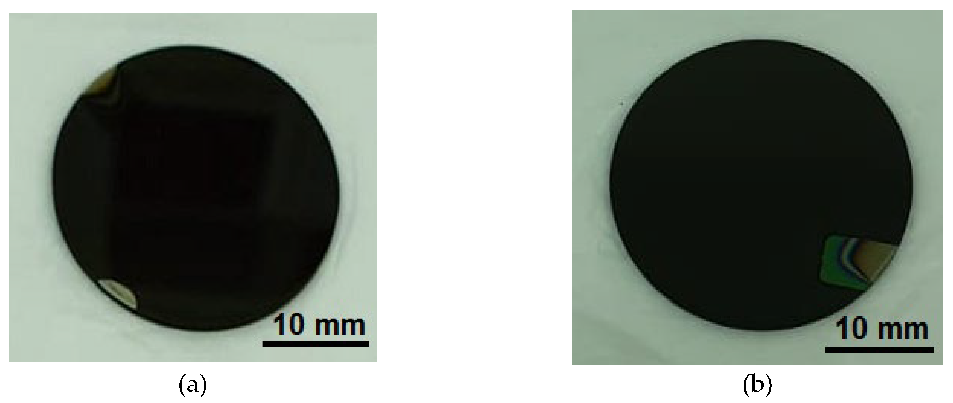
Figure 2.
SEM images (100,000×) of the top surface for (a) TiAlSiN (SL), (b) TiAlSiN/TiN (BL), and (c) TiN thin film coatings.
Figure 2.
SEM images (100,000×) of the top surface for (a) TiAlSiN (SL), (b) TiAlSiN/TiN (BL), and (c) TiN thin film coatings.
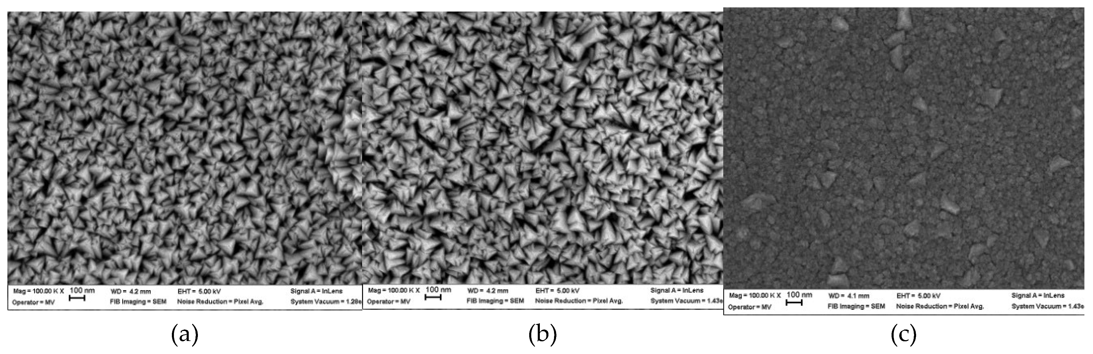
Figure 3.
SEM images (50,000×) of the top surface for (a) SL TT, and (b) BL TT thin film coatings.
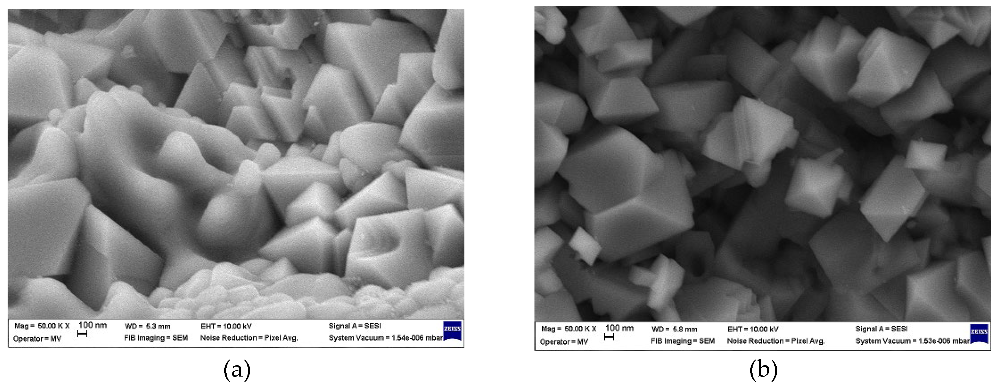
Figure 4.
Load-displacement curves for (a) TiAlSiN-based coatings and (b) C120 steel substrate.
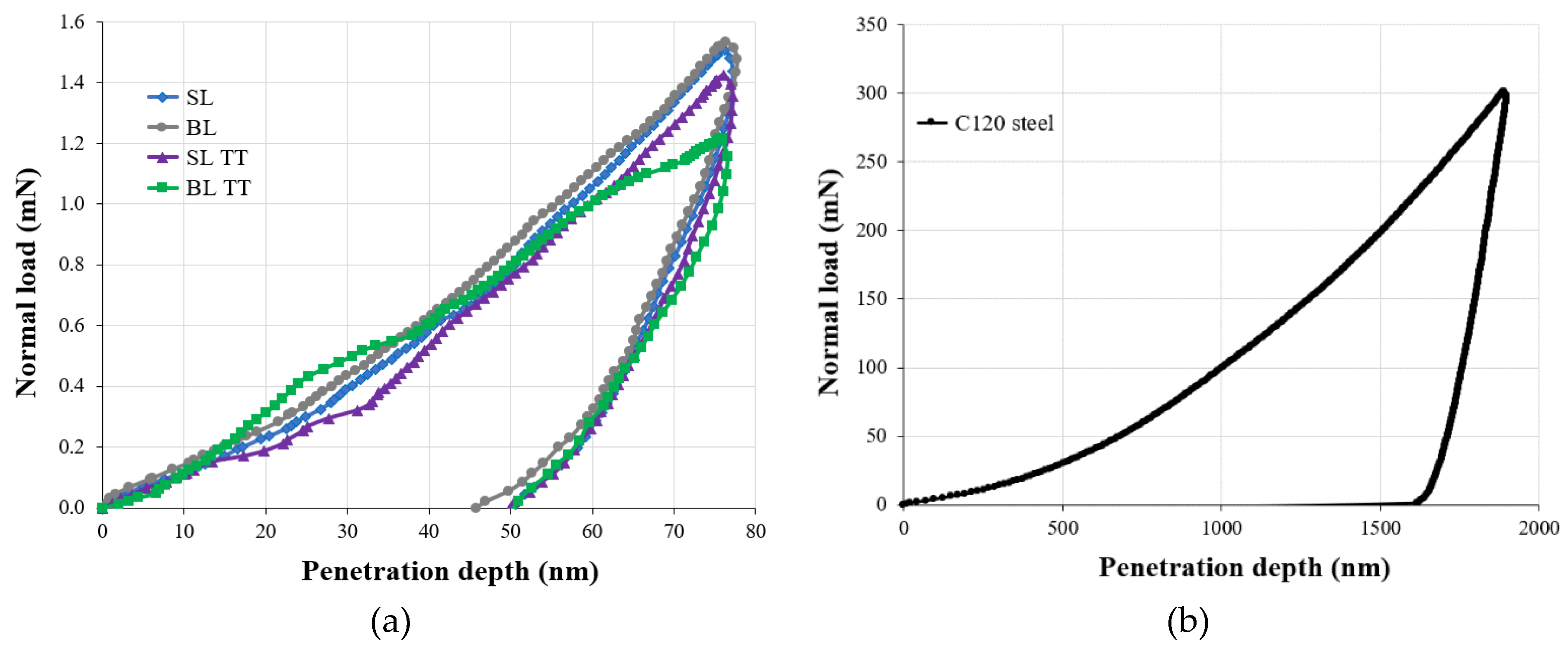
Figure 5.
Variation in (a) penetration depth (Pd) and residual depth (Rd), and (b) elastic recovery (ER) for the TiAlSiN-based coatings tested over a 3 mm scratch length.
Figure 5.
Variation in (a) penetration depth (Pd) and residual depth (Rd), and (b) elastic recovery (ER) for the TiAlSiN-based coatings tested over a 3 mm scratch length.
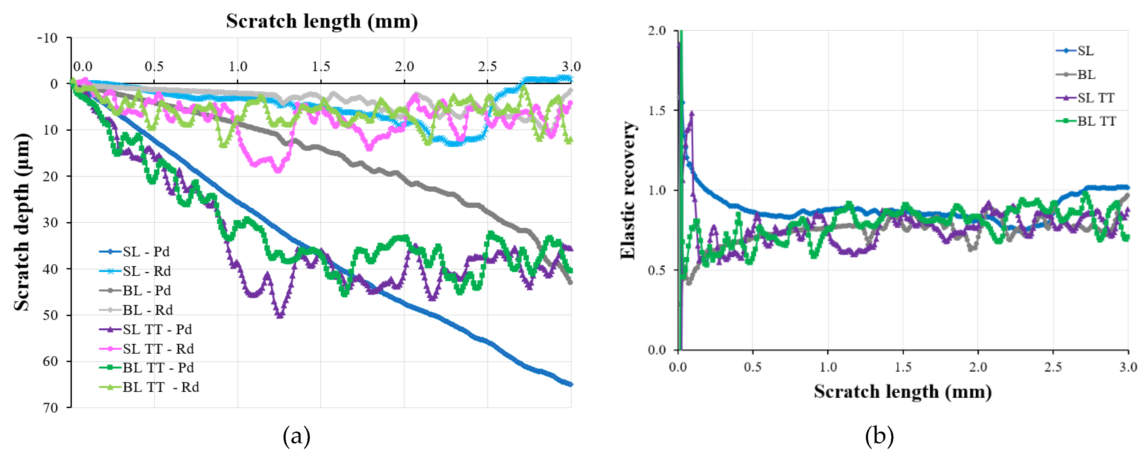
Figure 6.
Variation in (a) acoustic emission, and (b) coefficient of friction for the TiAlSiN-based coatings tested over a 3 mm scratch length.
Figure 6.
Variation in (a) acoustic emission, and (b) coefficient of friction for the TiAlSiN-based coatings tested over a 3 mm scratch length.
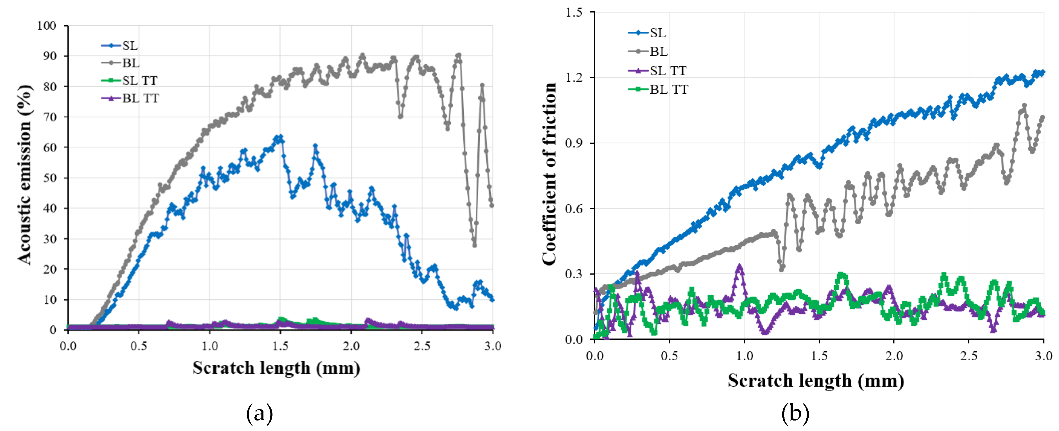
Figure 7.
Optical images (20× magnification) of the scratch tracks left on (a) SL, (b), BL, (c) SL TT, and (d) BL TT coatings tested over a 3 mm scratch length with a linear progressive normal load from 0.03 N to 30 N.
Figure 7.
Optical images (20× magnification) of the scratch tracks left on (a) SL, (b), BL, (c) SL TT, and (d) BL TT coatings tested over a 3 mm scratch length with a linear progressive normal load from 0.03 N to 30 N.
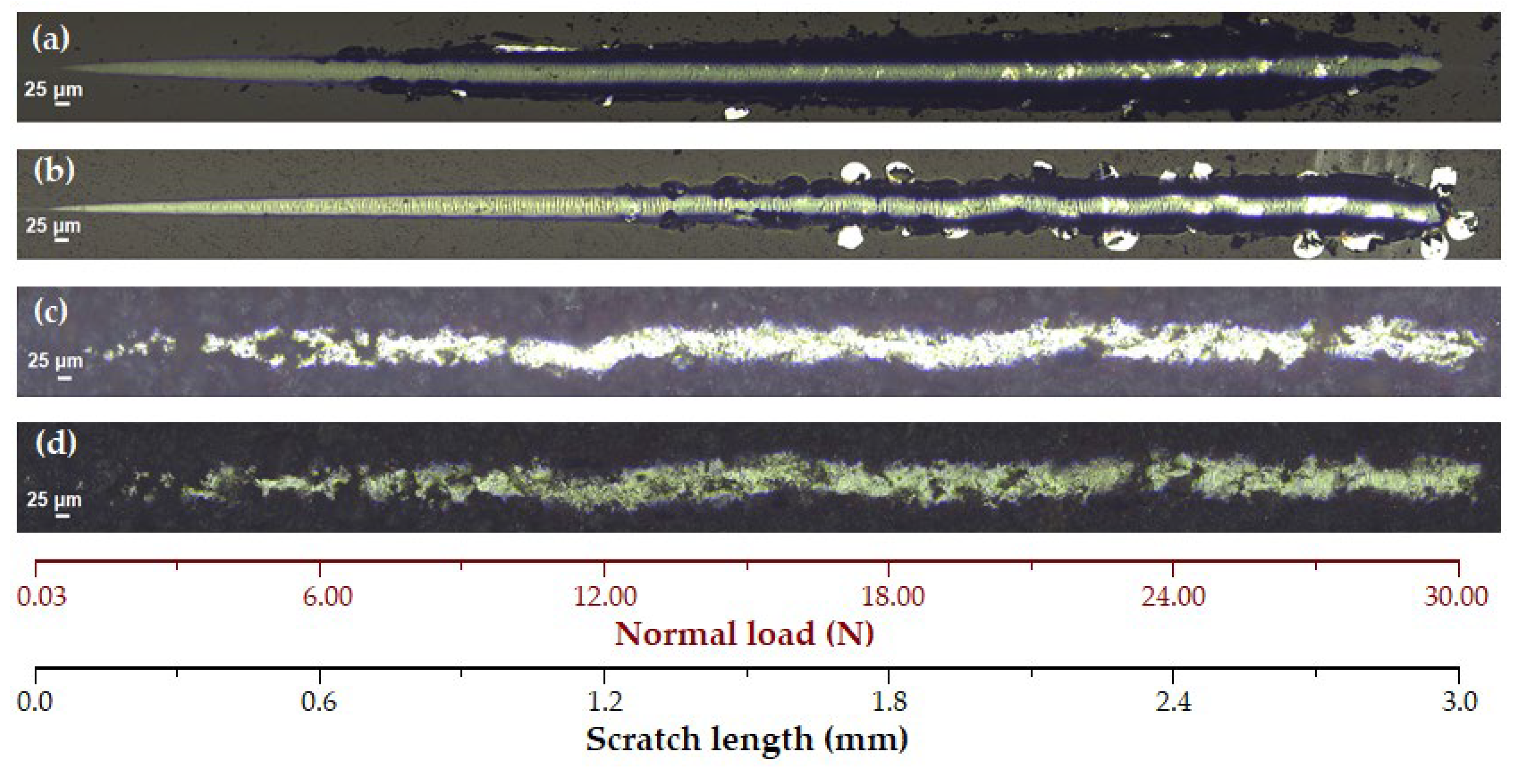
Figure 8.
Optical images (20× magnification) showing the width (ΔY) of the wear track at the end of the 3 mm scratch length for (a) SL, (b), BL, (c) SL TT, and (d) BL TT coatings tested with a linear progressive normal load from 0.03 N to 30 N.
Figure 8.
Optical images (20× magnification) showing the width (ΔY) of the wear track at the end of the 3 mm scratch length for (a) SL, (b), BL, (c) SL TT, and (d) BL TT coatings tested with a linear progressive normal load from 0.03 N to 30 N.
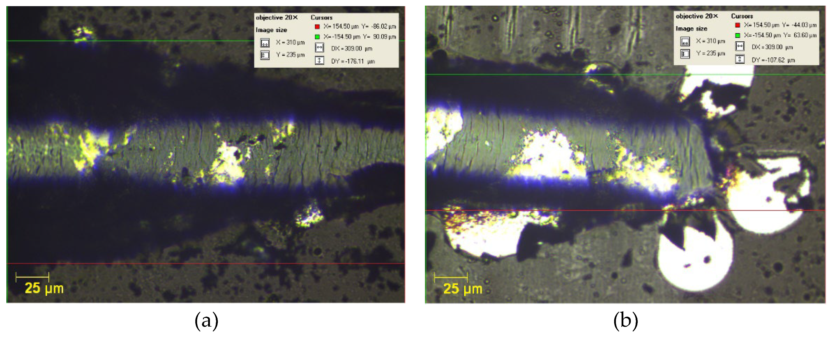
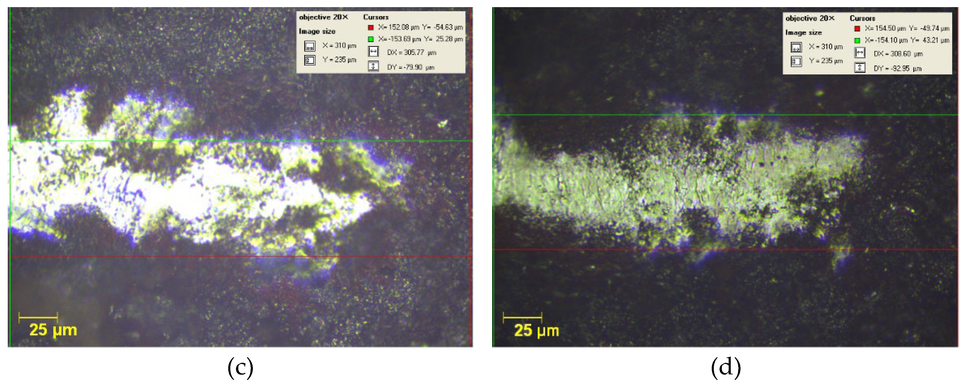
Figure 9.
Evolution of coefficient of friction with sliding distance for the TiAlSiN-based coatings and C120 steel substrate recorded during the tribological tests.
Figure 9.
Evolution of coefficient of friction with sliding distance for the TiAlSiN-based coatings and C120 steel substrate recorded during the tribological tests.
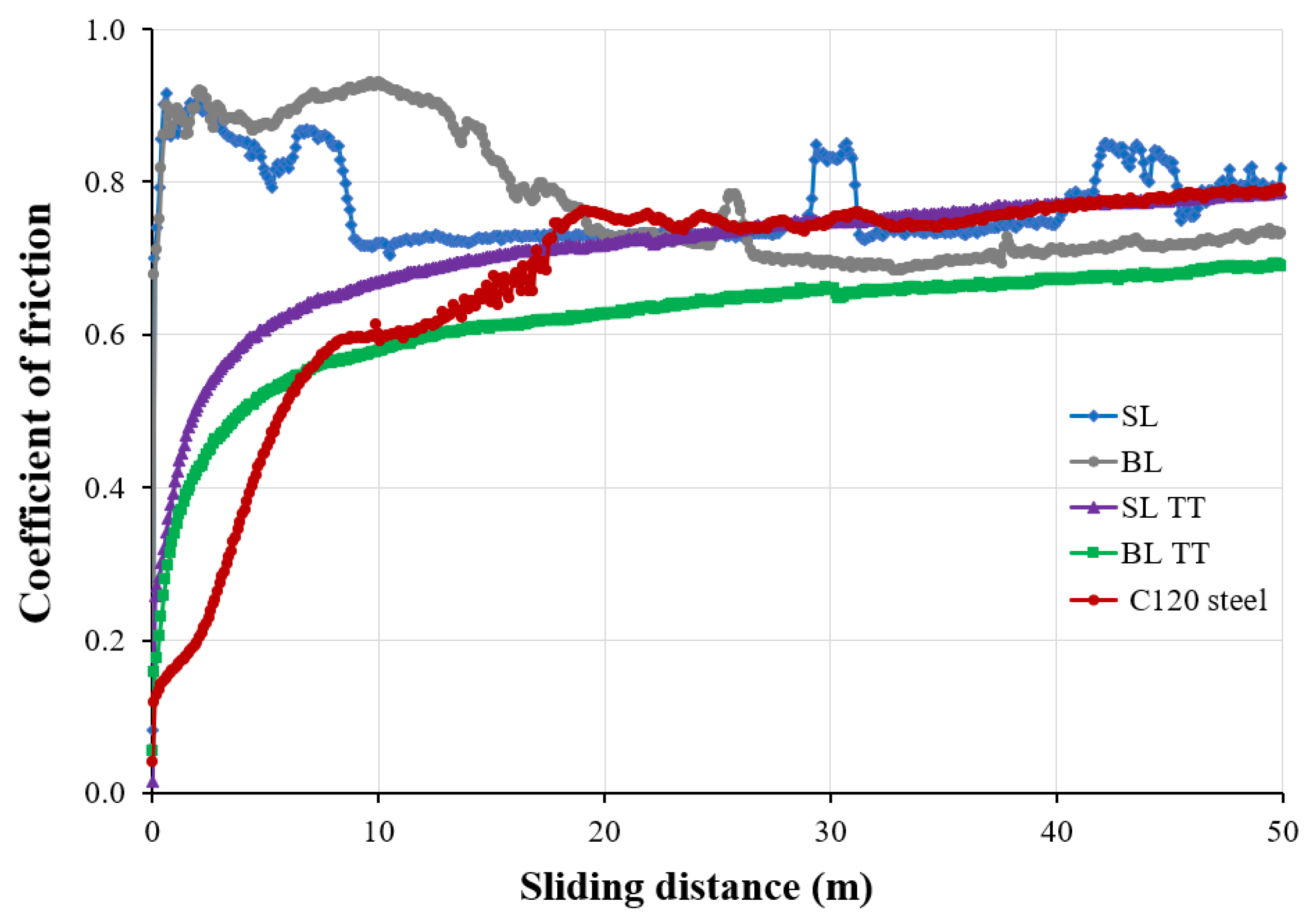
Figure 10.
Open circuit potential (EOC) variation with immersion time in a 3.5 wt.% NaCl solution for the TiAlSiN-based coatings and C120 steel substrate.
Figure 10.
Open circuit potential (EOC) variation with immersion time in a 3.5 wt.% NaCl solution for the TiAlSiN-based coatings and C120 steel substrate.
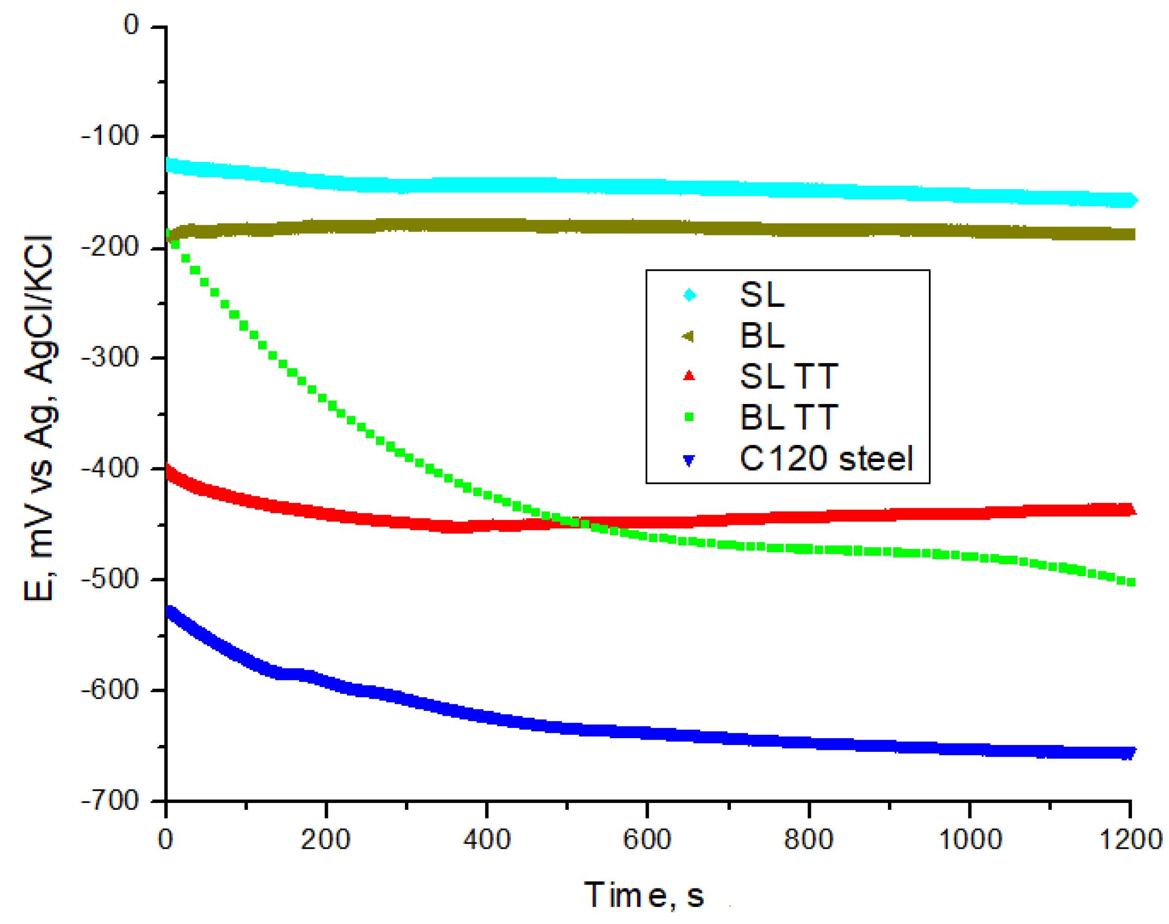
Figure 11.
Nyquist plots of impedance on the Ox/Oy scale: (a) 0 – 30 kΩ·cm2, and (b) 0 – 4 kΩ·cm2 for the samples after 20 minutes of immersion in a 3.5 wt.% NaCl solution.
Figure 11.
Nyquist plots of impedance on the Ox/Oy scale: (a) 0 – 30 kΩ·cm2, and (b) 0 – 4 kΩ·cm2 for the samples after 20 minutes of immersion in a 3.5 wt.% NaCl solution.
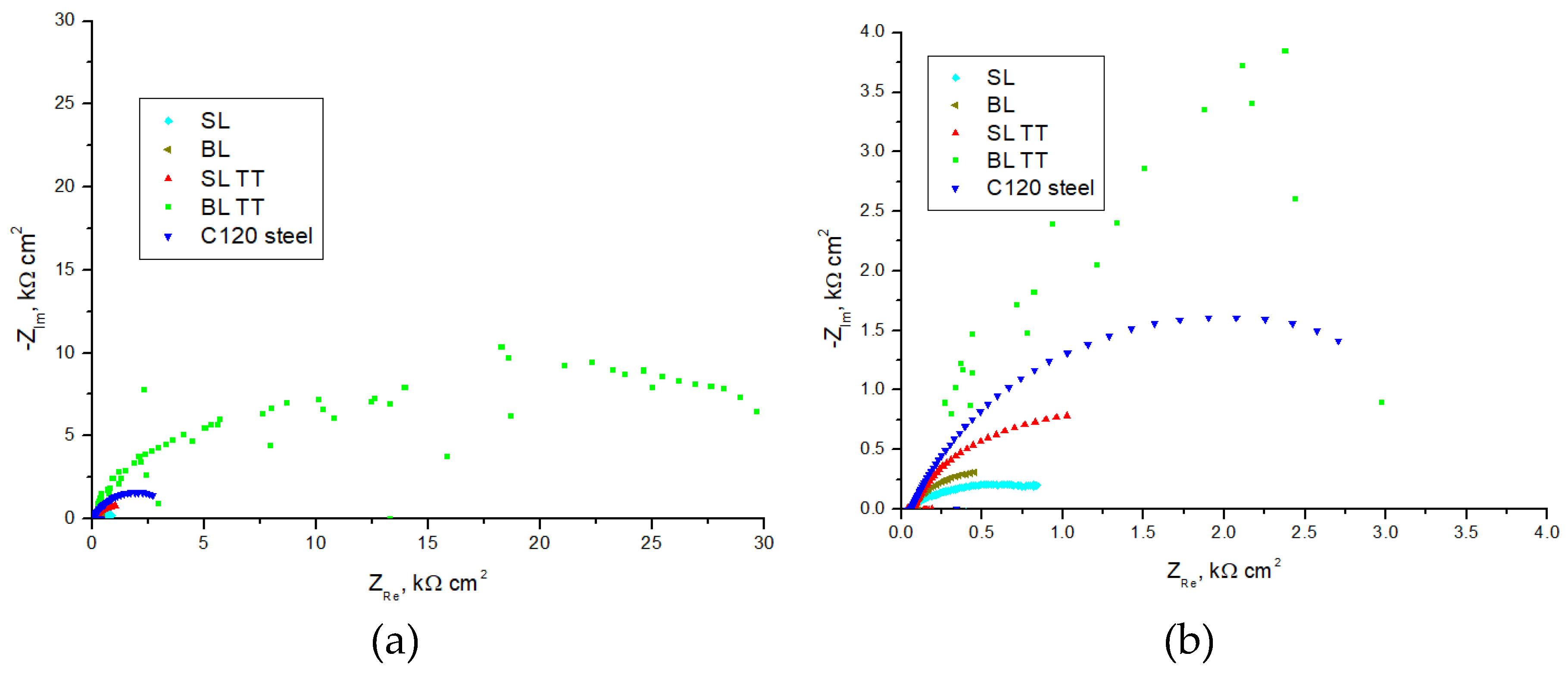
Figure 12.
PDP curves showing the corrosion behavior of the samples in a 3.5 wt.% NaCl solution.
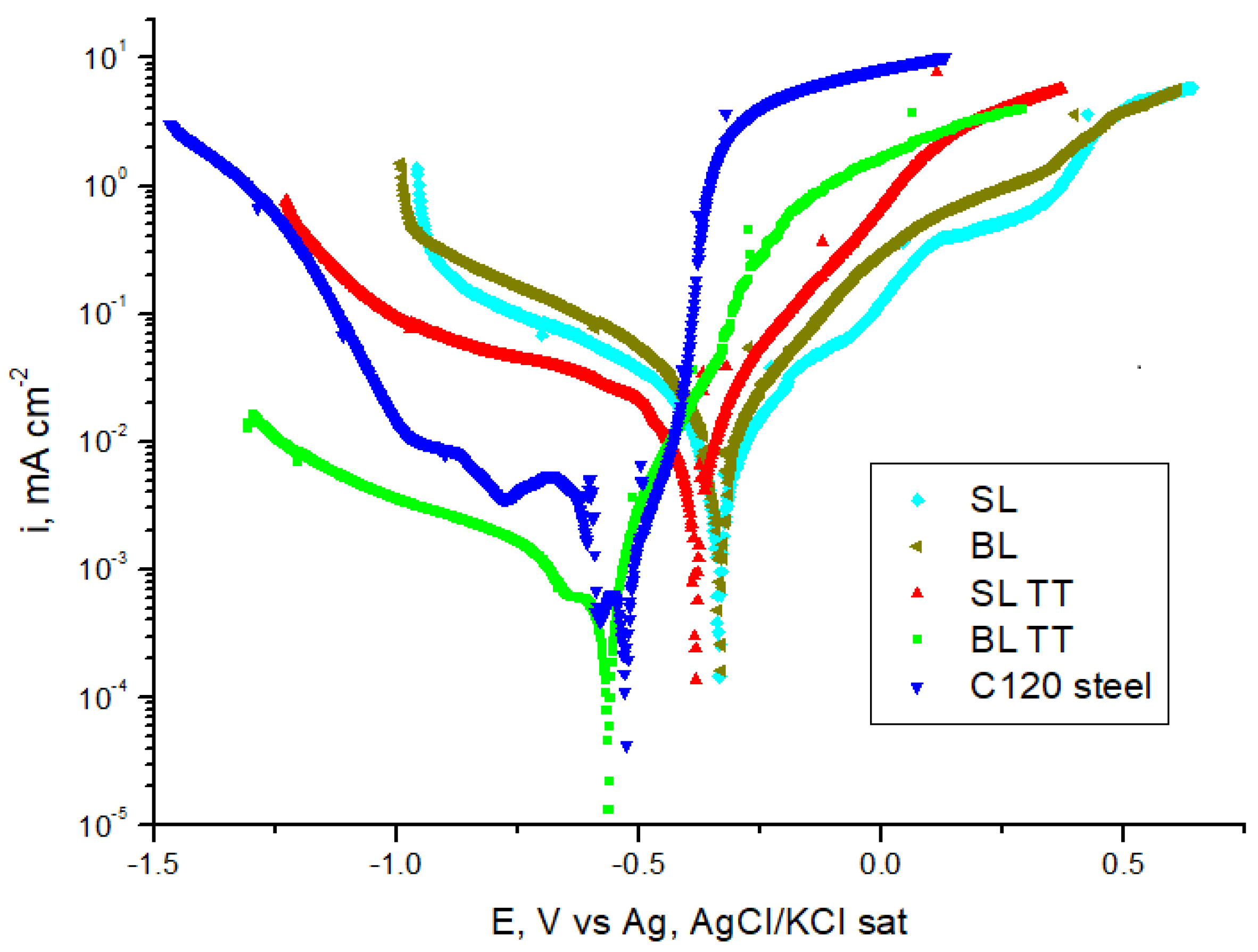

Table 1.
Main technical characteristics of the TiAlSi 75–20–5 (at.%) and Ti sputtering targets obtained using the SPS process [33,34].
| Technical characteristics | TiAlSi 75–20–5 (at.%) target | Ti target |
|---|---|---|
| Diameter × thickness (mm × mm) | 50.8 × 6.3 | 50.8 × 6.3 |
| Density (g/cm3) | 4.093 ± 0.003 | 4.379 ± 0.001 |
| Surface roughness Ra (µm) | ≤ 0.2 | ≤ 0.2 |
| Thermal conductivity at 25 °C (W.m-1.K-1) | 11.93 ± 0.13 | 18.38 ± 0.14 |
| Indentation hardness, HIT (GPa) | 7.88 ± 0.64 | 2.77 ± 0.08 |
| Vickers hardness HV0.02/10 | 730 ± 59 | 256 ± 7 |
| Elastic modulus, EIT (GPa) | 163 ± 6 | 117 ± 6 |
Table 2.
Measurement conditions for determining the mechanical properties of the TiAlSiN-based coatings and C120 steel substrate using nanoindentation and the Oliver & Pharr method.
Table 2.
Measurement conditions for determining the mechanical properties of the TiAlSiN-based coatings and C120 steel substrate using nanoindentation and the Oliver & Pharr method.
| Measurement conditions in instrumented nanoindentation testing |
TiAlSiN-based coatings | C120 steel substrate |
|---|---|---|
| Maximum indentation load (Fmax) (mN) | 2.5 ± 0.1 | 300 ± 1 |
| Loading type | linear | linear |
| Indenter approach speed to the sample (nm/min) | 1000 | 2000 |
| Loading/unloading rate (nm/min) | 500 | 600 |
| Pause at Fmax (s) | 0 | 0 |
| Data acquisition frequency (Hz) | 10 | 10 |
| Poisson’s ratio (ν) | 0.25 | 0.30 |
Table 3.
Elemental content of the TiAlSiN-based coatings determined using EDS analysis.
| Sample | Elemental content ± SD (wt.%) | |||||||
|---|---|---|---|---|---|---|---|---|
| Ti | Al | Si | N | O | Fe | Cr | Mn | |
| SL | 52.4 ± 0.3 | 11.9 ± 0.1 | 3.0 ± 0.1 | 21.2 ± 0.3 | 11.5 ± 0.3 | - | - | - |
| BL | 51.7 ± 0.3 | 12.1 ± 0.1 | 3.6 ± 0.1 | 21.4 ± 0.3 | 11.2 ± 0.3 | - | - | - |
| TiN | 56.6 ± 0.4 | - | - | 5.3 ± 0.2 | 31.1 ± 0.3 | 4.5 ± 0.4 | 2.5 ± 0.2 | - |
| SL TT | 26.7 ± 0.1 | 4.8 ± 0.1 | 0.5 ± 0.1 | - | 27.4 ± 0.1 | 38.0 ± 0.1 | 0.8 ± 0.1 | 1.8 ± 0.1 |
| BL TT | 23.4 ± 0.1 | 7.7 ± 0.1 | 1.1 ± 0.1 | - | 29.7 ± 0.1 | 34.0 ± 0.1 | 0.4 ± 0.1 | 3.7 ± 0.1 |
Table 4.
Mechanical properties of the TiAlSiN-based coatings and C120 steel substrate determined using instrumented nanoindentation and the Oliver & Pharr method.
Table 4.
Mechanical properties of the TiAlSiN-based coatings and C120 steel substrate determined using instrumented nanoindentation and the Oliver & Pharr method.
| Sample | HIT (GPa) |
HV | EIT (GPa) |
E* (GPa) |
HIT/EIT | HIT/E* | HIT3/EIT2 (GPa) |
HIT3/E*2 (GPa) |
Welast (pJ) |
Wplast (pJ) |
ηIT (%) |
|---|---|---|---|---|---|---|---|---|---|---|---|
| SL | 10.29 ± 0.26 |
953 ± 24 |
216 ± 15 |
231 ± 17 |
0.0476 | 0.0445 | 0.0234 | 0.0204 | 12.59 ± 1.17 |
34.62 ± 2.03 |
26.64 ± 0.67 |
| BL | 10.45 ± 0.32 |
968 ± 29 |
215 ± 16 |
229 ± 18 |
0.0486 | 0.0456 | 0.0247 | 0.0218 | 14.25 ± 0.43 |
36.15 ± 1.58 |
28.28 ± 0.27 |
| SL TT | 9.98 ± 0.18 |
925 ± 16 |
188 ± 5 |
201 ± 5 |
0.0531 | 0.0497 | 0.0281 | 0.0246 | 11.74 ± 0.03 |
31.89 ± 1.84 |
26.93 ± 1.08 |
| BL TT | 9.19 ± 0.09 |
851 ± 8 |
139 ± 5 |
148 ± 6 |
0.0661 | 0.0621 | 0.0402 | 0.0354 | 11.12 ± 3.19 |
34.83 ± 1.24 |
24.08 ± 5.93 |
| C120 steel | 4.45 ± 0.09 |
412 ± 8 |
184 ± 2 |
202 ± 2 |
0.0242 | 0.0220 | 0.0026 | 0.0022 | 29335.52 ± 366.46 |
176769.48 ± 8580.53 |
14.25 ± 0.43 |
Table 5.
Critical loads for the TiAlSiN-based coatings deposited on C120 steel substrate.
| Sample | Optical critical loads | Pd critical load (N) | AE critical load (N) | ||
|---|---|---|---|---|---|
| Lc1 (N) | Lc2 (N) | Lc3 (N) | |||
| SL | 2.65 | 6.31 | 14.03 | - | 14.38 |
| BL | 3.28 | 12.26 | 17.28 | - | 20.52 |
| SL TT | 3.89 | 13.63 | - | 12.50 | 15.02 |
| BL TT | 4.72 | 27.82 | - | 16.41 | 21.21 |
Table 6.
Coefficient of friction (µ) and specific wear rate (Ws) for the TiAlSiN-based coatings and C120 steel substrate samples.
Table 6.
Coefficient of friction (µ) and specific wear rate (Ws) for the TiAlSiN-based coatings and C120 steel substrate samples.
| Sample | Coefficient of friction (µ) | Worn track area (µm²) |
Specific wear rate (mm³/N·m) | ||
|---|---|---|---|---|---|
| µminimum | µmaximum | µmean ± SD | |||
| SL | 0.083 | 0.916 | 0.770 ± 0.053 | 946.2–1062.4 | (2.14–2.40) × 10-4 |
| BL | 0.056 | 0.931 | 0.773 ± 0.084 | 866.8–986.7 | (1.96–2.23) × 10-4 |
| SL TT | 0.015 | 0.789 | 0.708 ± 0.088 | 1291.3–1891.9 | (2.92–4.28) × 10-4 |
| BL TT | 0.055 | 0.694 | 0.616 ± 0.083 | 1237.2–1683.1 | (2.80–3.80) × 10-4 |
| C120 steel | 0.041 | 0.822 | 0.670± 0.162 | 1173.8–1646.4 | (2.65–3.72) × 10-4 |
Table 7.
Electrochemical parameters obtained from EIS measurements before the PDP test of the samples in the 3.5 wt.% NaCl solution after 20 minutes of immersion.
Table 7.
Electrochemical parameters obtained from EIS measurements before the PDP test of the samples in the 3.5 wt.% NaCl solution after 20 minutes of immersion.
| Sample | R1 (Ω cm2) |
R2 (Ω cm2) |
Cdl (µF/cm²) |
|---|---|---|---|
| SL | 47.34 | 1057 | 150.4 |
| BL | 66.03 | 854.5 | 1862.0 |
| SL TT | 66.03 | 2184 | 728.7 |
| BL TT | 147.1 | 35550 | 0.159 |
| C120 steel | 68.35 | 4182 | 240.4 |
Table 8.
Electrochemical corrosion parameters derived from the PDP curves for the samples in a 3.5 wt.% NaCl solution.
Table 8.
Electrochemical corrosion parameters derived from the PDP curves for the samples in a 3.5 wt.% NaCl solution.
| Sample | Ecorr (mV vs Ag, AgCl/KCl) |
icorr (µA/cm²) |
Rp (kΩ cm2) |
βa (mV/dec) |
βc (mV/dec) |
CR (µm/year) |
|---|---|---|---|---|---|---|
| SL | -340.9 | 1.1393 | 5.07 | 33.9 | -34.6 | 13.24 |
| BL | -338.9 | 1.2567 | 3.92 | 26.8 | -31.4 | 14.60 |
| SL TT | -384.3 | 1.1658 | 3.06 | 4.2 | -41.5 | 13.55 |
| BL TT | -567.7 | 0.1298 | 46.34 | 25.7 | -45.2 | 1.51 |
| C120 steel | -532.5 | 0.1825 | 28.52 | 22.4 | -36.2 | 2.12 |
Disclaimer/Publisher’s Note: The statements, opinions and data contained in all publications are solely those of the individual author(s) and contributor(s) and not of MDPI and/or the editor(s). MDPI and/or the editor(s) disclaim responsibility for any injury to people or property resulting from any ideas, methods, instructions or products referred to in the content. |
© 2024 by the authors. Licensee MDPI, Basel, Switzerland. This article is an open access article distributed under the terms and conditions of the Creative Commons Attribution (CC BY) license (http://creativecommons.org/licenses/by/4.0/).
Copyright: This open access article is published under a Creative Commons CC BY 4.0 license, which permit the free download, distribution, and reuse, provided that the author and preprint are cited in any reuse.


