Submitted:
19 August 2024
Posted:
20 August 2024
You are already at the latest version
Abstract
It is commonly held that gravitation is a major force field influencing matter. Existing models regard gravitational interaction as a singular weak force; the weakest among the four fundamental forces defined in physics. Recent experimental findings, in both controlled laboratory experiments and natural occurrences, nevertheless, have unveiled the presence of a gravitational repulsion alongside gravitational attraction in the universe. This series of studies reveals that the observed gravitational force results from two immensely powerful distinct forces—gravitational repulsion and attraction—nearly equal and opposing thus in a state of near equilibrium in nature. While the theory of 'Universal Gravitation' established the proportionality of the gravitational force to mass, the recognition of gravitational repulsion force proportional to the temperature as a manifestation of thermal energy has only emerged from present experimental insights. Furthermore, the imbalance between these two forces has been identified as the Newtonian force, initiating the motion of an object. It provides a compelling explanation for the accelerating expansion of the universe: during atomic fusion in stars, a portion of mass is converted into energy. This process increases the energy and decreases the mass of stellar objects. The increase in energy enhances the repulsive force among them, while the reduction in mass diminishes their gravitational attraction, leading to the accelerating expansion of the universe.This paper introduces a model elucidating the characteristics of gravitational forces and the transmission of energy within matter through the concept of 'Gravitational Currents.' A set of postulates is formulated to elucidate the interaction of gravitational fields with matter and the presence of gravitational currents. The discussion is supported by experimental evidence substantiating these concepts.In this series of experiments, a gyroscope - a standard apparatus in the scientific community with a spinning wheel mounted at one end of a freely pivoted rod having full degrees of freedom - is utilized. When the wheel is set in rotation, the rod carrying the wheel precesses[1] around the vertical axis at the pivoted end, while levitating in free space defying the Earth's gravitational attraction. This paper establishes that the conventional explanation involving the cross product of two vectors—the torque due to weight and the angular force (change of angular momentum) of the wheel—fails to account for the observed revolving and lifting forces. Instead, it is demonstrated that these forces result from the upward shear force (which is the lifting force in this case) generated within the axis of the rod and the wheel itself. This phenomenon is attributed to the flow of energy, conceptualized as gravitational current, within the axial rod in the Earth's gravitational field. The described process can be envisioned as a gravitational motor with gravitational current flowing through matter in a gravitational field.The results of the experiments substantiate the conclusion that there exist two fields defined as the intrinsic field and the natural force fields. The intrinsic gravity field is innate (linked) to every object, matter or entity in the universe, and it is dispersed in all directions in free space independent of other entities. The actual force fields manifest between any two objects in the universe once they become cognizant of each other's existence through their intrinsic fields.The inherent force field exhibits a preference/tendency for existence within a medium rather than in free space, akin to the way a magnetic field runs within ferromagnetic materials rather than in open space. If external force fields pass/runs through the medium, it affects the internal force fields of the medium, depending on the magnitudes and the directions of the external force fields and intrinsic force fields. This implies that energy moves through the force field, and under the influence of the gravitational field, this energy flow can be conceptualized as a gravitational current.Gravitational waves and electromagnetic waves share similarities in their roles in transmitting energy through open space. The potential for an analogy within a unified theoretical framework connecting electromagnetic fields and gravitational fields has surfaced, echoing Einstein's attempted unified theory proposed in 1916. The paper delves into the parallels between electromagnetic motors and gravitational motors.Furthermore, alongside the concept of gravitational currents addressed in this paper, the research also elucidated a precise definition of the [Newtonian/mechanical] “force” and mechanism for its origination and function, termed: Intrinsic Energy Spin Force (IESpinF). The analysis presented here demonstrates that the Newtonian/mechanical force arises from a perturbation or imbalance within the equilibrium of gravitational IESpinF, which includes both repulsion and attraction forces. [1] One of the main properties of gyroscopic action is “precession”. Precession is a change in the orientation of the rotational axis of a rotating body. If the axis of rotation of a body is itself rotating about a second axis, that body is said to be precessing about the second axis.
Keywords:
Gravitational Attraction
; Gravitational Repulsion
; Force Field
; Intrinsic Gravity Field
; Gravitational Currents
; Gravitational Wave
; Gravitational Motor
; Energy Propagation through matter
; Gyroscope
; Precession
1. Introduction
Historically, gravitation is one of the most known force fields; nevertheless, relatively little is yet known about it. Much later, electromagnetic forces earned much greater understanding, with extensive practical applications (e.g., electrical machines and communication) for the development of mankind.
The gravitational force, is still considered only as an attraction force, thus our perspectives have been limited to weight, potential energy and so on. It is applied to model behaviors of celestial objects and trajectories of space travel. When confronted with anomalies in the orbit of Mercury, Sir Isaac Newton, diagnosed a limitation of the existing concept of gravitation, in ‘Principia Mathematica’, pp171-182, [1] mentioning the possible existence of an extra force besides gravity, that is obeying the Inverse-Cube Law.
It might appear, that ancient civilizations had a
better knowledge of gravity when we consider gigantic construction work such as
great pyramids [2] in Giza, Egypt, and stone
structures (where each stone weighs around 440 tons) of Inca civilization in
Sacsayhuaman2 and Ollantaytambo3,
Peru.
Careful calculations have also shown that thousands of tons of liquid water (as cloud droplets) floating in midair and cumulating in equilibrium, among each other, could not be explained successfully by presently believed mechanics of convection currents in the upper atmosphere [3]. It is, nevertheless, well analyzed and understood by applying the force of gravitational repulsion (proportional to temperature as a manifestation of thermal energy), together with (Sup. Figure 1) gravitational attraction described in [4] by the author.
Until now, the gravitational field has been considered as a force field. Nevertheless, the relationship among the force field, its energy and energy propagation have not been sufficiently understood in classical physics. Energy propagation in free space macroscopically (e.g., among celestial bodies) and microscopically (e.g., among subatomic particles) have been characterized to-date by means of known mechanism identified as an electromagnetic wave [5]. It is only fair that all these mechanisms (interactions and effects associated with force and matter) should exist everywhere in the universe both microscopically and macroscopically. In classical definitions, currents are interprited as a mechanism for transmitting energy, mostly in association with matter, e.g., electrons in electric current through matter. Waves are considered as the only energy transporting mechanism in the universe where matter is absent. While electromagnetic waves have long been recognized as the primary energy carriers in the universe, gravitational waves have emerged more recently as an additional participant in the propagation of energy throughout the cosmos. Yet, the transmission of energy through gravitational waves [6] has not been fully understood, as the the necessary theoretical frameworks have only been developed relatively recently.
In the concept of the EM field, electromagnetic waves and electromagnetic current are two aspects well-established today. Nevertheless, in the gravitational field, though gravitational waves have been recognized; yet ‘Gravitational Currents’ are not so in any way in our interpretations. The present theory forwarded in the paper, delves into this novel concept of ‘Gravitational Currents’- as a parallel to EM currents.
In the realm of fluid dynamics, a density current, also known as a gravity current, refers to the movement of liquid within a gravitational field propelled by variations in fluid density (sometimes visualized as convection currents). However, it's important to note that this by no means is synonymous with the "Gravitational Current" mentioned in the title of this paper.
The novel concept of gravitational currents could easily be demonstrated using observations made long time ago using the gyroscope. The history of the Gyroscope goes back to many different civilizations4; also, its history, development and utilization is fascinating5. One of the main properties of gyroscopic action is “precession”. Precession is a change in the orientation of the rotational axis of a rotating body. If the axis of rotation of a body is itself rotating about a second axis, that body is said to be precessing about the second axis.
There are two types of precessions: torque-free and torque-induced [7]. The processes that are being analysed here are of the torque-induced model where the precession is the phenomenon in which the axis of a spinning object describes a cone in space when an external torque is applied to it.
When a Spinning Top is spinning on its axis, as shown in Figure 1, it is observed that it does not topple over due to the torque caused by the mass (m) of the Spinning Top and the gravitational pull (g). Instead, it precesses about the vertical axis z. Classical mechanics interprets that the precession is due to the force acting on the center of mass, perpendicular to the plane defined by and [8].
The object is tilted by an angle θ off the z axis when the object is spinning counter clockwise (as viewed from above) at a velocity ω about the OO' prime axis. The precession of the object traces a counter clockwise circle (as viewed from above) centered on the z axis. The cone swept by the precession of the top is indicated by dashed lines.
According to the classical theory, Figure 1 describes how the forces act on a spinning top [8]. Torque is perpendicular to the angular momentum vector . This changes the direction of according to , but not its magnitude. The object precesses around a vertical axis, since is always horizontal and perpendicular to . If the top is not spinning, it acquires angular momentum in the direction of the torque, and it rotates around a horizontal axis, falling over just as we would expect.
According to the classical theory, the precession rate of the top (In Figure 1) has been calculated as follows. The magnitude of :
Thus,
The angle the top precesses through in time dt is dφ:
The precession angular velocity,
and from this equation we see that:
or, since
In this derivation, we assumed that ωP≪ω, i.e., the precession angular velocity is much less than the angular velocity of the Spinning Top. The precession angular momentum along the z-axis, caused by angular velocity ωP, is hence small. This is seen in a slight bob up and down as the gyroscope precesses, referred to as nutation [9].
All the explanations provided above stem from observations rooted in gyroscopic action.
Upon scrutinizing classical explanations of gyroscopic actions, and considering additional experimental observations outlined in this paper, it becomes evident that these classical explanations are at odds with established laws of classical mechanics in physics. The aim of this paper is to refine these explanations, potentially paving the way for a deeper comprehension of the universe and its mechanisms.
In this regard, what is being examined here, is how fundamental forces simply work in the gyroscopic action utilizing the forces of gravitational attraction and gravitational repulsion. This would give a complete view of how the gyroscope works elucidating how gravitational currents work in nature.
The concept of gravitational currents (in relation to gravitational wave) is demonstrated in this paper by an experiment conducted using an apparatus consisting of a rod which is pivoted at one end such that it had all degrees of freedoms of movement. At the other end of the rod a spinning wheel is mounted. The observations are qualitatively compared with the electrical current flowing in a magnetic field. It is hoped that any observed similarity between electromagnetic fields and gravitational fields, could lead to possible analogies (single theoretical framework) between electromagnetic fields and gravitational fields; could possibly lead to the unified theory proposed by Einstein in 1916
2. Method
The apparatus, as shown in Figure 2, consists of a wheel W of mass m (randomly chosen from a general-purpose riding bicycle). It has weight of 2.8 kg when inflated to 275 kPa, diameter 720 mm and width of the tire 38 mm. The W is mounted to the end of a solid cylindrical aluminum rod, denoted as R, which has a length L and a diameter of 15.8 mm. The length L varies based on the experiments conducted as described below. The mounting is such that W would freely rotate around an axis through the center of R. R is mounted at P such that it can either be firmly bolted to the vertical shaft S thus making it a rigid mounting, or be allowed to pivot at P such that R could freely move up and down in the vertical plane. S is vertically mounted to a bearing at the base B, equipped with a digital scale that measures the weight of the entire apparatus. This setup allows S to freely rotate around its vertical axis for all experiments detailed in this paper. Two strain gauges X and Y are mounted on R as shown in Figure 2, in a manner that their position between P and W could be varied to perform the experiment under different configurations. A resting pad is affixed as illustrated to restrict the vertical movement of the rod at its lower end.
Exp. 1 to 6 were performed as described below.
Seven (07) different experiments are performed in this research as described below.
The simplified diagrams of Exps. 1-3 are given in Figure 3(a) – (c).
Exp. 1:
R was horizontally bolted at P to the vertical shaft S as shown in Figure 3(a), thus making it a rigid mounting, having no freedom to move in the vertical plane. R is free to rotate around the vertical axis of S. W is at rest (not rotated). Readings of X and Y are recorded.
Exp. 2:
Experimental setup was arranged identical to that of Exp. 1. W is set to rotate around 20 rad/s. Although R is free to rotate around the vertical axis of S, no movement is observed. The position of R-W was moved manually around S to observe the behavior of the R-W. Readings of X and Y were recorded. See video V3 for more information: Gyroscopic action with a fixed and a pivoted axis https://youtu.be/8FBTIsVrnd4
Exp. 3:
Exp. 2 is repeated with the same setup except that, at P, R is pivoted (Exp. 2 setup is modified by unbolting R from P) such that it could freely move up and down in the vertical plane. The wheel is set to rotate around 20 rad/s. Though R is pivoted at P and free to fall down, it does not. Interestingly, it levitates to remain in whatever orientation it was placed in, in the vertical plane (see Figure 3(c)) and both R-W start to turn around the vertical axis S (the direction depends on the rotation of the wheel). If W turns anticlockwise (as viewed from outside), R revolve around S in the anticlockwise direction (as viewed from above) at a speed around 2 rad/s; vice versa if W rotates clockwise.
Initially, R was placed close to the horizontal, then at different angles ~ ± 75° to the horizontal. The pattern of the results obtained for different orientations were proportionately similar. Therefore, for the convenience of taking measurements, R was placed at the horizontal position, when readings were recorded in the rest of the experiments performed in this study.
Exp. 3.1
Extension of Experiment 3: This version of the Exp. 3 involves placing the end of R on the top of S freely (without utilizing any mechanical joints) as demonstrated in Supplementary Video 1 (Gyro action of bicycle wheel without mechanical joint at S). The corresponding video V1 for this version of the experiment is provided as supplementary data Video 1 (V1: Rotational motion of a bicycle wheel due to its gyroscope effect https://youtu.be/a3QIS5Z99Pk).
Exp. 4:
Repeated the Exp. 3 by changing the position (L1/L2) of the strain gauges along the rod R. The results are given in Table 2 and graphically represented in Figure 5.
Exp. 5:
rpm of R-W around P was measured for two different lengths of L, 20 and 44 cm, starting at L = 44 cm and the angular speed of the rotating wheel W was maintained around 8 rad/s. The distance L was then changed to 20 cm while rotating the wheel W as in the previous instance. The distance L was then continually changed between 20 and 44 cm several times back and forth while W is still being rotated. See supplementary video V4: Measurements of angular velocity in gyroscopic precession https://youtu.be/1bLt3LuIAHA
Once the wheel is set to rotate at 8 rad/s, the speed of the wheel keeps on dropping gradually due to air and axial bearing resistance. This natural reduction of speed of the wheel when initially set to rotate at 8 rad/s, was measured in experimental setup of Exp. 2 in which R-W was kept stationary by bolting at P. The stationary measurement was taken in order to observe whether there is any change to retardation of W due to the change of L as described above.
Rotational speed of R-W around shaft S with respect to the length L is also measured, i.e., time for one rotation of R-W around P was measured for lengths of the rod of 28.0, 34.5, 40.5 and 48 cm. The results are given in supplementary data (Sup. Figure 2).
Exp. 6.
A laser displacement sensor was added after analyzing the data of Exp. 1 to 3. Therein, the laser displacement sensor is rigidly fixed to S as shown, in order to measure the vertical movement of R with respect to the fixed reference point. The distance value d is acquired wirelessly using Bluetooth (BT) signal. The relevant video is shown in supplementary video V5: Vertical oscillation of a gyroscope during precession https://youtu.be/jGYUkeryvqM
Exp. 7
R is pivoted at P, such that it could freely move up and down in the vertical plane as in Exp. 3. Instead of manual rotation ofW, a motorized W (560 g, 265 mm in diameter, 60 mm width) with a radio control (RC) motor was used to control its angular velocity. The battery and the control system are attached to R as shown in Figure 4, without external attachment/connection to R-W.
The inertia of the wheel has to be large enough to amply demonstrate the gyroscopic action and hence either the weight or the diameter of the wheel has to be increased. In this case, increasing the weight was chosen. To demonstrate the precession at a sufficient speed, a brushless, low torque ‘drone-motor’ was used in this experiment. Hence the R-W has to supported by a counter weight at the other end of R as shown in the Sup. Video V6. This counter weight enhances the precessing at W-R at a lesser force. W reached an angular velocity of around 1350 rpm. See supplementary video V6: The behavior of a motorized rotating gyroscope wheel https://youtu.be/xessa-_McxM
3. Results
Exp. 1 - 3:
Strain gauges X and Y reading for Exps. 1 – 3 are given in the Table 1. Exps 1 and 2 produced the same character (+/-) readings but they were flipped (reversed) in Exp. 3 (Figure 2(c)). At X, tension in Exps. 1 and 2 become compression in Exp. 3 and at Y, compression in Exps. 1 and 2 become tension in Exp. 3.
Supplementary Video 2
describes Exp 1 and Exp 3
V2: Alteration of strain distribution along the axis of a gyroscope during precession https://youtu.be/QnxEXq40oUI
Supplementary Video 3
describes Exp 2
V3: Gyroscopic action with a fixed and a pivoted axel
Exp. 4:
Values of strain gauge readings with respect to their position along the rod R are tabulated in Table 2 and plotted in Figure 5.
The graphs in Figure 5 would be expected to be straight lines. The mass of the rods sections and the two strain gauges X and Y are around 500 g, compared with the mass 2.8 kg of the wheel W. Furthermore, the joints at X and Y are not as rigid as an uninterrupted or an ideal rod. These reasons could explain the shapes of the graphs. The patterns of the results obtained, nevertheless, proportionately indicates a similar force distribution within the rod for all situations (orientations of the rod in vertical plane) considered.
Exp. 5:
The angular velocity of W reduces due to the frictional forces, such as air resistance, with time. However, the angular velocity pattern of W remains unaffected by the length of R, regardless of whether R-W is fixed or rotating at any angular velocity. However, the angular velocity of R-W reduces with reduction of the length L, of R. Note that, this angular velocity increases again with the increase of L. Further study (see supplementary data Sup. Figure 2) shows that the angular velocity of R-W linearly increases with increase of L.
Supplementary Video 4
V4: Measurements of angular velocity in gyroscopic precession https://youtu.be/1bLt3LuIAHA
Exp. 6:
The distance d (the vertical motion of the rod) is plotted against the time from the start to the end where the rod stops on the rest pad (see Figure 7).
Supplementary Video 5
V5: Vertical oscillation of a gyroscope during precession https://youtu.be/jGYUkeryvqM
Exp. 7:
the nearly constant angular velocity of W keeps the rotating plane of R-W unchanged (close to constant). There is no change of angular momentum in the direction of vertical plane, due to the torque caused by the weight of W (towards the earth in vertical plane).
It also shows (Video 6) that the increase of speed of W raises it upward. Tension and the compression also increase proportionately. (or in other words, increase of speed of the wheel, increases the tension and the compression of the rod, resulting an upward motion or raise of the R-W as in video 6). The revolution of R-W about S is nearly 3.33 rounds/min.
*** The total weight of the experimental setups, measured on scale B, remained constant throughout each and every experiment conducted.
Supplementary Video 6
V6: The behavior of a motorized rotating gyroscope wheel https://youtu.be/xessa-_McxM
4. Discussion and Analysis
4.1. Summery of Observations
- i)
- ii)
- Exp. 2, Figure 3(b) ⇨ R is still rigidly bolted at P, but W is rotated. Even though W is rotated, the setup still produces tension (T) at X and compression (C) at Y similar to the observation made at Exp. 1. R remains still. Even if the R-W is rotated manually around S, (which causes change of angular momentum due to change of the direction vector; i.e. change of angular force) it stays in the position where it was manually placed. Classically, this situation fulfills the requirement for a cross product, initiating third force perpendicular to angular force and the force due to the weight, towards the direction tangent/perpendicular to the R-W and mg. This third force is the force needed for rotation of R and W. However, this does not happen violating the law of cross product,. See Figure 3(b) and Table 1. (Supplementary Video 3, https://youtu.be/8FBTIsVrnd4)
- iii)
-
Exp. 3, Figure 3(c) ⇨ when R is unbolted (pivoted or just placed on top of S as shown in Sup. Video. V1) at P, following four effects (1), (2), (3) and (4) are observed. These are simultaneous and mutually interdependent events. When W is rotating:
- (1)
- R-W levitates/elevates/lifts in space.
- (2)
- R-W revolves around the axis S.
- (3)
-
Strain gauge readings flip, indicated in (Table 1):
- a)
- compression (C) at X (upper strain gauge) [from formerly tension to now compression] and
- b)
- tension (T) at Y (lower strain gauge) [from formerly compression to now tension].
- (4)
- Vertical sinusoidal oscillation (nutation) in R is detected by the Laser Displacement Sensor (Figure 2) as shown in Figure 7.
- iv)
- The distribution of tension and the compression along the R at Exp. 1 and 2 has also been reversed (Figure 5).
- v)
- Angular velocity of R-W around the vertical axis S has been increased with the increase of length L (and decreases with the decrease of length L). See Figure 6.
- vi)
-
Speed of the W was controlled remotely,
- a)
- The constant angular speed of W, keeps the rotational plane of W-R constant around S.
- b)
-
Increase of angular speed (Angular acceleration) of W raises R-W in upward direction.Nevertheless, the rotational plane of R-W did not surpass the horizontal plane when initiated from the initial lower starting position, as demonstrated in Supplementary Video 6.
4.2. Analyzing Results from the Classical Mechanics Perspective; Reveals Inconsistencies
In Exp. 1 and Exp. 2 above (Figure 3(a) and (b) respectively), observations and measurements are consistent with classical mechanics. The weight mg of W causes equal and opposite reaction at P (which is eccentric):
- i)
- The constant angular speed of W, keeps the rotational plane of W-R constant around S.
- ii)
-
Their eccentricity causes:
- a.
- constant shear force throughout the rod,
- b.
- c.
In Exp. 3 (Figure 3(c)), the couple-of-forces TL2 and CL2 (Table 1 and Figure 3(c)) does not act in the direction that would hold W afloat. Instead, the forces acting on R, including TL2, CL2, mg and the reaction at P, collectively exert a tendency for R-W to sway and fall around P, towards Earth under the gravity.
Exp. 3 observations (1), (2) and (3) in Sec. 4.1 (iii), nevertheless, indicate situations contradicting classical mechanics.
- 1.
- 2.
-
Flipping (reversal) of forces tension to compression and vice versa, of strain gauges X and Y, was observed in Exp. 3 and 4. Such force changes due to angular velocity cannot be explained from the existing knowledge of classical mechanics.
- a.
-
The reversal of tension and compression forces along the rod R should, nevertheless, offer insights into maintaining the R-W arrangement afloat (levitating). For the rotation of R-W without toppling, three factors must align simultaneously.
- i.
- W must rotate
- ii.
- W-R should be free to rotate about S axis,
- iii.
- W-R should be free to move in the vertical plane
If any of the above i, ii, iii is absent, the floating of R-W ceases. These three factors mentioned above are mutually interdependent and simultaneous to enable the floating of R-W. The reversal of forces occurs within the rod due these three simultaneous-mutually interdependent actions.
- 3.
- Preventing vertical movement (oscillation observed in Exp. 6) by rigidly bolting R at P (Exp. 2), inhibits rotation of R-W. Eq. 6, delineating precession (ωP) in classical mechanics, lacks a term accounting for the observed oscillation (nutation), which is essential for describing precession accurately.
- 4.
- The observations in Exp. 5 reveals a violation of the well-known theory of conservation of angular momentum. It was observed that the angular velocity increases with the length of R (Rotation time is short) and vice versa (Angular velocity is low when the length of R is decreased). Hence the concept of angular momentum conservation is challenged.
- 5.
- Observations (4) in Exp. 6; vertical sinusoidal oscillation of R can be referred to as nutation [10] in gyroscope precession. If nutation is restricted/inhibited by rigidly bolting R at P (Exp. 2), then the precession ceases. Such a phenomenon incorporating the precession and nutation is not explained in classical mechanics.
- 6.
- When W starts to rotate, R-W automatically lifts-up and begin revolving around its pivoted vertical pole (Video V6). The upward/lifting force acting on R-W due to the rotation of W is not explained in classical mechanics. When angular velocity of W is constant (exp. 7), there is no apparent downward movement of W, (inhibiting the force downward – due to mg). Angular momentum along L due to the rotation of W and downward force due to mg are two independent events. Therefore, mg should move downward but no such movement is observed. Third force may occur due to the cross product, however, the independent forces should act by their own. In Exp. 2, this cross product does not occur even though the said two forces, L and τ are presented.
- 7.
- Increase of angular speed of W raises the R-W in upward direction (Exp.7). This observation is not explained in classical mechanics. Upward movement of W should reverse the torque τ and reverse the direction of precession according to classical definition. Yet, this was not observed in the Exp. 7.
Raising of R-W can only be achieved by reversing the forces of tension and compression along R-W as we have seen in Exp. 3. (as shown in the Figure 3(c)). This same observation of reversal of forces was observed in Exp. 7 as well.
Even though classical mechanics does not present any correlation between L and the strain forces (tension and compression) that take place along R-W due to the rotation of W, it has been observed in this series of experiments that there exists a strong relation between L and strain forces.
4.2.1. Observations that Do Not Align with Newton’s Third Law
Mass of the R is considered as negligible. The scale at the base of S (see Figure 2) indicates the force F due to R-W on S. F is the reading of the scale and this is equal to mg.
According to the Newton’s 3rd law, (refer Figure 8) for the stability of the rod R-W, a counter force F on S (a force E which is equal to F in magnitude and opposite in direction) must act on R-W by S. According to the observation (and the diagram above) R-W stays on top of S as indicated above in Figure 8 with only the external force E (See Supplementary Video 6 also).
i.e:
For the stability of R-W, forces in R-W must be equal and opposite.
F (vertical force at S due to R-W (indicate at scale)) + weight of the wheel (mg) = upward reaction force E
mg + mg = E, according to the Newton’s 3rd law E = mg
This is not accepted. Hence, the Newton’s 3rd law fails at this instance.
See Supplementary Video 7 V7: Forces exerted on a bicycle wheel during gyroscopic action https://youtu.be/jCsnfgD4OY8
4.2.2. More confusions in Classical Mechanics
- 1.
- It's noteworthy to point out that in the conventional explanation, the torque τ is depicted at C (Figure 1), the center of mass of the "top." However, in classical mechanics, it should act on the pivotal point, O, of the "top," causing confusion and a loss of clarity within the classical explanation's definition.
- 2.
- Further, referring to the Sup. Figure 3, a strong spring was introduced to L, between P and the strain gauge as shown in Sup. Figure 3(a). The forces registered and observed in strain gauges (Sup. Figure 3(c)) and the spring clearly make a confusion with existing/accepted theories and knowledge in physics.
When a tension or compression is observed in a particular region of a spring, it should remain the same along its length, but what was observed is a tension force in part with a compression force in the adjacent part (Sup. Figure 3(c)) which is not compatible with classical mechanics.
See Video 8.
Supplementary Video 8
V8: Strain distribution along the spring-integrated rod within the gyroscope https://youtu.be/xmQ3Zg88ks4
4.3. Conclusion from the Experimental Observations
- 1.
- The pattern of reversal of tension and compression forces due to rotation of W, with the rod are not answered by classical mechanics.
It has been shown in this paper, that the revolving and lifting forces are not explained by the conventionally accepted theory of cross product of two vectors, the torque, τ due to the mg and the angular force (change of angular momentum, dL/dt) of the wheel, but by the lifting force (upward shear force) created in the axis of the R-W itself. The reversal of forces occurs within the rod due to these three simultaneous mutually interdependent actions discussed in Sec. 4.2.2.
- 2.
-
Angular momentum is not conserved
- (ii)
- When W rotates with a certain angular velocity, the angular velocity of W decays with time due to friction caused by surrounding air, axial bearing etc. The pattern of the reduction of angular velocity of W is not affected by the self-propelled precession of R-W (whether it is stationary or precessed about the pivoted axis of S, Exp 5 and Video 4). As a result of precession, R-W acquires angular velocity/angular momentum, but the origin of this momentum remains unidentified.
- (iii)
- Angular momentum of R-W rotating about axis S is self-generated (not well explained in classical mechanics) and it shows contradictory behavior against the law of conservation of angular momentum. The angular momentum of R-W decreases when L become short and increases when L become longer which is also a contradictory behavior in the perspective of classical mechanical law of conversation of angular momentum of a system. See Figure 6. Furthermore, it is noteworthy that the change of the length of L does not affect the angular momentum of W rotating about axis R.
4.4. A New Knowledge Is Needed to Understand Above Observations
The discussions and analysis regarding the aforementioned observations in this experiment open the door to a new perspective in understanding the interaction of energy with matter in the universe.
Observing natural phenomena makes it evident that energy propagates through free space and matter in the universe. Two primary modes of energy propagation are waves and currents, such as electromagnetic waves and electromagnetic currents (referred to as 'wave' and 'current').
A universally acknowledged principle states that concentrated energy at a point/area disperses outward over time (For example, Black Body Radiation, Stefan’s Law). Given this understanding, the energy of the rotating wheel W is also dispersed as frictional forces (Frictional forces later produce thermal energy, sound energy etc.). According to classical mechanics, energy of W is gradually reduced by frictional forces and not by any other alternative mechanism.
In these experiments, we observed that when energy is applied to W within a field (Here it is, Earth's gravitational field), W not only undergoes rotation but also alters its behavior in free space along with the other components in the W-centered system. Essentially, the system comprises Earth, R, and W. R functions as an interface within the gravitational attraction and repulsion fields connecting Earth and W. Components S and B (Figure 2) rigidly mount to the earth, can be considered as a part of earth itself. As a result, R is influenced by the mentioned fields between Earth and W, as it acts as a mediator facilitating interaction between them. The only possible interaction between W and earth should relate to energy, transferred through R.
In this situation, the energy from W disperses by propagating through space, involving both free space and matter. The phenomenon of energy flowing through matter is a commonly observed occurrence in nature. In this experiment, as discussed in the above paragraph, energy of W may also disperse/dissipate to earth via R. it's observed that this energy flow can alter the properties of matter (in R), contributing to the establishment of a link between W (the energy source) and Earth (the energy receiver).
In this experimental scenario, if energy flows through matter, it could be attributed to a current. As this is occurring within the gravitational field, the current can be defined as “gravitational current”. This gravitational current, occurring under a gravitational field, bears similarities to the flow of electromagnetic current under an electromagnetic field. In simpler terms, this process can be seen as a gravitational motor—a gravitational current coursing through matter/rod in a gravitational field, akin to the electromagnetic motor where an electric current flows through matter/conductor in an electromagnetic field.
Since classical physics fails to provide satisfactory explanations for the observation of the above series of experiments, it becomes imperative to explore alternative mechanisms to elucidate these phenomena more clearly.
5. Proposed Alternative Theory
“Despite the scale of size, any system is associated with spin, which could be considered analogues to the matter wave or the de Broglie wavelength [58]. Any system irrespective of the size can produce energy fields in free space. Owing to this assigned nature, an alternative view is to describe the phenomenon as an intrinsic spin energy (of a system) and intrinsic spin energy field (in a field).” [11]
Recent evidence supporting the presence of both gravitational attraction and repulsion fields [3,9,10,11] offers a promising solution to this problem. The following hypothesis, grounded in a set of postulates and assumptions, aims to provide a satisfactory explanation. The mechanics of this phenomenon become more understandable by considering the following assumptions, especially under the established concept [4] confirming the existence of gravitational repulsion (antigravity) fields and forces among matter/objects (refer to Supplementary Figure 1).
The presence of a solitary entity in space holds no inherent significance. This entity possesses intrinsic characteristics, including matter, energy, and other yet-to-be-identified properties [11]. The information pertaining to these intrinsic properties is encoded within the entity through a physical quantity defined here onwards as the intrinsic spin (Ispin). (The spin is an important intrinsic property of elementary particles and plays a fundamental role in the interactions among them. All fundamental interactions are spin dependent. In electric and magnetic interactions, similar to positive and negative charges or north and south magnetic poles, it is defined as, parallel spins repel each other and anti-parallel spins attract each other [12]. In contrast, in gravitation, it is defined as, a pair of particles with parallel spins are attracted to each other [13,14,15,16]. Author has published a paper [11], defining that the electromagnetic wave, electric current and their effects are comfortably explained by assuming a natural spin, called Intrinsic Spin [11] (ISpin)).
It is also defined that the intrinsic field (or information field), formed instantly by the entity's intrinsic spin, permeates throughout the universe, encompassing all intrinsic information specific to that entity. Importantly, this intrinsic field remains independent of the presence of similar entities elsewhere in the universe6
When another entity emerges within the vast expanse of the universe, their intrinsic fields intersect. This overlap facilitates a mutual recognition of each other's existence in space through their respective intrinsic fields. The intrinsic fields of the entities establish a shared understanding of their coexistence in the universe, along with the intrinsic properties encoded within these fields. Once this mutual acknowledgment occurs, unique force fields (Inherent force field which is also represented by intrinsic energy spin force – IESpinF - field) materialize between them, shaped by the information recognized by their intrinsic fields. The emergence of these force fields takes place over time, dictated by the parameters of the intrinsic properties inherent to both entities. These collective forces are designated names based on their specific properties and interactions, such as gravitational forces, electric forces, magnetic forces, and so forth.
It is noteworthy that all forces demonstrate duality, encompassing both attraction and repulsion which are dependent on the relative spin directions of each other (Ref. [11] Sec. 5.2, Postulate 7 and 8). It states that “two identical (coherent), IESpinF (intrinsic energy spin force) fields attract each other. However, incoherant in IESpinF fields results repulsion between them”. The degree of disparity of the system, is proportional to the degree of repulsion force. To delve deeper, consider that a IESpinF field with a mirrored or reflected configuration of the same IESpinF field. This leads to the maximum repulsion force between them, as their spinning phases are 180 degrees out-of-phase with each other.
5.1. The Proposed Novel Model
Following six (06) postulates were made;
- 1)
- P1 - Nature encompasses two fundamental field types: intrinsic fields and intrinsic energy spin force (IESpinF) fields (refer to Sup. Figure 4) as described in Sec. 5.0. Let's contemplate these two entities within the vast expanse of space. As elucidated in Sec. 5.0, considering the intrinsic properties of these entities reveals the existence of natural force fields - gravitational attraction and repulsion - among them, and other possible fields. The intrinsic field, isotropic in nature, remains independent of the rest of the matter in the universe or space. The intrinsic energy spin force fields (IESpinFFs), both attractive and repulsive, manifest between each and every pair of entities throughout the universe (further elaborated in P2).
- 2)
- P2 - Moreover, in the case of a singular particle, the intrinsic field extends isotropically and uniformly throughout the entire universe, irrespective of the presence of other matter/intrinsic fields. Conversely, IESpinF fields exist between the mentioned particle and any matter, irrespective of the location of the matter. However, the IESpinF forces get concentrated in passing through matter (as a medium) rather than through free space (refer to Sup. Figure 5) whenever matter is physically present between them.
- 3)
- P3 - Intrinsic fields and IESpinF forces having similar characteristics can coexist, but IESpinF forces having disparities in spin, cannot. When such disparities are present, these fields tend to maximize their separation within the medium. Two different configurations for IESpinF forces within a medium are feasible: either a linear maximum separation or a coaxial arrangement, as shown in Sup. Figure 6(a) and Figure 6(b) respectively. In free space, the exclusive distribution of fields between two objects, could be coaxial, as depicted in Sup. Figure 6(b).
- 4)
- P4 – IESpinF forces are present among each particle within a given medium. For instance, these force fields, including gravitational attraction and repulsion, between two particles, are depicted in Sup. Figure 7(a). When external factors are introduced as additional force fields into the medium, such as gravitational attraction or repulsion, these external IESpinF forces merge with the existing forces between the particles (see Sup. Figure 7(b) and 7(c)). The resultant force field, comprising both inherent and externally induced components due to the external objects, becomes the effective operating field among particles within the medium (see Sup. Figure 7(b) and 7(c)).
In accordance with #P4, as an external force field traverses the medium, the particles within the medium are influenced by it, either through attraction or repulsion, depending on the nature of the external force field. The flow of external force fields through the particles of the medium leads to a rearrangement of forces among these particles, subsequently affecting the distances between them. For instance, the distance between two particles may increase from its equilibrium position (due to their inherent forces) if the external force is repulsive, or decrease if it is attractive (see Sup. Figure 7 (b) and (c)).
- 5)
- P5 - Each particle can withstand only a specific amount of external fields passing through it, as illustrated in Sup. Figure 8. This withstanding capacity between particles of an object, depends on the material properties of the particle, such as its mass, temperature etc.
- 6)
Sup. Figure 9 depicted a modified (resultant) gravitation force fields occurring within particles in the medium for three different situations, due to the same external gravitational force field caused by external objects.
A - The direction of gravitational force acting between External Object 1 and External Object 2 is parallel to the inherent gravitation force that would have been existing between the same two objects, if there had been no intermediary entity between these objects (free space) (Sup. Figure 9 (a)). The natural resultant IESpinF is attractive.
R - The direction of gravitational force is now 180 degrees out-of-phase (Sup. Figure 9 (b)) with inherent direction, hence the resultant IESpinF turns from attraction to the repulsion.
A+R - Situation A+R have particles experiencing both forces at the same instant. The magnitude and type of force acting on a particle are determined by the gradient (inclination) between the intrinsic forces and force fields caused due to external object.
Property of the force field, depends on the direction of spin of the force field, relative to the direction of intrinsic field (ISpin – Ref: [11]). Change of direction of force field relative to the intrinsic field, changes the property of the force field; for example, force field modified from attraction to repulsion or vice versa, within the (existing) system (see Sec. 5.0 last paragraph).
This concept contributes valuable insights into the classical definitions of pressure, density, and buoyancy in fluids. Extensive discussions on gas pressure have been presented elsewhere [12]. Additionally, a separate paper, to be published subsequently, will delve into a detailed exploration of buoyancy, traditionally observed as a consequence of density differences.
5.2. The postulates P1 – P6 (Section 5.1) Are Used to Explain the Observations of the Rod-Wheel Experiment Discussed above
Consider an inverted “L” shaped post, fixed on the ground and a heavy object like the wheel as in Sup. Figure 10.
Sup. Figure 10 shows the gravitational forces acting on objects, the post and the wheel. The post is rigidly fixed onto a scale which is placed on the earth and the wheel is hypothetically floating in free space. For the convenience of understanding the proposed model, the wheel is considered as a single particle. Gravitational attraction and repulsion fields exist among each and every particle of this apparatus and as well as with earth as mentioned in postulates P1 and P2. The gravitational attraction force on the virtually stationary wheel in free space is larger than the gravitational repulsion force (i.e. In reality, the wheel is moving towards the earth under the resultant gravitational force (⸪ attraction > repulsion)). Let’s assume that the post consists of discrete particles in 2-D array. In this discussion, only four particles; a, b, c and d are considered for the upper arm of the post (rod R in the experiment). Each of these particles is gravitationally interacting with each other as well as with the earth, with both the intrinsic and IESpinF force fields resulting both gravitational attraction and repulsion forces. The intrinsic fields exist for each and every object/particle independently as described in postulate P2 (not illustrated in the figure), and the force field exists through the continuum medium (in this case, the post is available as a medium) as shown. Attraction and repulsion forces among particles a, b, c and d are in equilibrium (The distance between the particles a-b and c-d, l is equal). The scale shows the difference between the attraction and repulsion forces of all four particles (assuming the post consist of only these four particles for the convenience in understanding).
Sup. Figure 11 shows the gravitational forces acting on the wheel and the post/rod, when they are connected (as in Figure 3(a)). The post/rod and the wheel are in the static state. Post is rigidly fixed onto the scale which is also fixed securely on the earth, and the wheel is rigidly fixed to the end of R of the post as shown in the Sup. Figure 11. As discussed earlier, the intrinsic fields exist for each and every object/particle as described in postulate P2 (not illustrated in the figure), and the force field of the wheel exists through the post. The force fields of the wheel with earth through the continuous medium (arm and the post in this case) are shown by the dotted lines. Now, as mentioned in postulate P3, the two force fields, attraction and repulsion exist via the continuous medium in the post R, denoted by blue and red respectively. These two forces exist along the R with a maximum separation as described in postulate P3 (see Sup. Figure 6(a)). These force fields due to the wheel act as excessive/additional forces to the particles a, b, c and d as shown. The path of the external attraction field exists inside the medium between particles a and b, making the distance (l → lab, l > lab) as short as possible since the force is attractive. Hence the distance between the particles is shrunk, in the path marked by the blue arrows in the Sup. Figure 7(b) (As per the postulate P4). Similarly, the external repulsion force takes the longest path (expanding the distance (l → lcd, l < lcd) between particles (c and d in Supplementary Figure 7(c)) as shown by the red arrows. The forces between a and d, and b and c are not altered/affected as they are perpendicular to the path of externally induced force.
So far, the discussion was focused only on the static state of the rod and wheel system visualized by the Sup. Figure 11 (Or else Figure 3(a)).
When the wheel is rotated, the energy is stored in the wheel (classically identified as rotational kinetic energy). In classical physics it is believed that the energy of the rotating wheel is dissipated as heat and sound due to friction.
5.3. Recalling the Experimental Observation again
- i)
- When the rod R is rigidly bolted to the post S (Exp. 2 - i.e. inhibit the oscillation):
The gravitational attractive and repulsive forces remain stationary producing tension and the compression in the rod as in the Figure 3(b). The respective graphical representations of distribution/configuration of attractive and repulsive force fields are given in Sup. Figure 6(a) and in Supplementary Figure 11.
Video 1 V1: https://youtu.be/a3QIS5Z99Pk
- i)
-
- (a)
- The wheel and the rod W-R float
- (b)
- The rod moves perpendicular to the plane defined by the R and the direction of gravitational field (intrinsic field according to the proposed theory) between earth and the R.
- (c)
- Tension force becomes compression and compression force becomes tension in the R as indicated in the sensors attached (as demonstrated by Figure 3(c)). The possible gravitational field, both linear and coaxial distributions are discussed in postulate P3.
- (d)
- It is observed that when the wheel is rotating, W-R can be placed at any orientation in the vertical plane. This observation implies that the gravitational force between W and earth exists through R and it may take either linear (Sup. Figure 12(a)) or cylindrical configurations (Sup. Figure 12(b)) as elaborated in Sup. Figure 6.
The strain gauges show reversed tension/compression values (Exp. 3) along R which is contrary to what we saw in Exp. 1 and 2, where R-W was stationary. See supplementary Video 9 (V9: Gyroscope in arbitrarily tilted angles https://youtu.be/sY8rh04Rl6M).
The lifting-off of R and the rotation of R-W are caused from the perturbation of rearranged gravitational fields inside the rod R (Sup. Figure 6). To elaborate more, this phenomenon is due to the flow of energy from the wheel to the earth through R, which is inside earth’s intrinsic gravitational field. Hence it is clear that this phenomenon is not related to the rotation of the wheel as theorized in classical physics.
To understand the above in simple terms, what enables the positioning of R-W at any position in the vertical plane is, the gravitational force which exists between W and earth through R. It is important to realize that this is different from the classical theory which states that the gravitational forces exist directly between W and the earth.
It is imperative to conduct more experiments to accurately investigate on which force distribution exists inside R. This paper focuses only on revealing the actual mechanism which takes place in the gyroscope/precession.
5.4. Introduction of the Concept of Gravitational Currents
Let us consider the concept of electric current flowing through a conductor. In classical physics, an electric current is defined as the flow of electrical energy through a conductor. The observations of the series of experiments discussed above creates background for a new theory of a gravitation current which is analogous to the electric currents in classical physics.
In these experiments, the rotating wheel captures energy and this energy flows through the rod R inside the gravitational field similar to the electrical energy that flows through a conductor inside a magnetic field (as described in Ref. [11]). This flow of energy through the rod R can be visualized as the Gravitational Current. The motion of the energy carrying rod R inside the gravitational field is analogous to the motion of a current carrying conductor in a magnetic field (Ref. [11]– Sec 5.4, page 226).
This new understanding creates a new scenario for energy dissipation from the rotating wheel. According to classical physics, the energy from the rotating wheel dissipates only in the form of heat and sound due to friction. But in the light of the proposed theory, we can see that the kinetic energy of the rotational wheel is dissipating in a new form or mechanism; as gravitational currents.
A current carrying conductor in a magnetic field causes a force perpendicular to the direction of current and the magnetic field, hence causing a movement (rotation) as seen in Homopolar Motor (https://www.youtube.com/watch?v=bjSZAFD5Txw).
The equation (7) gives the relation between the Force (F) acting on the current carrying conductor, when a current i flows in a length l inside a magnetic field of intensity B:
Accordingly, the magnetic motor obeys the above formula and the speed of rotation of the motor is dependent on the force F, magnetic field B, length of the conductor l and the current i. Similarly, it can be shown than that the gyroscopic gravitational motor also obeys the above relationship (Eqn. 9).
When the precession of the bicycle wheel takes place around its axis, the rotational angular velocity of R-W increases with the increase of the tilting angle θ (Sup. Figure 13). The increase of tilting angle θ, increases the length l, hence the increase of force (Eqn. 7). Increase of force (F), increases the rotational angular velocity. Video 9 (V9: Gyroscope in arbitrarily tilted angles https://youtu.be/sY8rh04Rl6M)
Furthermore, the re-arrangement of gravitational attraction and repulsion fields between W and the earth, occurs through the rod due to energy flow as a gravitational current inside the natural gravitational force field. This interprets the levitation of R-W in a better way.
- (e)
- This perturbation would create vertical sinusoidal motion (Exp. 6) nutation [sinusoidal gravitational current!] of the rod in which the gravitational current flows. If the sinusoidal motion is restricted (as in the case of Exp. 2), the said levitation and rotation ceases.
However, the relation between sinusoidal motion (nutation) and precession has to be further investigated.
5.5. A New Definition of Force
Based on the above observations and analysis, it is clear that there exists an Intrinsic Energy Spin Force (IESpinF, see Section 5.0) fields that manifests as both attraction and repulsion among all objects in the universe. It is always associated with energy and energy flow. Repulsion and attraction represent outward and inward energy flow, respectively. A system (e.g., consisting of two objects) is in equilibrium when the net energy flow between the objects is zero; hence the net force between them is zero.
These force fields are influenced by the intrinsic properties of the entities involved [Section 5.0]. These collective forces are categorized and named according to their specific intrinsic properties and interactions, i.e., presently known gravitational, electric and magnetic forces, plus any other yet to be recognized.
This yields the following new definition of the mechanical force (widely known as the Newtonian force):
Mechanical Forces result between bodies, due to disturbance or disruption in equilibrium between the gravitational repulsion and attraction force fields.
When a disturbance of equilibrium occurs, energy propagates through the force field in a specific direction. Such propagation would happen either as Gravitational Current (more probably in matter) or as Gravitational Waves (more probably in free space). When equilibrium, the energy flow is balanced in both directions.
Consequently, the Newton’s three laws of motion can be simplified as follows using Intrinsic Energy Spin Forces (IESpinF); repulsion and attraction.
Based on the Intrinsic Energy Spin Force (IESpinF) Constructs on Newton’s three laws of motion:
Newton's three laws of motion all rely on “forces” acting upon bodies. According to the Intrinsic Spin theory, forces originate from disturbances or disruptions in the equilibrium between repulsion and attraction force fields (IESpinF).
- 1.
-
The Law of Inertia: -Newton’s First Law: Until an external force acts on it, every body will remain at rest or in uniform motion in a straight line.The construct based on IESpinF:
- In free space, the state of a body is always relative, and achieving a state of absolute rest is unlikely.
- When two bodies are in equilibrium relative to each other, the repulsion force between them equals the attraction force; resulting in a net force of zero.
- The situation appears as if there is no force acting between the bodies, allowing them to (relative to each other) remain either at rest or in uniform motion in a straight line.
- 2.
-
The Law of Force: -Newton’s Second Law: A force can produce a proportionate change of momentum of a body.The construct based on IESpinF:
- "The Intrinsic Energy Spin Force, IESpinF”, is inherently linked to energy and energy flow. Repulsion and attraction forces correspond to outward and inward energy flows, respectively. A system (such as two objects) is in equilibrium when the net energy flow is zero, indicating zero net force between the objects.
- If, for whatever reason, either the repulsion or attraction force becomes predominant, a noticeable net force results between the bodies, leading to a relative change in their motion (either an increase or decrease in distance due to repulsion or attraction respectively).
- When such net force results, relative energy transfers between bodies occur, resulting in a change in energy/momentum
- 3.
-
The Law of Action and Reaction: -Newton’s Third Law: Forces equal in magnitude and opposite in direction get applied on one another when two bodies interact.The construct based on IESpinF:
- There exists the Intrinsic Energy Spin Force (IESpinF) that manifests as both repulsion and attraction among all the bodies in the universe.
- When two bodies interact, repulsion and attraction forces occur between them; thus, forces equal in magnitude and opposite in direction occur when two bodies interact with each other independently.
Accordingly, the proposed construct comprehensively explains the three laws of motion using the single entity: Intrinsic Energy Spin Force (IESpinF).
6. Conclusions
This research has revealed that the energy (kinetic energy due to rotation) of the wheel W, flows to the earth through the force fields that exist within the matter of the rod R. The process is classically considered as propagation of energy. The flow of energy through a medium (matter, not through space) is considered as Gravitational Current. In this context, the Gravitational Current flows due to the gravitational IESpinF field that exist within the R, between W and the Earth. R precesses around the point P, giving rise to a Gravitational Motor. This is similar to the current flow between two poles in a battery through a conductor which is in a magnetic field; magnetic motor. In the absence of medium/matter, a field acts as a facilitator to transport energy from one place to another. Gravitational energy flow through space (not through a medium/matter) is, hence, defined as gravitational wave similar to the electromagnetic wave. In addition to the concept of gravitational current, the term, “force” has been redefined using the single entity: Intrinsic Energy Spin Force (IESpinF); which manifests as both repulsion and attraction forces.
Supplementary Materials
The following supporting information can be downloaded at the website of this paper posted on Preprints.org. Supplementary File contains all original data and results.
Author Contributions
All the work has been done by C.P.
Data Availability: The data that supports the findings of this study are available within the article [and its Supplementary Material]. Additional data that support the findings of this study are available on request from the corresponding author.
Funding: This research received no external funding.
Acknowledgments
G. Piyadasa received financial support for the initial work of this research from the Natural Sciences and Engineering Research Council (NSERC) of Canada. Financial support given by Harsha Subasinghe and Codegen International (Pvt.) Ltd. are greatly acknowledged. The author acknowledges A. Gole and U. Annakkage for continual support of this work. The author would also like to acknowledge Darshi De Saram, Priyakamal Senevirathna and G. S. Palathirathna Wirasinha for their extensive edits to improve the quality of this paper.
Conflicts of Interest
The authors declare no conflict of interest.
| 1 | One of the main properties of gyroscopic action is “precession”. Precession is a change in the orientation of the rotational axis of a rotating body. If the axis of rotation of a body is itself rotating about a second axis, that body is said to be precessing about the second axis. |
| 2 | |
| 3 | |
| 4 | |
| 5 | |
| 6 |
References
- Newton, I.; Motte, A.; Machin, J. , The Mathematical Principles of Natural Philosophy (Benjamin Motte, London, 1729), v. 1.
- Arnold, D.; Gardiner, S.H.; Strudwick, H.; Strudwick, N. , The Encyclopaedia of Ancient Egyptian Architecture (I.B. Tauris, 2003).
- Piyadasa, C.K.G. , Canadian Journal of Pure and Applied Sciences 5, 1715 (2011).
- Gamini, C.K. Piyadasa, Physics Essays 32, 141 (2019).
- Jackson, J.D. , Classical electrodynamics (Wiley, New York, 1999), 3rd edn.
- Maggiore, M. , Gravitational Waves: Volume 1: Theory and Experiments (OUP Oxford, 2008).
- Hantz, P.; Lázár, Z.I. , Frontiers in Physics 7 (2019).
- Teodorescu, P.P. , Mechanical Systems, Classical Models: Volume II: Mechanics of Discrete and Continuous Systems (Springer Netherlands, 2008).
- Dehant, V.; Mathews, P.M. , Precession, Nutation and Wobble of the Earth (Cambridge University Press, Cambridge, 2015).
- Lowrie, W. , Fundamentals of Geophysics (Cambridge University Press, 1997).
- Piyadasa, C.K.G.; Annakkage, U.; Gole, A.; Rajapakse, A.; Premaratne, U. , Open Physics 18, 212 (2020).
- Eisberg, R.M.; Resnick, R. , Quantum physics of atoms, molecules, solids, nuclei, and particles (Wiley, New York ; Chichester, 1985), 2nd edn.
- Wald, R. , Physical Review D 6, 406 (1972).
- de Sabbata, V.; Sivaram, C. , Il Nuovo Cimento A (1965-1970) 101, 273 (1989).
- Bonnor, W.B. , Classical and Quantum Gravity 19, 143 (2002).
- Steinhoff, J.; Schäfer, G. , Physical Review D 80, 088501 (2009).
Figure 1.
A spinning top in x y z coordinate system is shown. The origin is point O. A top is shown with its point at the origin and its axis tilted away from the vertical z axis. The axis of the top is the line OO’. The vector extends from the origin through the center of the mass, C. The force acts downward at the center of mass. The torque about the origin is equal to vector crossed (cross product) with vector . This torque is a vector in the x y plane, perpendicular to the vector and . If the object is not spinning, there is a torque r sinθ × about the origin, and the top falls over. r is the distance from O to the center of mass of the top. The force of gravity acting on the center of mass produces a torque in the direction perpendicular to . The magnitude of doesn’t change but its direction does, and this is called the top precesses about the z-axis.
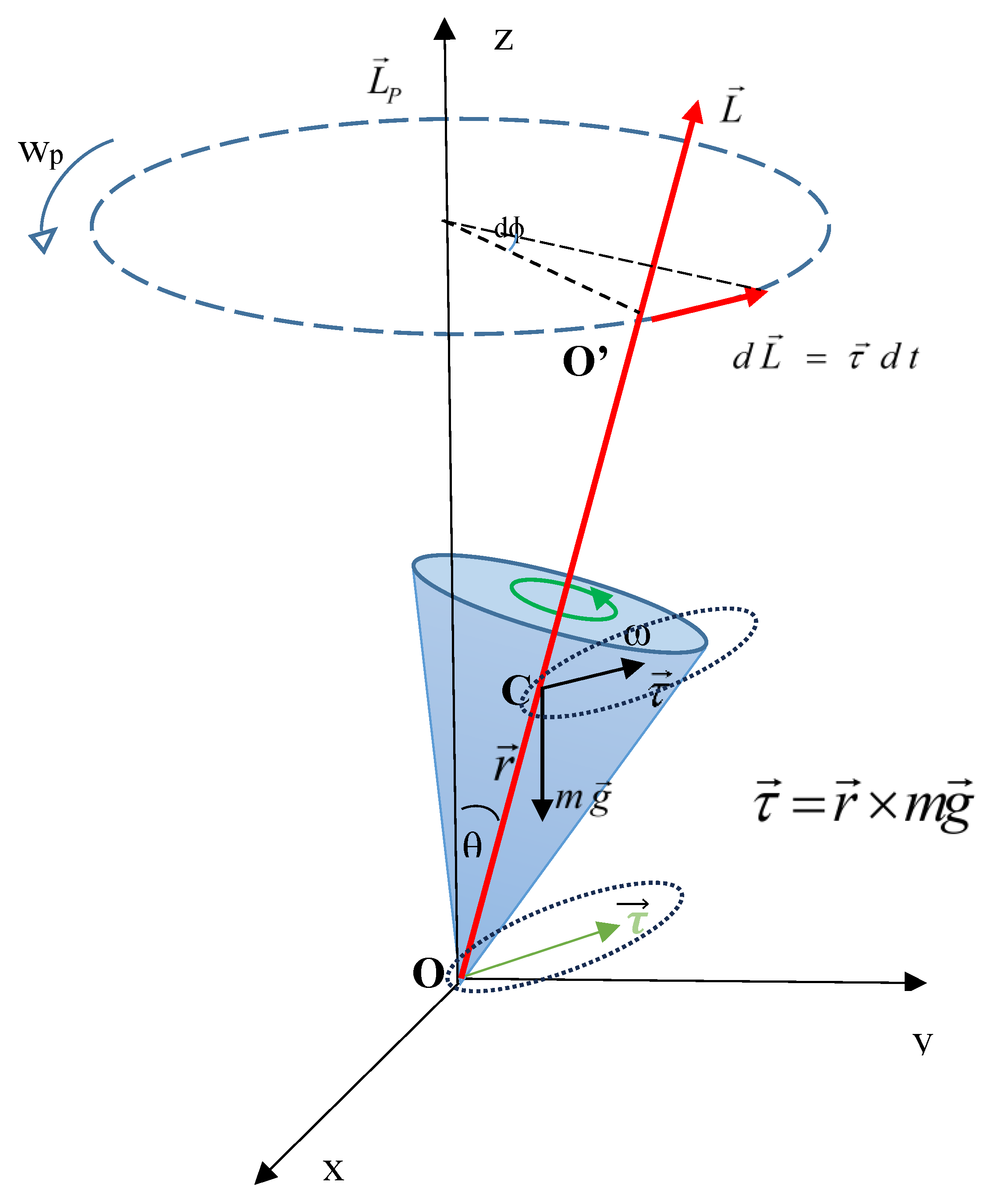
Figure 2.
The apparatus consists of a wheel W of mass m, mounted at the end of cylindrical rod R. The mounting is such that W would freely rotate around an axis through the center of R. Initially, R is firmly bolted at P to the vertical shaft S, thus making it a rigid mounting. Subsequently, R is pivoted to S at point P such that R could freely move up and down in the vertical plane. S is vertically mounted on a bearing at the base B, such that it could freely rotate around the vertical axis for all the experiments described in this paper. Two strain gauges X and Y are mounted on R as shown. Laser displacement sensor is fixed to S as shown, in order to measure vertical movement of the R with respect to the fixed reference point while rotating around S. The distance value d is acquired wirelessly using Bluetooth (BT) signal.
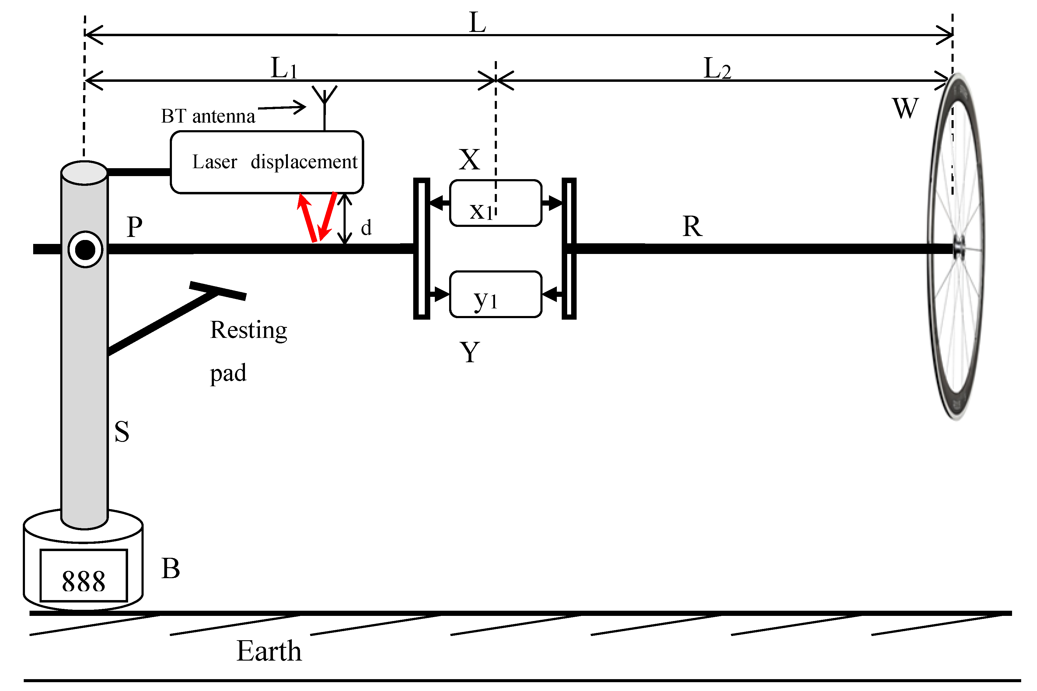
Figure 3.
Simplified diagrams of Exps. 1-3. (a) Exp. 1: R is fixed at point P. Readings of Strain gauges x and y are tension (Ts – tension at stationary position of R-W) and compression (Cs – compression at stationary position of R-W) respectively. (b) Exp. 2: R is fixed at point P. Wheel was rotated around 20 rad/s. Readings of strain gauges x (TR – tension at stationary position of R-W with rotating W) and y (CR – compression at stationary position of R-W with rotating W) remain the same. The bending of R was drawn enlarged for easy understanding of (a) and (b). (c) Exp. 3. R is pivoted at point P. The wheel was rotated around 20 rad/s. R-W starts to revolve around S. The revolving plane of R can be set to any desired angle on the vertical plane, but was kept horizontal for reference. Readings of Strain gauges X (CL – compression at stationary position of R-W when revolving R-W about P with rotating W) and Y (TL – compression at stationary position of R-W when revolving R-W about P with rotating W) flipped (reversed each other) as tension (T) and compression (C) respectively.
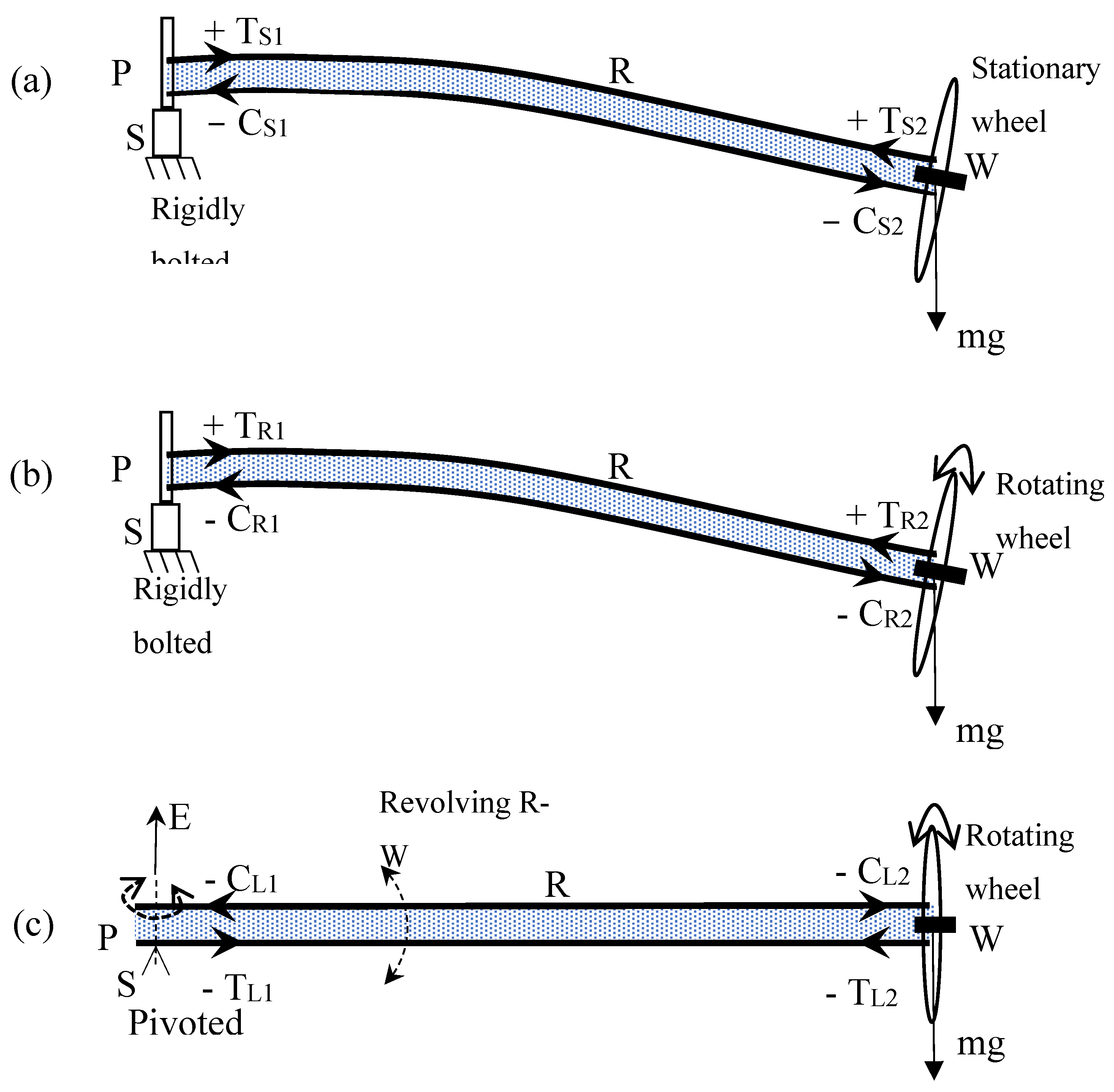
Figure 4.
Wheel W is turned by a remotely controlled RC electric motor, as depicted in this setup. To illustrate the self-precession of the rod and wheel with minimal force, a counterweight is affixed to the opposite end of the rod.
Figure 4.
Wheel W is turned by a remotely controlled RC electric motor, as depicted in this setup. To illustrate the self-precession of the rod and wheel with minimal force, a counterweight is affixed to the opposite end of the rod.
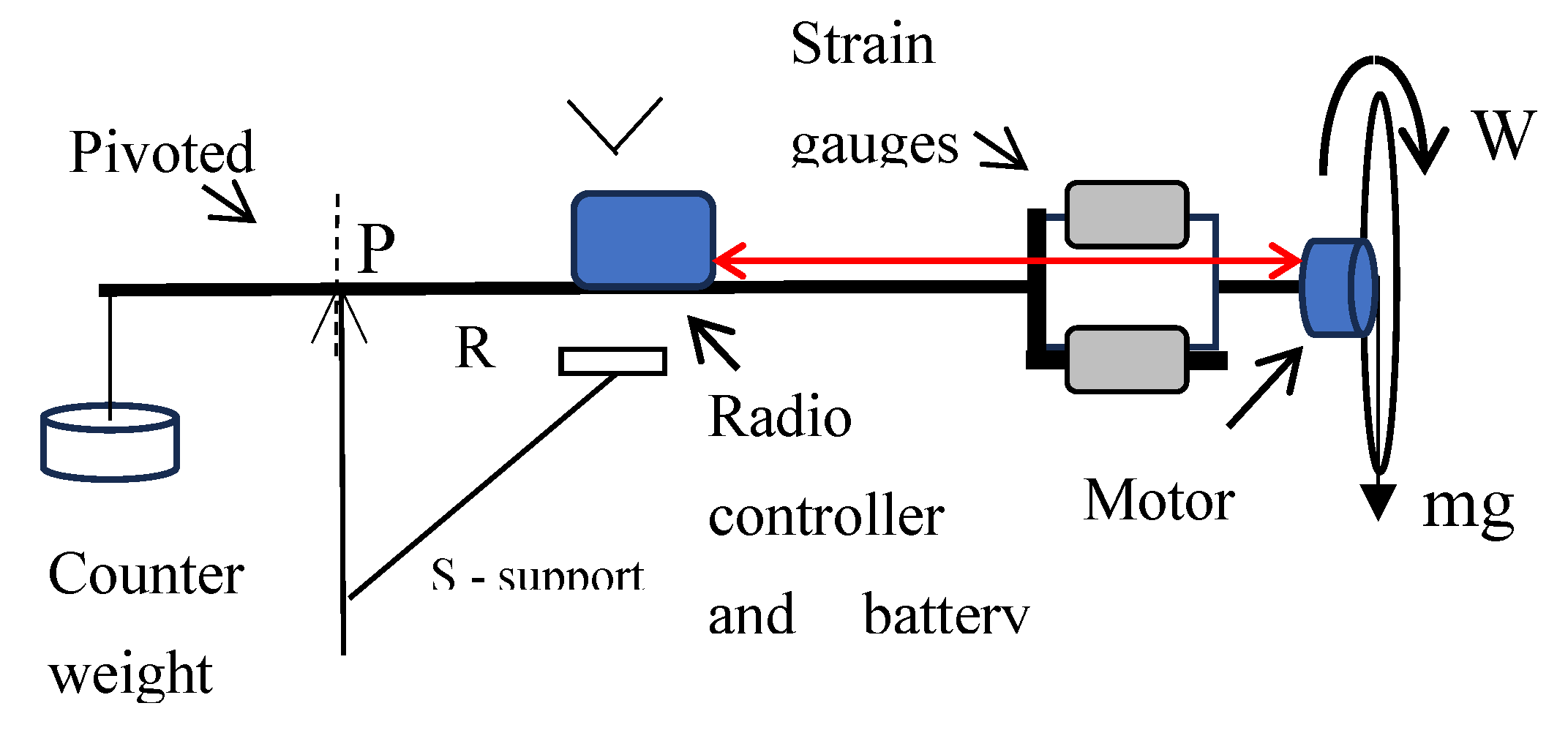
Figure 5.
Exp. 4 tension and compression force distribution along R for different L1/L2 ratios (i) when R is still in red and blue (similar to Exps. 1 or 2) and (ii) when R is rotating in green and black (similar to the Exp. 3). When R-W rotates, note that compression and tension along R switch to tension and compression, respectively.
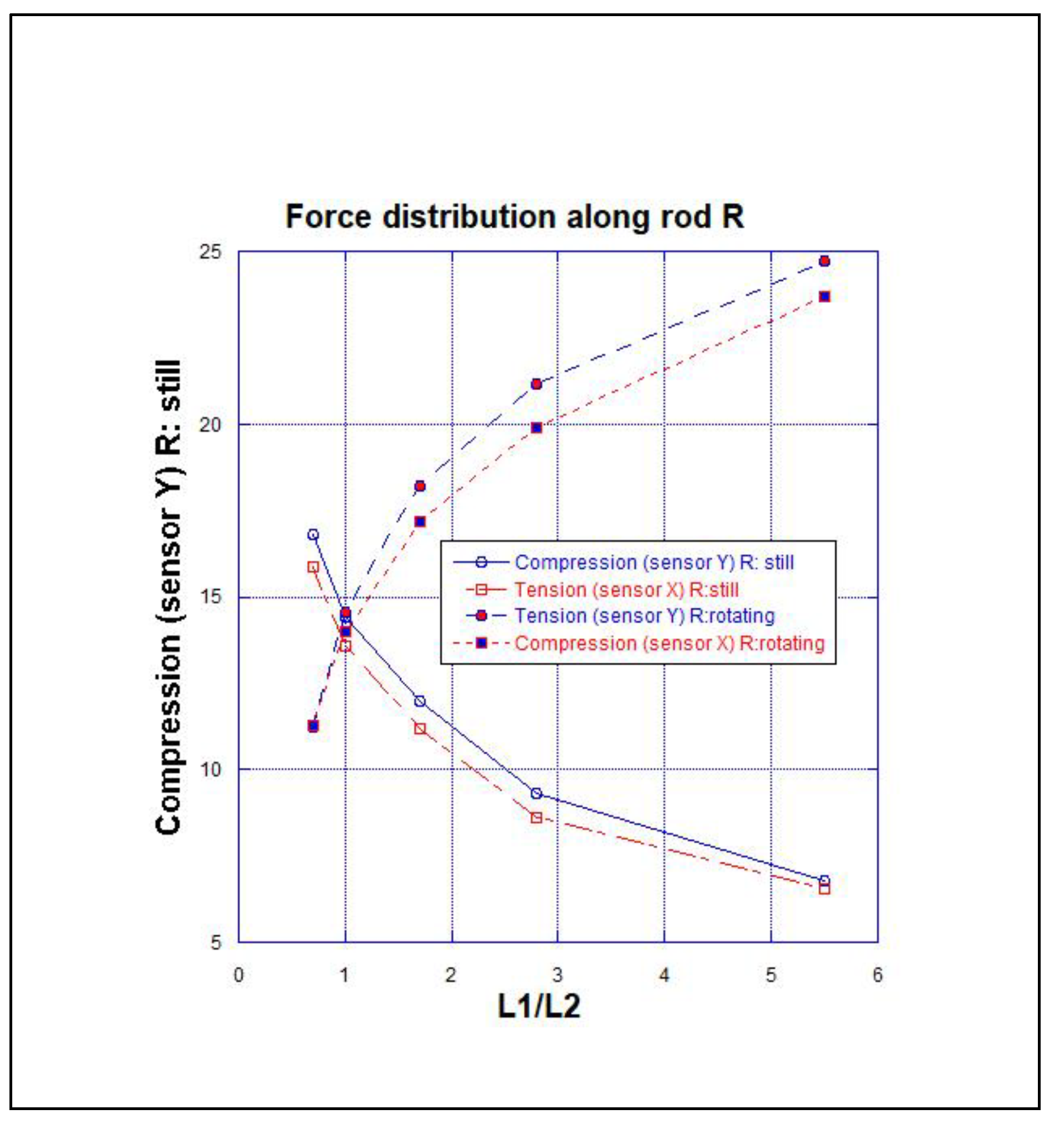
Figure 6.
Angular velocity of W around the axis of L and angular velocity of R-W around the vertical axis S in seconds with respect to the length L of R. .
Figure 6.
Angular velocity of W around the axis of L and angular velocity of R-W around the vertical axis S in seconds with respect to the length L of R. .
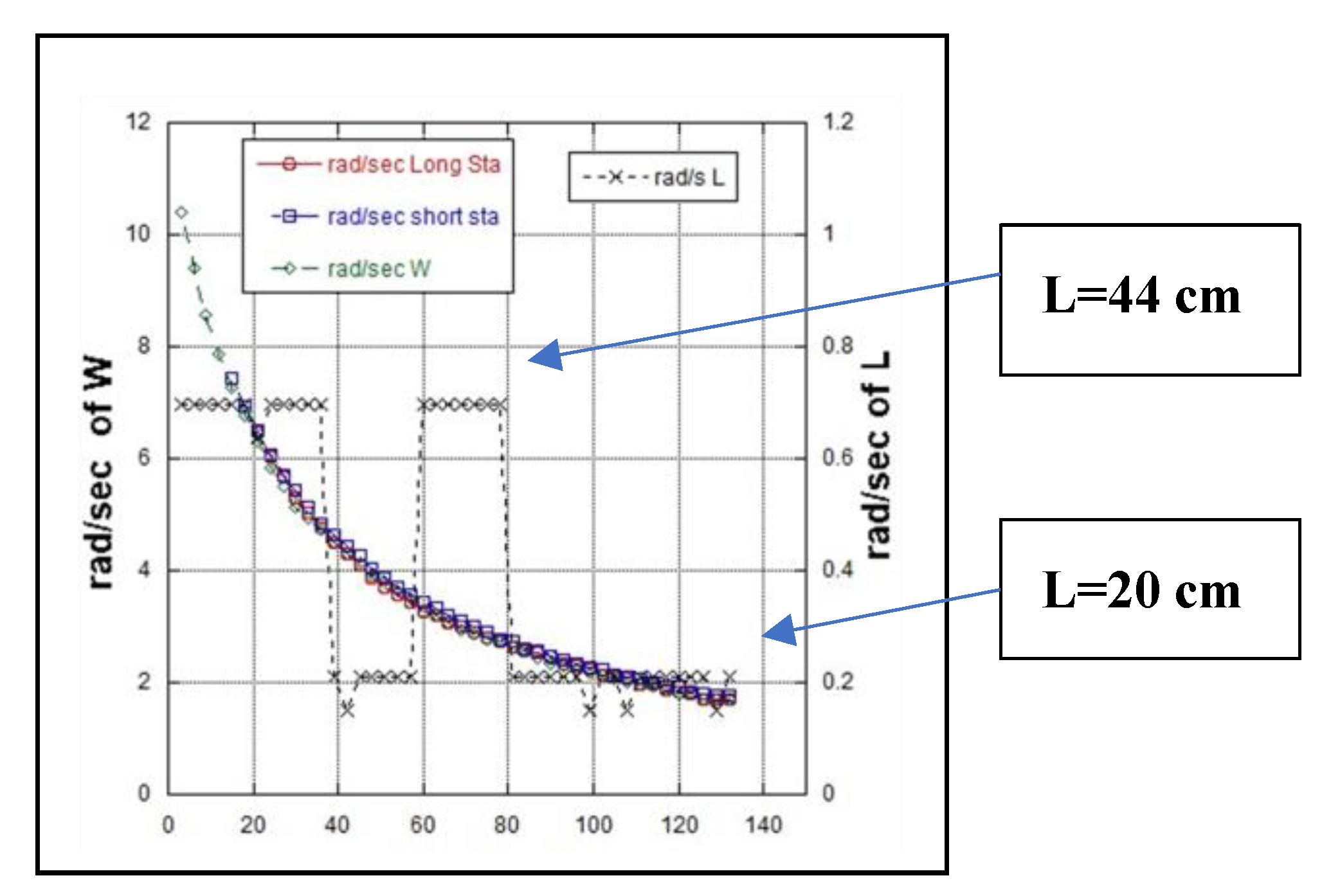
Figure 7.
d vs. time: (a) d is plotted vs. time duration of vertical motion of R, from the start to the end where R stops on the rest pad; R has begun to touch the rest pad ~ 25 s from the start and completely at rest ~ 40 s, though W continues to rotate. (b) Expanded view of (a) from 18 to 20 s. Sinusoidal frequency ~ 2.72 Hz was observed. (c) Expanded view of (a) from 40 to 50 s. No sinusoidal oscillation is noticed. (d) Expanded view of (a) from 40 to 42 s.
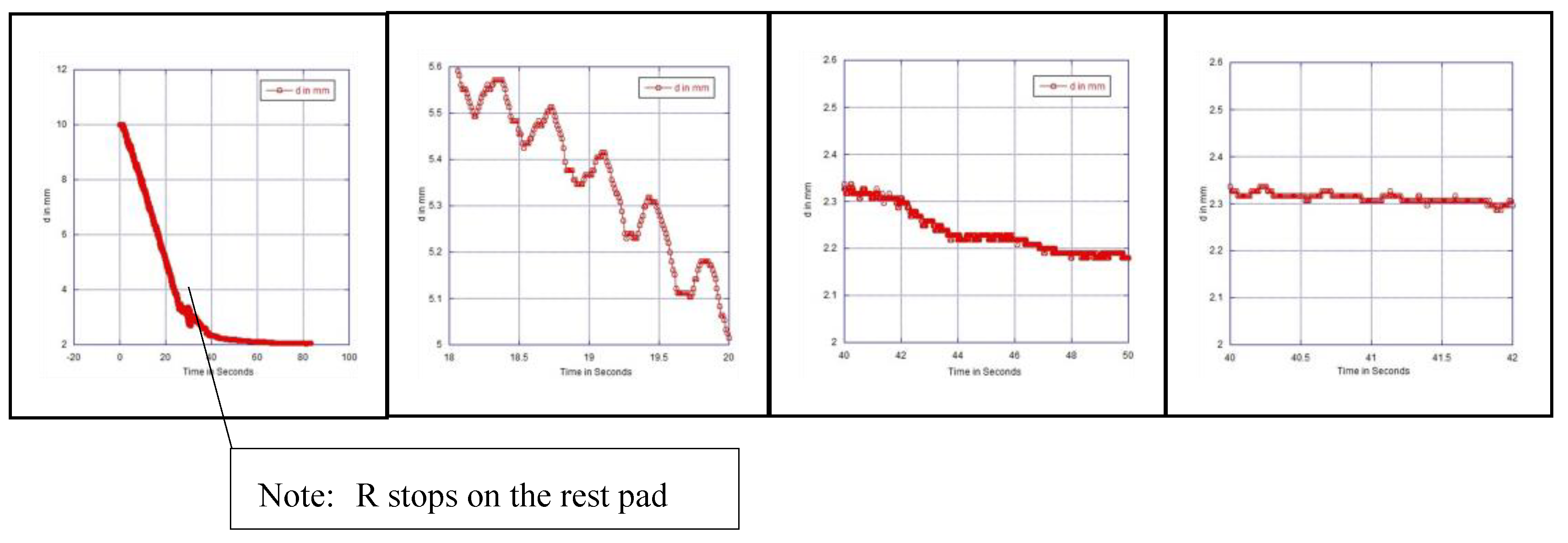
Figure 8.
Forces acting on set-up shown in Figure 3(c) according to the accepted classical mechanical laws.
Figure 8.
Forces acting on set-up shown in Figure 3(c) according to the accepted classical mechanical laws.
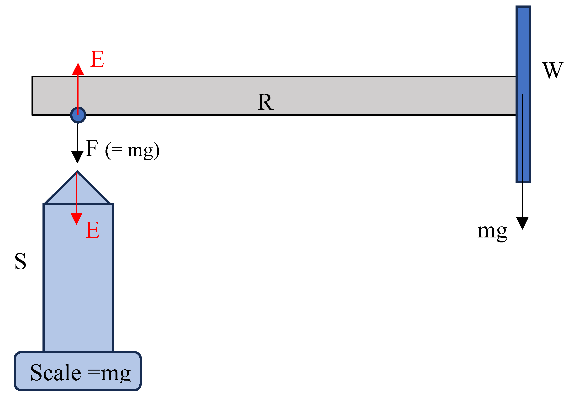
Figure 9.
The physical representation of Intrinsic spin (ISpin) energy of a particle that produces an intrinsic and energy fields surrounding it.
Figure 9.
The physical representation of Intrinsic spin (ISpin) energy of a particle that produces an intrinsic and energy fields surrounding it.
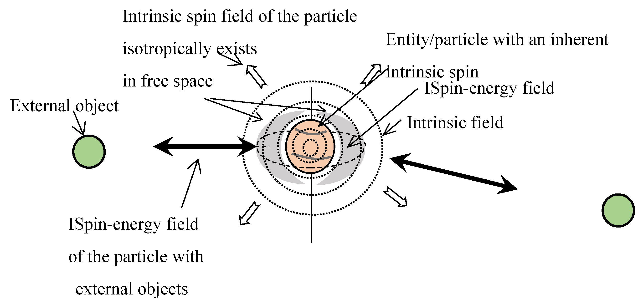

Table 1.
Readings of the strain gauges X and Y for Ex. 1 – 3.
| Experiment | Strain Gauge Readings /N | Remarks | |
|---|---|---|---|
| X | Y | ||
| Exp. 1: R is horizontally bolted rigidly to S at P. | + TS 10.39 | - CS 10.02 | This is the classically expected result. |
| Exp. 2: R is horizontally bolted rigidly to S at P. Wheel rotates at 20 rad/s. | + TR 10.39 | - CR 10.02 | R-W stays still. Readings of strain gauges do not change. This also is the classically expected result. Even when R-W is rotated manually around S, it remains in the position. |
| Exp. 3: R is pivoted to S at P. Rod R can move freely in vertical plane. Wheel rotates at 20 rad/s. | - CL 8.4 | + TL 7.9 | R-W begins to:rotate at 2 rad/s,levitate.Signs of readings of strain gauges are inverted. This observation cannot be classically explained. |
Sign convention: + tension, - compression
Table 2.
Exp. 4:Strain gauge readings with respect to their position along the rod R.
| Experimental Condition | Strain Gauge | Strain Gauge Readings /N | ||||
|---|---|---|---|---|---|---|
| L1/L2 Ratio | ||||||
| 0.7 | 1.0 | 1.7 | 2.8 | 5.5 | ||
| R-W is not rotating (similar to Exps. 1 and 2) | X | + TS 16.81 | + TS 14.43 | + TS 12.00 | + TS 9.33 | + TS 6.76 |
| Y | – CS 15.85 | – CS 13.59 | – CS 11.20 | – CS 8.62 | – CS 6.53 | |
| R-W is rotating (similar to Exp. 3) | X | – CL 11.24 | – CL 14.57 | – CL 18.19 | – CL 20.66 | – CL 24.72 |
| Y | + TL 11.26 | + TL 14.00 | + TL 17.20 | + TL 19.62 | + TL 23.67 | |
Sign convention: + tension, - compression
Disclaimer/Publisher’s Note: The statements, opinions and data contained in all publications are solely those of the individual author(s) and contributor(s) and not of MDPI and/or the editor(s). MDPI and/or the editor(s) disclaim responsibility for any injury to people or property resulting from any ideas, methods, instructions or products referred to in the content. |
© 2024 by the authors. Licensee MDPI, Basel, Switzerland. This article is an open access article distributed under the terms and conditions of the Creative Commons Attribution (CC BY) license (http://creativecommons.org/licenses/by/4.0/).
Copyright: This open access article is published under a Creative Commons CC BY 4.0 license, which permit the free download, distribution, and reuse, provided that the author and preprint are cited in any reuse.


