
Submitted:
14 August 2024
Posted:
20 August 2024
You are already at the latest version
Abstract
This research will investigate how heat treatments affect the behaviour of 3D printed gears made from Polyamide 6 (PA6), a thermoplastic polymer with excellent mechanical properties. However, imperfect structures can result from the 3D printing process, which involves rapid cooling of the molten polymer. Gears were manufactured from PA6 by means of a dedicated 3D printer and their behaviour in gears was then analysed by means of various specific test protocols. Some of the gears were subjected to annealing heat treatments to determine material behaviour, which was a key aspect of this study. Finite Element Analysis (FEA) was used to investigate the effect of heat treatments on the mechanical properties of PA6 thermoplastic material, specifically in the area of 3D printed gear mechanisms. The simulations included both static and transient conditions to determine the influence of different heat treatments on the mechanical properties of PA6. Through the use of comprehensive FEA, the research investigates the deformation, stress distribution and strain rates in 3D printed gears and elucidates the correlation between the mechanical properties and the contact pressure on the tooth flanks during gear operation. As conclusion the study mainly uses numerical simulations based on mechanical characteristics determined in our laboratory. The contribution of the study lies in the novelty of highlighting, through the results obtained, the influence of heat treatments on wear and mechanical stress related factors.
Keywords:
Polyamide 6 (PA6)
; 3D Printing
; Heat treatments
; Annealing
; Mechanical properties
; Polymer gears
; Finite Element Analyses
; Numerical Approach
; Stress Distributions
1. Introduction
This comprehensive introduction sets the stage for a detailed exploration of the impact of heat treatments on the mechanical properties of 3D-printed PA6 polymer gears, providing a roadmap for readers to navigate through the intricacies of the research.
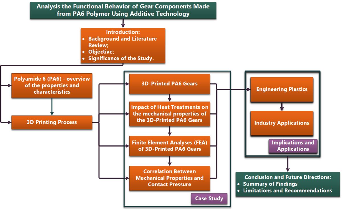
To make it easier to understand the content of this article and the logical steps followed, the content has been summarised in a graphical abstract shown in Figure 1.
1.1. Background and Literature Review
The introduction of 3D printing has revolutionised the manufacturing industry offering unprecedented flexibility and precision.
PA6 stands out for its superior mechanical properties among the many materials used in this process. However, the rapid cooling associated with 3D printing of PA6 can lead to structural imperfections, and further research into optimisation techniques is required. With a focus on achieving improved mechanical strength, this research aims to elucidate the effect of heat treatments on the mechanical properties of 3D printed PA6 [1,2,29].
Expanding research efforts to include plastic gears is essential for enhancing our understanding of how these materials perform under different operational conditions. This broader investigation can contribute to refining plastic gear designs and developing specific guidelines and methodologies for assessing and optimizing their performance using advanced analytical tools such as the finite element method as can be seen in the literature review. Consequently, this academic expansion has the potential to facilitate advancements in the design and application of polymer gears in various engineering and industrial contexts.
In their study, Vivek Karaveer and his co-authors [3] investigate tooth stress in intermeshing cylindrical gears to determine the maximum contact stress in the gear teeth. They use FEA to compare their findings with the theoretical values obtained from the Hertzian equation. The gears under examination are cylindrical in design and are made of materials such as steel and grey cast iron.
Rahul M. and D. P. Kamble [4] utilize the finite element method to analyze a set of cylindrical gears to determine their wear level. The Archard equation is for wear assessment used, and the numerical results are with experimental data compared. The material considered in this analysis is steel.
Rajeshkumar S. and Manoharan R. [5] present the results of FEA on cylindrical gears made from composite materials (glass fiber/epoxy). The Ansys 2023 parametric design language (APDL) was used to conduct the analysis. The study found that rotational speed is a significant parameter that influences the stress state of the gears. Three rotation speeds were in the simulations employed. The study shows that composite material is a superior choice compared to plastic and can even be a viable alternative to steel.
Bergant Z. et al. [6] present an engineering study on the fatigue and wear characteristics of carbon fiber-reinforced polymer (CFRP) gears. The study investigates the potential of CFRP gears as lightweight and high-performance alternatives to traditional gear materials. The wear test outcomes indicate the occurrence of adhesive wear and three-body abrasion wear mechanisms between the CFRP gears and their steel counterparts.
The aim of the paper [7] is to highlight the effect of the use of a composite body on the behaviour of hybrid metal-composite gears during engagement. The proposed model compares a hybrid pinion gear with a lightweight steel gear of the same mass to investigate the influence of the composite body on the stiffness of the gear. In the FEA simulations, the gear body is represented as a sequence of unidirectional layers of symmetrical composite, resulting in quasi-isotropic properties.
Recent years have seen the development of many polymers, which has led to extensive research into finding optimal materials for gears. Muratovic E et al. [8] explore the potential use of Polyvinylidene fluoride (PVDF) in gear applications and introduce an experimental setup to monitor the temperature generated during gear engagement. The study highlights the use of UVDI 2736 to analyse tooth root stress and determine flank tooth pressure precisely. The investigation concludes that gears may fail due to elevated temperatures when Polyvinylidene fluoride is used. This tendency is more noticeable when there are substantial torsional moments, which increases the friction coefficient between the gear flanks.
The VDI2736 German standard [9-12] highlights viable analytical solutions for polyamides (PA) and polyoxymethylene (POM), as emphasised in [8]. However, it lacks sufficient data for the use of other types of polymers in the context of cylindrical gears.
Further research and development in the field is necessary due to the limitations mentioned. Industries are exploring a broader range of polymer materials for gear manufacturing. The analytical solutions provided by VDI2736 for polyamides and polyoxymethylene serve as a foundation. However, there is a clear need to expand the standard to encompass a more diverse set of polymers commonly encountered in cylindrical gear applications. This expansion would contribute significantly to the comprehensive understanding and effective utilization of various polymer materials in gear design and manufacturing.
Hybrid couplings, which involve both plastic and steel components, are commonly used in engineering applications. Zhong B. et al. [13] conducted a comprehensive investigation into the degradation mechanisms of polyoxymethylene (POM) material by performing durability tests under diverse loading conditions. The study focuses on identifying the mechanism responsible for material degradation, specifically linked to contact fatigue. Contact fatigue is characterized by wear and damage resulting from repeated contact and loading cycles and is a critical factor affecting the performance and structural integrity of POM in mixed plastic-steel couplings.
Assessing noise levels in steel gear pairs is a common practice. This study explores the noise levels of the polymer couple POM/PA66 in detail [14], based on an experimental method. The researchers analysed the noise level generated by gears made from the combination of polyoxymethylene (POM) and polyamide 66 (PA66), comparing it with traditional steel gears. This approach significantly contributes to understanding the impact of noise levels in the use of POM/PA66 plastic gears, offering concrete and detailed data about their behaviour compared to traditional steel gears. The results obtained can be valuable for optimizing the design and selecting materials for specific applications where noise reduction is a crucial criterion.
Damijan Zorko's study [15] examines the dynamics of cylindrical gears, with a focus on those made from plastic materials. The study highlights the importance of manufacturing quality in the operational performance of these gears. The investigation includes both experimental methodologies and numerical simulations, using the finite element method and the ANSYS 2023 program.
The study concludes that injection and cooling temperatures have a significant impact on the operational behaviour of plastic gears. Delrin 100 NC010 (POM-H) is identified as a suitable material for gears due to its robust fatigue resistance, minimal wear characteristics, and reduced coefficient of friction. The properties of the material contribute to its widespread use in gears, making it a preferred choice for applications where reliable performance is essential.
The lifespan of gears depends on the wear degradation process. Tunalioglu and Agca [16] conducted a comprehensive study on the wear behaviour of three materials integrated into cylindrical gears: polyethylene terephthalate (PETG), polylactic acid (PLA), and acrylonitrile butadiene styrene (ABS). Wear was assessed experimentally using a ”Forschungsstelle für Zahnräder und Getriebebau” (FZG) type device. The study's conclusion suggests that gears made from ABS and PLA have a shorter lifespan compared to the third material, even when subjected to identical demands.
Upon detailed analysis of wear behaviour, significant differences were found among the materials. The experimental findings were supported by analytical analysis, indicating that the reduced durability of gears made from ABS and PLA may be due to their more pronounced wear characteristics under similar operating conditions. The study presents a comprehensive perspective on the wear performance of PETG, PLA, and ABS materials in the context of cylindrical gears.
1.2. Objective
Investigating how heat treatments affect the mechanical properties of 3D printed PA6 samples is the main objective of this research. Through the use of a dedicated 3D printer and specific test protocols, the aim of the study is to systematically analyse the behaviour of the material under different conditions. The key role of heat treatments in the improvement of mechanical strength is a focal point, with the aim of a deeper understanding of the mechanisms at play.
1.3. Significance of the Study
The potential to advance the field of engineering plastics is the significance of this research. The study provides valuable insights into the development and application of these techniques in industrial settings by revealing the transformative effects of heat treatments on 3D printed PA6. These results may lead to improved manufacturing processes and to PA6 being used in critical applications where mechanical strength plays a key role.
2. Materials and Methods
2.1. Polyamide 6 (PA6)
The basis for the understanding of the material under investigation is an overview of the properties and characteristics of PA6. In relation to its thermoplastic nature, this section explores the mechanical strengths and limitations of PA6 in the context of 3D printing.
Typically, polymers are processed by cooling the melt from rapid melting temperature to room temperature, causing the polymer chains to struggle for equilibrium.
One of the most commonly used engineering plastics is PA6. It plays an important role in many areas such as the automotive, textile and packaging industries due to its unique combination of excellent mechanical properties, chemical resistance, self-lubrication and barrier properties. A key role in these excellent properties is generally recognised to be played by hydrogen bonding interactions resulting from amide groups between adjacent PA6 chains. Due to the presence of amide groups, PA 6 absorbs significant amounts of water, up to approximately 10% by weight. The material used for the tests was PA6 without any additives. The following subsection 2.2 presents the basic parameters used for the 3D printing process.
2.2. 3D Printing Process
The intricacies of the 3D printing process, specifically tailored for PA6, are elucidated in this section. The focus is on the rapid cooling phase and its implications on the final structural integrity of the printed samples.
The Raise E2 3D printer (Figure 2.a) from the Additive Technologies Laboratory of the Mechanical and Electrical Engineering Faculty was used for the printing of the samples, and a PA6 Neat roll (Figure 2.b) was used for the printing of the large number of gears.
The main properties used for the production of the gears are those recommended by the manufacturer (Spectrum Industrial) and are shown in Table 1 [17].
PA6 polymer is used when the temperature limit is reached or the hydrolytic stability of PA6 is insufficient. It provides good surface appearance and good adhesion, resulting in burst pressure resistance. An economic advantage is that printing cycles are fast.
PA6 is often used to replace metal in automotive parts where design flexibility, temperature and chemical resistance are critical due to its good processability. Lastly, they contribute to weight reduction, offering opportunities for CO2 reduction.
2.3. Test Protocols
The choice of materials for a technical application, in this case the manufacture of gear wheels in PA6 polymer, must be based on two principles:
- the materials selected must have physicochemical, mechanical and technological properties that meet the requirements of the application;
- the technical solutions for the intended use, in terms of their economic viability, in terms of development, semi-manufacturing and manufacturing costs.
The study also suggests that an annealing treatment can be applied to the gears for use in engineering applications.
Some improvements in the mechanical properties are observed when the temperature of the deposition bed is changed from 60 °C to 85 °C, but the changes do not have a radical effect on the mechanical properties. The 3D printed PA6 gears were subjected to an annealing heat treatment between 60°C and 200°C with air cooling.
In the scientific literature, it was found that the optimum temperature range characteristic of the annealing heat treatment was between 120 °C and 160 °C, based on the mechanical tests carried out on these samples.
Heat treatments are used to enhance the mechanical properties of structures made of PA 6 plastic material obtained through the 3D printing process, with a focus on improving tensile strength and yield strength. It should be noted that these treatments also cause minor changes in elastic properties, as explained in the preceding sections. This paragraph examines the impact of thermal treatments on the mechanical and elastic properties of PA6 materials and their effect on the operational behavior of cylindrical gears.
Highlighting the importance of this complex analysis, a case study has been conducted on a mechanical engineering benchmark, a PA6 polymer gears. A detailed study, based on FEA software simulations through Ansys 2023 and on the provisions of standards specific to mechanical parts made from this type of material, is presented below for a gearbox consisting of two such 3D-Printed Gears.
Optimization is crucial for ensuring the reliability and performance of components manufactured through 3D printing, particularly those designed for applications involving mechanical stresses, such as cylindrical gears.
The study of operational behavior involves three primary methodologies: numerical, analytical, and experimental. Traditionally, the predominant focus in gear studies has been on metallic materials, particularly steel. The use of the finite element method (FEM) is prevalent in evaluating the performance and durability of gears, but there is a lack of research dedicated to analyzing gears made from plastic materials.
Currently, there are numerous studies on the operational behavior of gears, using the finite element method to varying degrees. Most of these studies focus on assessing gears made of steel, with relatively fewer investigations dedicated to examining gears made of plastic materials. Although studies on steel gears provide valuable insights into mechanical performance, the growing use of plastic materials, especially in applications such as 3D printing, requires a more comprehensive examination of the operational behavior of plastic gears.
When applying the Finite Element Method (FEM) to analyze gears manufactured through 3D printing technology, it is crucial to have a nuanced understanding of the intricate relationships between several critical factors. These factors include the precision of FEM results, the definition of boundary conditions, the material characteristics intrinsic to the gears, and the accuracy of the geometric model.
The mechanical behavior and thermal properties of 3D-printed gears have a significant impact on their performance in different operational scenarios. It is essential to consider these material characteristics carefully to accurately replicate the mechanical response of the gears in a simulated environment.
Therefore, a robust Finite Element Analysis of 3D-printed gears requires a holistic approach. This requires precise calibration of boundary conditions, a comprehensive understanding of material properties, and the creation of a geometric model that accurately reflects the actual structure. This approach not only improves the accuracy of the simulation but also offers valuable insights into the performance and structural integrity of 3D-printed gears in practical applications.
3. Results and Discussion
3.1. Finite Element Analyses of 3D-Printed Gears
Cylindrical gears made from plastic materials are often produced through the injection molding process, which is recommended for large-scale production runs. However, the gears being studied in this research were manufactured using the 3D printing process. Specifically, the material used was PA6, which was enhanced through a heat treatment process. These gearwheels have been included in an experimental setup for future tribological research (Figure 3).
Figure 4 and Table 2 present the geometrical characteristics of the gears that were analysed numerically (using FEA).
The decision to use 3D printing instead of injection molding for the cylindrical gears is significant as it deviates from the conventional manufacturing method. Injection molding, which is usually preferred for its mass production efficiency, is replaced by the AM process, highlighting the distinctive benefits of 3D printing technology.
The gears are made of PA6 material, which undergoes a heat treatment process to improve its properties. The decision to use heat treatment demonstrates a deliberate effort to customize the material properties to meet specific performance requirements.
Figure 4 provide a comprehensive representation of the design of the 3D-printed gears, highlighting their geometric intricacies. Table 2 presents detailed specifications that offer a quantitative insight into various geometric parameters critical for the evaluation of the gears' performance. This information complements the visual representation (Figure 5).
The characteristics for the material used to make the gears are in Table 3 detailed, depending on the temperature values at which the heat treatment was conducted. Table 3 contains data obtained on the basis of tests performed by the authors in their own laboratories, and the results are confirmed by the values reported in the literature, so that the sources cited in brackets certify the veracity of the results obtained.
A geometric model (3D) was created using AutoCAD Inventor 2024® (Educational Version) for the purpose of numerical analysis. The model was then transferred to Ansys SpaceClaim in the STL file format.
FEA on gear plastic wheel is often used to obtain detailed information about a system's behaviour over time, using the transient analysis method [21].
The analysis framework used was the quasi-static model. To increase accuracy and reduce runtime, only a portion of the entire model was for analysis retained.
This portion includes five teeth for both the pinion and the driven gear, which will be engaged throughout the analysis. The appropriate boundary conditions were set and are presented below.
A three-dimensional model was used for numerical analysis, assuming homogeneous and isotropic materials. Torsional moments were applied to the pinion-wheel assembly with magnitudes of 3,000 Nmm, 5,000 Nmm, 6,000 Nmm, and 7,000 Nmm. The rotational speed considered was v = 100 rotations/min. The assumed coefficients of friction [1,22] between the pinion and the driven gear are 0.2, 0.28, 0.31, 0.35, and 0.28, respectively.
These assumptions form the basis for a comprehensive numerical analysis aimed at evaluating the mechanical behaviour of the system under different operating conditions. It is important to note that the assumption of homogeneity and isotropy in the materials simplifies the model, allowing for a more manageable mathematical representation. The applied torsional moments and coefficients of friction were thoroughly explored to understand the system's response to various loading scenarios.
To achieve accurate numerical results, we paid meticulous attention to selecting input data and discretization parameters. The precision of the outcomes depended heavily on factors such as material characteristics, boundary conditions, and underlying assumptions. We also carefully considered finite element types and sizes, especially in regions with maximum stress.
3.2. Sensitivity Analyses
To determine the optimal size of finite elements for precise results, sensitivity analyses were conducted [23]. This involved systematically varying the dimensions of finite elements according to Table 3. During the discretization process, critical parameters such as the shape of elements, maximum aspect ratio, and maximum corner angle were thoroughly examined.
The aim of this detailed investigation was to determine the impact of these parameters on result accuracy.
The sensitivity analyses involved creating multiple discretization models with varying finite element sizes, while maintaining consistent boundary conditions across all models. These conditions were rigorously applied to ensure a fair comparison. Subsequently, analyses were conducted on each model, and the results were meticulously compared with analytical solutions obtained through various methods such as the Lewis Bending Equation, KISSsoft approach, and Classical beam theory.
As shown in Figure 6, Figure 7, and Table 4, the discretization model using finite elements with element dimensions of 0.1 mm in the regions corresponding to the contact between the pinion and the driven gear closely aligns with the analytically obtained results. The bending stress is prominent at the base of the engaged tooth, and analytical calculations exhibit good agreement, especially in the case of the KISSsoft approach and Classical beam theory (only 3.34 %). Regarding the differences in bending stress between FEA and KISSsoft, the difference is 1.7 % (and 5.22 % between FEA and Classical beam theory).
This indicates that the discretization model with 0.1 mm finite element dimensions in the contact regions between the pinion and the driven gear (Figure 6.d) yields results that closely align with those obtained analytically. Regarding bending stress, there is notable agreement, particularly when comparing the KISSsoft approach and Classical beam theory, with minimal discrepancies between finite element analysis (FEA) and analytical methods.
The maximum differences observed, especially in the comparison between FEA and Lewis Bending Equation (Figure 8), are within a reasonable margin of 25 %, highlighting the reliability of the finite element analysis results.
The significance of the notations used in the evaluation of bending stress within Table 4 is: σ - bending stress [MPa]; Ft - pinion tooth force [N]; t - tooth thickness at base [mm]; I - inertia moment of the cross-sectional area of the tooth [mm4]; Scf - Stress concentration factor at tooth root, Scf = 1.25 [10]; l - dedendum [mm]; w - face width [mm]; m - wheel teeth module; Y - The Lewis factor depends on the number of teeth and the pressure angle. For the studied gear [19], it is as 0.36 reported.
The study ensured the reliability and precision of the simulation outcomes by benchmarking the numerical results against established analytical methods. This approach enhanced confidence in the accuracy of the results and underscored the thoroughness of the methodology employed in the analysis.
In terms of load, the sensitivity analysis models (Figure 6) were subjected to a torsional moment of 3,000 Nmm. The material used was untreated PA6, which is described in Table 3, and the dimensions were in accordance with Table 2.
The pinion and driven gear components were modelled in the numerical model using SOLID185 finite element types, providing a three-dimensional representation. Tooth contact regions were modelled using CONTA174 and TARGE170 elements. CONTA174 is a contact element used to model surface-to-surface contact, while TARGE170 is for target elements in contact analysis used. The MPC184 element type is to define and model boundary conditions used. The MPC184 element, or Multipoint Constraint element, is useful for connecting multiple degrees of freedom at different points, allowing for the accurate representation of complex boundary conditions.
The boundary conditions (Figure 9) adopted are of the 'Joint-Revolute’ type, which represent rotational couplings defined at the shafts of the two gears. These connections enable the rotation of the two gears around their respective axes. The applied rotational moment, introduced on the pinion, is a ‘Joint Moment’ load that is constant with a value of 3 Nm.
On the tooth flanks that are or will engage, the contact is of the 'Friction' type, with a friction coefficient value of μ = 0.4 [1,22] (only for sensitivity analysis).
A 'Friction' contact model is employed for the tooth-to-tooth contact on the engaging flanks. The given simulation uses a friction coefficient of μ = 0.4 [1,22] to represent the interaction between the contacting surfaces. It is important to note that this value is only for sensitivity analysis used. The boundary conditions and contact models together create a realistic representation of the mechanical interactions within the gear system, capturing both the rotational constraints at the shafts and the frictional effects at the tooth contact points. This comprehensive approach ensures a detailed and accurate simulation of the gear behaviour under the specified loading conditions.
3.3. Effect of Heat Treatments on Bending Stress and Flank Contact Pressure
The bending stress values, and contact pressure of cylindrical gear teeth by the geometric configuration of the gear system are influenced, the nature of the loads, and the elastic and mechanical characteristics of the materials involved. The evaluation method for gears made of plastic materials (PA6) is in VDI 2736 specified, introduced in 2014. VDI 2736-2 [10] outlines the procedure for evaluating bending stress in cylindrical gears Based on the equations from Table 5 [10,24,25].
Like the assessment of bending stress, which is obtained at the base of the teeth in contact, contact pressure can be evaluated based on VDI 2736-2.
The equation used for this evaluation is [10,15]:
where: represent the flank pressure at the contact point in [MPa].
When evaluating contact pressure between gears, it is important to consider the elastic material properties. It is crucial to maintain a balanced and objective evaluation of these properties. The elasticity factor, considers material characteristics such as the longitudinal modulus of elasticity and Poisson's ratio. These properties determine how the material responds to the stresses during gear engagement, which affects the overall contact pressure.
The zone factor, , draws attention to the geometric aspects of cylindrical gears in contact. It includes features related to the design and configuration of the gears, providing insights into how their geometry affects the distribution of forces and stresses in the contact area. This factor is crucial for tailoring gear designs to achieve optimal performance and longevity. Moving beyond material and geometric considerations, the contact ratio factor, , delves into the effective contact length between gear flanks. This parameter is particularly significant as it accounts for the duration and extent of contact between the teeth during rotation. Understanding the effective contact length is crucial for predicting wear patterns, fatigue, and optimizing gear designs for durability.
Finally, the factor represents the spiral angle and captures the helix angle of the gears. It usually has a value of one, indicating straight-toothed gears. However, its inclusion highlights the significance of considering gear helix in specific applications. The spiral angle affects tooth engagement dynamics, which impacts factors such as load distribution and noise generation. Evaluating contact pressure requires considering elasticity, geometry, effective contact length, and helix angle factors. These parameters collectively contribute to understanding the interplay between material properties and gear design, enabling engineers to make informed decisions for optimized gear performance.
The permissible contact pressure [10,15] is determined by the relationship between the fatigue strength of the material,, in contact and the surface roughness, through the factor. is generally equal to unity, and the safety factor coefficient is set at 1.4, which determines the permissible pressure.
Based on the analytical relationships presented earlier, an evaluation of bending stress and contact pressure was carried out using the KISSsoft program which implements the expressions specified in the VDI 2736-2 standard, as well as through numerical analyses (FEA - Ansys 2023) [26]. Simulations were conducted to draw conclusions on the influence of heat treatments on PA6. The study compared untreated PA6 to PA6 that underwent heat treatment at 160 °C annealing temperature. Table 3 and Table 6 present the mechanical and elastic characteristics, respectively, while Table 2 provides the geometric details as previously mentioned.
To compare and validate the simulation results, Table 6 and Table 7 summarize the outcomes. The finite element model in Figure 6 (d) is used, with boundary conditions previously shown in Figure 9.
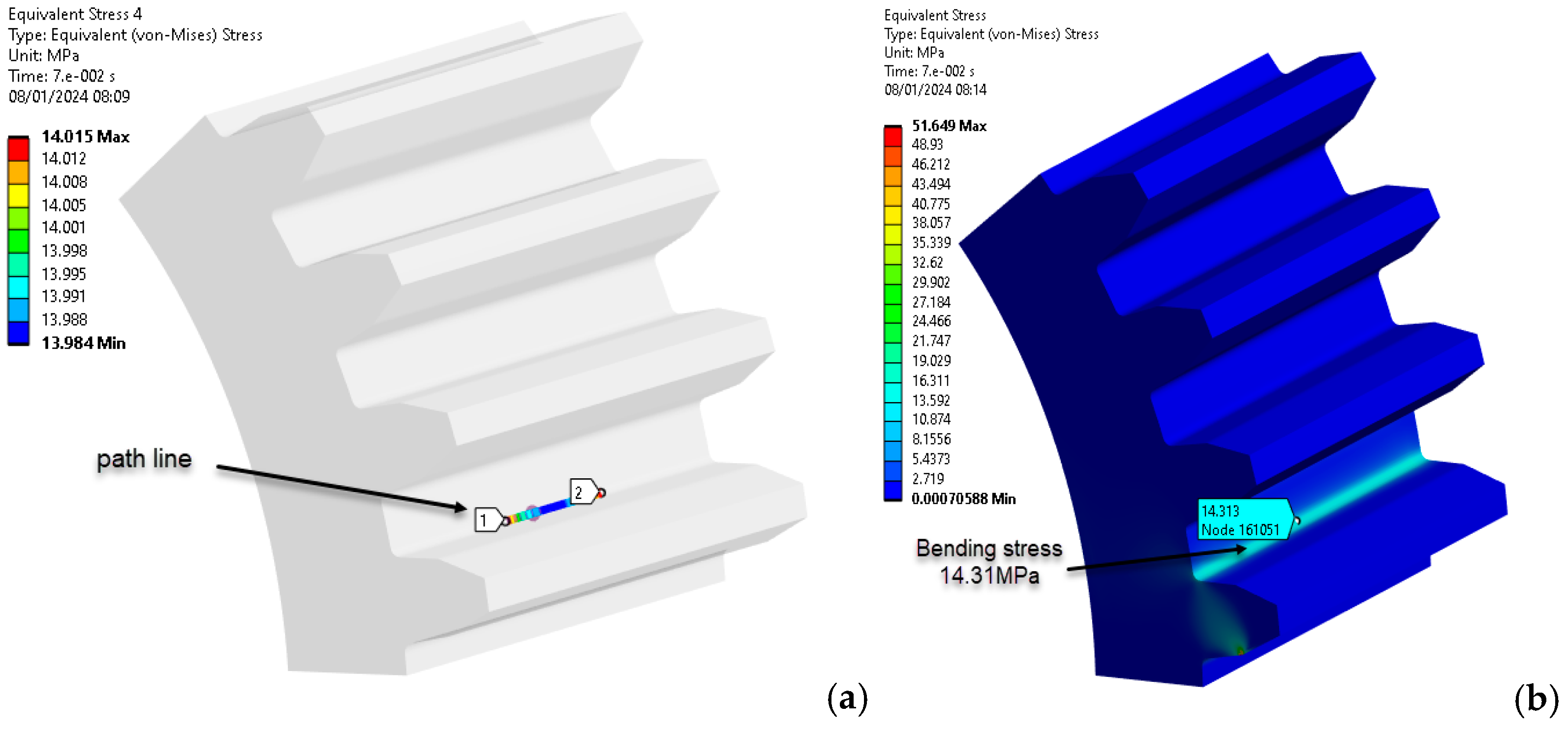
The 'path' command in Ansys 2023 Workbench highlights bending stresses by selecting nodes within the region of maximum load on the tooth, as seen in the Figure 10.
The procedure for identifying and validating the flank stress calculation was in the same way applied. The stresses in the contact zone between the flanks can be found in Figure 11.
The 'path' command in Ansys 2023 Workbench simplifies the selection of nodes that are critical for assessing the maximum stresses in the tooth, enabling a detailed analysis of the variation in equivalent stress.
Figure 12.
Path line and bending stress (PA6, 160 °C annealing temperature): (a) stress on path line; (b) bending stress distribution [MPa] (Source: authors based on the bending stress simulation results).
Figure 12.
Path line and bending stress (PA6, 160 °C annealing temperature): (a) stress on path line; (b) bending stress distribution [MPa] (Source: authors based on the bending stress simulation results).
The data presented in Table 6 and Table 7 show a commendable agreement between the results obtained analytically and those obtained by numerical means, in particular FEA. As expected, the largest discrepancy of 9 % is found in the flank stress calculation. This modest discrepancy is rationalised by the influence of coefficients within the analytical relationships, as prescribed by VDI 2736-2.
The sensitivity of these coefficients is evident, as their selection has a relatively small but noticeable effect on the resulting values. This comparative analysis underlines the robustness of both analytical and numerical methods, while emphasising the importance of careful selection of coefficients in analytical formulations to ensure accurate predictions in engineering applications.
3.4. Effect of Heat Treatments on Wear and Service Life
The primary method for measuring wear involves testing a sample of the material with a rotating ring, using a pin-on-disk tribometer. This technique involves evaluating a material's wear resistance by subjecting it to controlled friction and abrasion processes. A specimen, often in the form of a pin, is pressed against a rotating disk, simulating dynamic contacts resembling real-world operational conditions. Through this apparatus, wear processes can be simulated, allowing for a detailed analysis of the material's response to both frictional forces and abrasive wear. This method provides valuable insights into the material's durability and performance under conditions that mimic practical usage scenarios.
The analysis focuses on three core parameters: the normal load applied to the specimen, the rotational speed of the disk, and the sliding distance travelled by the material against the rotating ring. These factors collectively influence the wear rate, a critical metric that indicates material degradation over time. The Archard wear equation (3) provides a quantitative framework for this assessment, factoring in the volume of material loss, the normal load, and the sliding distance.
where: W [mm3] represents wear volume, K [mm3/Nm] is wear factor (depends on the combination materials); H is the hardness of the gear surface materials; Fn [N] is the normal force and l [mm] is the sliding distance [27].
Abrasive wear is a critical consideration, especially in scenarios involving dry running conditions for cylindrical gears. The absence of lubrication exacerbates the challenges associated with abrasive wear in gear systems. Solid contaminants such as dust and particulate matter have a more direct and pronounced impact on the contacting surfaces of the gear teeth in the absence of a lubricating film. The abrasive particles act as cutting agents, leading to accelerated material removal and surface deterioration. This phenomenon is exacerbated by the absence of a lubricating barrier that could otherwise reduce friction and wear.
VDI 2736-2 highlights local linear wear in cylindrical gears made from plastic materials using the following expression [10,28]:
The symbol denotes the local normal force in [N]; N stands for the quantity of loading cycles; b is the face width in [mm]; is the wear coefficient measured in [mm3/Nm]; [mm] is slippage.
An interesting algorithm for wear assessment is presented in [29,30,31]. The calculation formula, which considers the contact pressure between flanks and sliding distance, is highlighted using the finite element method. The wear assessment formula is defined by the relationship [29,30,31]:
where [29]: h [mm] represents wear depth, is wear rate [mm3/Nm]; P [MPa] is the contact pressure and s [mm] is the sliding distance.
The relationship between wear and wear depth is dependent on the number of loading cycles, as shown by the formula:
where N represents the cycle number. This indicates that in the context of FEA, an iterative calculation is necessary to accurately evaluate wear.
The procedure involves establishing the model associated with the cylindrical gear for assessment, conducting FEA analysis, and determining the initial wear depth, denoted as h (initial). Initial iteration begins by adjusting the original model based on the wear depth and subsequently re-conducting the FEA analysis to determine the updated wear depth. The iterative process continues guided by the principle that modifications are made to the model after each cycle until the predetermined number of cycles is achieved [32].
The connection between the iterative process and wear is significant. As wear progressively affects the geometry and material properties of the system, each iteration reflects an evolving state of the gear mechanism. This iterative cycle enables a dynamic adjustment of the model, considering the changing conditions caused by wear.
The iterative nature of the process is essential due to the reciprocal relationship between wear and the system's response to mechanical loading. The model is iteratively adjusted to account for changes, ensuring that subsequent analyses capture the evolving nature of wear.
To evaluate the impact of heat treatments on the wear behaviour of cylindrical gears with teeth made of PA6 materials, we analysed the geometric model shown in Figure 3. The model has mechanical characteristics as per Table 3, using analytical principles (VDI 2736-2, KISSsoft).
Table 8 presents the results of applying the calculation expressions, specifically Equation 4, for an initial non-iterative calculation and Table 9 presents the results of applying the calculation expressions, specifically Equation 4, for an iterative calculation.
The mechanical characteristics of the materials from Table 8, respectively Table 9, are in Table 3 provided. The considered wear coefficient in the analysis was w = 9 (mm3/Nm) [18,19].
Wear depends on several factors, including contact pressure, which plays a crucial role. The contact pressure (hertzian pressure) values from Table 28 were compared with those obtained through numerical simulation (FEA-Ansys 2023), resulting in a highly favourable correlation, as shown in Figure 13, Figure 14 and Figure 15. This observation highlights the robustness of the simulation results and their alignment with the analytical contact pressure values. This correlation improves the reliability and validity of the data obtained, providing a strong foundation for further analysis and conclusions.
The results presented in Table 8 demonstrate that the assessment of flank wear through non-iterative calculation is not affected by the nature of the PA6 material, indicating independence from heat treatment. Additionally, the other parameters, except for the Hertzian pressure values, which increase with the longitudinal elastic modulus, fall within a relatively narrow range. However, when assessing wear, iterative calculations are necessary. Therefore, data obtained through non-iterative methods may not be as precise and should be with caution considered.
The use of non-iterative simulation results for wear assessment is not preferred due to the lack of objectivity. This is further highlighted by the examination of the wear distribution across the profiles of teeth fabricated from PA6 plastic material, as shown in Figure 16. The distribution was derived for PA6 material that underwent heat treatment with a longitudinal elastic modulus (E) of 6,000 MPa. Figure 16 shows a significant absence of wear at the contact point between meshing teeth. The phenomenon described can be attributed to the simplification inherent in non-iterative simulations. In these simulations, contact is assumed to involve rolling rather than the more realistic sliding behaviour.
The implications of this observation are significant. These neglects the complexities introduced by sliding, which is a more accurate representation of real-world scenarios. Non-iterative simulations may not fully capture the nuances of wear behaviour at tooth contact points. This is especially relevant when dealing with plastic materials like PA6, where wear patterns can be by factors influenced, such as material properties, heat treatment, and contact conditions.
The difference between simulated and real-world wear distributions highlights the need for iterative approaches to capture the complexities of contact behaviour and wear. This ensures a more accurate representation of the physical phenomena involved. Therefore, it is important to exercise caution when interpreting non-iterative simulation results for wear assessment, particularly in contexts where a high degree of precision is required for reliable engineering analyses and design considerations.
When conducting iterative analyses using the same materials and solicitation conditions, the results presented in Table 9 reveal a clear trend. This highlights the discernible influence of the elastic and mechanical characteristics obtained through heat treatments on the wear process. The parameters of local linear wear (µm), wear volume per tooth (mm³), and wear mass per gear (g) increase notably with the longitudinal modulus of elasticity. This highlights the significant influence of the longitudinal modulus of elasticity on wear behaviour, demonstrating a direct correlation between the mechanical properties obtained through heat treatments and the resulting wear characteristics. The iterative nature of the analyses provides a strong basis for asserting the significance of these thermal treatments in influencing wear dynamics. This emphasizes the complex interplay between material characteristics and wear outcomes. The validation of the numerical results for iterative simulations of material loss due to wear is detailed in Table 10. This validation involves comparing the numerical results with experimental data obtained from the set-up shown in Figure 3. Notably, the maximum difference in percentage material loss is 4.17% for untreated PA6. In addition, the material loss due to wear tends to increase as the Young's modulus increases. This observation is supported by the experimental results. This indicates a clear relationship between the mechanical properties of the material and its wear behaviour, suggesting that materials with higher stiffness may experience greater wear under similar conditions. Further research into the causes of this increased wear and the potential effects of different material treatments would provide valuable insights for future research and practical applications in engineering, particularly in the selection of materials for wear-sensitive applications.
4. Discussions
4.1. Discussions about Case Study
Cylindrical gears are subjected to a variety of stresses, the performance of which is contingent upon the material and design employed. Two methods for enhancing the mechanical properties of gears are heat treatments and the incorporation of fibres. The application of heat treatment is an effective method for modifying the mechanical properties of polymers, thereby expanding their range of potential applications. This process entails the controlled heating or cooling of the material under specific conditions, which results in structural changes at the molecular level. Heat treatment can induce alterations in crystallinity, molecular orientation, and chain mobility, which significantly influence the properties of polymers. By subjecting the material to heat treatment or incorporating fibres, the mechanical characteristics of gears, regardless of whether they are made of metal or plastic, can be enhanced, thereby improving their performance and durability.
Heat treatment is employed to enhance the mechanical properties of polymers, including their strength, stiffness, and resilience. By regulating the thermal parameters throughout the treatment process, the configuration of polymer chains can be modified, resulting in a more ordered and structured material. This increase in crystallinity contributes to enhanced strength and stiffness. Furthermore, controlled cooling or annealing can serve to reduce internal stresses within the polymer structure, thereby enhancing its toughness and resilience. The application of heat treatment to polymers results in an enhanced resistance to deformation, wear and fatigue, rendering them more suitable for use in demanding applications. Furthermore, the incorporation of fibres during the heat treatment process can lead to an additional improvement in strength, stiffness and resistance to deformation. The objective of combining heat treatment with fibre reinforcement is to achieve a comprehensive enhancement in the mechanical characteristics of gears. In conclusion, heat-treated polymers offer a broader range of applications and are stronger and more reliable.
The optimisation of gear design and the assurance of reliable operation necessitate an understanding of the relationship between material properties and gear performance. One method of modifying the mechanical properties of cylindrical gears is through the application of heat treatments and fibre reinforcement. By examining the effects of heat treatments on polyamide PA6, a material renowned for its strength and versatility, researchers are able to elucidate the changes induced by thermal processes. To investigate the behaviour of PA6 gears during operation, a physical model was created using 3D printing technology. This model was then subjected to two types of simulations: numerical simulations using FEA with Ansys 2023 software, and analytical simulations based on the principles outlined in VDI 2736-2 code using KISSsoft software. The insights gained from these simulations provide valuable data on the operational challenges that cylindrical gears face over their lifetime.
The authors conducted a quasi-static analysis utilising rotational speed and torque parameters to investigate the effects of heat treatments on the mechanical and elastic properties of PA6 materials. The authors employed experimental data obtained from mechanical tests as input parameters for their numerical analyses. The results of the sensitivity analysis, as illustrated in Figure 4, were employed to calibrate the numerical model. By incorporating directly obtained experimental data, this study is distinguished from existing literature, with the objective of enhancing our comprehension of the impact of heat treatments on the behaviour of cylindrical gears during operation. The combination of numerical analysis and analytical evaluations enhances the reliability and robustness of the findings, facilitating cross-validation and a more nuanced interpretation. Moreover, the incorporation of the VDI 2736-2 code in the analytical studies aligns the research with industry standards, thereby increasing the practical applicability of the results.
This study is grounded in scientific rigour and practical relevance, adhering to established codes and standards. The research offers valuable insights into the performance and durability of heat-treated PA6 gears, indicating that fatigue and material wear are the primary sources of stress. The study highlights the significance of these factors in determining gear longevity and reliability. Additionally, it acknowledges flank contact pressure as a crucial stress factor, enhancing comprehension of the operational challenges encountered by these gears. The findings indicate that bending stress at the base of the teeth exerts a relatively minor influence on the overall mechanical behaviour of the gears. This stress ranking facilitates the prioritisation of design considerations and maintenance strategies to enhance the longevity and efficiency of heat-treated PA6 gears in real-world applications.
The objective of the heat treatments was to enhance the tensile strength, yield strength, and fatigue characteristics of the material by increasing the number of cycles to failure. The tables presented in the study clearly demonstrated the positive effects of the heat treatments. Moreover, the study revealed that these heat treatments also led to a considerable enhancement in the longitudinal modulus of elasticity (E). While the modulus of elasticity of untreated PA6 is typically around 2,100 MPa, the applied treatments increased it to 6,000 MPa. This increase in modulus of elasticity is found to have a direct correlation with high contact pressures. The study establishes a clear link between heat treatments, modulus of elasticity, and contact pressure, highlighting the importance of these factors in determining the performance of PA6 materials in gear applications.
The stress values presented in Table 6 and Table 7 were determined through the application of analytical methods to PA6 gears under specific loading conditions, including a torsional moment of 3,000 Nmm, a rotational speed of 100 rpm, and a friction coefficient of 0.4. The aforementioned loading conditions remained consistent regardless of the type of heat treatment applied. The results obtained from the different heat treatments showed variations in mechanical and fatigue characteristics. However, the impact of these variations on the evaluation of allowable tooth root stress and allowable contact stress was found to be significant. Table 6 demonstrated that the modulus of elasticity (E) had minimal influence on the tooth root stress, as supported by finite element analysis. Conversely, Table 7 indicated that the modulus of elasticity significantly affected the contact stress at the operating pitch circle and nominal contact stress.
The present study examines the relationship between material properties and the distribution of stress in gears. The modulus of elasticity was found to exert a greater influence on contact stress and nominal contact stress, while tooth root stress was less affected. This understanding is of great importance for the accurate prediction of the mechanical behaviour of gears under different heat treatment conditions. Additionally, the fatigue properties of heat-treated PA6 materials were identified as exerting a considerable influence on gear service life and wear behaviour. It is recommended that future research should focus on obtaining fatigue curves for specific heat treatment conditions. Furthermore, the study found that samples that had not undergone any treatment and samples that had been treated at 120 and 140°C exhibited similar gear life, despite variations in contact stress. However, the sample that had been treated at 160°C broke this pattern with a significantly reduced life of only 1024 hours, which was attributed to the absence of wear between the contacting flanks.
The wear of gear wheels, as outlined in relation (4), is markedly influenced by contact pressure and the number of loading cycles, both of which are affected by the fatigue characteristics resulting from heat treatments. The study elucidates the intricate interrelationship between material properties, contact pressures, and fatigue characteristics, demonstrating that gear wheels with disparate treatments can exhibit comparable longevity. This indicates that while variations in the modulus of elasticity can influence contact stress, they may not be the principal determinant of gear wheel durability. Conversely, it can be seen that the overall durability and lifespan of the gears is more substantially influenced by wear and associated mechanisms, which are themselves influenced by contact pressure and loading cycles.
In order to gain a deeper understanding of gear performance and durability, it is essential to consider wear-related aspects, such as contact pressure and loading cycles. This approach can provide valuable insights into potential optimisations for gear design and material treatments. The research indicates the necessity for a focus on wear mechanisms in order to enhance the performance of gears. Furthermore, Table 10 outlines the minimum fatigue strength requirements under pulsating stress and rolling contact fatigue strength for PA6, which must be achieved through heat treatments. These values emphasise the importance of selecting appropriate heat treatment processes in order to ensure that the material can withstand the stresses encountered in gear applications, which ultimately leads to improved gear durability and performance.
Fatigue strength under pulsating stress, also known as nominal stress, is a crucial indicator of a material's ability to endure cyclic loading over time, particularly relevant in the context of gears subjected to repetitive rotational motion and varying loads during operation. On the other hand, rolling contact fatigue strength assesses a material's resistance to failure under repeated contact and rolling action, which is typical in gear applications. This property is vital for evaluating a material's endurance against wear, pitting, and surface distress resulting from the cyclic loading associated with rolling contact.
To ensure that heat-treated PA6 material exhibits comparable lifespan and performance to untreated PA6 in gear applications, it is essential to achieve the specified minimum values in Table 11.
In terms of wear, the iterative calculations presented in Table 8 and Table 9, as well as in Figure 18. Figure 15 shows a comparison of the results for contact pressure, the differences between the obtained values are up to 3 %.
The calculations in Table 8 and Table 9 contribute to the assessment of wear characteristics in the analysed gear system. The iterative approach involves successive calculations, refining the results based on the previous iteration. This method allows for a detailed understanding of the wear behaviour and enables the identification of influential factors.
Figure 18 presents a graphical representation of the wear results, enhancing the analysis with a visual dimension. The use of visual data assists in interpreting trends and patterns, improving the overall understanding of wear mechanisms.
To verify the accuracy of the simulations, Figure 15 compares the contact pressure results. As contact pressure significantly affects wear, the close alignment between simulated and actual values (with differences limited to 3 %) demonstrates the reliability of the iterative calculations and the robustness of the wear analysis. This meticulous approach instils a high degree of confidence in the predicted wear behaviour, thereby enhancing the overall credibility of the study.
4.2. Correlation between Mechanical Properties and Contact Pressure
A critical issue discussed in the previous section is the relationship between mechanical properties and contact pressure on tooth flanks during gear operation.
Through detailed analyses, the study aims to provide a concise and accurate description of the experimental results, their interpretation and the experimental conclusions that can be drawn, in order to provide a nuanced understanding of the complex relationship between material behaviour and the requirements of practical applications.
The correlation between the mechanical properties and the contact pressure, in particular in the context of cylindrical gears made of polyamide PA6 and subjected to heat treatments, leads to a series of considerations that are presented below.
- A direct correlation between the increase in modulus of elasticity (E) due to heat treatment and high contact pressures is established in the text.
- There is theoretical support for this correlation in Equation 1 and empirical support in the results shown in Table 7.
- Root bending stress was found to have a relatively small effect on overall gear mechanical behaviour. This highlights the importance of the contact pressure on the flanks.
- The fatigue properties of the gear, as affected by heat treatment, are important for gear life and wear.
- Despite varying Young's modulus, gears subjected to different heat treatments show a constant life, highlighting the influence of factors such as wear and related mechanisms which are influenced by contact pressure and load cycles.
- It also highlights the importance of achieving the minimum levels of pulse and rolling contact resistance (Table 10) through heat treatment to ensure performance comparable to untreated PA6.
- Comparison of simulated and actual contact pressure values provides validation and ensures reliability of wear analysis.
In summary, the analysis provides a comprehensive investigation of the correlation between heat treatments, mechanical properties (in particular modulus of elasticity) and contact pressure in the context of cylindrical gears made from polyamide PA6. The emphasis of the study is on the practical implications of these findings for the optimisation of gear design and material treatments.
5. Implications and Applications
5.1. Engineering Plastics
The implications of the research on the broader view of plastics behaviour in engineering applications are discussed, highlighting the potential for improving manufacturing processes and material performance. The contribution of the study to the optimization of PA6 for critical applications through FEA simulations is also highlighted, providing a pathway for the development of high-performance components without the need for physical realisation of the parts.
The research systematically analyses the results, providing a detailed understanding of how implementing heat treatments and modifying stress parameters in the manufacture of PA6 polyamide cylindrical gears can directly influence and improve mechanical properties, thus expanding the use of engineering plastics. In particular, the research identifies subtle changes in material properties, including mechanical strength, toughness, stiffness, wear behaviour and deformation resistance, and provides an innovative route to manufacturing processes and improving the overall performance of engineering plastics, particularly in the context of cylindrical gear applications.
These polymer materials are therefore suitable for constructing technical parts that can replace metal or for specific applications that must withstand extreme stresses.
5.2. Industry Applications
This section delves into the practical applications of the research findings in industrial settings.
The results of the research are applicable to many industries which rely on precision-engineered and durable materials. Specifically, the use of heat treatment and fibre reinforcement in the manufacture of PA6 cylindrical gears has significant benefits:
In the automotive industry, the improved properties of the material contribute to more robust and durable gears, thereby improving the reliability and performance of automotive transmissions. Increased resistance to deformation and wear is critical for engine and drivetrain components, ensuring longer life and operational efficiency.
In the aerospace industry, the improved strength and stiffness of PA6 gears has the potential to increase the precision and reliability of aerospace mechanisms, contributing to safer and more efficient aircraft operations. Resistance to deformation is of paramount importance for gears used in a wide range of aerospace applications, to ensure consistent performance under the most demanding conditions.
In industrial machinery, gears are often subjected to heavy loads and cyclical stresses; the improved material properties can result in more durable and reliable components. The improved wear resistance is particularly valuable in applications where gears are subjected to continuous operation in manufacturing processes.
For consumer electronics, the findings offer potential applications where precision gears are integral to devices such as cameras, printers and robotics. Improvements in material performance could have the potential for more reliable and efficient gear systems in electronic devices.
In more general mechanical engineering applications, the research will have an impact where gears play a key role. Industries involved in mechanical engineering, from small appliances to large equipment, can benefit from the improved material properties.
To summarise, the research extends its application to industries that rely heavily on gears and provides a way to improve the overall performance, durability and efficiency of engineering plastics, particularly polyamide PA6, in a variety of engineering applications.
Due to their low material and manufacturing costs, polymer gears are being used in an increasing number of applications. They also offer a number of advantages that steel gears do not, in that they can be used without the need for lubricants.
PA6 gears are successfully used in office machinery for printer parts, household appliances for small motors, textile machinery, food processing and automotive industries, and due to their advantages of light weight, quiet running, corrosion resistance, low coefficients of friction, ease of mass production and ability to run without external lubrication.
6. Conclusion and Future Directions
6.1. Summary of Findings
The present study's primary contribution is its focus on the impact of heat treatments on PA6 material and the enhancement of mechanical performance in cylindrical gears. This study provides a comprehensive and systematic investigation of the effects of heat treatments on PA6 material properties. It employs both numerical simulations with Ansys 2023 and analytical evaluations in accordance with the VDI 2736-2 code with KISSsoft software. This highlights the direct link between heat treatments, Young's modulus and contact pressure, emphasising the importance of these factors in stress distribution, particularly in terms of root and tooth contact stresses. This approach not only facilitates the enhancement of PA6 gear design but also proposes a standardised methodological model that can be utilised in industrial applications. It thereby underscores the significance of a multidimensional approach in optimising the durability and practical performance of heat-treated materials.
The principal findings underscore the efficacy of heat treatments in enhancing the strength, stiffness and resilience of PA6 polymers, rendering them considerably more robust for gear applications. A significant aspect of the study is the stress grading, which provides valuable insight into factors such as material fatigue, wear and contact pressure that influence the performance of heat-treated PA6 gears. The research establishes a clear relationship between heat treatments, Young's modulus and contact pressure, thereby emphasising the importance of understanding the material behaviour for stress distribution, particularly in terms of tooth root and contact stresses.
The study underscores the necessity of attaining specified minimum levels of fatigue resistance under pulsating stress and rolling contact fatigue resistance through heat treatments to guarantee comparable longevity and performance to that of untreated PA6. By evaluating wear characteristics through iterative calculations and visual representations, the research offers insights for optimising gear design and material treatments. In conclusion, the findings contribute to a nuanced understanding of gear performance and durability, emphasising the importance of a multidimensional approach in improving the practical applicability of heat-treated PA6 in gear applications.
6.2. Limitations and Recommendations
It is important to note that the general understanding of material behaviour in applied heat treatments is not significantly impacted by the exclusion of fatigue curve data, as the study focuses primarily on direct structural properties.
Similarly, by focusing exclusively on analysis under dry conditions, the study acknowledges that this is a deliberate choice to maintain a specific focus. The analyses performed within this defined scope provide a focused perspective on the behaviour of materials in dry environments. These limitations are presented to highlight their minor impact on the central objectives of the study, which is to provide a balanced perspective within the dynamic field of 3D printing and materials science.
6.3. Future Directions
In subsequent studies, the authors intend to expand the scope of their investigation by examining the frictional behaviour of the material in both wet and dry environments, utilising the established methodology for testing plastic gears. This expanded analysis will include an investigation of gear diameters for both driven and driven gears in conjunction with various friction couplings, including steel with PA6, PA6 with PLA, PA6 with ABS, and so forth.
Furthermore, fatigue life curves will be determined for PA6 subjected to different heat treatment regimes. The fatigue curves will constitute a valuable resource for fellow researchers, providing information on the durability of the material when using different/improved mechanical properties compared to the actual printing properties obtained by different heat treatments. The main goal is to provide meaningful data that can be easily used by other researchers in their respective studies. This approach is in line with our commitment to advancing the understanding of 3D printing and materials science by promoting collaborative and comprehensive exploration of the field.
Author Contributions
Conceptualization, I.N.R., C.N.I. and A.N.; methodology, I.N.R., C.N.I. and A.N.; software, C.N.I.; validation, C.N.I., A.N. and E.V.L.; formal analysis, I.N.R., C.N.I. and E.V.L.; investigation, I.N.R.; resources, I.N.R., C.N.I., A.N., and E.V.L.; data curation, I.N.R., C.N.I. and A.N.; writing— I.N.R., C.N.I., A.N. and E.V.L.; writing—review and editing, I.N.R., C.N.I., A.N., and E.V.L.; visualization, I.N.R., C.N.I., A.N., and E.V.L.; supervision, I.N.R., C.N.I. and A.N.; project administration, I.N.R.. All authors have read and agreed to the published version of the manuscript.
Funding
This research received no external funding.
Conflicts of Interest
The authors declare no conflict of interest.
References
- Özsoy, K.; Aksoy, B.; Bayrakçı, H. C. Optimization of Thermal Modeling Using Machine Learning Techniques in Fused Deposition Modeling 3-D Printing. ASTM International. J. Test. Eval., January 2022, 50(1): 613–628. [CrossRef]
- Özsoy, K.; Erçetin, A.; Çevik, Z. A. Comparison of Mechanical Properties of PLA and ABS Based Structures Produced by Fused Deposition Modelling Additive Manufacturing. Avrupa Bilim Ve Teknoloji Dergisi, (27), 802-809. January 2022. [CrossRef]
- Karaveer, V.; Mogrekar, A.; Preman. R. Modeling and Finite Element Analysis of Spur Gear. International Journal of Current Engineering and Technology, ISSN 2277 - 4106, Volume 3, No.5 (December 2013), 29 December 2023 accessed.
- Rahul, M.; Kamble, D.P. Experimental investigation and FEA of wear in gear at torque loading conditions. IJARIIE-ISSN (O)-2395-4396, Volume-3, Issue-4, 2017, 29 December 2023 accessed.
- Rajeshkumar, S.; Manoharan, R. Design and analysis of composite spur gears using finite element method. IOP Conf. Series: Materials Science and Engineering, 263 (2017) 062048 . [CrossRef]
- Bergant, Z.; Šturm, R.; Zorko, D.; Borut Cerne, B. Fatigue and Wear Performance of Autoclave-Processed and Vacuum-Infused Carbon Fibre Reinforced Polymer Gears. Polymers 2023, 15, 1767. [CrossRef]
- Catera, P.G.; Mundo, D.; Treviso, A.; et al. On the Design and Simulation of Hybrid Metal-Composite Gears. Appl Compos Mater 26, 817–833 (2019). [CrossRef]
- Muratovic, E.; Muminovic, A.; Delic, M.; Pervan, N.; Muminovic, A.J.; Šaric, I. Potential and Design Parameters of Polyvinylidene Fluoride in Gear Applications. Polymers 2023, 15, 4275. [CrossRef]
- *** VDI 2736 Part 1; Thermoplastic Gear Wheels—Materials, Material Selection, Production Methods, Production Tolerances, Form Design. Verein Deutscher Ingenieure: Harzgerode, Germany, 2016, 30 December 2023 accessed.
- *** VDI 2736 Part 2; Thermoplastic Gear Wheels—Cylindrical Gears—Calculation of the Load—Carrying Capacity. Verein Deutscher Ingenieure: Harzgerode, Germany, 2016, 30 December 2023 accessed.
- *** VDI 2736 Part 3; Thermoplastic Gear Wheels—Crossed Helical Gears—Mating Cylindrical Worm with Helical Gear—Calculation of the Load Carrying Capacity. Deutscher Ingenieure: Harzgerode, Germany, 2016, 30 December 2023 accessed.
- *** VDI 2736 Part 4; Thermoplastic Gear Wheels—Determination of Strength Parameters on Gears. Deutscher Ingenieure: Harzgerode, Germany, 2016, 30 December 2023 accessed.
- Zhong, B.; Song, H.; Liu, H.; Wei, P.; Lu, Z. Loading capacity of POM gear under oil lubrication. J. Adv. Mech. Des. Syst. Manuf. 2022, 16, 31–36. [CrossRef]
- Trobentar, B.; Hriberšek, M.; Kulovec, S.; Glodež, S.; Belšak A. Noise Evaluation of S-Polymer Gears. Polymers 2022, 14, 438. [CrossRef]
- Zorko, D. Effect of Process Parameters on the Crystallinity and Geometric Quality of Injection Molded Polymer Gears and the Resulting Stress State during Gear Operation. Polymers 2023, 15, 4118. [CrossRef]
- Tunalioglu, M.S.; Agca, B.V. Wear and Service Life of 3-D Printed Polymeric Gears. Polymers 2022, 14, 2064. [CrossRef]
- *** Direct plastics, Available online: https://www.directplastics.co.uk/pdf/datasheets/Nylon%20Extruded%206%20Black%20Data%20Sheet.pdf, 20 December 2023 acceseed.
- Unal, H.; Mimaroglu, A. Friction and wear performance of polyamide 6 and graphite and wax polyamide 6 composites under dry sliding conditions. Wear, Volume 289, 15 June 2012, Pages 132-137. [CrossRef]
- Kumar, S.; Kanagaraj, G. Investigation on Mechanical and Tribological Behaviors of PA6 and Graphite-Reinforced PA6 Polymer Composites. Arab J Sci Eng, March 2016. [CrossRef]
- Uday, K.; Kumar, H.; Ravishankar, S.; Kalyan, S.; Paul, S. Stress Analysis on Spur Gear in Marine Applications by Fem Technique. A project review report submitted for the partial fulfillment of the Requirement for the award of the degree, DEPARTMENT OF MECHANICAL ENGINEERING ANIL NEERUKONDA INSTITUTE OF TECHNOLOGY & SCIENCES (A) SANGIVALASA, VISAKHAPATNAM (District) – 531162 2020-2021, 4 January 2024 accessed.
- *** Medium, Available online: https://getwelsim.medium.com/multi-step-quasi-static-structural-finite-element-analysis-2a75e94ccde0, 4 January 2024 accessed.
- Voyer, J.; Klien, S.; Velkavrh, I.; Ausserer, F.; Diem, A. Static and Dynamic Friction of Pure and Friction-Modified PA6 Polymers in Contact with Steel Surfaces: Influence of Surface Roughness and Environmental Conditions. Lubricants 2019, 7(2), 17. [CrossRef]
- Vignesh S.; Johnney Mertens A. A deflection study of steel-polypropylene gear pair using finite element analysis. In Proceedings of the Materials Today, Volume 90, Part 1, 2023, Pages 36-42. [CrossRef]
- Bae, In.; Kissling, Ul. Comparison of strength ratings of plastic gears by VDI 2736 and JIS B 1759. Gearsolutions Magazine, 15 December, 2021, 5 January 2024 accessed.
- *** https://gearsolutions.com/features/comparison-of-strength-ratings-of-plastic-gears-by-vdi-2736-and-jis-b-1759/, 5 January 2024 accessed.
- IRSEL G. Bevel Gears Strength Calculation: Comparison ISO, AGMA, DIN, KISSsoft and ANSYS FEM Methods, Journal of the Chinese Society of Mechanical Engineers, Volume 42, No.3, pp315~323 (2021), 7 January 2024 accessed.
- Chena, G.; Liub, Y.; Lodewijksc, G.; Schotta, D.L. Experimental Research on the Determination of the Coefficient of Sliding Wear under Iron Ore Handling Conditions. Tribology in Industry, Volume 39, No. 3 (2017) 378-390. [CrossRef]
- Feulner, R.: Verschleiß trocken laufender Kunststoffge- triebe – Kennwertermittlung und Auslegung. Diss. Universität Erlangen-Nürnberg, 2008, 7 January 2024 accessed.
- Diniță, A.; Neacșa, A.; Portoacă, A.I.; Tănase, M.; Ilinca, C.N.; Ramadan, I.N. Additive Manufacturing Post-Processing Treatments, a Review with Emphasis on Mechanical Characteristics. Materials 2023, 16, 4610. [CrossRef]
- Yabin Guan, Y.; Chen, J.; Fang, Z.; Shengyang, Hu. A quick multi-step discretization and parallelization wear simulation model for crown gear coupling with misalignment angle. Mechanism and Machine Theory, Volume 168, February 2022, 104576. [CrossRef]
- Pakhaliuk V.; Polyakov Al.; Kalinin M.; Kramar V. Improving the Finite Element Simulation of Wear of Total Hip Prosthesis’ Spherical Joint with the Polymeric Component. Procedia Engineering, Volume 100, 2015, Pages 539-548 . [CrossRef]
- Xiangzhen, Xue; Sanmin, Wang; Jie, Yu; Liyun, Qin Wear Characteristics of the Material Specimen and Method of Predicting Wear in Floating Spline Couplings of Aero-Engine. International Journal of Aerospace Engineering, Volume 2017, 2017, Article ID 1859167, 11 pages. [CrossRef]
- *** Gears for stress and selection, available online: https://faculty.mercer.edu/jenkins_he/documents/Gears4StressandSelection.pdf, 5 January 2024 accessed.
Figure 1.
Graphical abstract of the article (Source: authors based on the summary of the article).
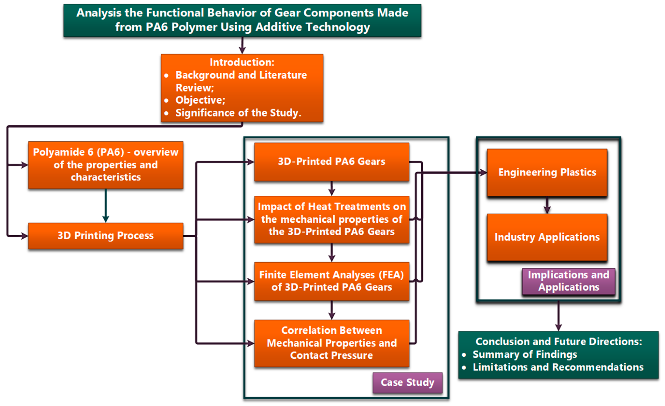
Figure 2.
The Raise E2 3D printer from the Additive Technologies Laboratory of the Mechanical and Electrical Engineering Faculty: (a) overview; (b) PA6 roll (Source: authors based on the research course).
Figure 2.
The Raise E2 3D printer from the Additive Technologies Laboratory of the Mechanical and Electrical Engineering Faculty: (a) overview; (b) PA6 roll (Source: authors based on the research course).
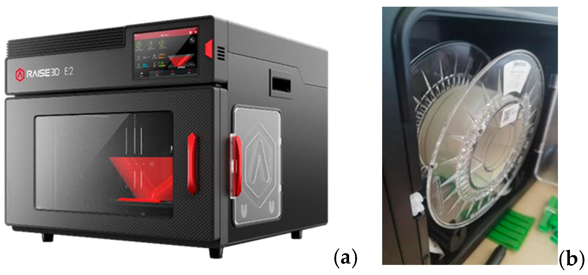
Figure 3.
Experimental setup for future tribological research: (a) experimental device for future tribological research; (b) PA6 gear (Source: authors based on the research course).
Figure 3.
Experimental setup for future tribological research: (a) experimental device for future tribological research; (b) PA6 gear (Source: authors based on the research course).
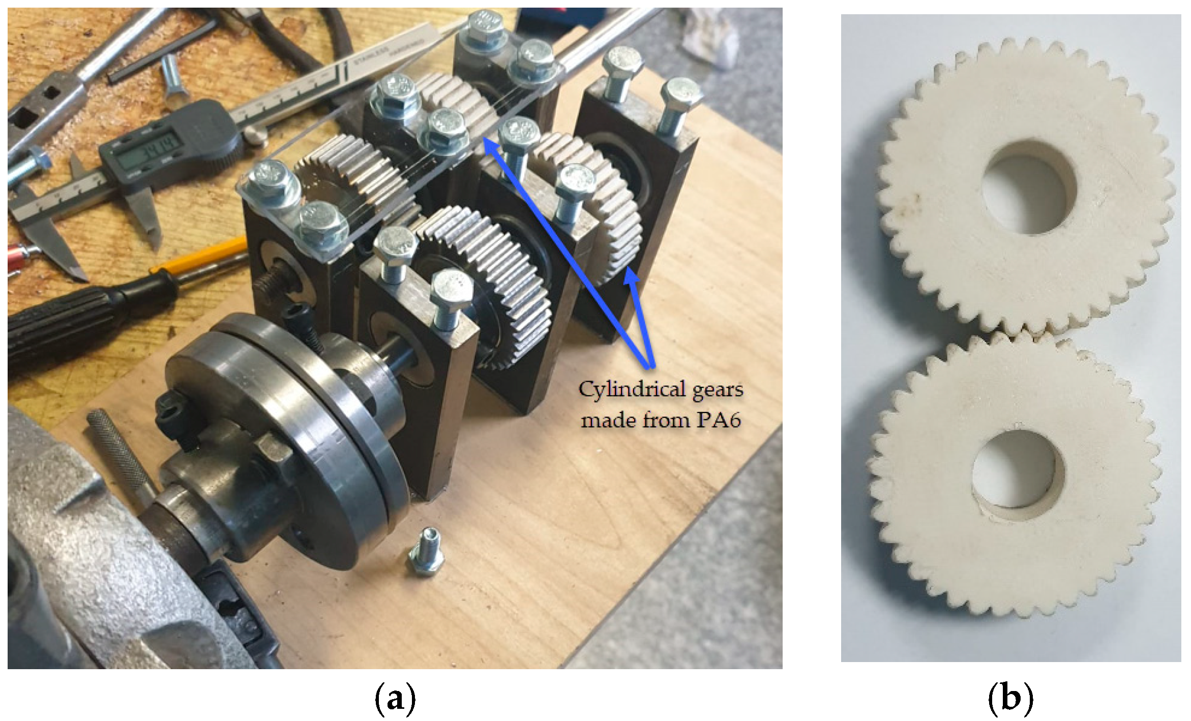
Figure 4.
The geometric properties of the gears were numerically analysed: (a) reference diameters; (b) corresponding dimensions of the teeth (Source: authors based on the case study).
Figure 4.
The geometric properties of the gears were numerically analysed: (a) reference diameters; (b) corresponding dimensions of the teeth (Source: authors based on the case study).
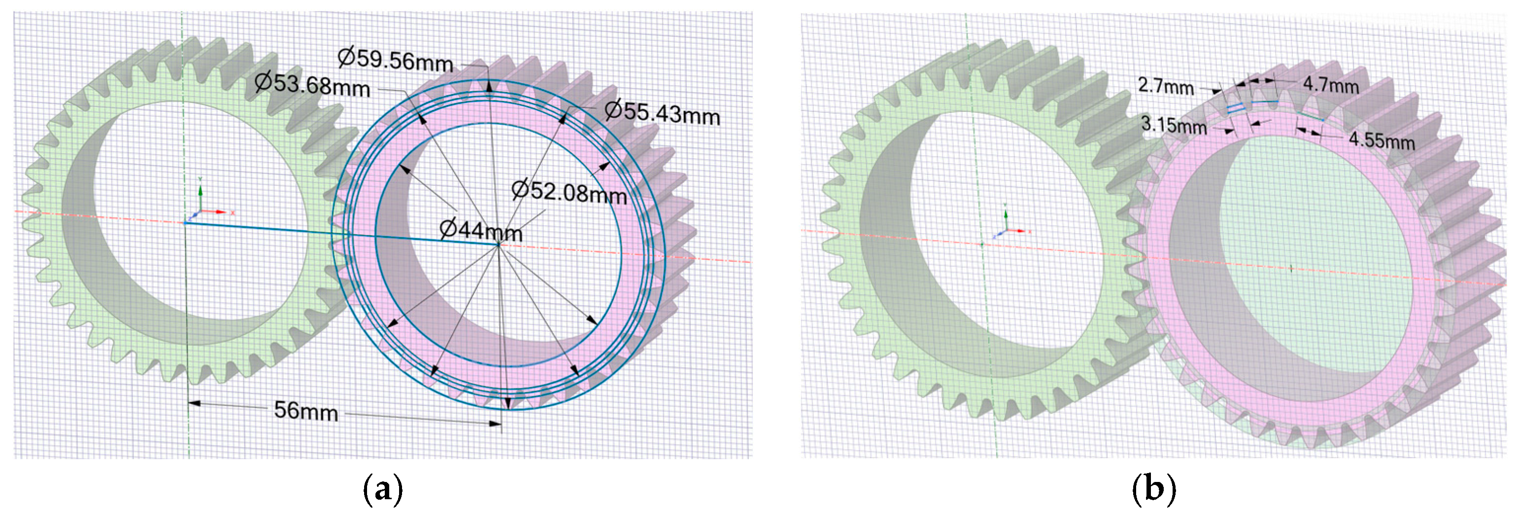
Figure 5.
Gear wheel notations, adapted from [20]: (a) reference diameters; (b) meshing elements (Source: authors based on the case study).
Figure 5.
Gear wheel notations, adapted from [20]: (a) reference diameters; (b) meshing elements (Source: authors based on the case study).
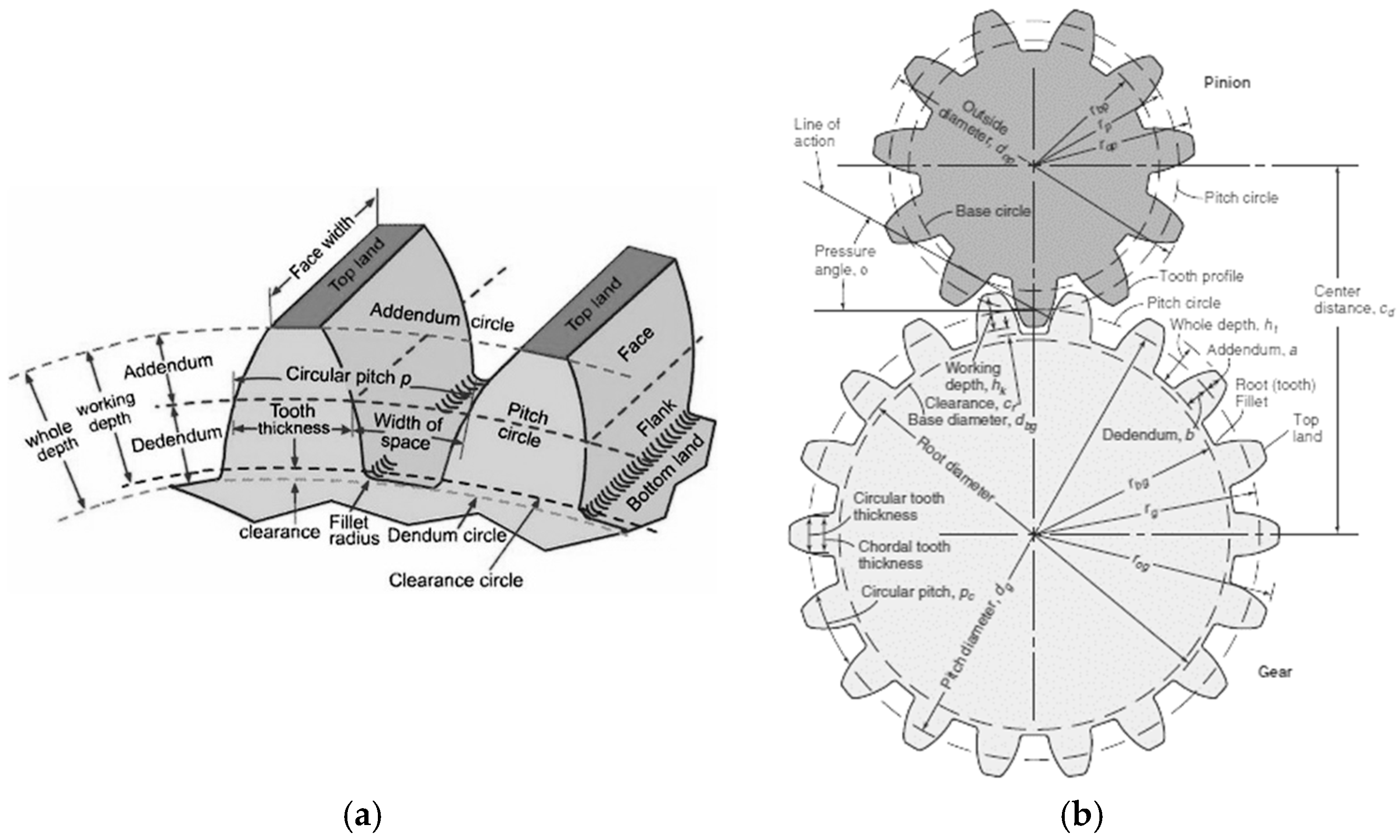
Figure 6.
The models for discretization that correspond to the sensitivity analysis in element size expressed, [mm]: (a) 0.25; (b) 0.22; (c) 0.18; (d) 0.1 (Source: authors based on the results of the sensitivity analysis).
Figure 6.
The models for discretization that correspond to the sensitivity analysis in element size expressed, [mm]: (a) 0.25; (b) 0.22; (c) 0.18; (d) 0.1 (Source: authors based on the results of the sensitivity analysis).
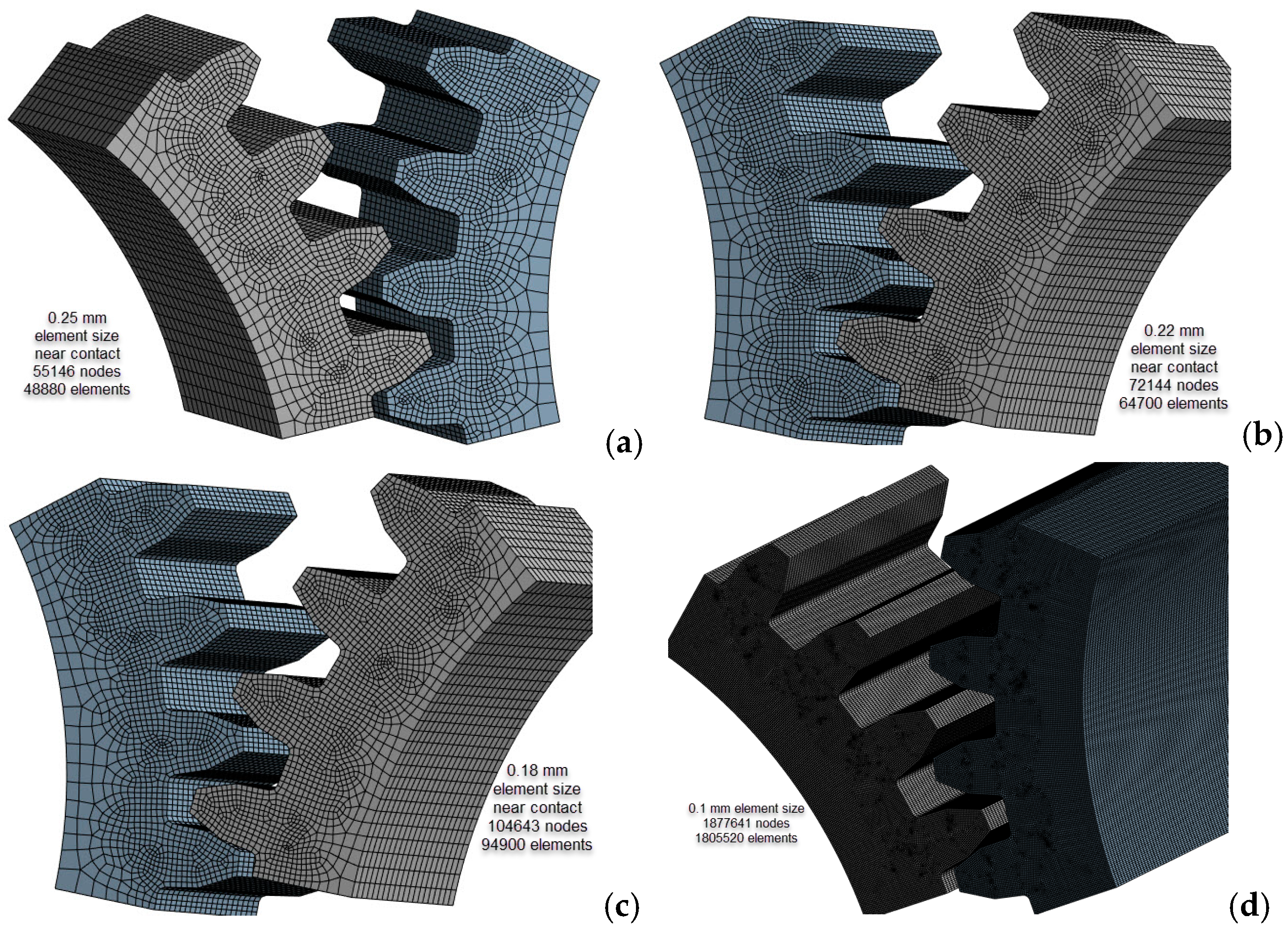
Figure 7.
The results of the sensitivity analysis (Source: authors based on the sensitivity analysis).
Figure 8.
The calculation scheme associated with classical beam theory (Source: authors based on the analysis results).
Figure 8.
The calculation scheme associated with classical beam theory (Source: authors based on the analysis results).
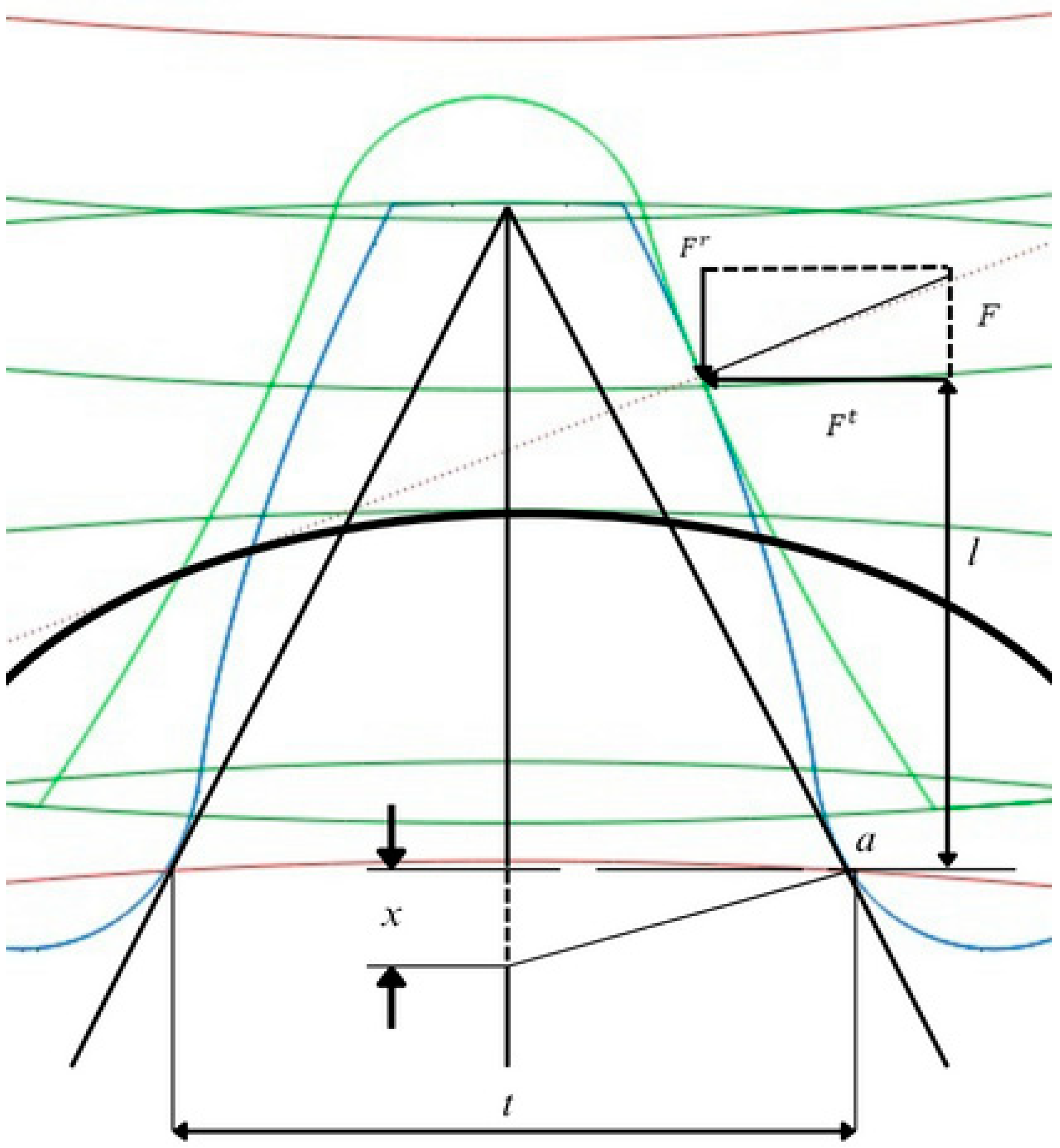
Figure 9.
Boundary conditions: (a) frictional surfaces; (b) revolute surfaces; (c) joint moment and rotation (Source: authors based on simulation results).
Figure 9.
Boundary conditions: (a) frictional surfaces; (b) revolute surfaces; (c) joint moment and rotation (Source: authors based on simulation results).
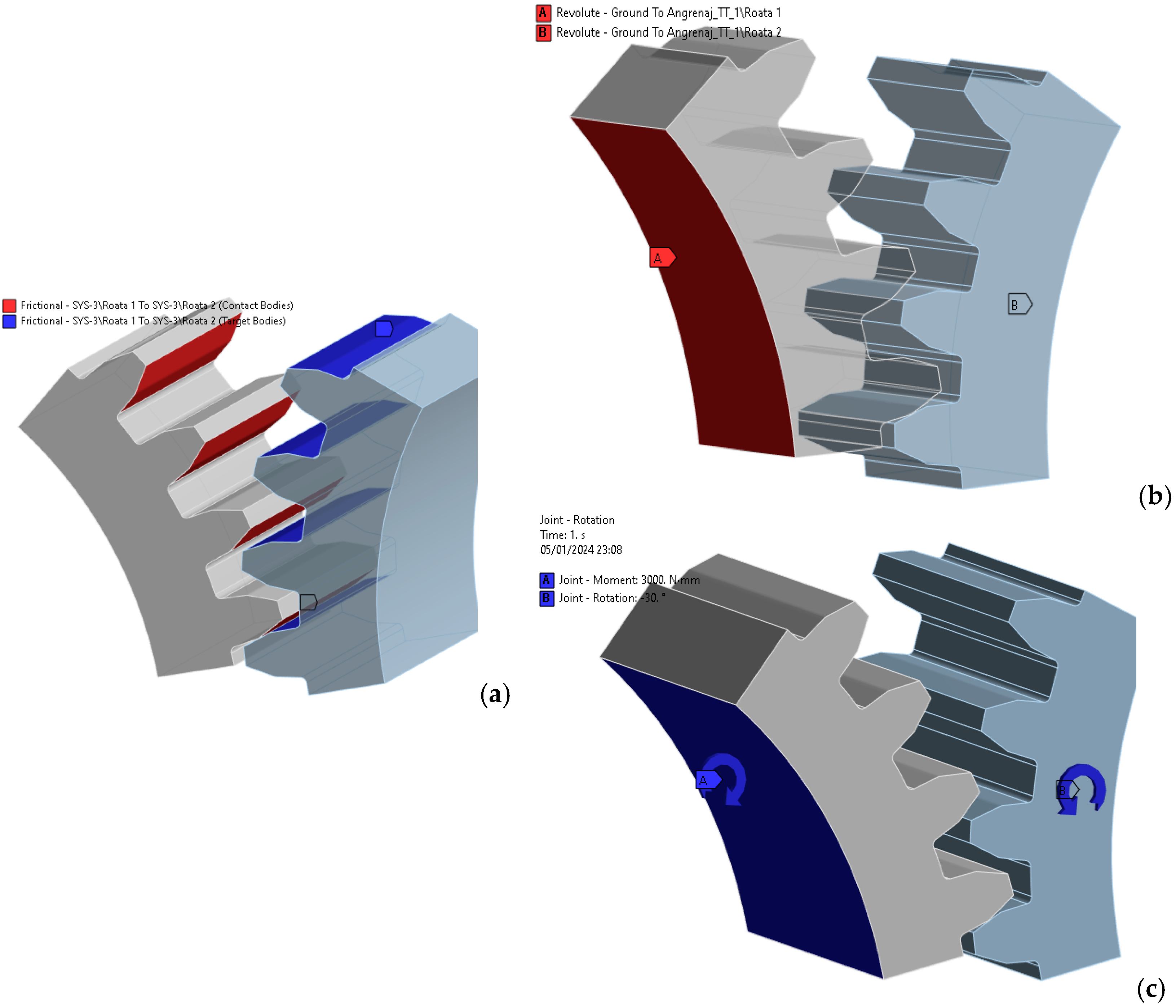
Figure 10.
Path line and bending stress (PA6 untreated): (a) stress on path line; (b) bending stress distribution, [MPa] (Source: authors based on the bending stress simulation results).
Figure 10.
Path line and bending stress (PA6 untreated): (a) stress on path line; (b) bending stress distribution, [MPa] (Source: authors based on the bending stress simulation results).
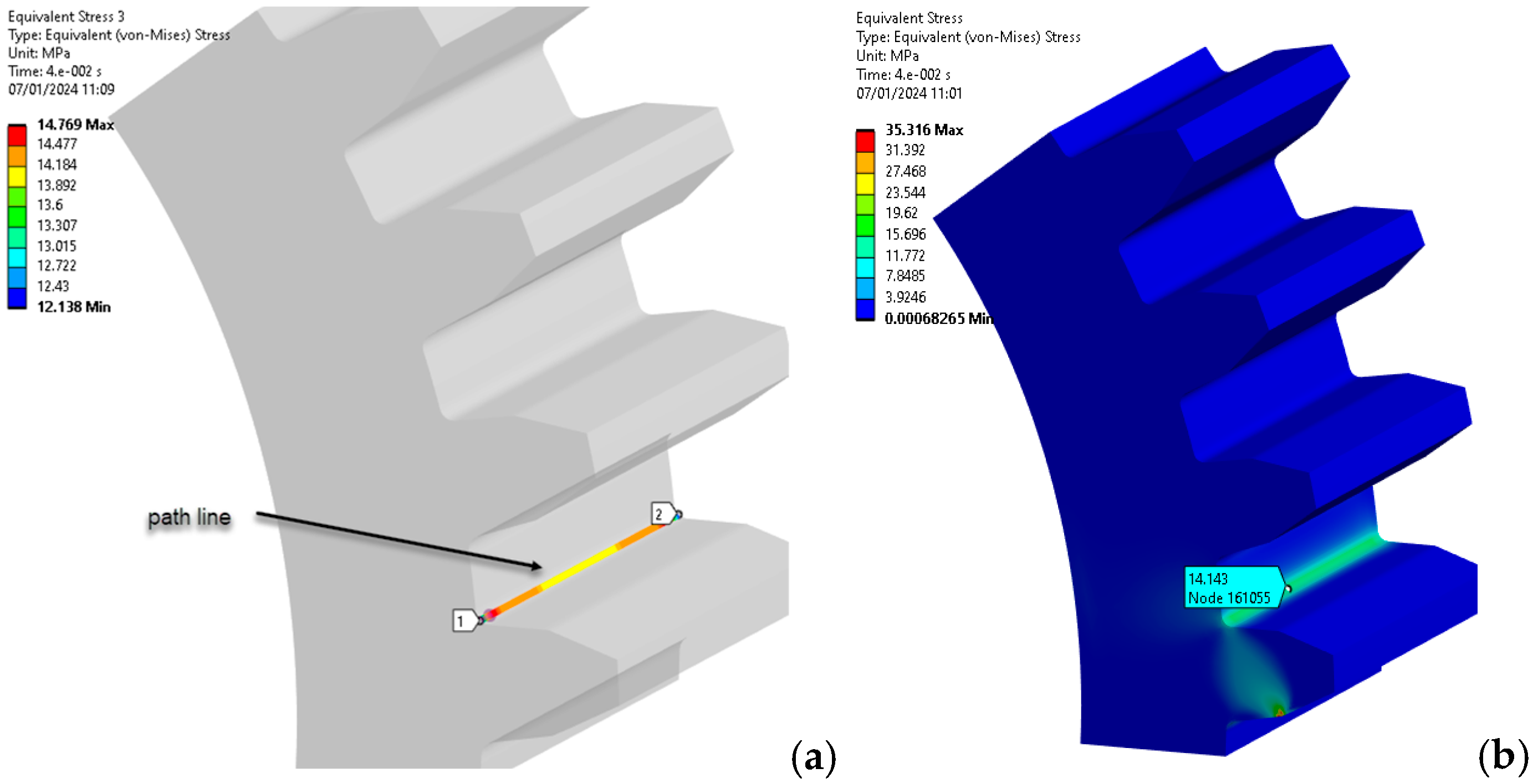
Figure 11.
Stresses in the contact zone (PA6 untreated) (Source: authors based on the bending stress simulation results).
Figure 11.
Stresses in the contact zone (PA6 untreated) (Source: authors based on the bending stress simulation results).
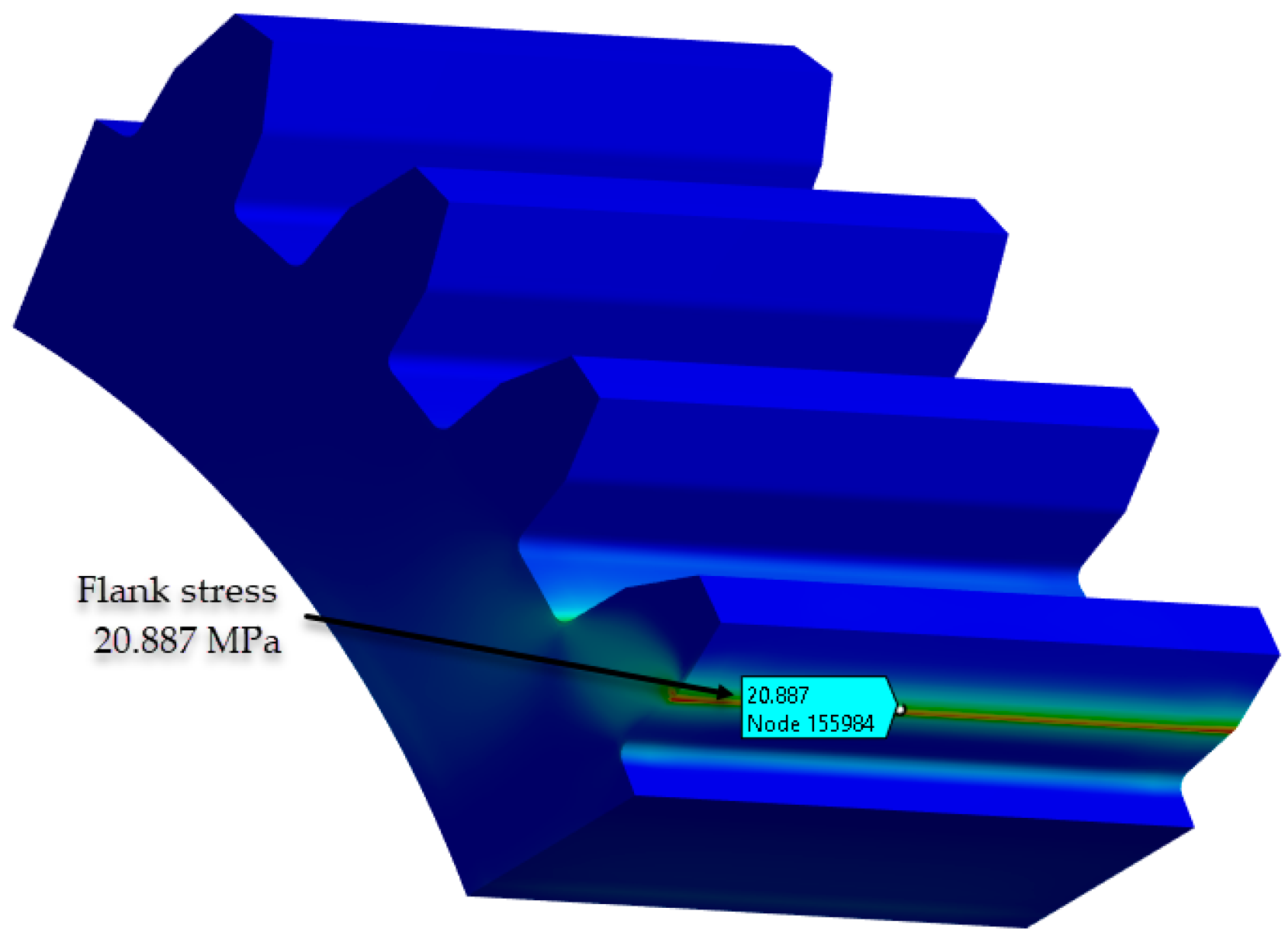
Figure 13.
Contact (hertzian) pressure PA6, non-treated: (a) non-iterative calculation VDI 2736-2, KISSsoft; (b) FEA-Ansys 2023 (Source: authors based on the simulation results).
Figure 13.
Contact (hertzian) pressure PA6, non-treated: (a) non-iterative calculation VDI 2736-2, KISSsoft; (b) FEA-Ansys 2023 (Source: authors based on the simulation results).
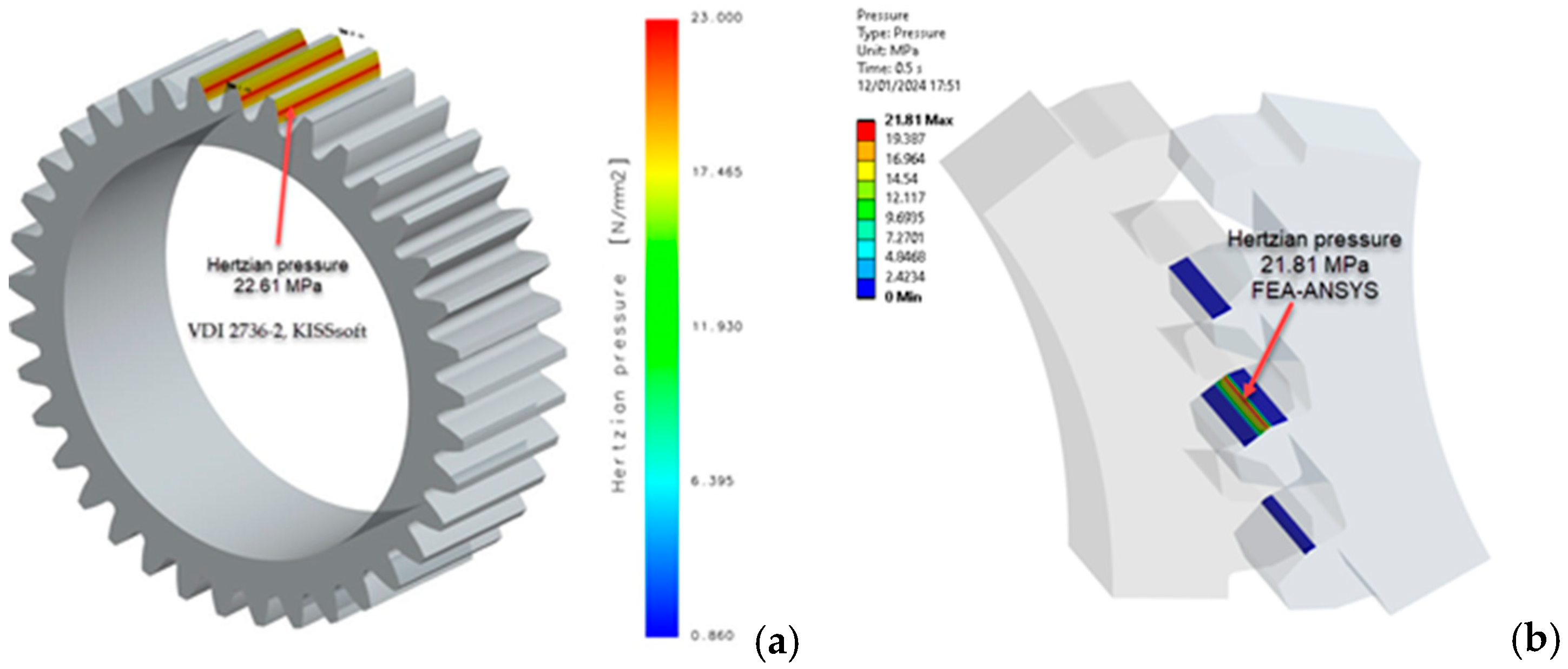
Figure 14.
Contact (hertzian) pressure PA6, head-treated (E=5,000 MPa): (a) non-iterative calculation VDI 2736-2, KISSsoft; (b) FEA-Ansys 2023 (Source: authors based on the simulation results).
Figure 14.
Contact (hertzian) pressure PA6, head-treated (E=5,000 MPa): (a) non-iterative calculation VDI 2736-2, KISSsoft; (b) FEA-Ansys 2023 (Source: authors based on the simulation results).
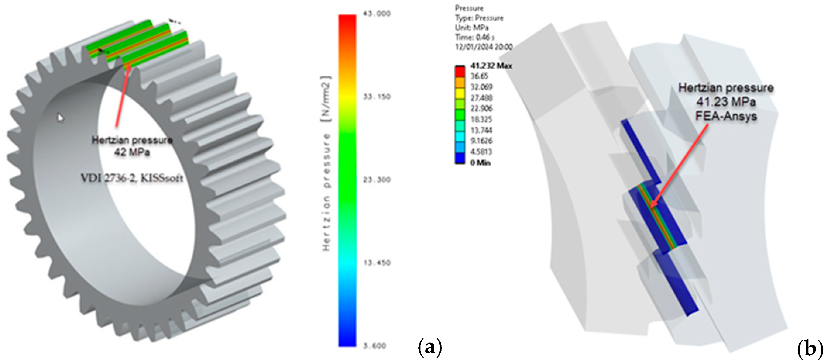
Figure 15.
Contact (hertzian) pressure PA6, head-treated (E=6,000 MPa): (a) non-iterative calculation VDI 2736-2, KISSsoft; (b) FEA-Ansys 2023 (Source: authors based on the simulation results).
Figure 15.
Contact (hertzian) pressure PA6, head-treated (E=6,000 MPa): (a) non-iterative calculation VDI 2736-2, KISSsoft; (b) FEA-Ansys 2023 (Source: authors based on the simulation results).
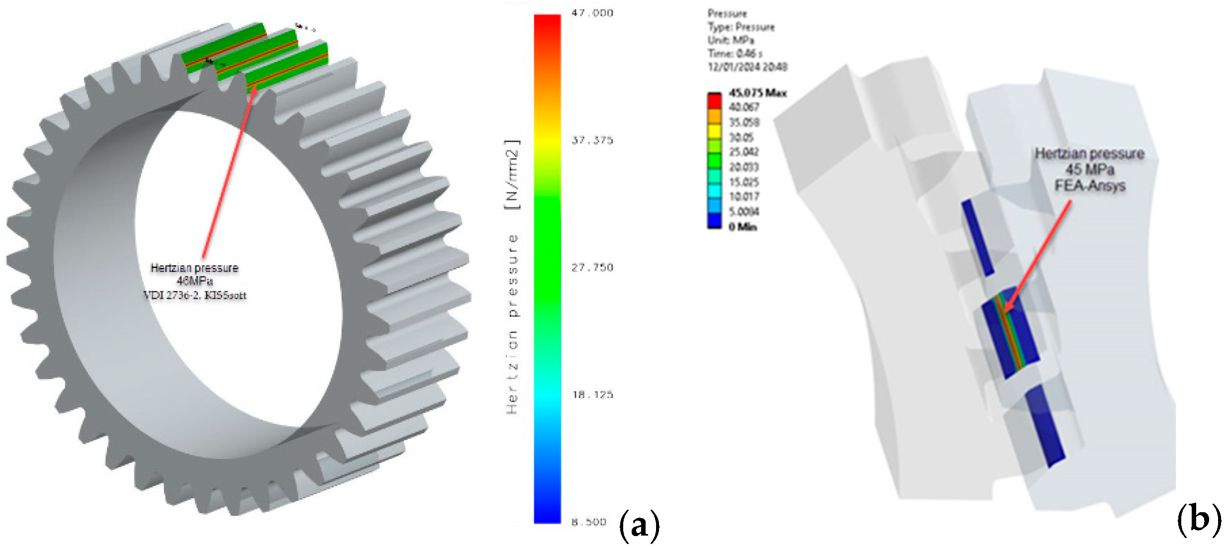
Figure 16.
Worn tooth flank distribution in case of PA6 (heat-treated) using non-iterative simulation (VDI 2736-2, KISSsoft) (Source: authors based on the simulation results).
Figure 16.
Worn tooth flank distribution in case of PA6 (heat-treated) using non-iterative simulation (VDI 2736-2, KISSsoft) (Source: authors based on the simulation results).
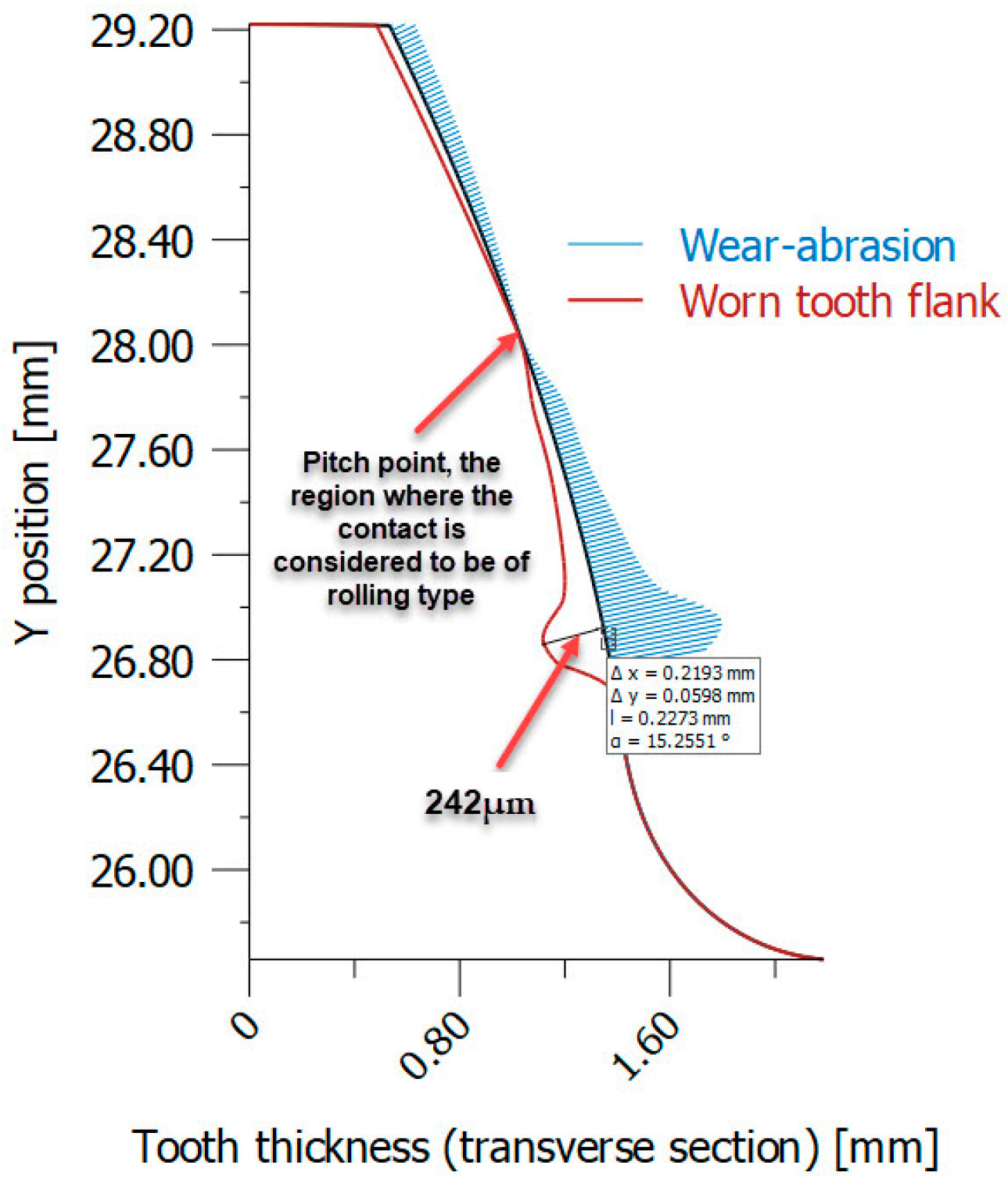
Figure 17.
Worn tooth flank distribution in case of PA6 (heat-treated) using iterative simulation (VDI 2736-2, KISSsoft): (a) PA6 not heat-treated (E = 2,100 MPa); (b) PA6 heat-treated (E = 5,000 MPa) (Source: authors based on the simulation results).
Figure 17.
Worn tooth flank distribution in case of PA6 (heat-treated) using iterative simulation (VDI 2736-2, KISSsoft): (a) PA6 not heat-treated (E = 2,100 MPa); (b) PA6 heat-treated (E = 5,000 MPa) (Source: authors based on the simulation results).
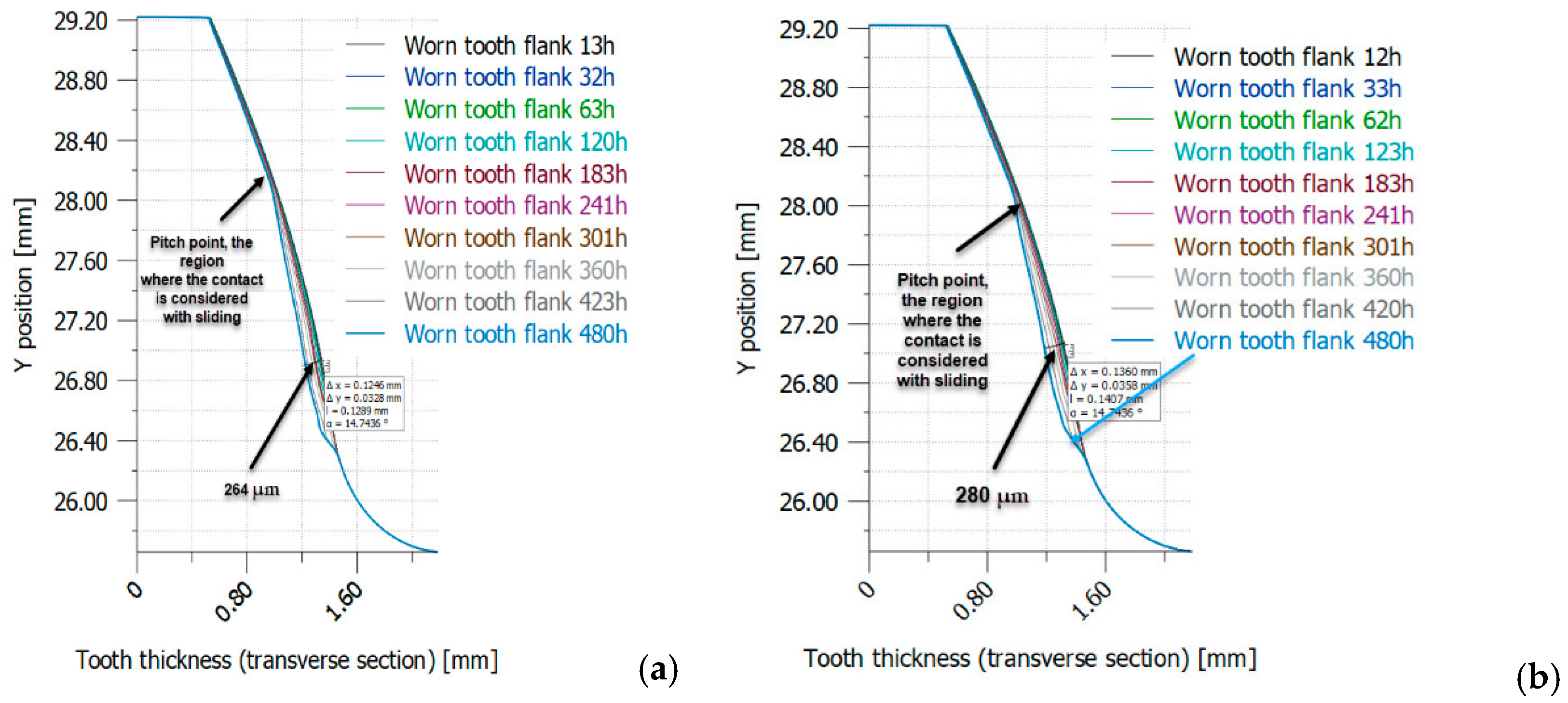
Figure 18.
Worn tooth flank distribution in case of PA6 (heat-treated) using iterative simulation (VDI 2736-2, KISSsoft): (a) PA6 heat-treated (E = 6,000 MPa); (b) PA6 heat-treated (E = 8,000 MPa) (Source: authors based on the simulation results).
Figure 18.
Worn tooth flank distribution in case of PA6 (heat-treated) using iterative simulation (VDI 2736-2, KISSsoft): (a) PA6 heat-treated (E = 6,000 MPa); (b) PA6 heat-treated (E = 8,000 MPa) (Source: authors based on the simulation results).
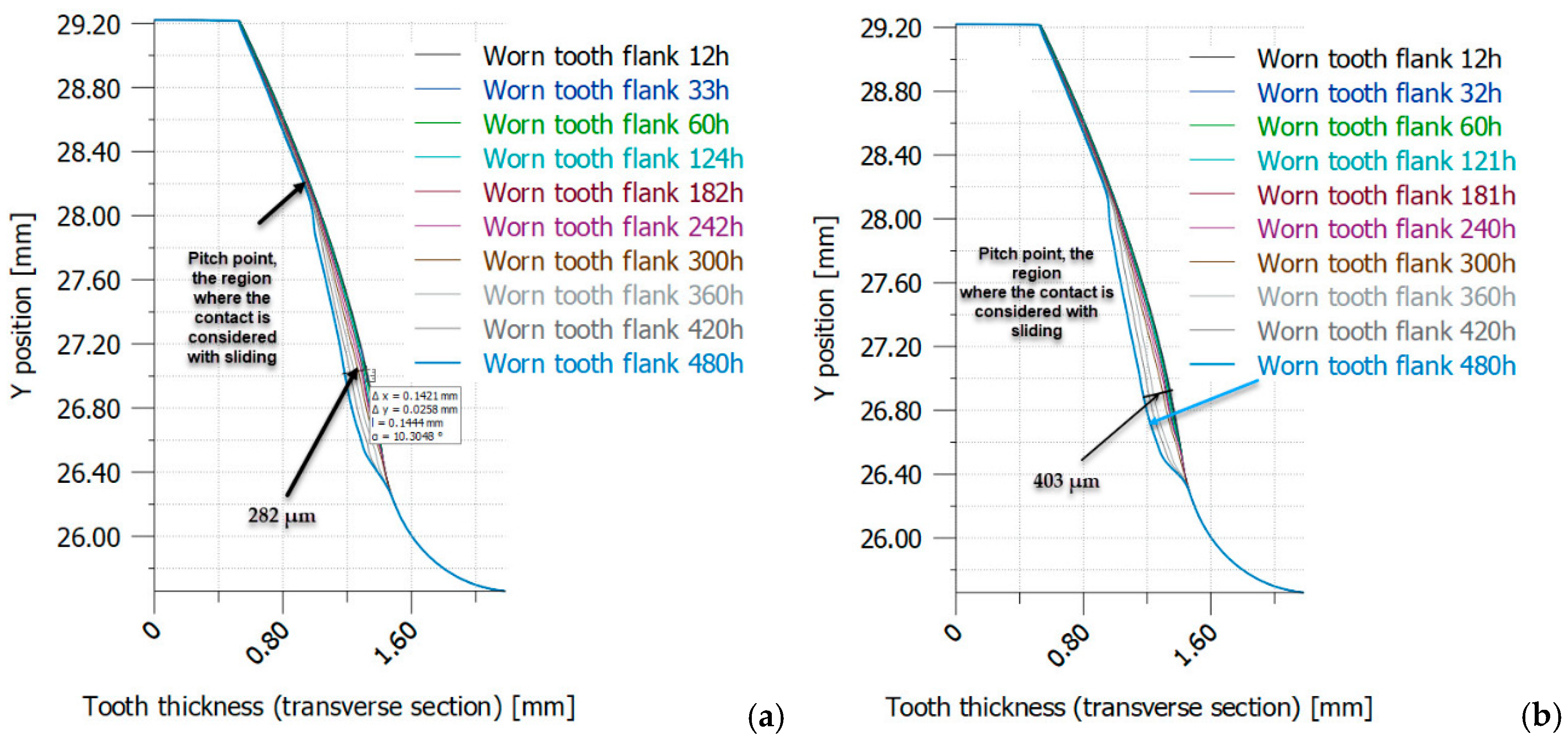

Table 1.
Additive printing parameters used to print PA6 gears – filament 3d printing manufacturer recommendation (Source: authors based on the research course).
Table 1.
Additive printing parameters used to print PA6 gears – filament 3d printing manufacturer recommendation (Source: authors based on the research course).
| Parameter | Value |
|---|---|
| Nozzle thickness | 0.8 mm |
| Print height layer | 0.2 mm |
| Temperature of deposition bed | 80 °C |
| Melt temperature | 260 °C |
| Percentage of filling | 100 % |
Table 2.
The geometric parameters of the PA6 polymer gear samples were tested (Source: authors based on the gear design).
Table 2.
The geometric parameters of the PA6 polymer gear samples were tested (Source: authors based on the gear design).
| Parameters | Values | |
|---|---|---|
| Number of teeth | [z] | 37 |
| Facewidth (mm) | [b] | 17 |
| Normal module (mm) | [m] | 1.5 |
| Normal pressure angle (°) | [α] | 20 |
| Material | Own Input | PA6 (VDI 2736) |
| Accuracy grade in accordance with ISO1328:2020 | A6 | |
| Reference diameter (mm) | [d] | 55.43 |
| Tip diameter (mm) | [da] | 59.56 |
| Root diameter (mm) | [df] | 52.08 |
| Addendum coefficient | [haP] | 1.00 |
| Dendum coefficient | [hfP] | 1.25 |
| Centre distance (mm) | [a] | 56 |
Table 3.
PA6 material properties involved in the FEA (Source: authors based on the test results).
| Parameters | Values | |
|---|---|---|
| Young's Modulus (in the scenario where the material is not heat-treated) |
[N/mm2] | 2,100÷2,800 [16,24] |
| Young's Modulus (in the scenario where the material is heat-treated) |
[N/mm2] | 6,000 |
| Poisson's Ratio | - | 0.4 [16] |
| Ultimate Tensile Strength (in the scenario where the material is not heat-treated) |
[N/mm2] | 48 [16,24] |
| Yield Strength (in the scenario where the material is not heat-treated) | [N/mm2] | 37 [16,24] |
| Ultimate Tensile Strength (in the scenario where the material is heat-treated, Tabel 16) |
[N/mm2] | 67 |
| Yield Strength (in the scenario where the material is heat-treated) | [N/mm2] | 58 |
| Density | [kg/m3] | 1,130 [9] |
| Wear factor | [mm3/Nm] | (7.8÷9) ·10-6 [18,19] |
Table 4.
Comparative results between the approached methods (FEA-analytical) (Source: authors based on the finite element analysis results).
Table 4.
Comparative results between the approached methods (FEA-analytical) (Source: authors based on the finite element analysis results).
| Bending stress [MPa] | ||||
|---|---|---|---|---|
| KISSsoft | Lewis Bending Equation | Classical beam theory | FEA | Finite element size [mm] |
| 14.65 Analytical base on VDI 2736 Part 2 [10] |
11.14 |
14.16 |
9.25 | 0.25 |
| 10.98 | 0.22 | |||
| 11.53 | 0.18 | |||
| 14.9 | 0.1 | |||
Table 5.
Bending stress evaluation according VDI 2736-2 [10,24,25] (Source: authors based on the bibliography).
| Stress type | Mathematical expression [10,25] | Coefficients used [10,25] |
Meaning of the coefficients [25] |
|---|---|---|---|
| Bending stress |
[MPa] |
- tooth root load factor - application factor - dynamic factor - face load factor - transverse load factor |
|
|
- nominal tangential load [N] T - nominal torque of pinion [Nmm] d - reference circle of pinion [mm] |
|||
|
- ooth form factor - normal module [mm] - pressure angle - normal pressure angle - bending moment arm relevant to load application at the tooth tip [mm] |
|||
|
- stress correction factor - notch factor - Tooth root chord at the critical section [mm] |
|||
|
- contact ratio - transverse contact ratio |
|||
|
- helix angle factor - overlap ratio - helix angle |
|||
| - stress correction factor | |||
| Permissible bending stress |
[MPa] |
- llowable stress on the tooth root [MPa] - the required minimum safety factor for continuous operation is generally = 2.0. - maximum root strength [MPa] |
|
| Allowable bending stress |
defined as stress level with 10% failure probability [25] |
- fatigue strength (nominal root stress) [MPa] [32] | |
| Service life factor |
combined into [25] |
- life factor |
Table 6.
Service life and bending stress calculation results (Source: authors based on the calculation results).
Table 6.
Service life and bending stress calculation results (Source: authors based on the calculation results).
| Method | H [hr] Service Life |
KA Application factor |
SF Safety for tooth root stress |
Nominal stress at tooth root (MPa) |
Tooth root stress (MPa) |
Permissible tooth root stress (MPa) |
|---|---|---|---|---|---|---|
| PA6 Untreated (E = 2,100 MPa) |
3024 | 1.25 | 4.83 | 11.72 | 14.65 (14.14 FEA) |
54.46 |
| PA6 160 °C annealing temperature (E = 6,000 MPa) |
3024 | 1.25 | 4.83 | 11.72 | 14.65 (14.31 FEA) |
54.46 |
Table 7.
Service life and flank stress calculation results (pitting) (Source: authors based on the calculation results).
Table 7.
Service life and flank stress calculation results (pitting) (Source: authors based on the calculation results).
| Method | H [hr] | SH Safety factor for contact stress on operating pitch circle |
σH0 Nominal contact stress (MPa) |
σH Contact stress at operating pitch circle (MPa) |
σHP Permissible contact stress (MPa) |
|---|---|---|---|---|---|
| PA6 Untreated (E = 2,100 MPa) |
3,024 | 1.46 | 20.46 | 22.87 (20.887 FEA) |
35.26 |
| PA6 120 °C annealing temperature (E = 4,000 MPa) |
3,024 | 1.06 | 28.23 | 31.57 | 35.26 |
| PA6 140 °C annealing temperature (E = 5,000 MPa) |
2,973 | 0.95 | 31.57 | 35.29 | 35.26 |
| PA6 160 °C annealing temperature (E = 6,000 MPa) |
1,024 | 0.87 | 34.58 | 38.66 | 35.26 |
Table 8.
Wear results for non-iterative calculation (VDI 2736-2, KISSsoft) (Source: authors based on the software results).
Table 8.
Wear results for non-iterative calculation (VDI 2736-2, KISSsoft) (Source: authors based on the software results).
| PA6 | Local linear wear (µm) |
Wear, volume per tooth (mm³) |
Wear, mass per gear (g) |
Hertzian pressure (N/mm²) |
|
|---|---|---|---|---|---|
| Min | Max | ||||
| PA6 - Untreated (E = 2,100 MPa) |
0.89 | 267 | 2.77 | 0.11 | 22.61 |
| PA6 - 120 °C annealing temperature (E = 4,000 MPa) |
0.90 | 251 | 2.66 | 0.11 | 42 |
| PA6 - 140 °C annealing temperature (E = 5,000 MPa) |
0.90 | 242 | 2.6 | 0.11 | 46 |
| PA6 - 160 °C annealing temperature (E = 6,000 MPa) |
0.90 | 231 | 2.53 | 0.11 | 54 |
Table 9.
Wear results for iterative calculation (VDI 2736-2, KISSsoft) (Source: authors based on the software results).
Table 9.
Wear results for iterative calculation (VDI 2736-2, KISSsoft) (Source: authors based on the software results).
| PA6 | Local linear wear (µm) |
Wear, volume per tooth (mm³) |
Wear, mass per gear (g) |
|---|---|---|---|
| PA6 - Untreated (E = 2,100 MPa) |
264 | 3.93 | 0.164 |
| PA6 - 120 °C annealing temperature (E = 4,000 MPa) |
280.74 | 4.48 | 0.187 |
| PA6 - 140 °C annealing temperature (E = 5,000 MPa) |
271 | 4.54 | 0.19 |
| PA6 - 160 °C annealing temperature (E = 6,000 MPa) |
403 | 5.95 | 0.25 |
Table 10.
The validation of numerical analyses (regarding material loss due to wear) presented through the comparison of percentage differences relative to experimental simulations.
Table 10.
The validation of numerical analyses (regarding material loss due to wear) presented through the comparison of percentage differences relative to experimental simulations.
| PA6 | Wear, mass per gear -iterative calculation (g) |
Wear, mass per gear-experminetal calculaion (g) |
Percentage difference (%) |
|---|---|---|---|
| PA6 - Untreated (E = 2,100 MPa) |
0.164 | 0.141 | 4.17 |
| PA6 - 120 °C annealing temperature (E = 4,000 MPa) |
0.187 | 0.194 | 3.67 |
| PA6 - 140 °C annealing temperature (E = 5,000 MPa) |
0.19 | 0.197 | 3.61 |
| PA6 - 160 °C annealing temperature (E = 6,000 MPa) |
0.25 | 0.258 | 3.14 |
Table 11.
Minimum values required for fatigue strength under pulsating stress (nominal stress) and rolling contact fatigue strength, which must be achieved through heat treatments applied to PA6 (Source: authors based on the test results).
Table 11.
Minimum values required for fatigue strength under pulsating stress (nominal stress) and rolling contact fatigue strength, which must be achieved through heat treatments applied to PA6 (Source: authors based on the test results).
| Fatigue strength type |
PA6 Non-treated (E = 2,100 MPa) (retrieved from the KISSsoft database) |
PA6 Treated 120 °C annealing temperature |
PA6 Treated 160 °C annealing temperature |
|||
|---|---|---|---|---|---|---|
| 600 h | 3,000 h | 600 h | 3,000 h | 600 h | 3,000 h | |
| Fatigue strength under pulsating stress (nominal stress) [MPa] | 43.4 | 35.4 | 44 | 38 | 48 | 43 |
| Rolling contact fatigue strength [MPa] |
41.9 | 33.5 | 44 | 38 | 48 | 43 |
Disclaimer/Publisher’s Note: The statements, opinions and data contained in all publications are solely those of the individual author(s) and contributor(s) and not of MDPI and/or the editor(s). MDPI and/or the editor(s) disclaim responsibility for any injury to people or property resulting from any ideas, methods, instructions or products referred to in the content. |
© 2024 by the authors. Licensee MDPI, Basel, Switzerland. This article is an open access article distributed under the terms and conditions of the Creative Commons Attribution (CC BY) license (http://creativecommons.org/licenses/by/4.0/).
Copyright: This open access article is published under a Creative Commons CC BY 4.0 license, which permit the free download, distribution, and reuse, provided that the author and preprint are cited in any reuse.


