

Submitted:
13 August 2024
Posted:
13 August 2024
You are already at the latest version
Abstract
The awareness of the vulnerability of existing structures under both seismic and energy viewpoints highlight the need to develop integrated retrofit solutions combining the structural and thermal performances. In this perspective, the study explores the efficacy of the Resisto 5.9 Tube system, a seismic coat that improves the seismic behaviour of masonry and reinforced concrete (RC) structures, also enhancing their energy performances, thanks to the thermal coat integrated in the basic steel system. The research involves the application of a design procedure specifically developed for this retrofit system from the seismic perspective. Once all the system elements are designed, non-linear static analyses are performed with a Finite Element software comparing the building’s seismic performances before and after the application of Resisto 5.9 Tube. The results demonstrate a significant increase in seismic safety coefficient, proving that this intervention type can be useful to obtain the seismic upgrading of existing RC buildings.
Keywords:
Integrated retrofit
; Steel exoskeletons
; Existing buildings
; Reinforced Concrete structures
; Design method
; Pushover analyses
1. Introduction
In recent years, there has been increasing recognition of the need to enhance seismic performance and energy efficiency in existing buildings, driven by the impact of recent seismic events and climate change [1]. Reinforced concrete buildings constitute a significant portion of the Italian building stock, particularly those constructed during the post-war period without seismic considerations. These buildings share common characteristics that make them highly vulnerable to seismic activity [2]. The current research focuses on a multi-story residential building located in northern Italy, constructed in the late 1970s with reinforced concrete (RC) frames in one direction only and hollow brick infill walls. This configuration is particularly susceptible to seismic forces [3,4]. The RC structure was selected as a case study to evaluate the effectiveness of Resisto 5.9 Tube, developed by the company Progetto Sisma Srl. This recent solution for integrated retrofitting combines seismic reinforcement with energy efficiency improvements. The so-called seismic energy coat integrates various technologies for seismic retrofit [5,6] and energy requalification using insulating panels. Resisto 5.9 Tube features a cold-formed steel exoskeleton for seismic resistance, combined with external thermal insulation panels [7]. The application from building outside is a great advantage, as it minimizes disruption to occupants and preserves the interior activities during installation phases. The system was investigated under the seismic viewpoint by means of Finite Element Analysis (FEA) with the Pro_Sap software. Before implementing the reinforcement in the calculation software, it was designed according to a procedure specifically developed for Resisto 5.9 Tube aiming at defining the thickness of the bracing elements at each building level to optimize the performances of the existing structure to be retrofitted. Finally, non-linear static analyses were carried out to compare the structural behaviour before and after retrofitting phases, with a focus on the variation in seismic safety coefficient and seismic risk class according to the Italian regulations.
2. Materials and Methods
The case study is a multi-story residential building located in Rozzano, in the province of Milan in Italy. The city of Rozzano is in the northern part of Italy in a low seismicity area with a Peak Ground Acceleration (PGA) of 0.075 g and in a climatic zone E, characterized by 2404 Degree-Days (Figure 1).
In this context, enhancing the building's structural performance is most effective when coupled with improvements in thermal behaviour. Resisto 5.9 Tube, developed by the Italian company Progetto Sisma Srl, is a retrofit solution designed to simultaneously enhance both seismic resilience and energy efficiency in existing masonry and reinforced concrete structures. This system can be customized to address the specific needs of each structure, utilizing a design method tailored for this lightweight exoskeleton made of cold-formed steel profiles. The current research aims to evaluate the effectiveness of this design approach for seismic retrofitting of a real RC structure. Seismic performance is assessed through nonlinear static analysis performed using a Finite Element software, comparing the structural behaviour before and after the application of the retrofit technique.
2.1. Existing RC Building
The building under investigation is a multi-story reinforced concrete (RC) structure constructed in the late 1970s. It features a commercial ground floor and three additional upper levels used for residential purposes. The building's plan is rectangular, measuring approximately 40 meters by 13 meters. The structure comprises RC frames oriented solely in one direction (longitudinal direction X), interconnected by the slabs, perimeter beams, and two stair and elevator cores (see Figure 2).
The building is characterized by hollow brick infill walls with large openings, especially in the longitudinal facades and at the ground level, as shown in Figure 3.
The information about the building is gathered through an experimental campaign conducted both on-site and in laboratories. This campaign aimed to assess the geometrical configuration, loading conditions, and mechanical properties of the structural materials, which are then compared with the existing documentation for the building. In accordance with Italian standards [8,9], a normal level of knowledge (KL2) is achieved, corresponding to a confidence factor (FC) of 1.2 for reducing resistance values.
The RC columns have rectangular cross-sections of varying dimensions (30x30 cm, 30x40 cm, and 30x50 cm), with longitudinal bars and stirrups φ8/30. The RC beams, which are dropped, also have rectangular cross-sections, with dimensions of 30x50 cm and 30x60 cm, and use stirrups φ8/20. All structural elements are constructed with concrete of class C25/30 and are reinforced with B450C steel, as detailed in Table 1 and Table 2, respectively.
2.2. Cold-Formed Exoskeleton
The system under investigation is the Resisto 5.9 Tube, developed by Progetto Sisma Srl. This innovative solution, known as a seismic-energy coat, is designed for the integrated retrofitting of existing masonry and reinforced concrete buildings. The seismic-resistant component of the system consists of a cold-formed steel exoskeleton, featuring a braced frame that is securely connected to the existing RC columns and beams using chemical anchors. This exoskeleton is installed externally, parallel to the building's façades, allowing normal activities within the building to be continued during the assembly process.
The steel frame is constructed from horizontal and vertical members, both of which have hollow rectangular cross-sections with a thickness of 2 mm, but with varying dimensions. The horizontal members, measuring 60x25 mm, are inserted into the holes of the vertical members, which measure 60x45 mm (Figure 4a). The components of the steel frame are connected using gusset plates and bolts, which also serve to attach the diagonal bracings to the frame and to secure the attachment to the RC structure (Figure 4b). The diagonal bracings are fastened to the gusset plates with steel rivets, and they have a width of 50 mm, while their thickness is determined by the design specifications (Figure 4c).
The elements of the exoskeleton are designed with modular holes, allowing for a standardized configuration. The standard module features a spacing of 1 meter between the horizontal and vertical members, though different dimensions can be used to tailor the retrofit solution to the specific requirements of the structure being reinforced. The reinforcement process is completed with the addition of insulating panels and finishing layers. The final configuration of the system seismic-resistant part is illustrated in Figure 5.
The elements of the Resisto 5.9 Tube system—including the horizontal and vertical members, as well as the diagonal bracings—are constructed from pre-galvanized steel of type S320GD+Z. The anchoring bolts used in the system have a diameter of 12 mm and are of resistance class 8.8. The mechanical properties of the structural materials are summarized in Table 3 for the steel elements and in Table 4 for the connectors.
Finally, the improvement in the building's thermal performance is achieved using expanded polystyrene insulating panels, which are applied at the intended thickness and covered with various types of finishing materials.
2.3. Retrofitted RC Building
Before implementing the design procedure and conducting seismic analysis on the reinforced structure, it is essential to define the geometric configuration of the reinforcement system. The cold-formed exoskeleton is applied across the entire structure, taking into account architectural constraints such as openings and balconies. Wherever possible, the standard module, with a 1-meter spacing between horizontal and vertical members, is utilized. The system is anchored to the ground via a reinforced concrete (RC) foundation beam, to which the steel vertical members are securely attached. This new foundation is connected to the existing one using grouted bars. The dimensions of the steel elements correspond to those specified in the standard solution, with the exception of the diagonal bracing thickness, which is calculated using the design procedure to optimize reinforcement effectiveness. The schematic configuration of the Resisto 5.9 Tube system is illustrated in Figure 6.
2.4. Finite Element Modelling and Analysis
The seismic analysis is conducted using Pro_Sap, a software developed by the Italian company 2S.I. Software e Servizi per L’Ingegneria S.r.l. The case study building is modeled in the software both before and after the installation of the Resisto 5.9 Tube system, to assess its contribution to the seismic upgrading of the existing RC structure. The structure is evaluated through nonlinear static analyses, and the seismic safety factor is calculated in accordance with the Italian code. The RC members are modelled as bidimensional elements with nonlinear properties, using a concentrated plasticity model with assigned values for the plastic hinges' capacity. Notably, the infill walls are not included in the structural model; instead, they are represented as a uniform load distributed along the perimeter beams. Vertical loads are applied to the floors at each level, as specified in Table 5. The permanent loads on the top floor also included the weight of the roof, which is not directly incorporated into the calculation software. The floors are modeled as rigid slabs with a membrane thickness of 4 cm.
To compute the seismic loads for the nonlinear static analyses, the foundation soil category (C) and the topographic category (T1) are assigned. The type of action is calculated at the Ultimate Limit State (ULS) with different accidental eccentricities (positive, negative, and none) for each principal direction (longitudinal X and transverse Y). Two force distributions are considered: a triangular distribution, similar to that used in linear static analysis, and a mass-proportional distribution. The solid view of the model of the existing structure, as implemented in the Pro_Sap software, is shown in Figure 7.
The same loading conditions are applied to the retrofitted model, which is equivalent to the unreinforced structure, but equipped with the cold-formed exoskeleton. The steel elements are incorporated into the structural model as closely as possible to the actual configuration, with some necessary simplifications. The horizontal and vertical profiles are modeled as beam elements with moment releases to accurately represent the system’s constraint conditions. The diagonal bracings are modeled as nonlinear trusses, capable of sustaining only tensile stresses. The connections between the horizontal and vertical members and the RC structure are represented by rigid links, simulating the presence of the chemical anchors. The solid view of the retrofitted structure model, as implemented in the Pro_Sap software, is shown in Figure 8.
3. Results and Discussion
The unreinforced and reinforced RC residential buildings are subjected to nonlinear static analysis using the finite element software ProSap. The comparison of the results is conducted by examining the capacity curves of the structures and the seismic safety coefficients, as evaluated in accordance with the Italian Technical Standard. The following sections provide a summary of the key results from the numerical analysis, along with the outcomes of the design procedure.
3.1. Seismic Analysis on the Existing RC Building
The performance of the numerical analysis on the unreinforced building is crucial not only for assessing seismic safety and identifying vulnerabilities, but also for designing the cold-formed exoskeleton tailored to the building’s capacity and specific needs. The RC building is subjected to pushover analysis in both primary directions, generating capacity curves for each direction. Figure 9 presents the pushover curves under the most severe loading conditions for each thrust direction. The red square on the curves marks the point at which the first structural damage occurs, which is a key parameter for seismic design.
The main parameters of the analysis are summarized in Table 6, highlighting that the structure exhibits greater ductility in the transverse direction (Y) and increased stiffness and strength in the longitudinal direction (X). The initial damage in the structure occurs in the longitudinal direction at a displacement of 0.61 cm, whereas in the transverse direction, the first damage corresponds to a displacement of 1.75 cm.
3.2. Seismic Design of the Cold-Formed Exoskeleton
The first instance of damage serves as the starting point for the design method, which aims to determine the thickness of the diagonal members to optimize the retrofitting solution. This initial damage is observed in the longitudinal direction at a displacement of 0.61 cm. The design method, based on literature approaches [11,12] and adapted for this specific exoskeleton type [13], begins with the assumption that the retrofitted structure should exhibit ductility comparable to that of the unreinforced structure.
The process starts by setting a target displacement slightly lower than the displacement at first damage, which is fixed at 0.55 cm. Using the equivalent bilinear curve representation of the structure and the elastic spectrum in the Acceleration Displacement Response Spectrum (ADRS) format, an iterative procedure defines the ultimate displacement of the retrofitted structure and, consequently, its stiffness. This iterative process continues until the ductility of the retrofitted structure matches that of the unreinforced one.
At the end of the procedure, an equivalent bilinear curve representative of the cold-formed exoskeleton is derived by subtracting the design parameters of the retrofitted structure from those of the existing structure. According to the procedure, the design stiffness of the Resisto 5.9 Tube is determined to be 1.039.603 daN/cm. This value represents the total stiffness of the exoskeleton in the longitudinal direction and must be redistributed across each level and module of the Resisto 5.9 Tube. The distribution of stiffness along the building height is achieved using a proportionality factor, rk, which relates the overall stiffness of the existing structure to that of the Resisto 5.9 Tube. This factor is then applied to the floor stiffnesses of the existing structure to determine the floor stiffnesses of the exoskeleton, as detailed in Table 7.
To evaluate the regularity in height of the existing structure and determine whether the exoskeleton is needed to redistribute and homogenize the floor stiffnesses, reference to the Italian Code is made. According to the code, for a structure to be considered regular in height, the stiffness of successive floors should fall within the following range:
The existing buildings meet the requirements for regularity in height; therefore, it is not necessary to use the exoskeleton for redistributing stiffnesses.
To simplify the design procedure, the floor stiffness is divided by the number of exoskeleton modules in each direction (nRi) to determine the stiffness of a single diagonal (kRi,s). The design area of the diagonal (Ai) can then be computed using the following equation:
where Li is the average length of diagonal members, E is the elasticity modulus of the material, α is the inclination angle of diagonal members. Knowing the width of the diagonal members (bi), the design thickness (ti) for each level can be readily computed. Table 8 summarizes the results for one of the longitudinal façades, which represents the most severe condition.
Ultimately, it is decided to use the same diagonal member thickness of 1 mm for all levels, except for the first level, where a thicker member (2 mm) is required due to the large number of openings.
3.3. Seismic Analysis on the Retrofitted RC Building
The numerical analysis of the reinforced building aims to evaluate the effectiveness of the designed retrofitting system in enhancing seismic safety and reducing structural vulnerabilities. After installing the Resisto 5.9 Tube, the retrofitted RC building is subjected to pushover analysis to derive the capacity curves. Figure 10 illustrates these curves under the most severe loading conditions for each direction. In these curves, the red square indicates the point where the first damage occurs in the structure reinforced with the cold-formed exoskeleton.
The main parameters of the analysis are summarized in Table 9, highlighting that the overall behaviour of the retrofitted structure remains similar to that of the existing one, with increased ductility in the transverse direction (Y) and enhanced stiffness and strength in the longitudinal direction (X). Even after installing the exoskeleton, the first damage in the structure still occurs in the longitudinal direction.
3.4. Comparison of the Results
The comparison of the capacity curves for the structure before and after the application of Resisto 5.9 Tube (Figure 11) demonstrates how the cold-formed exoskeleton has improved the stiffness, ductility, and strength of the existing RC buildings. The percentage variations in the key parameters of the seismic analysis, both before and after the retrofit, are summarized in Table 10.
The efficacy of Resisto 5.9 Tube for the seismic upgrading of existing RC buildings is assessed by comparing the seismic safety index ζE before and after the retrofit intervention. The seismic safety index is evaluated according to the Italian Technical Standard as ratio between capacity and demand in terms of Peak Ground Acceleration, as reported in Equation (1):
This index represents the ratio between the seismic action that the building can sustain and the one that is requested for a new structure. To classify a retrofit intervention as seismic upgrading, the code requires that the seismic safety index must increase of at least 0.1. The cold-formed exoskeleton allows to achieve an increase of ζE value of 0.26 and, therefore, the seismic upgrading of the RC building is attained, as summarized in Table 11.
Finally, a comparison is made in terms of seismic risk classification according to the Italian Guidelines [14]. The seismic risk class of a building is determined based on two main parameters: the seismic safety index (IS−V) and the PAM value, which represents the expected annual loss. Each parameter is assigned a risk class ranging from A+ to G, with increasing levels of risk. The seismic risk of the building is classified according to the lower class.
4. Conclusions
The research focused on applying a cold-formed exoskeleton, known as Resisto 5.9 Tube, to a reinforced concrete (RC) structure for seismic-energy retrofitting. The system was initially designed using a procedure that determined the required thickness of the seismic-resistant bracings based on the specific needs of the structure. Due to large openings on the ground floor that limited the application of the exoskeleton, the design specified a bracing thickness of 2 mm for the first level and 1 mm for the upper levels. The effectiveness of the design was evaluated through nonlinear static analysis of the structure both before and after the system application. The results demonstrated that the exoskeleton significantly enhanced the seismic performance of the existing RC buildings. Specifically, the seismic safety index improved from 0.26 to 0.42, surpassing the minimum required increase of 0.1 as stipulated by the Italian Technical Standard for seismic upgrading. Additionally, the application of Resisto 5.9 Tube resulted in a reduction of seismic risk, advancing the seismic risk class from F to E.The ongoing research aims to further assess the system’s efficacy, including its performance in the presence of infill walls, which were only represented as a uniform load on the perimeter beams in this study. Despite the challenges posed by large openings, the positive impact of Resisto 5.9 Tube on the case study was confirmed, demonstrating its effectiveness in improving seismic resilience even when considering complex geometrical configurations.
Author Contributions
Conceptualization, A.F.; methodology, A.F.; software, E.M..; validation, A.F. formal analysis, E.M.; investigation, E.M., A.F.; resources, A.F.; data curation, E.M.; writing—original draft preparation, E.M.; writing—review and editing, A.F.; visualization, A.F.; supervision, A.F.; project administration, A.F.; funding acquisition, A.F.. All authors have read and agreed to the published version of the manuscript.
Funding
This research received no external funding.
Institutional Review Board Statement
Not applicable.
Informed Consent Statement
Not applicable.
Data Availability Statement
Data will be available upon request.
Acknowledgments
The Authors acknowledge the Progetto Sisma Srl company, who patented the Resisto 5.9 system and stipulated a research contract with the Department of Structures for Engineering and Architecture of the University of Naples Federico II (scientific responsible A. Formisano) to evaluate the system efficacy for retrofitting RC buildings. Also, the DPC-ReLUIS research project, where the current research activity is framed, is gratefully acknowledged. Finally, sincere thanks are also due to 2S.I. Software e Servizi per L’Ingegneria S.r.l., which provided the PRO_SAP software for conducting the numerical analyses.
Conflicts of Interest
The authors declare no conflicts of interest.
References
- Besen, P.; Boarin, P. Integrating energy retrofit with seismic upgrades to future-proof built heritage: Case studies of unreinforced masonry buildings in Aotearoa New Zealand. Building and Environment 2023, 241, 110512. [CrossRef]
- Clementi, F.; Quagliarini, E.; Maracchini, G.; Lenci, S. Post-War War II Italian school buildings: Typical and specific seismic vulnerabilities. Journal of Building Engineering 2015, 4, 152-166. [CrossRef]
- Valente, M.; Milani, G. Alternative retrofitting strategies to prevent the failure of an under-designed reinforced concrete frame. Engineering Failure Analysis 2018, 89, 271-285. [CrossRef]
- Braga, F.; Manfredi, V.; Masi, A.; Salvatori, A.; Vona, M. Performance of non-structural elements in RC buildings during the L’Aquila, 2009 earthquake. Bulletin of Earthquake Engineering 2011, 9(1), 307-324. [CrossRef]
- Pohoryles, D.A.; Bournas, D.A.; Da Porto, F.; Caprino, A.; Santarsiero, G.; Triantafillou. Integrated seismic and energy retrofitting of existing buildings: A state-of-the-art review. Journal of Building Engineering 2022, 61, 105274. [CrossRef]
- Meglio, E.; Longobardi, G.; Formisano, A. Integrated seismic-energy retrofit systems for preventing failure of a historical RC school building: Comparison among metal lightweight exoskeleton solutions. Engineering Failure Analysis 2023, 154, 107663. [CrossRef]
- Progetto Sisma. Available online: https://www.progettosisma.it/ (accessed on 29/07/2024).
- Ministry of Infrastructure and Transport. Technical Standards for Construction. In Official Gazette; Number 42 of 20 February 2018; Ministry of Infrastructure and Transport: Rome, Italy, 2018. (In Italian).
- Ministry of Infrastructure and Transport. Instructions for the Application of the New Technical Code for Constructions. In Official Gazette; Number 7 of 21 February 2019; Ministry of Infrastructure and Transport: Rome, Italy, 2019. (In Italian).
- Resisto 5.9 Tube, Progetto Sisma. Available online: https://www.progettosisma.it/wp-content/uploads/2024/04/Resisto_5.9_Tube_ITA.pdf (accessed on 29/07/2024).
- Ponzo, F.C.; Di Cesare, A.; Arleo, G.; Totaro, P. Seismic protection of existing buildings with hysteretic dissipative bracing: Design and execution aspects. Seismic Design, LediJournals 2010, 1, 37-60.
- Fajfar, P.; Gašperšič P. The N2 method for the seismic damage analysis of buildings. Earthquake Engineering & Structural Dynamics 1996, 25, 31-46.
- Meglio, E.; Davino, A.; Formisano, A. Design Method of Lightweight Steel Exoskeletons for Seismic-Energy Upgrading of Existing RC Buildings. In Proceedings of the 11th International Conference on Behaviour of Steel Structures in Seismic Areas, Salerno, Italy, 8-10 July 2024.
- Coordinated text of Ministerial Decree No. 58 of 28/02/2017 and subsequent amendments and additions (Ministerial Decree No. 65 of 07/03/2017 and Ministerial Decree No. 24 of 09/01/2020 “Guidelines for the Classification of Seismic Risk of Constructions”.
Figure 1.
Localization of the case study in the Italian territory (a), seismic hazard map (b) and climate zones map (c). .
Figure 1.
Localization of the case study in the Italian territory (a), seismic hazard map (b) and climate zones map (c). .
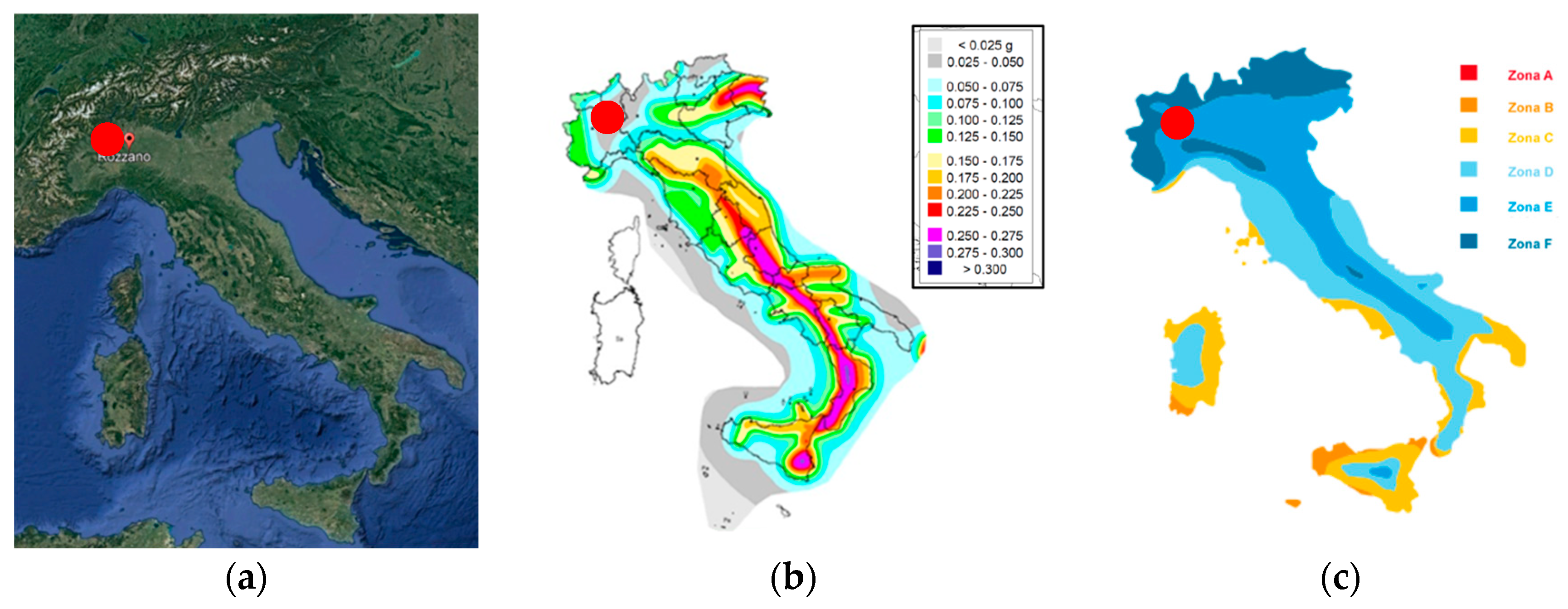
Figure 2.
Architectural (a) and structural (b) plan layouts of the case study building.
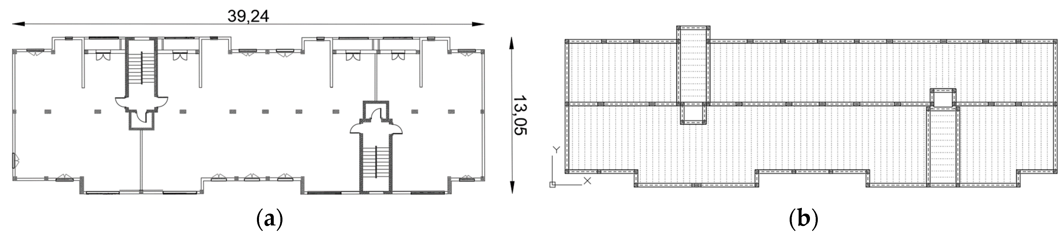
Figure 3.
Longitudinal (a) and transversal (b) façades of the case study.
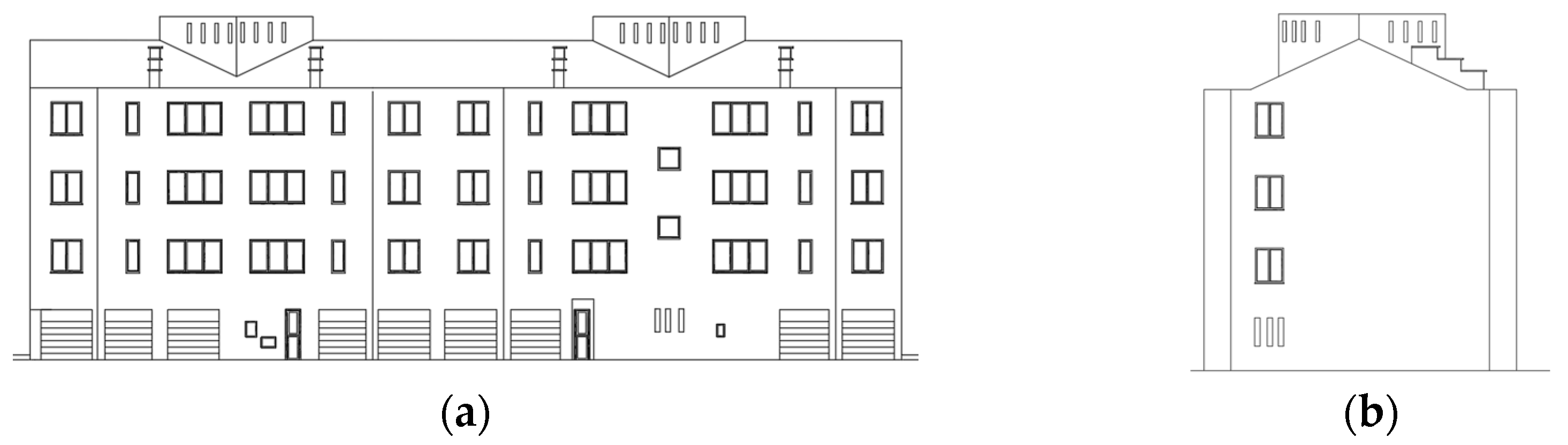
Figure 4.
Elements of Resisto 5.9 Tube: horizontal and vertical members (a), connections (b) and diagonal bracings (c) [10].
Figure 4.
Elements of Resisto 5.9 Tube: horizontal and vertical members (a), connections (b) and diagonal bracings (c) [10].
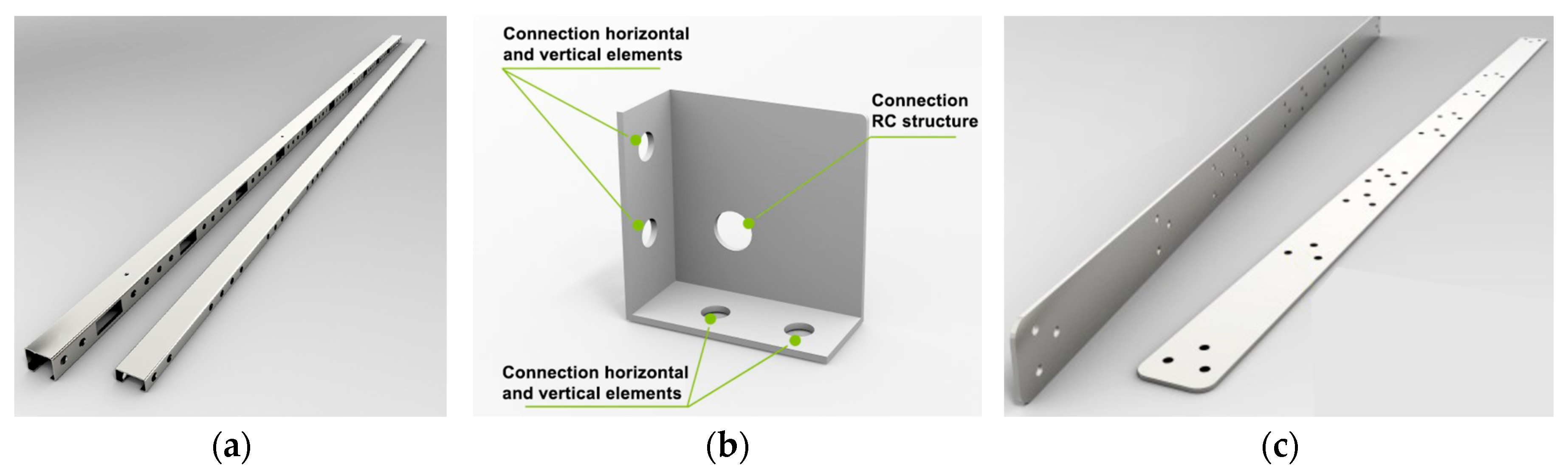
Figure 5.
Standard configuration of Resisto 5.9 Tube: detail of the connections (a) and RC structure equipped with the seismic-resistant braced frame (b) [10].
Figure 5.
Standard configuration of Resisto 5.9 Tube: detail of the connections (a) and RC structure equipped with the seismic-resistant braced frame (b) [10].
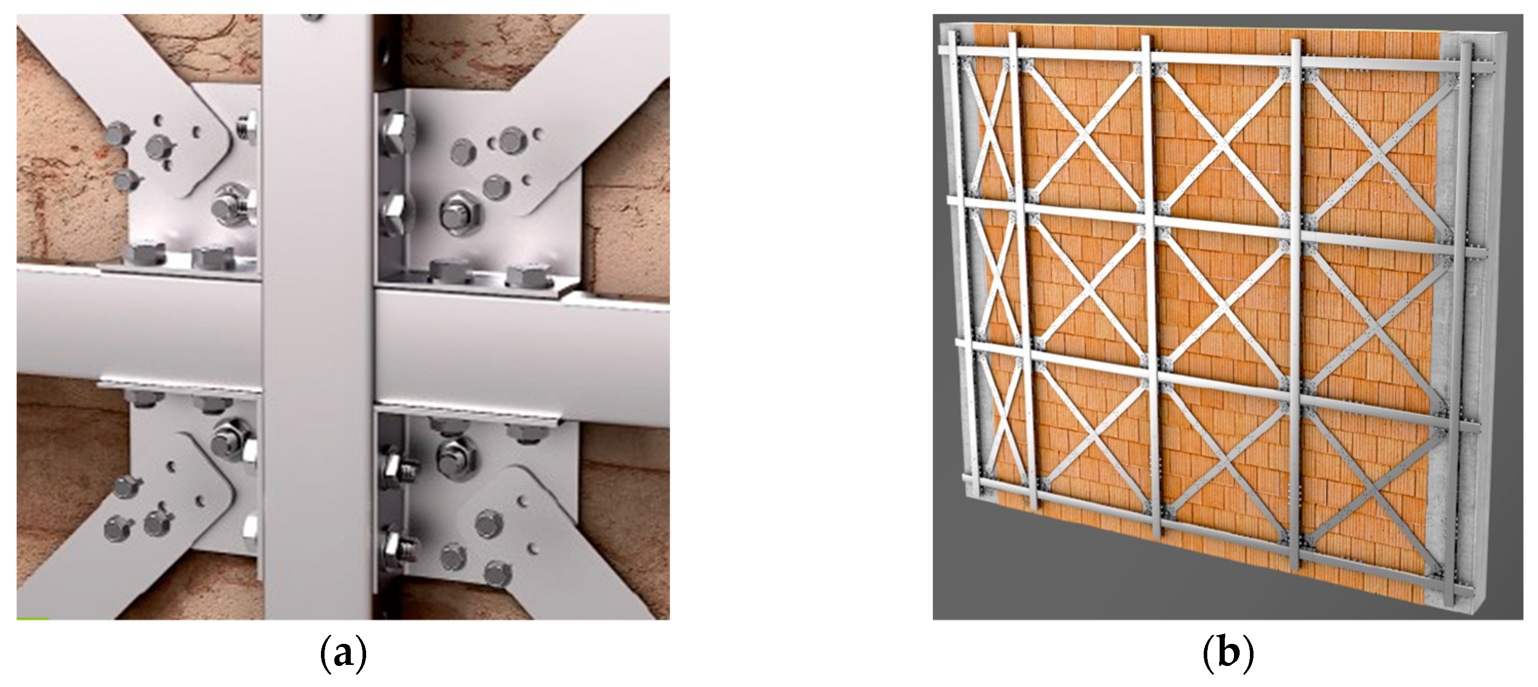
Figure 6.
Schematic configuration of the reinforcement: longitudinal (a) and transversal (b) façades of the retrofitted building.
Figure 6.
Schematic configuration of the reinforcement: longitudinal (a) and transversal (b) façades of the retrofitted building.
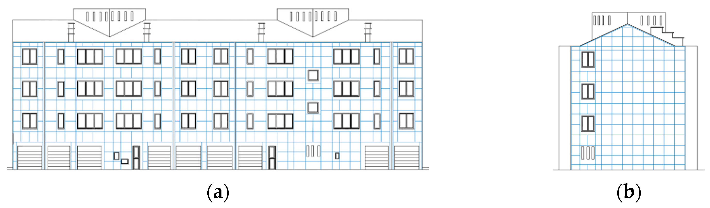
Figure 7.
FEM model of the existing structure: 3D view (a), plan layout (b), longitudinal sections (c, e) and transversal sections (d, f).
Figure 7.
FEM model of the existing structure: 3D view (a), plan layout (b), longitudinal sections (c, e) and transversal sections (d, f).
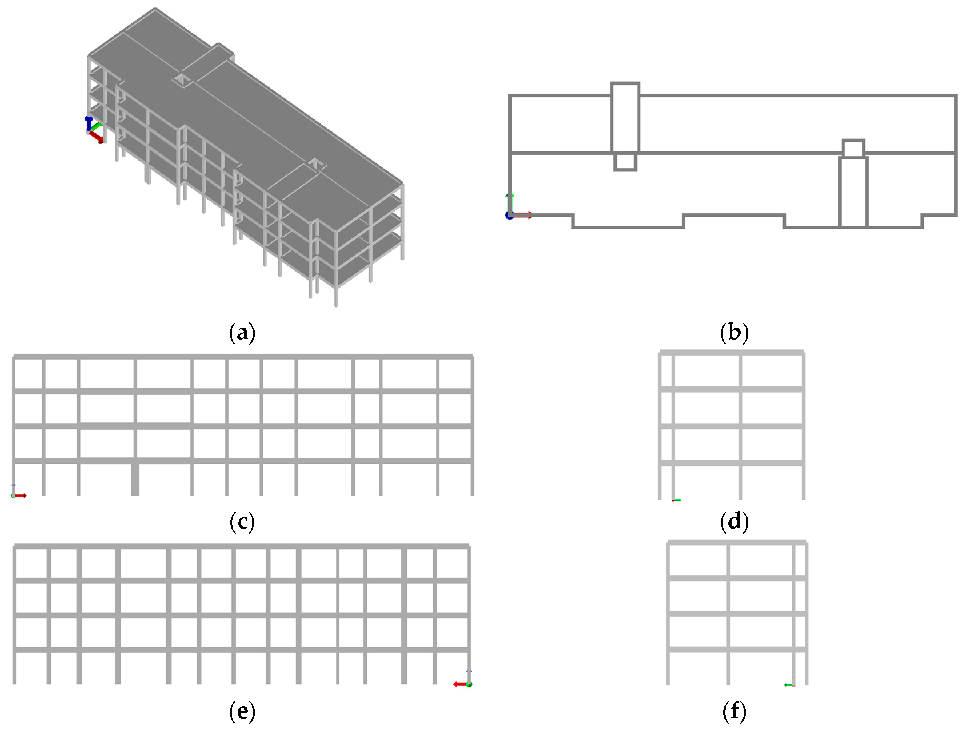
Figure 8.
FEM model of the retrofitted structure: 3D view (a), plan layout (b), longitudinal sections (c, e) and transversal sections (d, f).
Figure 8.
FEM model of the retrofitted structure: 3D view (a), plan layout (b), longitudinal sections (c, e) and transversal sections (d, f).
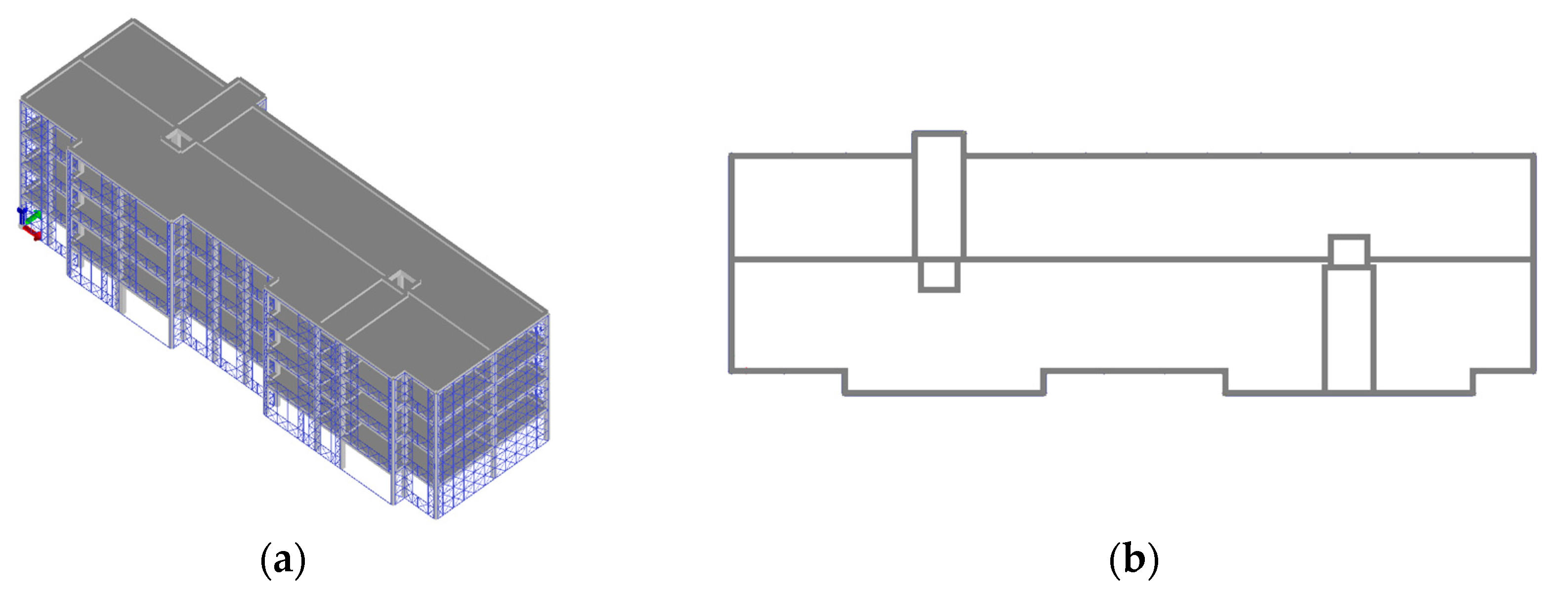
Figure 9.
Capacity of the existing structure in the most severe condition: pushover curves (a), individuation of the first damage (b).
Figure 9.
Capacity of the existing structure in the most severe condition: pushover curves (a), individuation of the first damage (b).
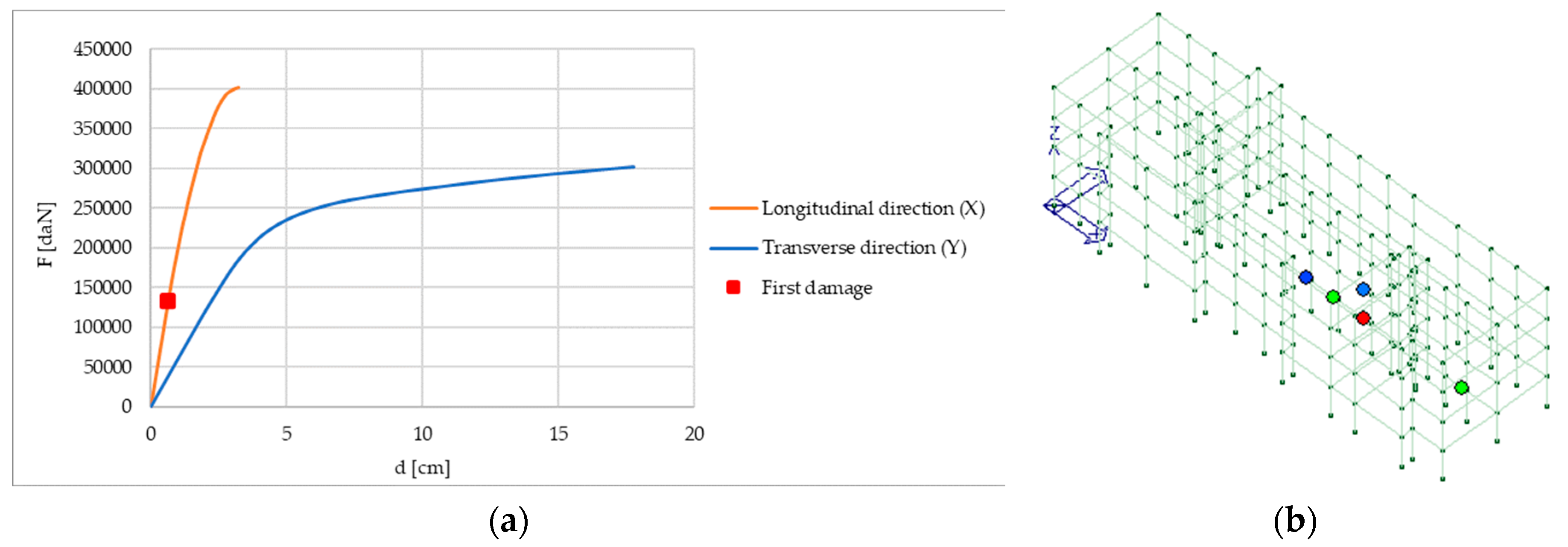
Figure 10.
Capacity of the retrofitted structure in the most severe condition: pushover curves (a) and individuation of the first damage (b).
Figure 10.
Capacity of the retrofitted structure in the most severe condition: pushover curves (a) and individuation of the first damage (b).
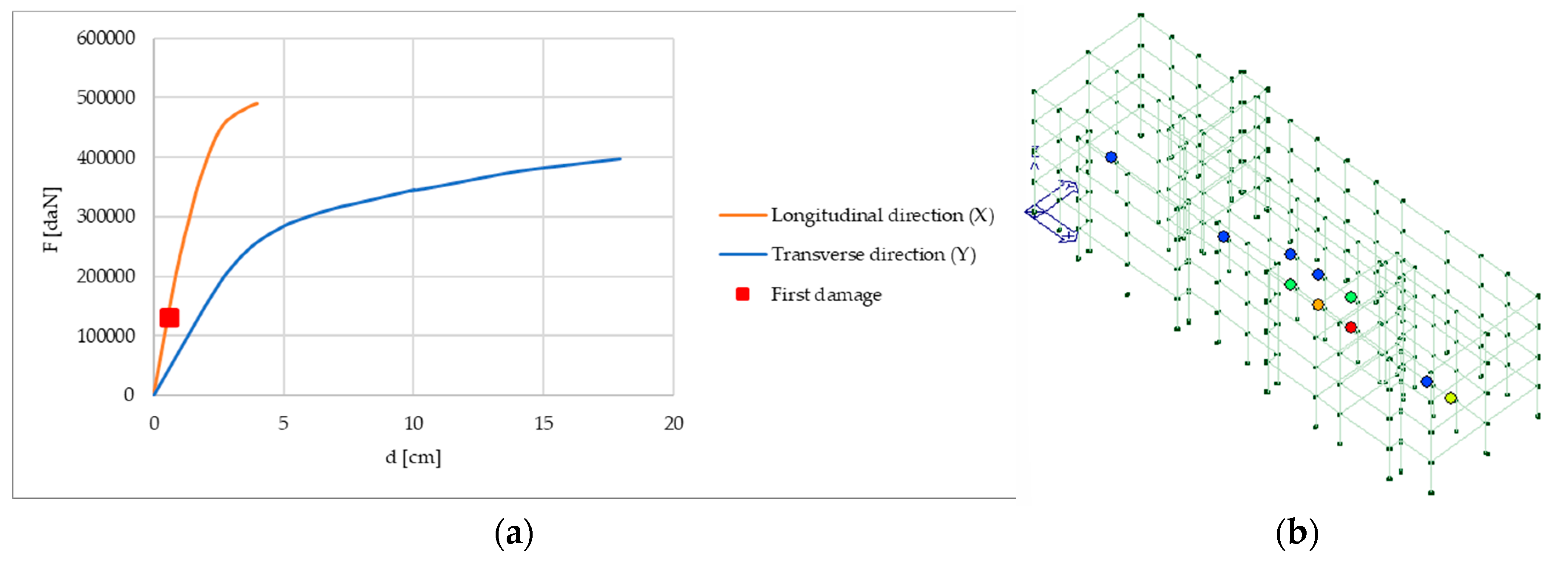
Figure 11.
Comparison of capacity of the existing and retrofitted structures in the most severe condition: longitudinal direction X (a) and transverse direction Y (b).
Figure 11.
Comparison of capacity of the existing and retrofitted structures in the most severe condition: longitudinal direction X (a) and transverse direction Y (b).
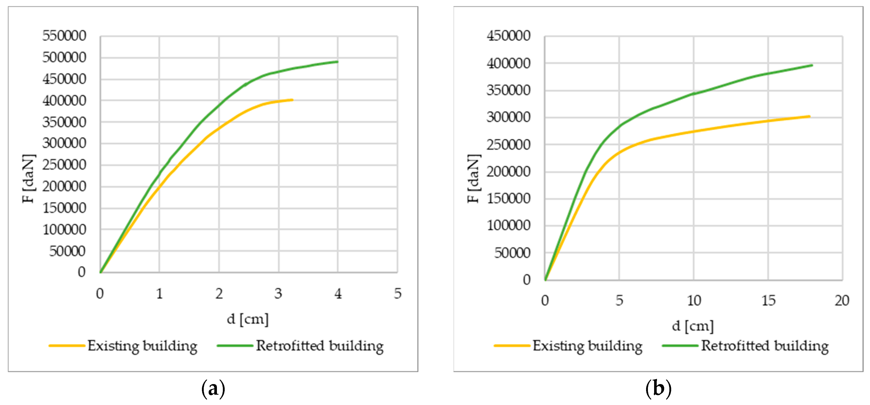
Figure 12.
Seismic risk class of the RC building: before (a) and after (b) the retrofit intervention.
Figure 12.
Seismic risk class of the RC building: before (a) and after (b) the retrofit intervention.
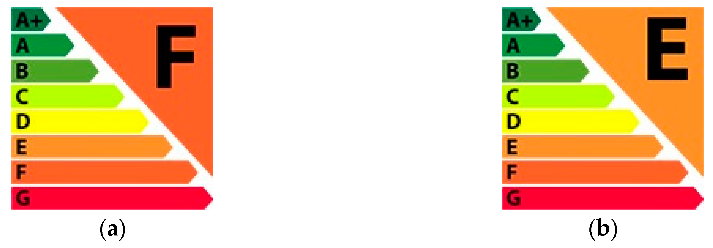

Table 1.
Mechanical properties of concrete.
| Rck1 [MPa] | E1 [MPa] | γ1 [kg/m3] |
| 30 | 31447.2 | 2500 |
1 Characteristic cubic compression strength (Rck), elasticity modulus (E) and dead weight (γ).
Table 2.
Mechanical properties of steel.
| ftk1 [MPa] | fyk1 [MPa] | E1 [MPa] | γ1 [kg/m3] |
| 540 | 450 | 210000 | 7850 |
1 Characteristic ultimate strength (ftk) and yielding strength (ftk) values, elasticity modulus (E) and dead weight (γ).
Table 3.
Mechanical properties of steel profiles.
| ftk1 [MPa] | fyk1 [MPa] | E1 [MPa] | γ1 [kg/m3] |
| 390 | 320 | 210000 | 7850 |
1 Characteristic ultimate strength (ftk) and yielding strength (ftk) values, elasticity modulus (E) and specific weight (γ).
Table 4.
Mechanical properties of anchoring bolts.
| ftk1 [MPa] | fyk1 [MPa] | E1 [MPa] | γ1 [kg/m3] |
| 800 | 640 | 210000 | 7850 |
1 Characteristic ultimate strength (ftk) and yielding strength (ftk) values, elasticity modulus (E) and specific weight (γ).
Table 5.
Vertical loads applied to the floors.
| Level | G11 [kg/m2] | G21 [kg/m2] | Q1 [kg/m2] |
| Intermediate floors | 370 | 120 | 200 |
| Top floor | 500 | - | 120 |
1 Self weight and defined dead loads (G1), undefined dead load (G2) and live loads (Q).
Table 6.
Results of the pushover analysis on the existing building.
| Dir. | ddam1 [cm] | Fdam1 [kN] | dcu1 [cm] | Fmax1 [kN] | d*y1 [cm] | F*y1 [kN] | K*1 [kN/cm] |
| X | 0.61 | 1323.7 | 3.25 | 4096 | 1.5 | 3008 | 2002 |
| Y | 1.75 | 1100.7 | 17.22 | 3058 | 3.49 | 2102 | 602 |
1 Displacement (ddam) and shear (Fdam) corresponding to the first damage, ultimate displacement (dcu), maximum shear (Fmax). Asterisked terms indicate the equivalent bilinear yielding displacement (d*y), shear (F*y) and stiffness (K*).
Table 7.
Design stiffness of the Resisto 5.9 Tube system.
| Level | H1 [m] | d01 [cm] | Fi1 [kN] | Ksi1 [kN/cm] | rk1 | KRi1 [kN/cm] |
| 4 | 12 | 2.13 | 5074 | 2382.2 | 5.18 | 12349.6 |
| 3 | 9 | 1.84 | 4428 | 2406.5 | 12475.9 | |
| 2 | 6 | 1.30 | 2952 | 2270.8 | 11772.1 | |
| 1 | 3 | 0.59 | 1478 | 2505.1 | 12986.8 |
1 Level height from the ground (H), floor displacement (d0) shear (Fi) and stiffness (Ksi) of the existing structure, proportionality factor (rk), design floor stiffness of the exoskeleton (KRi).
Table 8.
Design stiffness of the Resisto 5.9 Tube system.
| Level | nRi | KRi, s [N/mm] | Li [mm] | Ai [mm2] | bi [mm] | ti [mm] |
| 4 | 93 | 6639.6 | 1291.4 | 50 | 50 | 0.99 |
| 3 | 93 | 6707.5 | 1291.4 | 50 | 50 | 1.00 |
| 2 | 93 | 6329.1 | 1291.4 | 47 | 50 | 0.94 |
| 1 | 53 | 12251.7 | 1317.9 | 97 | 50 | 1.93 |
Table 9.
Results of the pushover analysis on the retrofitted building.
| Dir. | ddam1 [cm] | Fdam1 [kN] | dcu1 [cm] | Fmax1 [kN] | d*y1 [cm] | F*y1 [kN] | K*1 [kN/cm] |
| X | 0.67 | 1579.8 | 3.63 | 4852 | 1.64 | 3562 | 2168 |
| Y | 1.82 | 1242.8 | 18.97 | 4100 | 4.52 | 2679 | 593 |
1 Displacement (ddam) and shear (Fdam) corresponding to the first damage, ultimate displacement (dcu), maximum shear (Fmax). Asterisked terms indicate the equivalent bilinear yielding displacement (d*y), shear (F*y) and stiffness (K*).
Table 10.
Comparison of the seismic analysis results: percentage variation of the capacity curve’s parameters due to the application of the Resisto 5.9 Tube system.
Table 10.
Comparison of the seismic analysis results: percentage variation of the capacity curve’s parameters due to the application of the Resisto 5.9 Tube system.
| Dir. | ∆d*y | ∆dcu | ∆Fmax | ∆K* |
| X | +9.3% | +11.7% | +18.5% | +8.3% |
| Y | +29.5% | +10.2% | +27.5% | -1.5% |
Table 11.
Seismic safety index ζE before and after the retrofit intervention.
| ζE Existing Building | ζE Retrofitted Building | ζE Increase |
| 0.26 | 0.42 | +0.16 |
Table 12.
Seismic risk class of the RC building before and after the retrofit intervention: PAM and IS-V parameters.
Table 12.
Seismic risk class of the RC building before and after the retrofit intervention: PAM and IS-V parameters.
| Status | PAM [%] | PAM Class | IS-V [%] | IS-V Class | Assigned Class |
| Before Retrofit | 5.644 | F | 26 | E | F |
| After Retrofit | 4.035 | E | 42 | D | E |
Disclaimer/Publisher’s Note: The statements, opinions and data contained in all publications are solely those of the individual author(s) and contributor(s) and not of MDPI and/or the editor(s). MDPI and/or the editor(s) disclaim responsibility for any injury to people or property resulting from any ideas, methods, instructions or products referred to in the content. |
© 2024 by the authors. Licensee MDPI, Basel, Switzerland. This article is an open access article distributed under the terms and conditions of the Creative Commons Attribution (CC BY) license (http://creativecommons.org/licenses/by/4.0/).
Copyright: This open access article is published under a Creative Commons CC BY 4.0 license, which permit the free download, distribution, and reuse, provided that the author and preprint are cited in any reuse.


