1. Introduction
Polymer matrix composites (PMCs) are being used for structural and ballistic protection applications. This numerical study of the capabilities of PMCs to withstand ballistic impact came about as a follow-up to a research proposal to utilize PMCs as the structural materials in large power transformer (LPT) tanks [
1]. LPTs are a key component of the electrical grid, and their reliability is critical for health, safety, and economic prosperity. However, in the last ten years, certain LPTs have been the target of vandalism. Aside from the rifle attack on the Metcalf substation in California on April 16, 2013 [
2] which caused roughly
$16 million in damage, an analysis done by the Wall Street Journal reported that there were 274 cases of power grid vandalism in the United States between 2012 and 2014 [
3,
4]. The authors of [
1] suggested that PMCs can favorably mitigate impact damage and other challenges as the reliability of grid components becomes critical in the presence of increasing vandalism. The current study aims to model hybrid combinations of two common PMCs with and without a Polyurea (PU) coating to identify potential structures that could minimize cost and weight, two very significant factors in many materials selection decisions. Results of our ballistic simulations of PMCs with and without an extra coating of protective Polyurea (PU) presented in this work could apply to any PMC plates utilized for structural or protective purposes.
PMCs for ballistic impact protection have been widely studied both experimentally and numerically. Authors of [
5], provided a comprehensive review of various PMCs and the factors that influence their reaction to impacts including material, geometry, environment, and projectile type and velocity. The authors of [
6], using a continuum damage mechanics model, modeled the effects of projectile size and velocity for a carbon fiber/epoxy panel. The authors of [
7] both modeled and conducted experimental impact tests on Carbon Fiber Reinforced Polymer (CFRP) panels for both non-woven and woven architectures. In [
8], ballistic impact tests of Glass Fiber Reinforced Polymer (GFRP) composites were conducted. In this study they found that the ballistic performance could be improved by adding expensive nanoparticles to the epoxy matrix. For the purpose of verifying our model, we utilized a less recent study by Kasano [
9] in which he experimentally tested the ballistic limit and residual velocities for CFRP plates as a function of the impact velocity.
Hybrid structures have also been evaluated. In experimental work done by [
10,
11], the authors proposed a PMC laminate sandwich architecture consisting of two different composite types that offered the best impact resistance over several other composite architectures with an improvement of over 40 times. The laminate consisted of face sheets of 5 unidirectional CFRP plies (top and bottom) with a core made up of 10 plies of unidirectional GFRP. The improved impact resistance of the sandwich structure was attributed to the process of delamination at the CFRP/GFRP interfaces which was shown to absorb much of the energy. However, the investigation was limited to quasi-static loads.
PU’s ballistic resistance capability is known to be due to its so-called ‘high-strain rate sensitivity’. Under high strain rates (10
5/s to 10
7/s ) [
12,
13], certain types of PU respond with high shear strength which can be higher than that of steel. The shear strength of PU in a ballistic event greatly depends on the thickness of the substrate [
13]. In a high pressure and strain rate situation, PU’s shear strength can exceed most engineering materials that are used in protection technology. When used as a coating on metals and composites an impact resistant polymer should have a significant glass transition temperature well below LPT operating temperatures which could be -20 to about 300 °C. It has been shown in [
14] and discussed by [
12], that for PU the strain-rate-induced glass transition (the broad α-transition) leads to enhanced energy dissipation upon impact. This occurs when the deformation rate is comparable to the rate of motion of the soft segment in the PU chain, which for several PUs is of the order of 10
5 to 10
7/s at room temperature. At quasi-static strain rates (10
-2/s) this α-transition occurs around -50 to -60
oC, well below LPT operating temperatures. For the LPT tank, PU could offer significant additional advantages in terms of durability and resilience for protection against environmental elements. PU has an estimated 75-year life span [
15], with good resistance to ultraviolet (UV) light.
PU has been used as a coating for several substrates such as steel, aluminum, ceramics, etc. [
13], [
15,
16,
17,
18,
19] but has only been recently studied as a coating for brittle composites such as CFRP to improve blast resistance [
20]. A very interesting observation made in [
20] was that placing the PU on the rear side of the CFRP textile structure provided significantly better spalling protection than having the coating on the front side. Zhang et al [
21], have provided a comprehensive review of PU and its use in blast and impact protection for various substrates. For ballistic protection, the authors indicated that PU is generally placed on the front of the substrates, and this is more feasible in LPT tanks as it avoids PU contact with the transformer fluid. The authors also identified certain disadvantages such as the difficulty in repairing damaged coatings, spraying and coating problems due to uneven mixing, and the elevated costs of its preparation and application, which can greatly influence its effectiveness when used as coating for protection. In a related study on the impact behavior of porcelain bushings on LPTs, it was shown that the bushings can be protected against impact when coated with Polyurethane-Urea (LINEX) [
22,
23,
24]. With the advent of big data and machine learning, convolutional neural networks (CNN) have been used to predict the dynamic cohesive properties (DCPs) of a bicontinuosly nanostructured copolymer such as PU [
25]
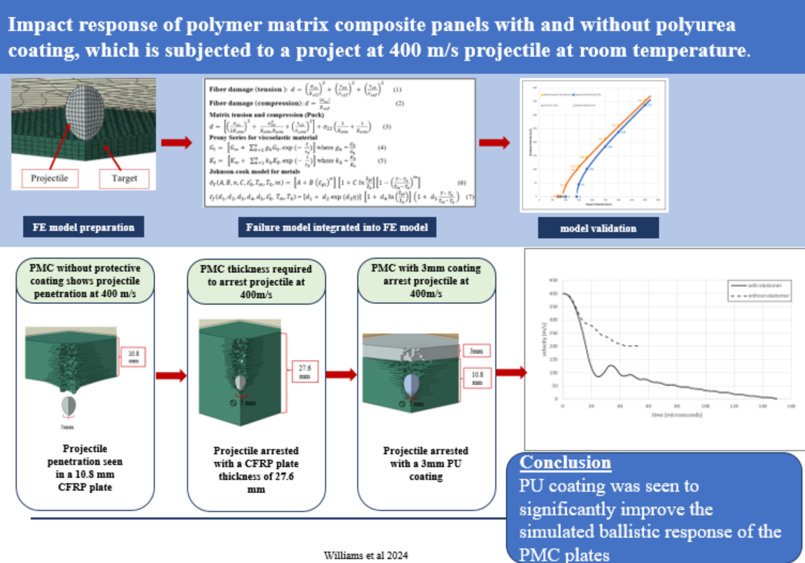
In this work, Finite Element (FE) Analysis was used to analyze the ballistic impact resistance of PMC materials (see
Figure 1). To accomplish this, versatile FE models were built using Python scripts for use with the Abaqus Explicit solver, utilizing various material models. For the verification of the FE model, the work done by [
9] and [
26] was utilized where a carbon fiber cross-ply PMC plate served as the target.
Once the validations were completed, simulations were conducted using CFRP and GFRP to determine minimum thicknesses required to prevent ballistic penetration of a 400 m/s 12.7 mm spherical steel projectile. In addition, the effect of composite hybridization was evaluated using laminates with half CFRP and half GFRP. Finally, the significant benefit of adding a thin PU coating to the underlying substrates was analyzed numerically. While as noted there have been experiments conducted to evaluate the ballistic protection benefits of adding a PU coating to PMCs, we believe this is the first flexible numerical simulation to be conducted.
2. Materials and Failure Models
Failure models describing the onset and evolution of failure used in our numerical simulations were a “User Subroutine” in ABAQUS [
27] developed by Dassault Systems for the PMCs, the Prony series and a Virtual User Defined Field (VUSDFLD) for PU [
28,
29], and the Johnson-Cook model (JC) [
28] for the projectile. The script developed allows for the joint application of diverse material models when analyzing several different impact conditions.
A cross-ply CFRP epoxy laminate and a cross-ply GFRP epoxy laminate were analyzed individually, and in combination as a hybrid composite. The properties of the CFRP laminae came from [
26]. The properties of GFRP were computed using Helius Composite software and its references and knowledge network [
30]. The properties for these materials are displayed in
Table 1.
The user subroutine for composite progressive damage, was made available by Simulia [
26] in their documentation. The material properties of CFRP linked to the user subroutine that was applied in this study were also from [
26] and are summarized in
Table 1. The user subroutine was enhanced by utilizing Hashin’s damage model for composites [
31] for the initiation and evolution of the through-thickness damage to the fiber and matrix for PMCs. In the subroutine, the Hashin damage criterion was specified for the fiber failure mode while the Puck criterion [
26,
32] was applied to the matrix damage modes. The relationship between fiber and matrix damage utilized in the user subroutine is given by [
26]:
Matrix tension and compression (Puck)
where
are the effective stress tensors,
are the fiber tensile, compressive, and shear strengths.
are the matrix tensile failure stress in the 1 and 2 directions (1 is the fiber direction),
is the matrix compressive failure stress in the 2-direction, and
, is the matrix failure shear stress.
For PU, a single composition was chosen to demonstrate the effectiveness of PU coatings in attenuating impact on the PMC panels. The particular PU composition ratio, namely 4-parts by weight of Versalink P-1000 diamine to 1-part of Isonate 143L isocyanate, was selected for two reasons. Firstly, this composition has been extensively studied by research groups funded by the US Office of Naval Research at UCLA and UCSD, with the 4:1 ratio being generally considered optimal for impact applications [
33]. Secondly, a Prony series for the viscoelastic response of this PU composition was available [
29]. This composition ratio is close to being stoichiometric since the equivalent weights are 575-625 g/equivalent for the Versalink P-1000 [
34], and 144.5 g/equivalent for the Isonate 143L [
35] resulting in a mass ratio of 3.98-4.35:1 for a stoichiometric ratio of 1:1 for the amine to isocyanate groups.
The material properties of the particular PU investigated by [
29] are listed in
Table 2. PU exhibits a linear and viscous response in its stress/strain characteristics. The time-dependent behavior of PU is attributed to the material’s hard and soft segments, i.e., the motion of the chain at different time scales. PU has been modeled as a linear viscoelastic isotropic solid material by [
29] using the material’s shear relaxation modulus G. The Prony series was used in [
21] and in this work to model the relaxation of a polymer consisting of
n decaying exponentials. Equations (4) and (5) describe the time dependent shear and bulk moduli of PU under high strain rates [
36].
The terms g
k and k
k in equations (4) and (5) are the ratios of the shear and bulk moduli to the shear and bulk moduli of the kth element at the onset of deformation, and
τk is the relaxation time of the kth element, that is the time it takes to ‘relax’ the stress to about 38% (1/
e) of the initial applied stress.
, and
are the shear and bulk moduli at time t = 0,
are the shear and bulk moduli of the first element in the generalized Maxwell model. These are the viscous properties needed for input in a Prony series in the time domain in the Abaqus explicit simulation. In this work, 14 terms of the Prony series, provided by the experimental work of [
29] were used in the simulation.
Finally, a Virtual User Defined Field (VUSDFLD) [
28] subroutine was used to assess the response of PU. VUSDFLD is a custom constitutive model used for modeling the high strain rate behavior of PU. The VUSDFLD subroutine computes the strain in the material at each time step using the Prony series and then compares it with a critical strain value at which the material fails. With limited published data on critical strain values for PU at the strain rates under study, we selected a failure value of 0.25 to perform element elimination from the model. We believe this value of 0.25 is conservative given stress-strain curves for various PUs that we reviewed [
13,
37,
38].
For the projectile, the material model and the calibrated Johnson-Cook (J-C) failure parameters as shown in
Table 3 were used. The material response is linear elastic up to its yield strength, after which it deforms plastically until its failure strain [
28]. The yield stress (
) and the strain at failure (
[
39] are expressed by Equations (6) and (7).
In equations 6 and 7, η= -p⁄q represents the triaxiality, defined as the hydrostatic pressure divided by the deviatoric stress or (Von Mises stress), is the reference strain rate, T is the attained temperature of the material, Tm is the melting point, T0 is the ambient temperature or the reference temperature, is the plastic strain, and the plastic strain rate, C is the viscous effect constant, n is the strain hardening exponent, m is the thermal softening exponent, and are damage parameters.
During impact, the high plastic strain rate causes the dissipation of energy as heat which raises the temperature (T) of each of the impacted elements in the model. The temperature rise is exclusive to each element and there is no heat conduction assumed between the elements. The inelastic heat fraction applied in the simulation was 0.9, that is, 90% of the energy dissipated by the plastic deformation was converted to heat.
3. Independent Verification of FE Models
To confirm the validity of the PMC model, a comparison was made to an experiment conducted by [
9]. In that work, a 5 mm diameter spherical steel projectile of mass 0.51 g was fired at three different velocities at a multi-ply composite panel and the residual velocities were measured. The composite panel was a [0,90,0]
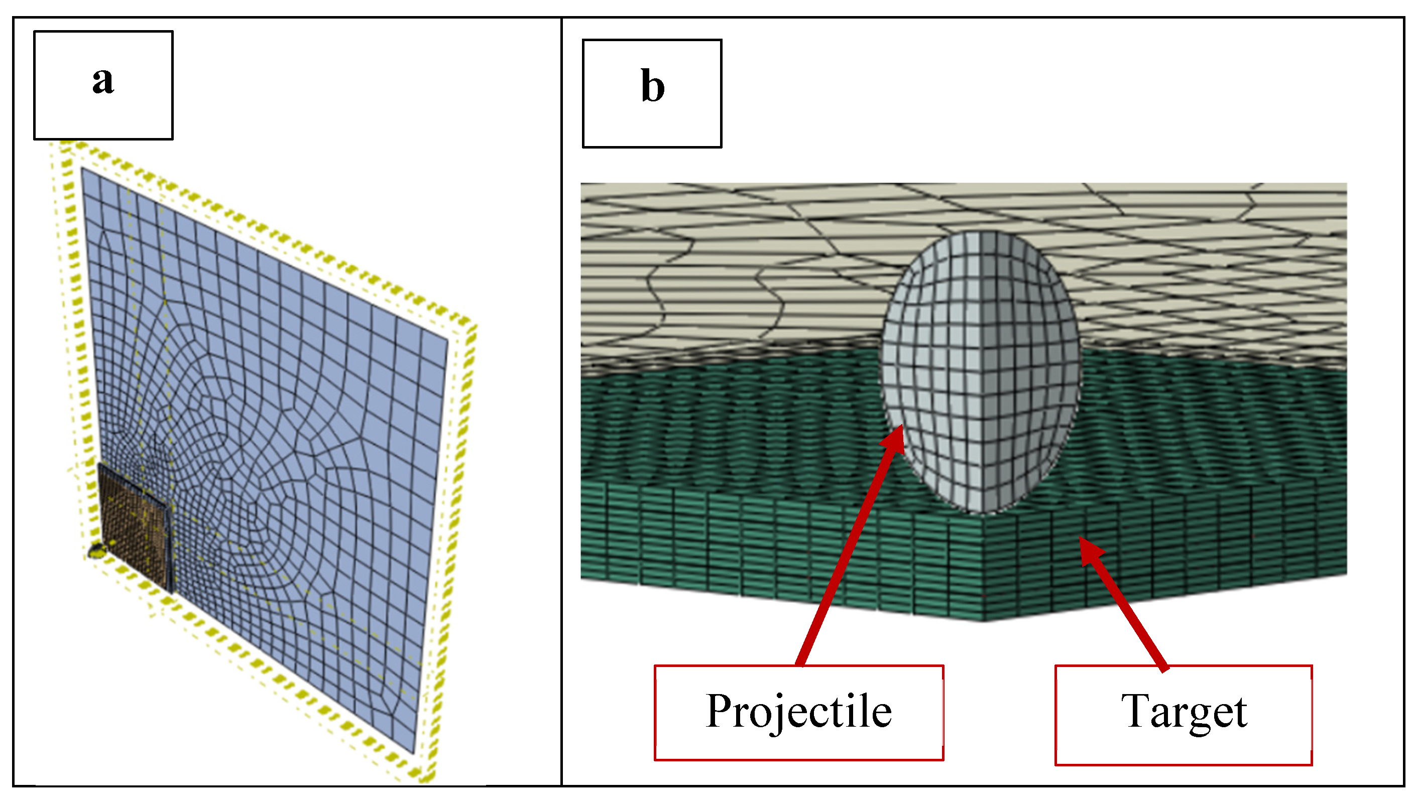
ns laminate with 12 or 18 layers of CFRP, in which n=2 or 3 respectively, and the panel thickness ranged from 1.8 mm to 2.7 mm. For this validation, the 12-layer (n=2) experiment was used. A PMC 200 x 200 mm panel was simulated with a target area of 50 x 50 mm to reduce computation costs. Taking advantage of symmetry, a quarter model was developed as seen in
Figure 1a and b. The architecture, plies, and thickness of the model followed those of the experiment [
9]. The target was divided into sub-laminates, where each [0,90,0] sub-laminate was separated by a cohesive zone. The cohesive zones were modeled with cohesive elements (COH3D8) with maximum degradation set to 1 kJ.
The finite element model is shown in
Figure 1. The region of the plate outside the target area was modeled with shell elements (S4R) to reduce the computational cost. The target region was represented with first-order C3D8R continuum elements [
26] (layer-by-layer) to capture the damage in detail. Edges of the plate were fixed in place. To make the model more versatile, a python script was used to develop the model where geometry conditions, mesh parameters, contact parameters, speed of the projectile, and boundary conditions were defined as variables.
The exact properties of the steel projectile used in the experiment in [
9] were not stated. In our work cold- rolled steel was used to model the projectile as a deformable spherical solid following [
26]. We specifically selected cold-rolled 4340 steel for the projectile. The projectile yield followed the Johnson-Cook parameters listed in
Table 3. These complete parameters may be used to simulate both the initiation and propagation of the damage in the projectile under elastoplastic conditions. However, this study limits the projectile to a perfectly elastic material in order to simplify the model.
A mesh sensitivity study was conducted for the target with mesh sizes of between 0.3 and 1.0 mm, and for the projectile, with mesh sizes of between 0.35mm and 0.55mm. A good correlation was found with the experimental result at mesh sizes of 0.85 mm in the planar directions and at one element per ply in the thickness direction (0.15 mm) for the target and 0.4 mm for the projectile. We utilized the tools developed by [
24] but compared our simulation results directly with the experiment [
23] due to some concerns about the geometry assumptions used by [
24].
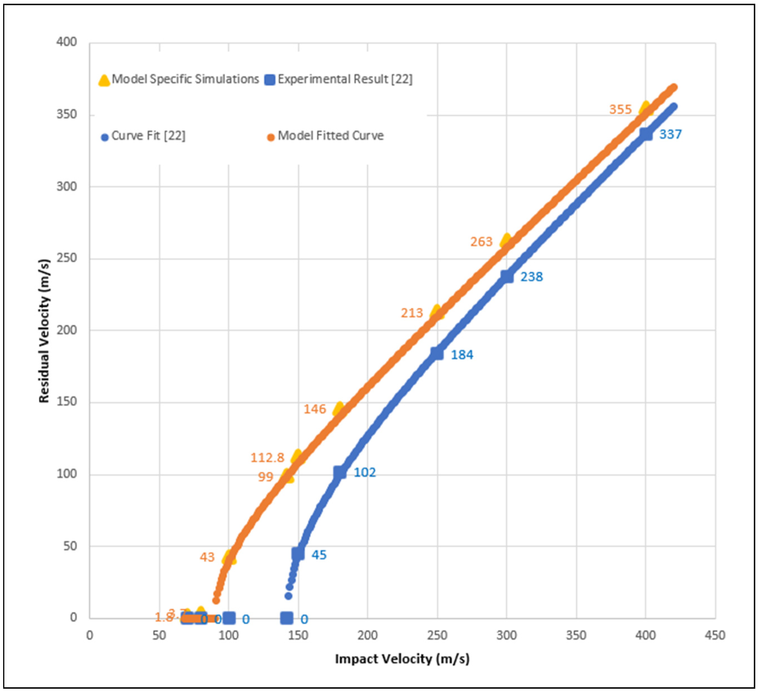
The bottom curve in
Figure 2 is the fitted curve from [
9] for the 12-layer panel. This fitted curve utilizes the function:
where
is the impact velocity,
is the ballistic limit, and α is a function of the mass of the projectile and the masses of the fragments released from the plate upon impact (for more information see [
9]). Certain points along that curve are specified for comparison with the model where those same velocities were simulated. A curve using the same parameters as the experiment (i.e., with α = 0.9) is fitted to those points and displayed in the top curve of
Figure 2. It is to be noted that while the variation in the residual velocities decreases as impact velocity increases as shown in
Figure 2, the difference in the residual kinetic energies of the projectile between the experiment and the simulation stays roughly constant. Using either measure, the simulation produces a conservative estimate of the energy dissipated by the composite plates and thus the actual results should be better than those predicted by the modeling.
4. Impact Response of CFRP and GFRP Plates
Next, the impact resistance of CFRP and GFRP composites was evaluated using the same model that was verified in the previous section. All of the simulations utilized individual unidirectional 0.2 mm plies in a [0/90/0] architecture. Thus each [0/90/0] sub-laminate was 0.6 mm thick. The target and plate lateral dimension were the same as those used in the PMC verification. Again, C3D8R elements were used in the target area and S4R elements in the non-target area. Lateral dimensions of 0.85 mm and thickness dimensions of 0.2 mm were used for the PMC target element mesh sizes. The thickness dimension of the PMC mesh corresponded to one element per ply. The edges of the plates were likewise fixed.
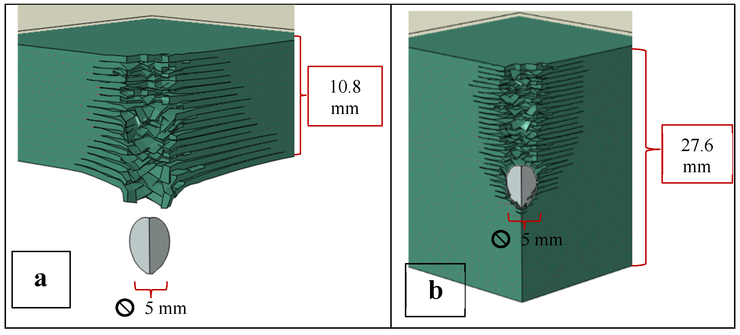
At first 18 layers of sub-laminates for a total thickness of 10.8 mm for both CFRP and GFRP were found in the simulation to be penetrated by a 400 m/s 4340 steel spherical projectile with a 5 mm diameter. The PMC thickness is similar to the standard thickness of an LPT tank [
1]. The thicknesses for both the CFRP and the GFRP plates were then increased by adding additional sub-laminates to find the minimum thickness that would prevent penetration. Subsequently, a consistent thickness of 27.6 mm was evaluated to allow for the comparison of penetration depths and to see whether penetration depths would significantly change if the thicknesses were increased beyond the minimum penetration prevention thickness. See
Figure 3 a and b for simulation schematics. The results are presented in
Table 4(a).
Following the proposal of [
10], two hybrid architectures of CFRP/GFRP and GFRP/CFRP (where the projectile impacts the first material listed before the second and both components were of equal thickness) were evaluated. In both cases, the initial 10.8 mm thick hybrid plates were unable to prevent full penetration from the 400 m/s steel projectile. The same process to estimate minimum thicknesses and penetration depths as discussed in the prior paragraph was then conducted for these hybrid structures. The results are presented in
Table 4(b).
The results in
Table 4 show that the projectiles were arrested with a 19.8 mm thick CFRP plate and a 21.2 mm GFRP plate. When the thicknesses for both of these structures were increased to 27.6 mm, the arrest distances were similar to those for the near minimum arrest thickness plates. The results in
Table 4a clearly show that there are critical arrest distances for the projectile at 400 m/s which are between 17.1 and 17.3 for CFRP and between 21.2 and 20.8 for GFRP. It can also be seen that when the thickness was increased by approximately 30-40%, the critical arrest distances did not change materially. This suggests that we can simulate the projectile arrest with plate thickness relatively close to the arrest distance. However, this might create a bulge at the backface of the plate containing delaminations which could affect the projectile arrest process. The projectile would be stopped but the backface would be severely damaged leading to a partial arrest. Consistent results were obtained using hybrid CFRP + GFRP plates, regardless of their order (Table 6b). However, the significant improvements from hybridization as reported by [
10] and [
11] were not observed in our simulations.
5. The Effect of PU Coating
The modeling of the PMCs with PU utilized the same PMC mesh sizes and a mesh size of 0.3 mm for the PU. With the addition of 3 mm of PU to the original 10.8 mm thick plates, the CFRP/PU plate successfully arrested the 400 m/s projectile as shown in
Table 5.
Figure 4 illustrates the simulated results. However, with the GFRP plate, the addition of the PU only allowed for the partial arrest of the projectile. A hybrid combination of PU/CFRP/GFRP with a total thickness of 13.8 mm also successfully arrested the projectile. Table 7 in comparison with
Table 5 reveals the significant effect of the 3 mm PU coating on CFRP and GFRP plates having 10.8 mm thicknesses.
For the CFRP and the hybrid CFRP-GFRP plates with the PU coating, the 400 m/s projectile was fully arrested. However, the coated GFRP allowed partial penetration. In this case, the thickness of the coating or of the GFRP would have to be increased in order to achieve a full arrest, but likely nowhere near the approximately 20 mm thickness required without the coating. Thus, by applying a 3 mm coating of PU, the thickness of the CFRP composite plate to just prevent penetration could be significantly reduced.
These results show that PU could play a major role in the impact protection of advanced PMCs, for example in the protection of LPT tanks. To further demonstrate this effect,
Figure 5 and
Figure 6 are presented. We analyzed the damage formation process in the PU/CFRP/GFRP laminate (
Figure 5), from the onset of the projectile impact until the projectile is fully arrested inside the laminate. Eight stages of the damage progression between 0 to150 microseconds are shown.
Figure 6 shows the velocities of the projectile in the hybrid laminate with and without the PU coating.
Several important observations can be made when analyzing the data presented in figs. 5 and 6. First, the projectile decelerations (change in velocities) are markedly different between the coated and uncoated composites in
Figure 6. The reduction in the velocity of the projectile in the coating is significantly larger than in the composite. For example, the time it takes for the projectile to decelerate from 400 to 200 m/s with PU is approximately 15 microseconds while for the same deceleration without PU it takes about 45 microseconds which is 3 times longer. Thus the PU has a significantly beneficial effect on the deceleration of the projectile. At somewhere between 10 and 20 microseconds the projectile has just penetrated the PU coating (
Figure 5). Note that while the coated plates fully arrested the projectile and brought its velocity to zero, the projectile retained an exit velocity of about 200 m/s after penetrating the uncoated hybrid laminate.
Using estimated costs of
$25,
$5, and
$22.50 /kg and densities of 1750, 1870, and 1071 kg/m
3 for CFRP, GFRP, and PU respectively, along with the simulated results from
Table 4 and
Table 5,
Table 6 summarizes the modeled thicknesses to pervent penetration for all six material combinations studied. It also estimates the costs and masses of the material options. It is clear from this table that adding a 3 mm coating of PU reduces the thickness, cost, and mass required to prevent penetration for any of the substrate materials.
7. Conclusions
This research analyzed CFRP, GFRP, and CFRP/GFRP plates either uncoated or coated with Polyurea under projectile impact at 400m/s. This was done by performing dynamic FE simulations using a steel projectile. Using our independently verified FE models, we determined that the perforation of the plates and the arrest of the projectile all strongly depend on the type of materials simulated and their thicknesses.
Simulated CFRP, GFRP, and CFRP/GFRP composite plates behave in a very similar fashion under 4340 steel projectile impact. The damage evolution in the composites was essentially the same with the arrest depths ranging from 17 to 21 mm. When the thicknesses of the plates were increased by about 30-40 %, the depths of arrest did not significantly change.
PU was seen to significantly improve the simulated ballistic response of the PMC plates. When a 3 mm PU coating was applied to a 10.8 mm CFRP plate, the steel projectile was arrested at about 12 mm depth. Meanwhile, there was a partial penetration for GFRP of the same thickness and coating. The CFRP/GFRP hybrid with coating showed a similar arrest depth as that of the CFRP with coating. We showed that the projectile decelerated from 400 to 200 m/s in 15 microseconds for the PU/CFRP/GFRP sample while it took three times longer to reach that same reduced velocity in the 10.8 mm uncoated hybrid sample.
While the value of PU coatings on PMCs has previously been shown experimentally and numerically for other purposes as mentioned in the introduction, in our research, we have evaluated the required thickness of PU to be applied to the standard LPT tank thickness to prevent ballistic penetration for a specified projectile. Based on our numerical predictions, PU could be more efficient at improving ballistic resistance than simply increasing the base material thickness.
Based on our validation, our models underestimate the energies absorbed by the composites. We believe this indicates that actual composite plates could perform even better than what the simulations have shown. Therefore, for projectile impacts up to at least 400 m/s, a CFRP/GFRP composite could potentially be a good material for LPT tanks when PU coatings are applied.
Depending on the design and material requirements for the substrate, a different selection of materials could be made. For example, if the structural needs could be met by GFRP,
Table 6 would indicate that GFRP with a PU coating is the cheapest option to provide ballistic protection. On the other hand, if cost is not a consideration, PU + CFRP is the lightest option. PU + CFRP + GFRP may be a good compromise between cost and mass. For each of the three underlying substrates, adding PU instead of increasing thickness reduced both cost and weight. These results come from testing 10.8 mm thick substrates with 400 m/s impacts so further analysis would be required for other base thicknesses and velocities. Of course, before being used in any real-life applications, our simulation results would need to be verified experimentally. The cost of potential experimental verification is presently beyond available financial resources of the authors. However, the number of costly experiments could be significantly reduced by application of these simulation results. Therefore, the models and the simulation results presented in this work could be quite valuable in the design of the actual experimental impact testing on the selected composite panels for application in LPT tanks.