Submitted:
26 July 2024
Posted:
29 July 2024
You are already at the latest version
Abstract
To further enhance the intelligence level of coal mining faces and achieve autonomous derivation, learning, and optimization of shearer navigation cutting, this paper proposes the methods of shearer digital twin navigation cutting motion planning based on the concept of shearer autonomous navigation cutting technology and intelligent coal mining face digital twins. The study includes the digital twin theory and the construction method of the shearer digital twin navigation cutting motion planning system based on this theory. Based on the digital twin theory, a shearer digital twin navigation cutting motion planning system was constructed. This system supports the service functions of shearer cutting digital twin, dynamic navigation map digital twin, reinforcement learning environment construction, and motion planning through the physical perception layer, comprehensive data layer, and digital-model fusion analysis layer. Finally, by comparing the effects of the DQN-NAF and DDPG deep reinforcement learning algorithms in the shearer motion planning task within the constructed digital twin environment, the results show that the DQN-NAF algorithm demonstrates better performance and stability in solving the shearer digital twin motion planning task.
Keywords:
Shearer
; Motion Planning
; Digital Twin
; Reinforcement Learning
1. Introduction
Coal is currently the main energy source in China. The intelligent construction of coal mines is of great significance for promoting the transformation and upgrading of the coal industry and achieving high-quality development [1,2]. As of the end of April this year, 1,922 intelligent coal mining faces and 2,154 intelligent tunneling faces have been built nationwide. The National Energy Administration issued the "Notice on Further Accelerating the Intelligent Construction of Coal Mines to Promote High-Quality Development of Coal," which requires large coal mines to accelerate the full intelligentization of mining systems. At the same time, the "Guidelines for the Construction of the Coal Mine Intelligent Standard System" proposes the establishment of digital twin system standards, covering reference architecture, information models, equipment models, data interfaces, and digital twin service applications for entire mines. The working scenario of the coal mining Workface is shown in Figure 1.
The development of digital twins can be divided into three stages. The first stage is the concept proposal. In 2002, Professor Michael Grieves [3] from the University of Michigan first proposed the concept of the digital twin in a Product Lifecycle Management (PLM) course. At that time, industrial software such as PLM and simulation had gradually matured, laying the foundation for building digital twins in virtual space.
The second stage is the application period in aerospace. From 2011 to 2012, a series of outlooks on the application of digital twins in aircraft were released by NASA and AFRL (Air Force Research Laboratory). Digital twins began to be applied early in the aerospace industry. In 2013, Dr. Mark T. Maybury, the Chief Scientist of the U.S. Air Force, conducted a research survey on global future technology trends and summarized the report "Global Horizons," viewing Digital Thread and Digital Twin as game-changing opportunities [4]. NASA hoped that by 2025, each aircraft delivered to the U.S. military would be accompanied by an as-built digital model, allowing for the estimation of lifespan and reliability in virtual scenarios. NASA defined the digital twin of an aircraft as an as-built model or system that integrates multi-physics, multi-scale, and probabilistic simulations. The as-built model itself should be tightly coupled with external shapes, internal structures, and computational fluid dynamics models, and be able to map the physical aircraft through sensor data and flight history data [5].
The third stage is the multi-industry expansion application period. Currently, the application of digital twins has evolved from the aerospace field to multiple industries. Industrial enterprises represented by GE and Siemens are accelerating the construction of digital twin solutions to provide innovative enabling services for industrial enterprises. The rapid development of digital twins is closely related to the rise of new-generation information technology and the widespread application of the industrial internet in multiple industries [6]. In the future, the application of digital twins in the industrial field will continue to deepen, accelerating the digital transformation of industrial enterprises. Digital twins are an important component of the Industry 4.0 digital process.
In 2014, Shirong Ge, while leading a National Key Basic Research Development Program "973" project, first proposed an innovative concept: the autonomous navigation cutting technology for shearers based on a coal seam Geographic Information System (GIS).
This technology marked a new concept in the development of shearer cutting technology [7]. It utilizes detailed coal seam detection maps for planning cutting movements and adopts navigation control technology to achieve unmanned shearer cutting operations. This effectively addresses the challenges brought by coal seam variations, allowing real-time adjustment of cutting paths and ensuring the autonomy of operations. By 2020, Shi-Rong Ge further proposed the concept of the Digital Twin Smart Mining Workface (DTSMW) [8]. This is a highly realistic three-dimensional mirror scenario of the mining workface with strong data visualization, human-machine interaction, and full-process self-optimization. The system achieves bidirectional communication and information exchange between the digital twin and the physical entity, comprehensively perceiving the physical space of the unmanned fully mechanized mining workface, monitoring the production process and performance in real-time, and providing three-dimensional visual reproduction of virtual scenarios. This significantly enhances the intelligence level of the fully mechanized mining workface.
Based on the concepts of shearer autonomous navigation cutting technology and the Digital Twin Smart Mining Workface, this paper proposes the theory and methods for digital twin navigation cutting motion planning of shearers. Digital Twin (DT) technology is used to create virtual models of physical entities, achieving bidirectional mapping, dynamic interaction, and real-time connection between the physical world and the digital world. The core content includes digital twin theory, the digital twin of the shearer's cutting state, the digital twin of the dynamic navigation map, and the key parts of motion planning through deep reinforcement learning based on digital twins. The specific content is shown in Figure 2.
First, the digital twin theory includes three main aspects: the physical scene of the smart mining face, the construction theory of the digital twin model, and the mechanisms of digital twin-driven interaction and system evolution. The research on the physical scene of the intelligent mining face is subdivided into the constituent elements of the intelligent mining face and the constraint relationships of the equipment environment [9], providing a solid foundation for the construction of the digital twin model. The composition of the digital twin model includes physical entities, twin models, and twin data models. The digital twin-driven interaction and evolution theory is further refined into the digital twin-driven operation mechanism and the logic of virtual-real interaction.
Next, supported by the digital twin theory, a digital twin navigation cutting motion planning system for the shearer is constructed, as shown in Figure 3. Firstly, the cutting state of the shearer is digitally twinned by combining the digital twin model with real-time sensor data. Secondly, a finely detailed coal seam navigation map that can be dynamically updated is created to provide real-time, accurate navigation path information. Finally, a reinforcement learning environment based on the digital twin is established to achieve interaction between the physical and virtual models, and reinforcement learning optimization algorithms are used for the digital twin navigation cutting motion planning of the shearer.
3. Reinforcement Learning Algorithms
Reinforcement learning is a type of machine learning method [14,15]. The training process of reinforcement learning is to find the state-action mapping function that maximizes the expected total reward of the agent [16,17]. Reinforcement learning differs significantly from the widely applied supervised learning. Another important feature of reinforcement learning is the need to balance and trade off the proportions of "exploration" and "exploitation" during the training process [18,19,20].
Deep reinforcement learning algorithms used for motion planning have become a research focus in the field of navigation control. Deep reinforcement learning algorithms suitable for shearer navigation and cutting motion planning must be capable of handling multi-dimensional state spaces and continuous outputs. Within the framework of reinforcement learning algorithms, the entity that interacts with the environment and makes decisions is called an agent. The object with which the agent interacts is defined as the environment. As shown in Figure 14, the interaction process between the agent and the environment is displayed, which is key to achieving autonomous learning and decision-making.
From the perspective of algorithmic principles, reinforcement learning can be categorized into methods based on value functions and policy gradients, as well as hybrid strategies that combine these two approaches. These different methods reflect the diversity in the design and implementation of strategies in reinforcement learning, as shown in Figure 15. Algorithms based on value functions mainly focus on evaluating and optimizing the value of each state, thereby indirectly deriving the optimal strategy. In contrast, methods based on policy gradients directly seek to optimize strategies within the policy space, improving expected returns by adjusting policy parameters. The combined approach attempts to utilize the advantages of both strategies to achieve more robust and effective learning outcomes.
3.1. Improved DQN Normalized Advantage Function Algorithm (DQN-NAF)
The Deep Q-Network Normalized Advantage Function (DQN-NAF) algorithm, as shown in Figure 16, involves the design of two neural networks: the implementation network and the target network. The network output includes three main components: the triangular matrix I(s), the action vector φ(s), and the estimated state value function V(s). During training, DQN-NAF uses the TD(N) method to update network weights. The implementation network estimates the Q value for each state-action pair by calculating Q(s, a) = V(s) + A(s, a), where A(s, a) is the action advantage function, indicating the degree to which choosing action a is better than the average action. The target network is used to estimate the maximum Q value of the next state V(s'). The loss function is the mean squared error between the predicted Q values and the target Q values. Additionally, the DQN-NAF algorithm includes an experience replay pool, which stores sampling data obtained from interactions with the environment, supporting batch learning and non-online updates, which helps stabilize and improve the efficiency of the learning process.
The DQN-NAF algorithm utilizes two sets of structurally identical feedforward neural networks, as shown in Figure 17, namely the reality neural network and the target neural network. These networks include an input layer, two hidden layers (each containing 128 neurons), and an output layer. The input to the network is the state S of the agent, and the output includes three key components: the state value function V(s), the action vector φ(s), and the column vector L(s) used to construct the diagonal matrix. In this paper, the tanh function is used at the output layer to limit the range of outputs, while the ReLU function is used in the preceding hidden layers.
The implementation details and operational procedure of the DQN-NAF algorithm can be referred to in the pseudocode provided in Table 1.
3.2. Deep Deterministic Policy Gradient Algorithm (DDPG)
The Deep Deterministic Policy Gradient (DDPG) algorithm further develops on the Actor-Critic architecture by introducing a dual-network structure. This includes the reality network and the target network, which belong to the Actor and Critic modules, respectively. In this setup, the Actor network's responsibility is to receive input states and produce specific actions, while the Critic network's task is to evaluate the potential Q-values of these actions. The two parts of the network cooperate through continuous training and updates to optimize their performance. Figure 18 details the schematic of the Deep Deterministic Policy Gradient (DDPG) algorithm.
As shown in Figure 19, the Actor part is responsible for generating a deterministic action vector from the input state. In this part of the network, all layers except the output layer use the ReLU activation function, while the output layer employs the tanh activation function to ensure that the range of action outputs is limited to [-1, 1]. The number of neurons in the hidden layers is set to 128. For the Critic part, the agent's state and actions are fed into two separate first hidden layers, each containing 64 neurons. The outputs of these two layers are then merged and fed into a second hidden layer, which has 128 neurons. The network configuration of the Critic part in terms of activation function selection is the same as that of the Actor, using ReLU activation function before the output layer and tanh activation function for the output layer itself.
The implementation details and operational procedures of the DDPG algorithm can be referred to in the pseudocode provided in Table 2.
4. Construction of a Digital Twin Reinforcement Learning Environment
The essence of reinforcement learning lies in the agent's need to learn through continuous interaction with the environment and a constant process of trial and error, which forms the core training process of reinforcement learning. ML-Agents is an open-source framework developed using Unity3D, specifically designed for training agents in virtual environments to accomplish a variety of tasks. The ML-Agents framework provides a powerful and flexible environment, supporting developers in implementing and testing complex reinforcement learning algorithms in the virtual world, thus further promoting the integration and application of machine learning and virtual simulation technologies. Python, with the help of the Pytorch software tool, can quickly set up and complete the neural network computation part, hence it is widely used in data analysis and artificial intelligence fields. Using Python to implement deep reinforcement learning algorithms and communicate with ML-Agents software for joint simulation is illustrated in Figure 20.
In Unity3D, building a three-dimensional coal seam and intelligent mining equipment model for joint analysis digitalizes all elements of the production process, creating a more comprehensive and accurate dynamic map that integrates equipment models into reinforcement learning, which will provide more effective guidance for actual production. Based on the virtual reality engine Unity3D, the digital twin of the shearer, scraper conveyor, and hydraulic support on the three-dimensional coal seam model is implemented to construct a reinforcement learning environment, with the overall research framework shown in Figure 21.
4.1. Coal Seam Environment Construction
First, import the three-dimensional geological body model and intelligent mining equipment model files into the Assets directory of the Unity3D project. In the Project window of Unity3D, locate the imported models and instantiate them by dragging into the Scene Editor's Hierarchy window, at which point the models will appear in the scene. Select the model object in the scene, click 'Add Component' in the Inspector window and choose Rigidbody. This component is a core part of the Unity3D physics engine, responsible for handling physical properties such as acceleration, mass, and damping. Activate the 'Use Gravity' property of the Rigidbody component and adjust parameters such as Mass and Drag to achieve the desired physical effects. As shown in Figure 22, the digital twin shearer, scraper conveyor, and hydraulic support move downward under the influence of gravity, and after colliding with the virtual coal seam floor, they adaptively fit onto the complex virtual coal seam bottom.
After constructing a dynamic and precise three-dimensional coal seam model, it becomes very important to study how the coal seam model can specifically guide the operation of the shearer. Among other things, the three-dimensional coal seam model not only provides a baseplate for equipment layout but also serves another important function: providing data on the coal seam roof and floor that can guide production for the shearer at the current cutting drum. Using a planar function triangulated mesh model would generate a large amount of discrete data points that are difficult to handle. As shown in Figure 23, converting the surface model into a volumetric model allows for the sorting of generated data before storing it in a database. When the shearer reaches the current position, scripts are used to extract data and achieve the extraction of the contour position of the coal seam roof at the intelligent mining face.
After converting to a volumetric model, the drum can be set as Spheres bounding spheres, requiring only the storage of the center coordinates and radius. The roof and floor are set with AABB bounding boxes, also requiring only the storage of center coordinates and the radii along the three axes. In intersection tests, calculate the distance between the centers of the spheres; if it is less than the sum of the radii of the two bounding boxes, they are deemed to intersect, which also makes the solution speed of the spherical bounding box the fastest. After Unity3D reads the body coordinates, it uses the LineRenderer component to connect and draw the curve of the coal seam roof at the working face, as shown in Figure 24.
4.2. Digital Twin Scene for Shearer
The Unity3D engine requires the establishment of parent-child relationships for objects composed of multiple structural levels or those with defined motion relationships between them, to enable more accurate and efficient operation and control of each level. Declarations of the Transform component for each part include the shearer body, left and right drums, left and right rocker arms, left and right height-adjusting cylinders, left and right slide shoes, etc. By analyzing the main structures and functions of the drum-type shearer, parent-child relationships are established in Unity3D, with definitions for setting the parent of each child object using Transform.SetParent(Transform parent) , as shown in Figure 25.
As shown in Figure 26(a), after adding movement scripts to the left and right slide shoes, the shearer can move along the scraper conveyor track. To enable the left and right guide slide shoes and the left and right support slide shoes to move in coordination and further enhance the accuracy of the shearer's movement in the digital twin environment, additional colliders are added to the shearer. First, a BoxCollider (box-shaped collider) is added to the hydraulic supports and the scraper conveyor track.
By adding a BoxCollider to the left and right guide slide shoes, interference issues between the shearer and the scraper conveyor can occur during the movement of the shearer along the conveyor. As shown in Figure 26(b) and 26(c), optimizing and adding a CapsuleCollider (capsule-shaped collider) to the left and right support slide shoes ensures that the collider conforms to the external shape of the support slide shoes. This effectively prevents mechanical blockages that could stop movement due to the support slide shoes colliding with the BoxCollider in the middle trough at undulating positions on the baseplate, allowing the defined collider of the shearer to slide through when colliding in the middle trough.
The rotation of the shearer's drum utilizes the rotation feature of the Rigidbody component in Unity3D, applying a rotation speed to the drum to enable it to rotate and cut the coal wall. The arm height adjustment achieves the rotational movement of the shearer's arm setting joints Joint1, Joint2, and Joint3, and incorporating the calculation of the shearer arm's angle adjustment (equation 3) into the motion, as illustrated in Figure 27. Through top plate tracking and undercover measurements, the arm adjustment angles θ1 and θ2 are calculated, and the calculated angles are assigned to the arm as the speed of the arm's rotation, achieving the rotational movement of the arm.
4.3. Digital Twin Scene for Hydraulic Supports
Due to the large number of joints in the digital twin hydraulic supports, as shown in Figure 28(a), the use of Hinge Joint components combined with the MGS Machinery plugin in Unity3D can bring greater flexibility to the hydraulic supports. Using the MGS-Machinery plugin in Unity3D, which facilitates mechanical motion and interaction, a hydraulic.cs script is configured on each hydraulic support to drive the digital twin model. The HydraulicSlideFunction and HydraulicLiftFunction control the shifting and lifting processes of the hydraulic supports, respectively. Under the control of the Rigidbody and Collider physics engine and scripts, based on the motion laws of floating linkage mechanisms, the shifting and lifting processes of the hydraulic supports can be achieved. Figure 28(b) shows the state of the hydraulic supports after being lifted.
4.4. Digital Twin Scene for Scraper Conveyor
During the mining process at the intelligent mining face, the scraper conveyor forms an S-shaped bend under the advancement of the hydraulic supports. According to the relevant regulations in the coal industry, when the scraper conveyor is in an S-shape, its horizontal bending angle should range between 1° and 3°, and its vertical deflection angle should range between 3° and 5°. The S-shaped bend of the scraper conveyor is shown as in Figure 29.
In the actual coal mining work environment, the undulation of the coal seam floor is a random and uncertain dynamic environment. In the virtual environment, the digital twin scraper conveyor adapts its posture based on the undulations of the virtual coal seam and the movement constraints between the intelligent mining equipment. As shown in Figure 30, Rigidbody and BoxCollider components are set up in the middle trough of the scraper conveyor, establishing a virtual contact model between the scraper conveyor and the coal seam floor.
5. Digital Twin Reinforcement Learning Training
We will explore and compare the control effects of the DQN-NAF and DDPG algorithms in a digital twin environment applied to the motion planning tasks of coal mining machines. Specifically, we will analyze the performance of these two algorithms in controlling the shearer to determine which method is more suitable for such tasks.
In the task of deep reinforcement learning motion planning for shearer navigation and cutting in the digital twin environment, the reinforcement learning agent controls the digital twin shearer to be towed along the scraper conveyor to reach the target area. The towing and cutting task of the shearer is shown in Figure 31.
In the actual coal mine working environment, the coal seam floor has undulations, and the posture of the shearer itself also changes accordingly. It is necessary to adjust the left and right cutting part cylinders to ensure the edges of the front and rear drums reach within a certain range of the target positions at the top and bottom of the coal seam. The environment for the shearer drum top and bottom tracking task is shown in Figure 32
Training was conducted using a processor 13th Gen Intel(R) Core(TM) i7-13700KF 3.40GHz discrete graphics card NVIDIA GeForce RTX 3090 environment created through Anaconda3 Python environment and ML-Agents software package visualization tool Tensor board 2.11.2 . four scenarios were constructed in ML-Agnets as shown in Figure 33 to accelerate model training.
In this task, both deep reinforcement learning algorithms achieved relatively good results after training the coal mining machine. After exceeding 120,000 training episodes, both algorithms reached convergence for the motion planning task, as shown in Figure 34.
The cumulative rewards, average loss updates of the value function, and average magnitude of the policy loss function are shown in Figure 35.
As shown in Figure 35, the DQN-NAF algorithm converges faster compared to the DDPG algorithm, as seen in the line graph comparing average episode rewards to the number of episodes. The DDPG algorithm exhibits certain instabilities, requiring multiple iterations to finally converge to satisfactory results. From the comparative results of these two typical algorithms, it can be seen that in the task of coal mining machine planning, the DQN-NAF algorithm demonstrates better performance, while the DDPG algorithm is more unstable and shows larger fluctuations during the training process.
6. Conclusions
This paper presents a theory and method for digital twin navigation and cutting planning for coal mining machines, aimed at enhancing the level of intelligence at the coal mining face and achieving autonomous deduction, learning, and optimization of the shearer. The system has achieved an enhancement from perceptual intelligence to cognitive intelligence. The constructed digital twin navigation and cutting motion planning system provides service support for shearer cutting digital twin, dynamic navigation map digital twin, reinforcement learning environment construction, and motion planning through a physical perception layer, comprehensive data layer, and data-model integration analysis layer. Experimental results show that within the constructed digital twin environment, the deep reinforcement learning DQN-NAF algorithm performs better in terms of effectiveness and stability in shearer motion planning tasks than the DDPG algorithm, effectively enhancing the motion planning capability of the shearer.
Author Contributions
Conceptualization and methodology, B.M.; software and validation, Y.L; formal analysis and investigation, Y.G.; resources and data curation, B.M.; writing—original draft preparation and writing—review and editing, B.M.; visualization and supervision, S.G. All authors have read and agreed to the published version of the manuscript.
Funding
This research was funded by the Natural Science Foundation of China (Major Program), grant number 52121003.
Institutional Review Board Statement
Not applicable.
Informed Consent Statement
Not applicable.
Data Availability Statement
The data presented in this study are available on request from the corresponding author.
Conflicts of Interest
The authors declare no conflict of interest.
References
- Wang, G. , Ren, H., Zhao, G., Zhang, D., Wen, Z., Meng, L., Gong, S., 2022. Research and practice of intelligent coal mine technology systems in China. Int J Coal Sci Technol 9, 24.
- Huang Z, Ge S, He Y, Wang D, Zhang S. Research on the Intelligent System Architecture and Control Strategy of Mining Robot Crowds. Energies. 2024;17(8):1834.
- GRIEVES, M. Digital twin: manufacturing excellence through virtual factory replication[R]. Melbourne: U.S. Florida Institute of Technology, 2014.
- EDWARD, M. KRAFT. The Air Force Digital Thread/Digital Twin - Life Cycle Integration and Use of Computational and Experimental Knowledge[C/OL]//54th AIAA Aerospace Sciences Meeting. San Diego, California, USA: American Institute of Aeronautics and Astronautics, 2016[2022-02-25].
- DENNIS J., L. SIEDLAK, OLIVIA J. PINON, PAUL R. SCHLAIS, et al. A digital thread approach to support manufacturing-influenced conceptual aircraft design[J/OL]. Research in Engineering Design, 2018, 29(2): 285-308.
- EUAN BONHAM, KERR MCMASTER, EMMA THOMSON, et al. Designing and Integrating a Digital Thread System for Customized Additive Manufacturing in Multi-Partner Kayak Production[J/OL]. Systems, 2020, 8(4): 43.
- GE Shirong, HAO Xuedi, TIAN Kai, et al. Principle and key technology of autonomous navigation cutting for deep coal seam[J]. Journal of China Coal Society,2021,46(3):774-788.
- GE Shirong, ZHANG Fan, WANG Shibo, et al. Research on the technical architecture of digital twin intelligent coal mining face[J]. Journal of China Coal Society,2020,45(6):1925-1936.
- Miao, B. , Ge, Sh., Guo Y., et al. Construction of digital twin system for intelligent mining in coal mines. Journal of Mining Science and Technology, 2022, 7(2), 143-153.
- Guan Z, Wang S, Wang J, Ge S. Longwall Face Automation: Coal Seam Floor Cutting Path Planning Based on Multiple Hierarchical Clustering. Applied Sciences. 2023;13(18):10242.
- Shibo Wang, Shijia Wang. Longwall mining automation horizon control: Coal seam gradient identification using piecewise linear fitting. International Journal of Mining Science and Technology. 2022;32(4):821-829. [CrossRef]
- Mirjam Holm, Stephan Beitler, Thorsten Arndt, Armin Mozar, Martin Junker, Christian Bohn. Concept of Shield-Data-Based Horizon Control for Longwall Coal Mining Automation. IFAC Proceedings Volumes. 2013;46(16):98-103.
- Dai W, Wang S, Wang S. Longwall Mining Automation—The Shearer Positioning Methods between the Longwall Automation Steering Committee and China University of Mining and Technology. Applied Sciences. 2023;13(22):12168. [CrossRef]
- DENG Y, BAO F, KONG Y, et al. Deep direct reinforcement learning for financial signal representation and trading[J]. IEEE transactions on neural networks and learning systems, 2016,28(3): 653-664.
- TOKIC, M. Adaptive ε-greedy exploration in reinforcement learning based on value differences: Annual Conference on Artificial Intelligence[C]. Springer, 2010.
- SANGIOVANNI B, RENDINIELLO A, INCREMONA G P, et al. Deep reinforcement learning for collision avoidance of robotic manipulators: 2018 European Control Conference (ECC)[C]. IEEE, 2018.
- GAO H, ZHI-QUN H U, LU-HAN Y U, et al. Intelligent Traffic Signal Control Algorithm Based on Sumtree DDPG[J]. Journal of Beijing University of Posts and Telecommunications, 2020,8:55-58.
- LUO S, KASAEI H, SCHOMAKER L. Accelerating reinforcement learning for reaching using continuous curriculum learning: 2020 International Joint Conference on Neural Networks (IJCNN)[C]. IEEE, 2020.
- FLORENSA C, HELD D, WULFMEIER M, et al. Reverse curriculum generation for reinforcement learning: Conference on robot learning[C]. PMLR, 2017.
- KERZEL M, MOHAMMADI H B, ZAMANI M A, et al. Accelerating deep continuous reinforcement learning through task simplification: 2018 International Joint Conference on Neural Networks (IJCNN)[C]. IEEE, 2018.
Figure 1.
The coal mining Workface scenario.
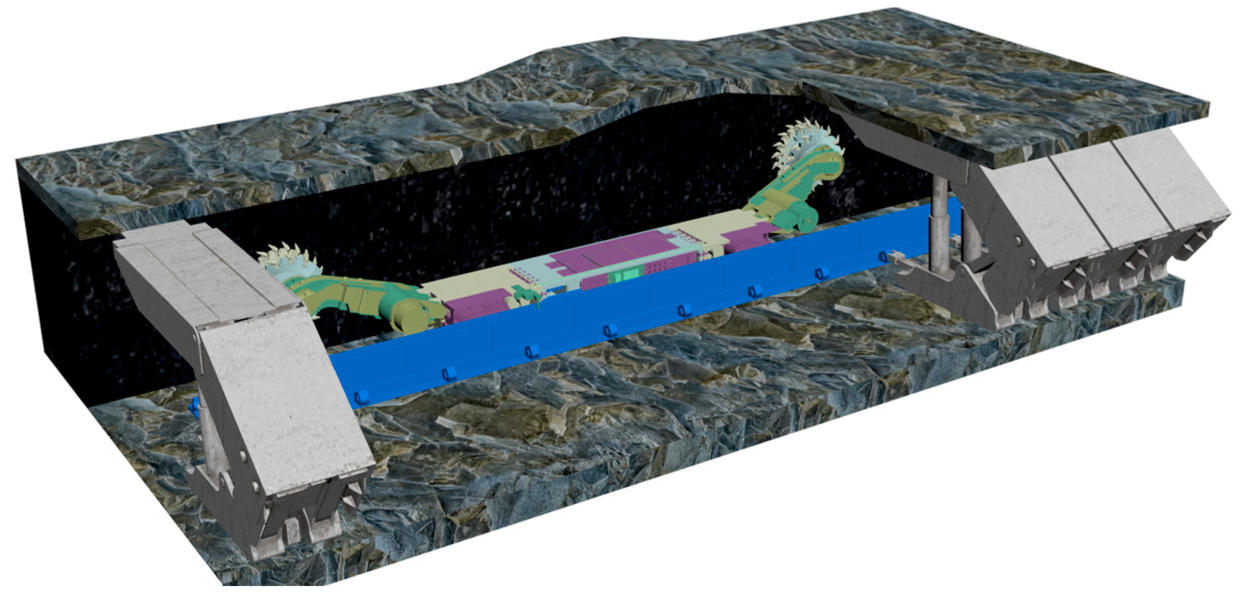
Figure 2.
Technical architecture of the digital twin navigation and cutting path planning for shearer.
Figure 2.
Technical architecture of the digital twin navigation and cutting path planning for shearer.
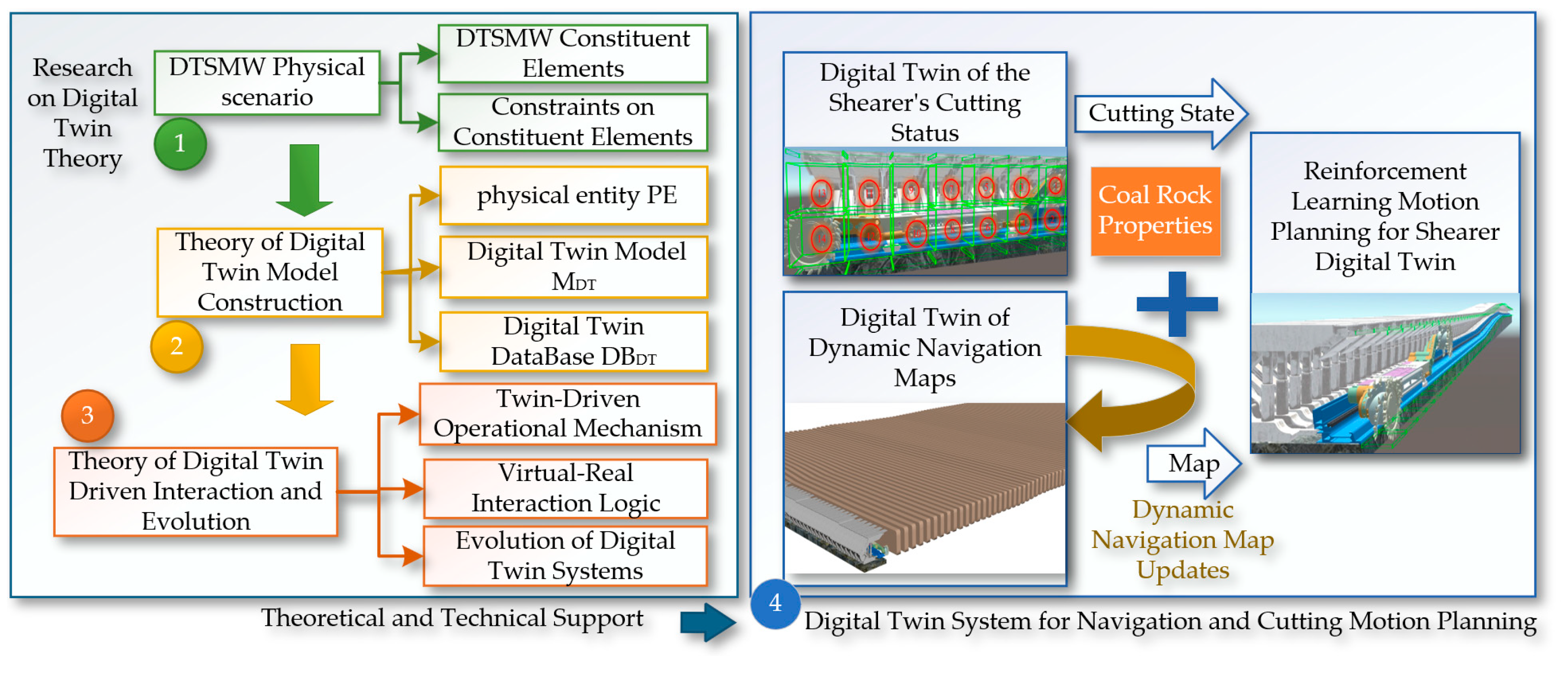
Figure 3.
Digital Twin navigation cutting motion planning system architecture for the shearer.
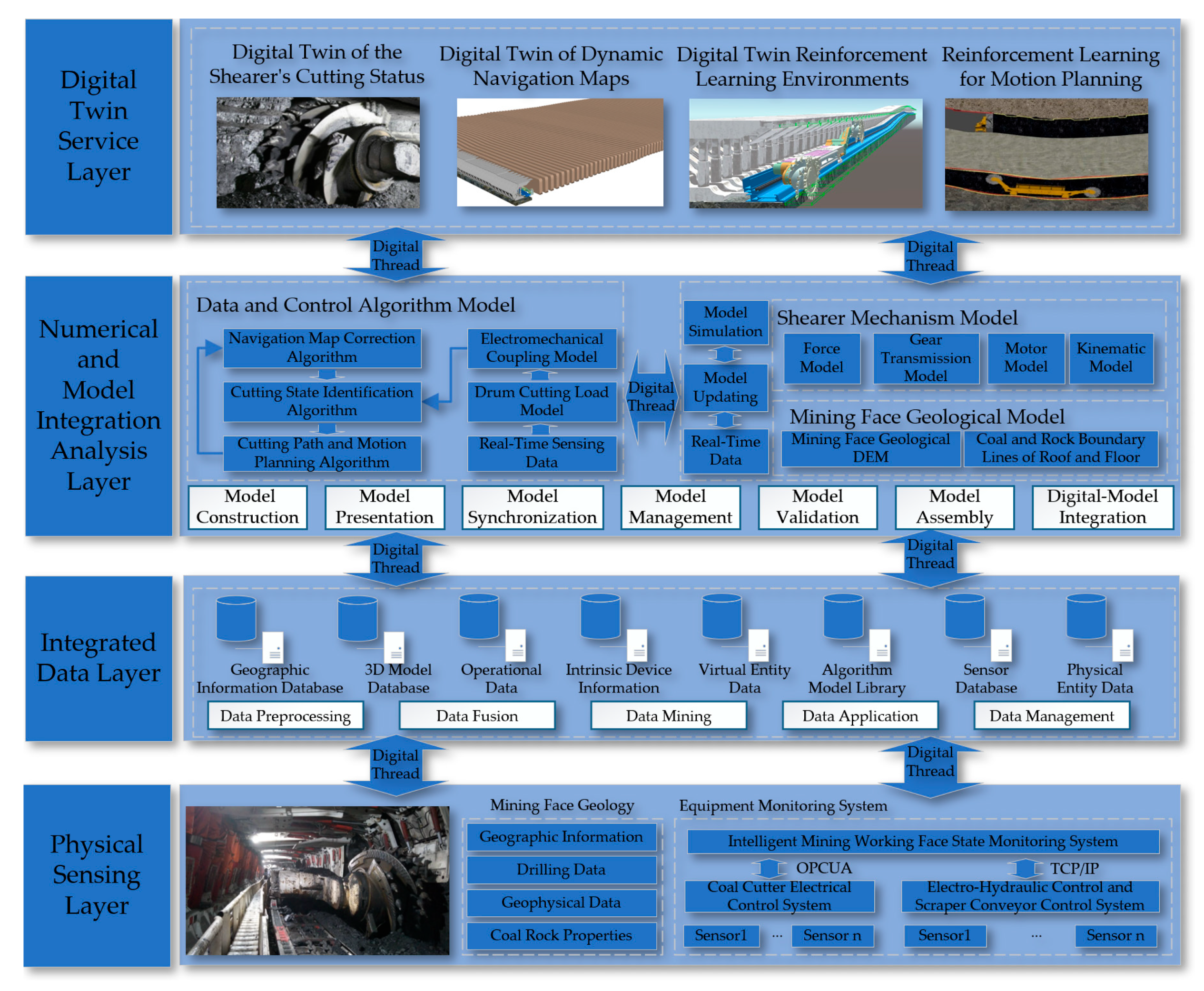
Figure 4.
The construction principle of the digital twin dynamic navigation map.
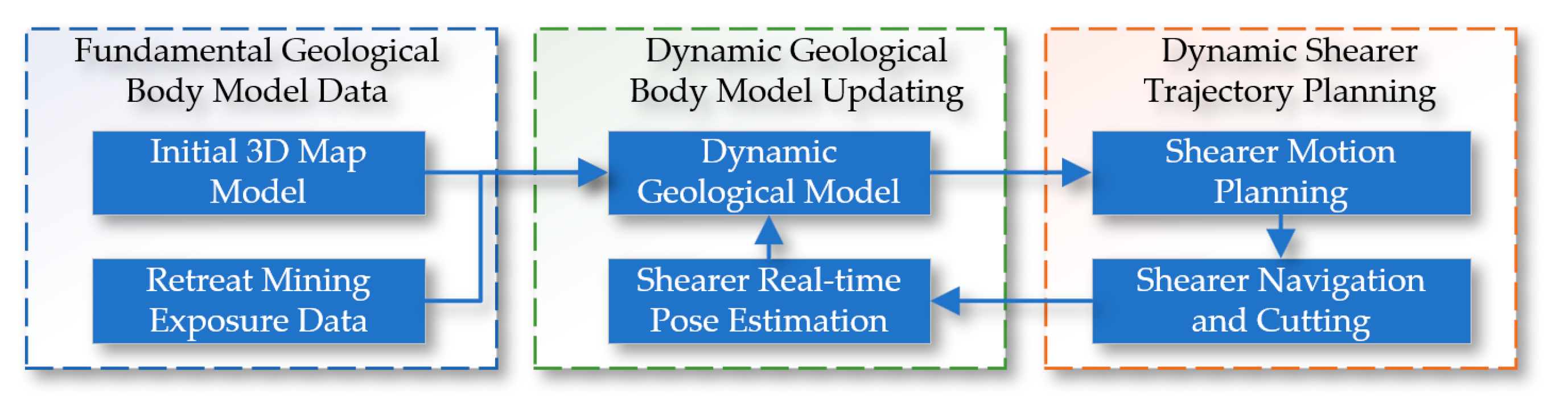
Figure 5.
The construction of the initial three-dimensional coal seam.
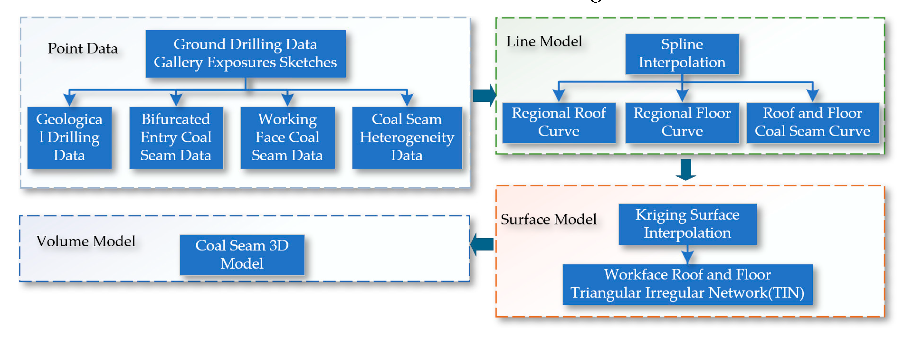
Figure 6.
The initial three-dimensional volumetric model of the coal seam.
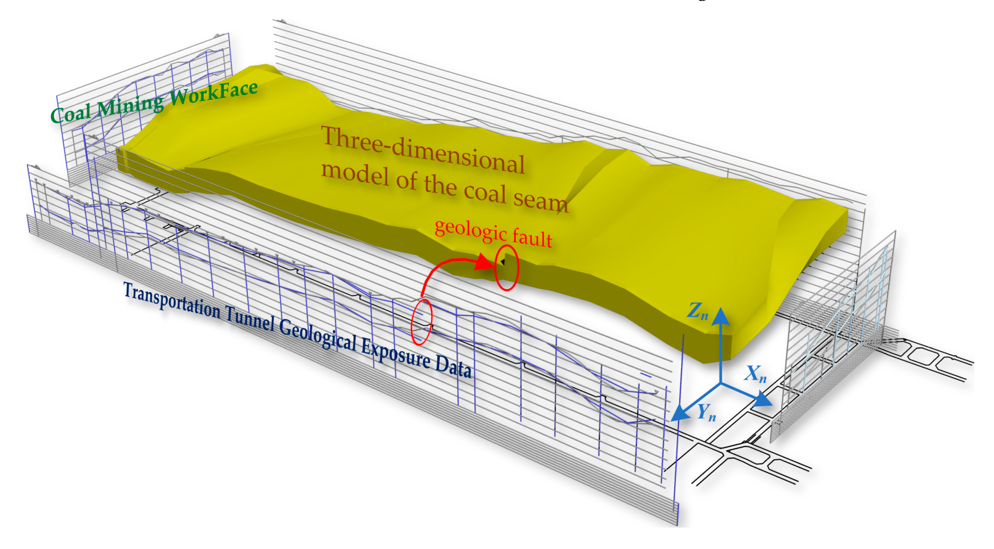
Figure 7.
The architecture of constructing a dynamic 3D geological model.
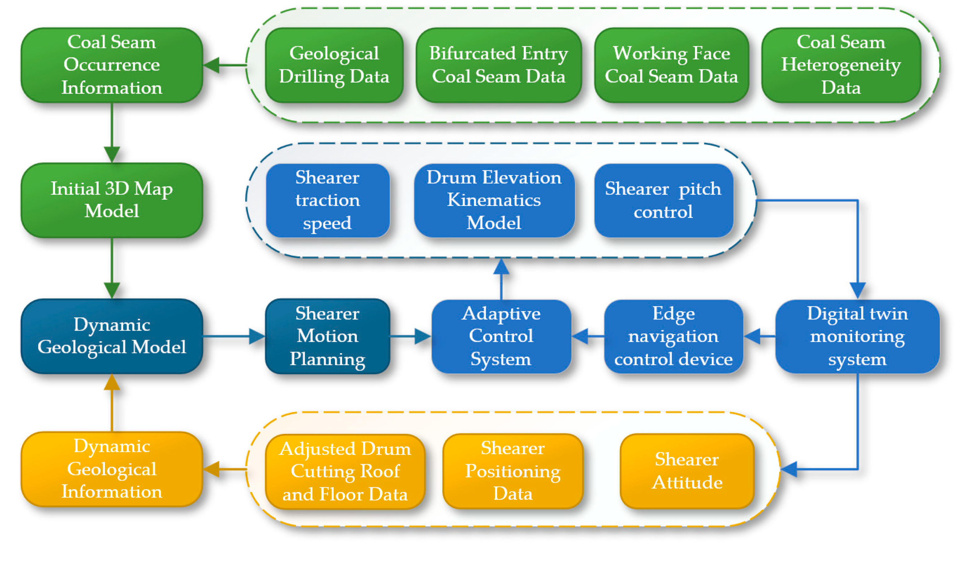
Figure 8.
The related coordinate systems of the shearer.

Figure 9.
(a) The yaw angle; (b) The roll angle; (c) The pitch angle.
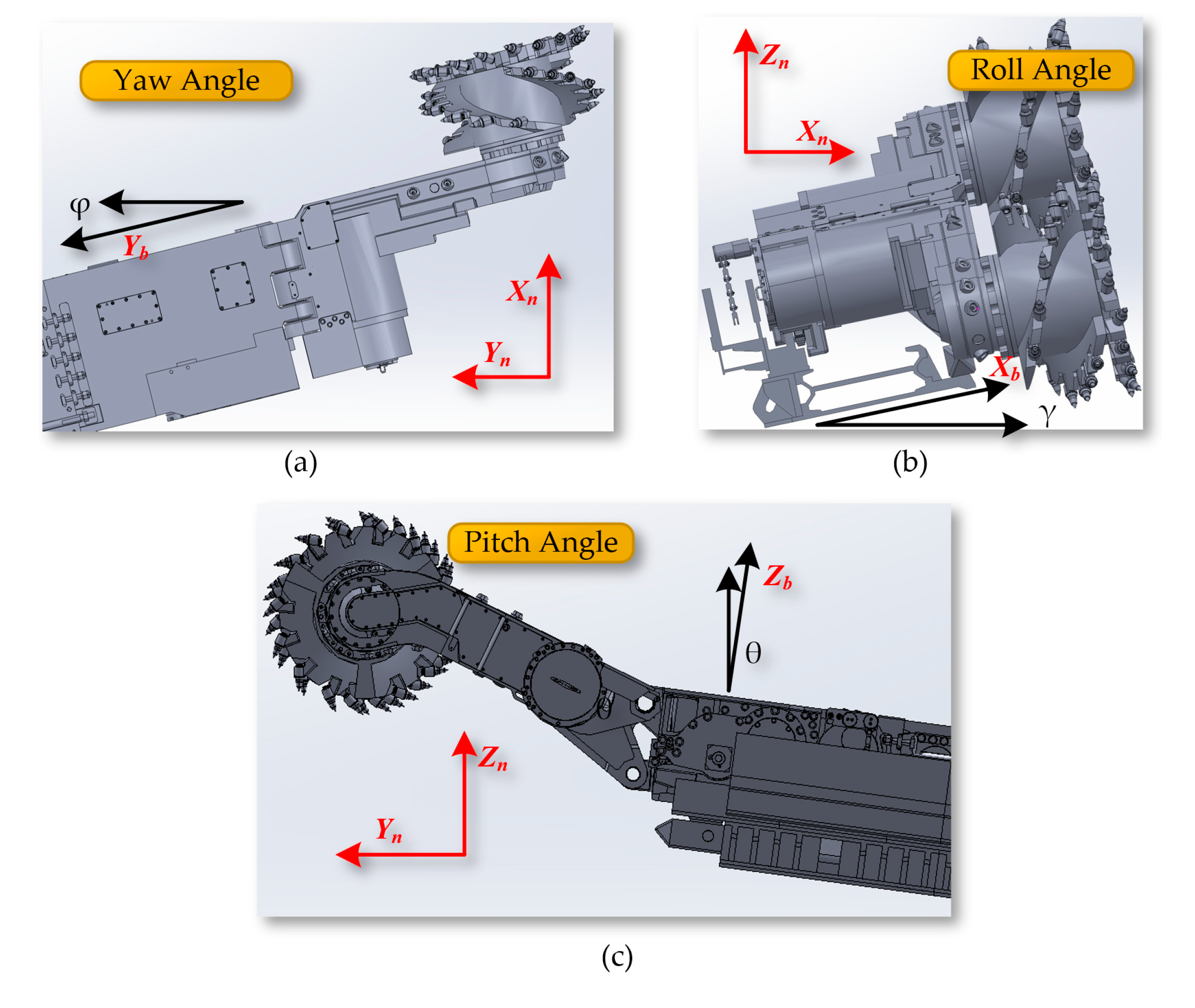
Figure 10.
The shearer's height adjustment mechanism.
Figure 11.
The geological slicing on: (a) The direction Yn; (b) The direction Xn.
Figure 12.
The constraints on the cutting path of the shearer.
Figure 13.
The architecture of the path planning module.
Figure 14.
The interaction process between the agent and the environment.
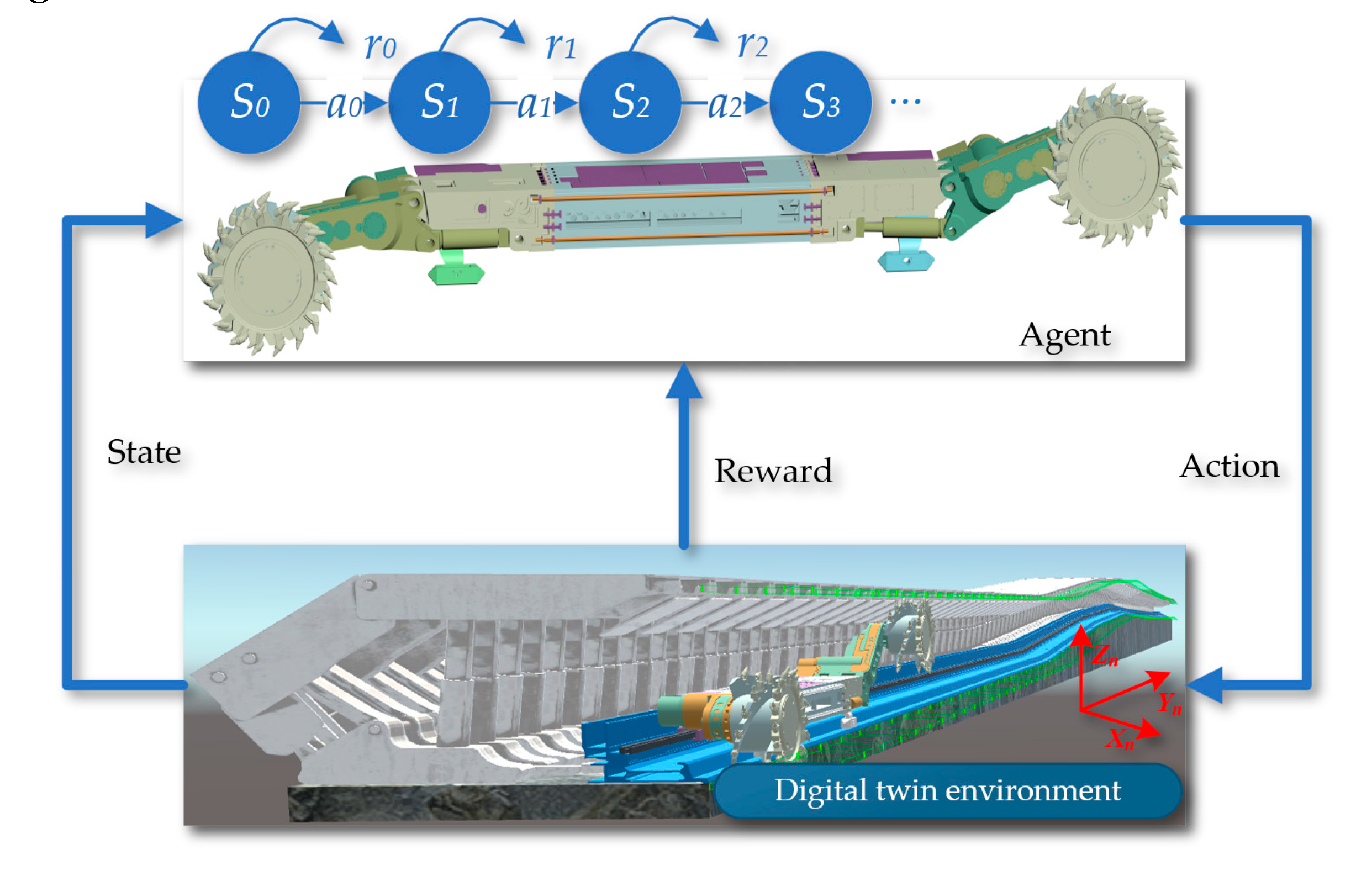
Figure 15.
The architecture of the value functions and policy gradients.
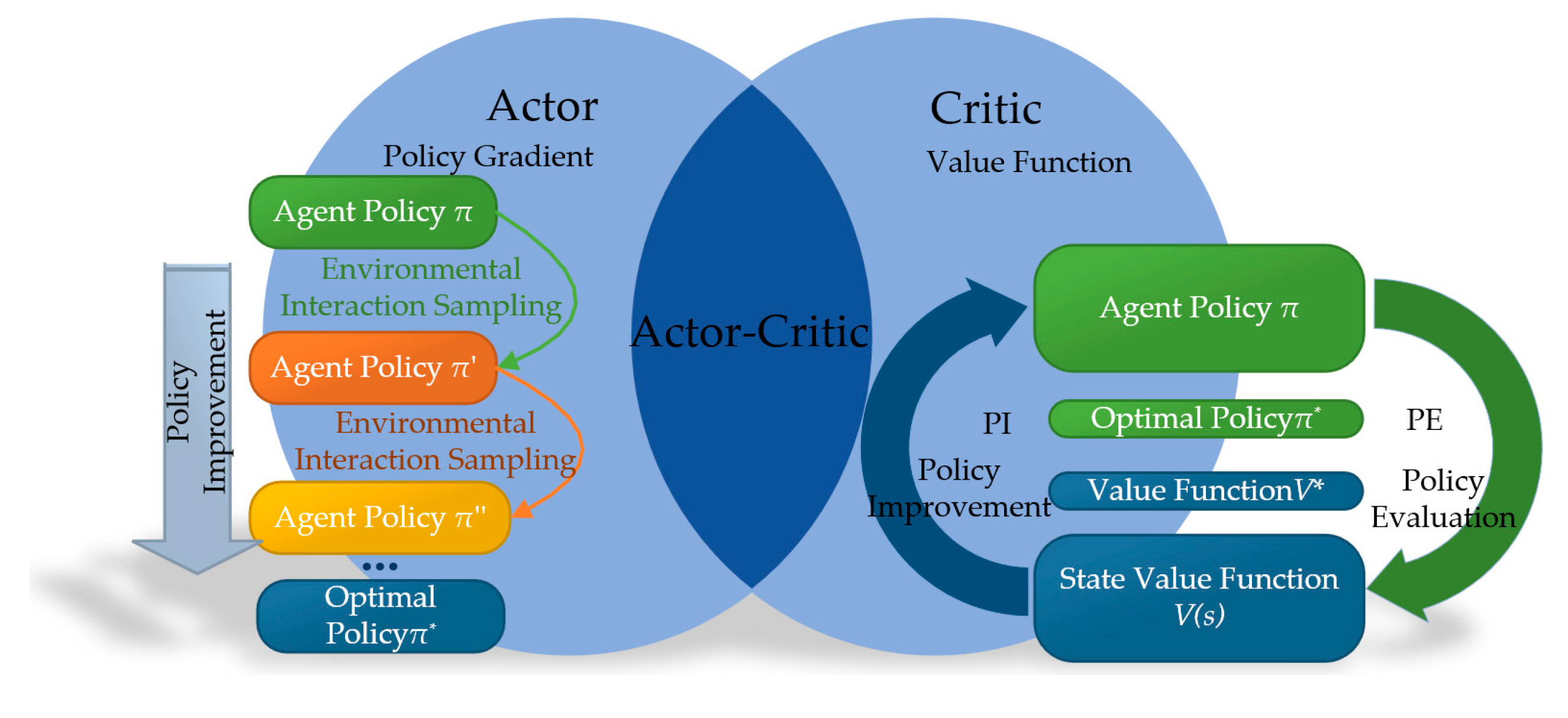
Figure 16.
The schematic of the DQN-NAF algorithm.
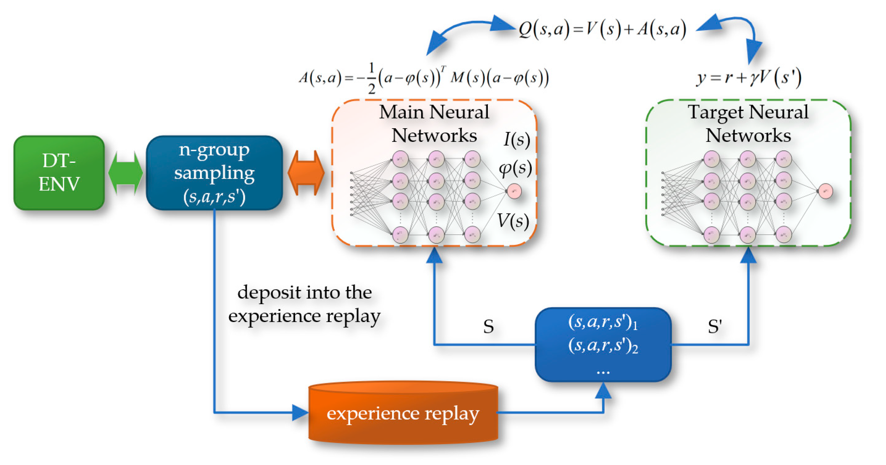
Figure 17.
(a)The feedforward neural network; (b) The network of the DQN-NAF algorithm.
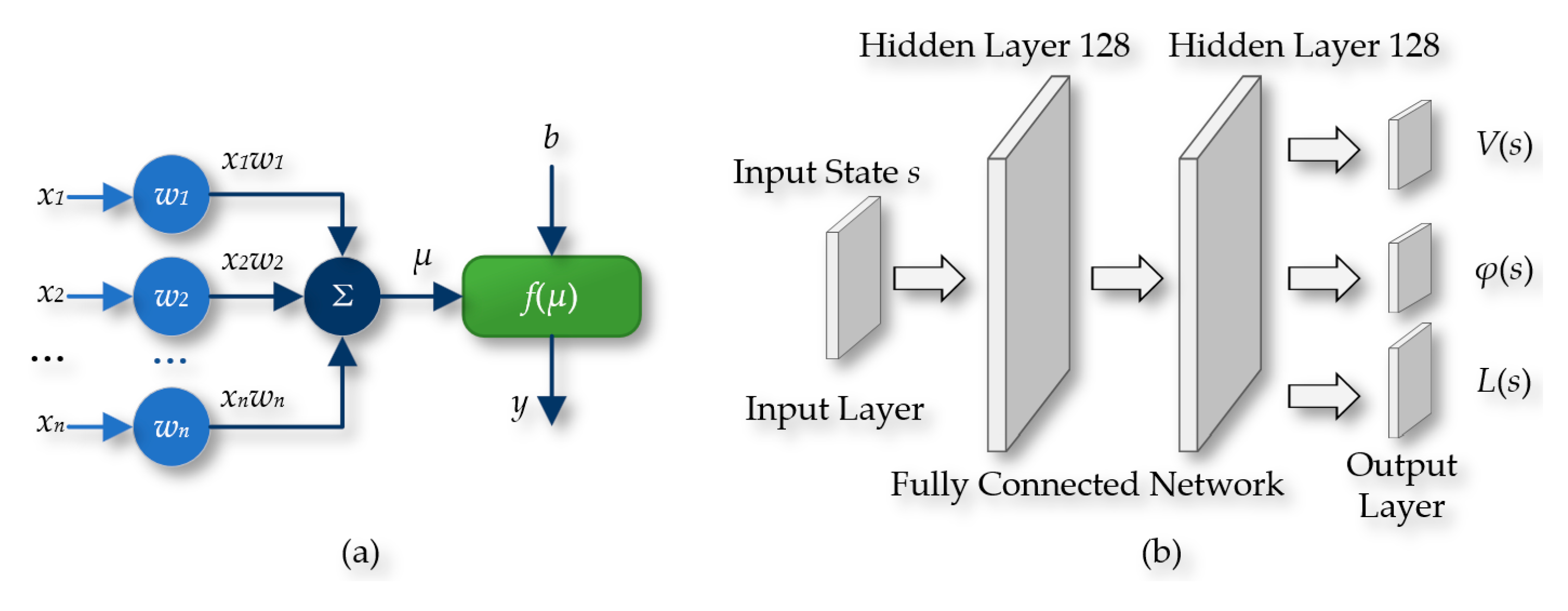
Figure 18.
The schematic of the Deep Deterministic Policy Gradient (DDPG) algorithm.
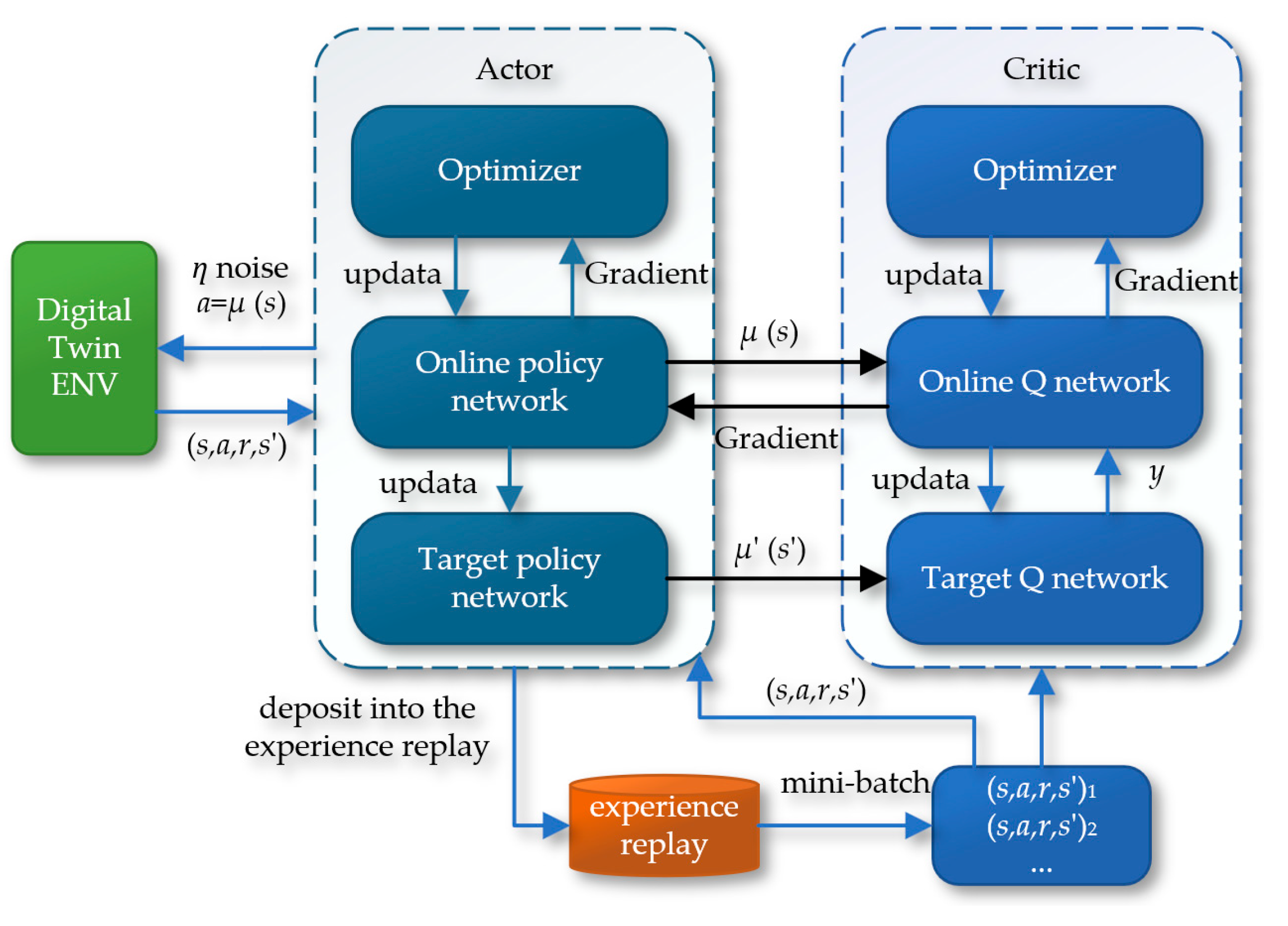
Figure 19.
The neural network of the DDPG algorithm: (a)The Actor; (b) The Critic.
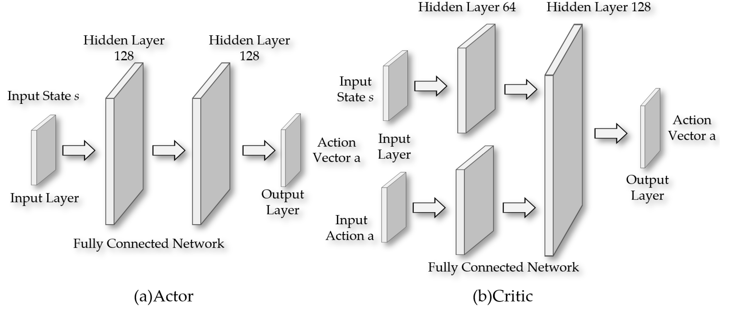
Figure 20.
The Interaction Between RL Algorithm and ML-Agents Software.
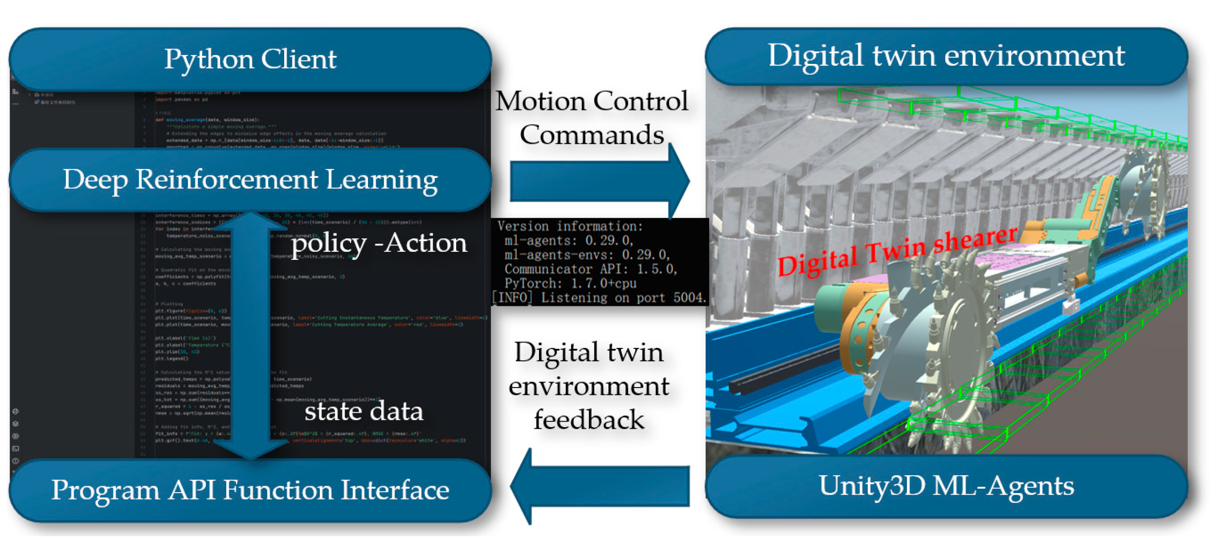
Figure 21.
The Principles of Reinforcement Learning Environment Construction.
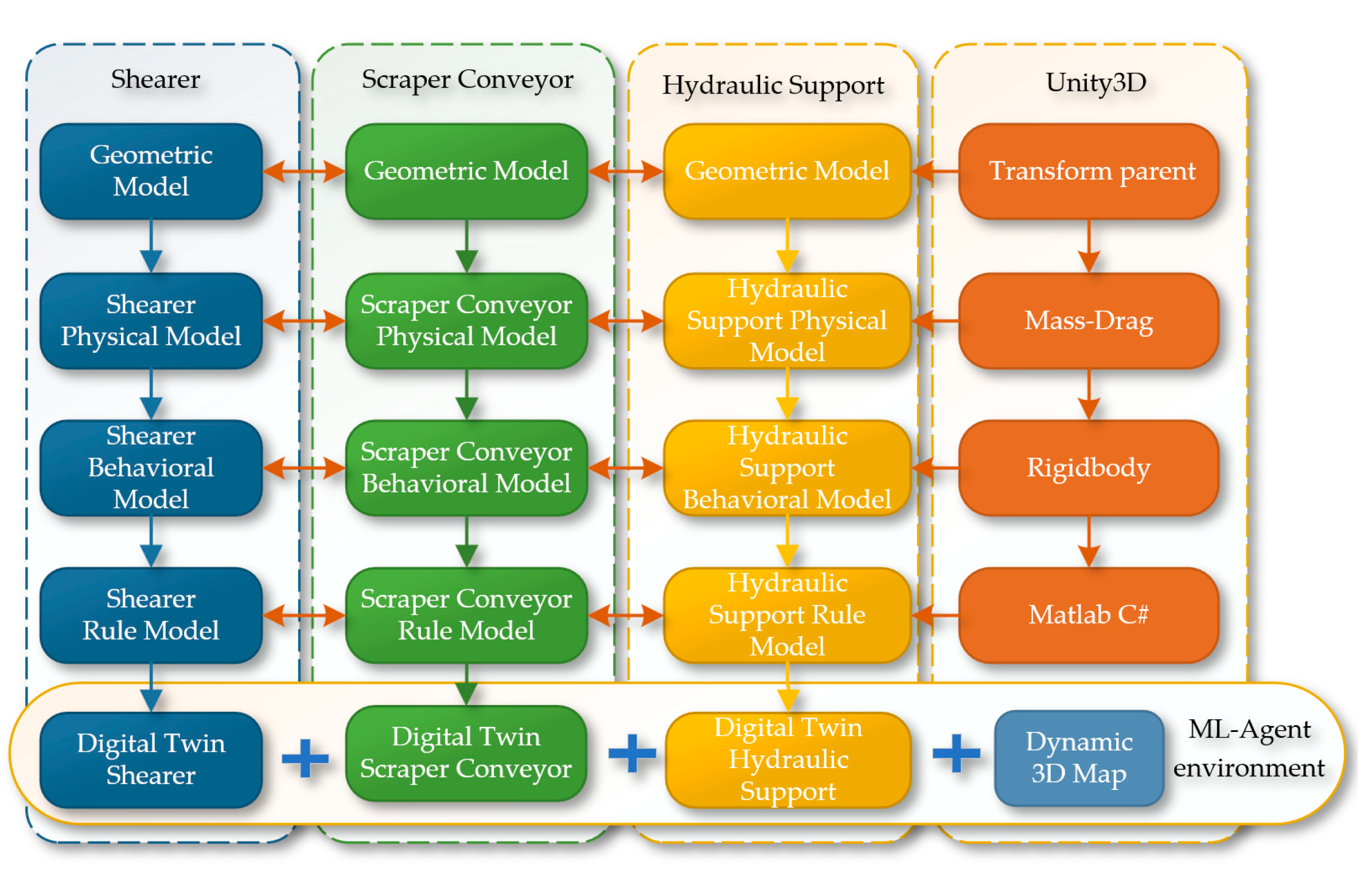
Figure 22.
The principle of the gravity Physical Engine Functioning.
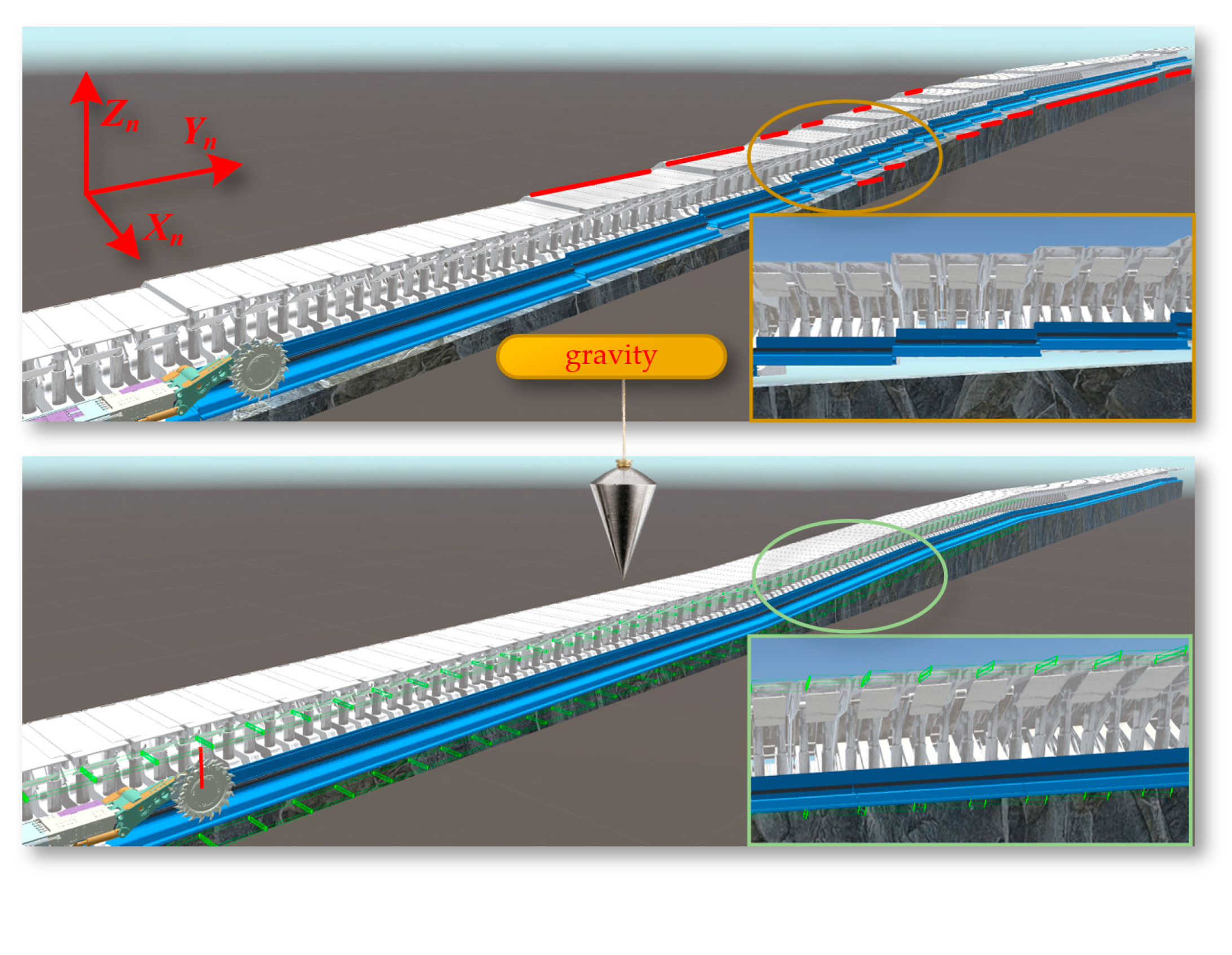
Figure 23.
The 3D Coal Seam Model.
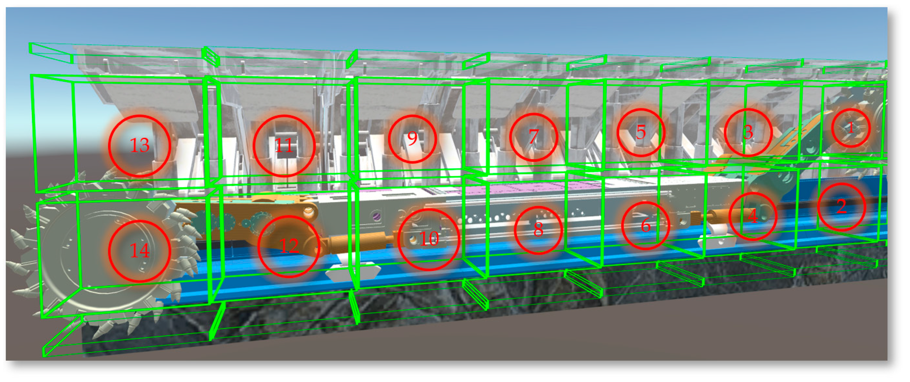
Figure 24.
The curve of the coal seam roof at the Workface.
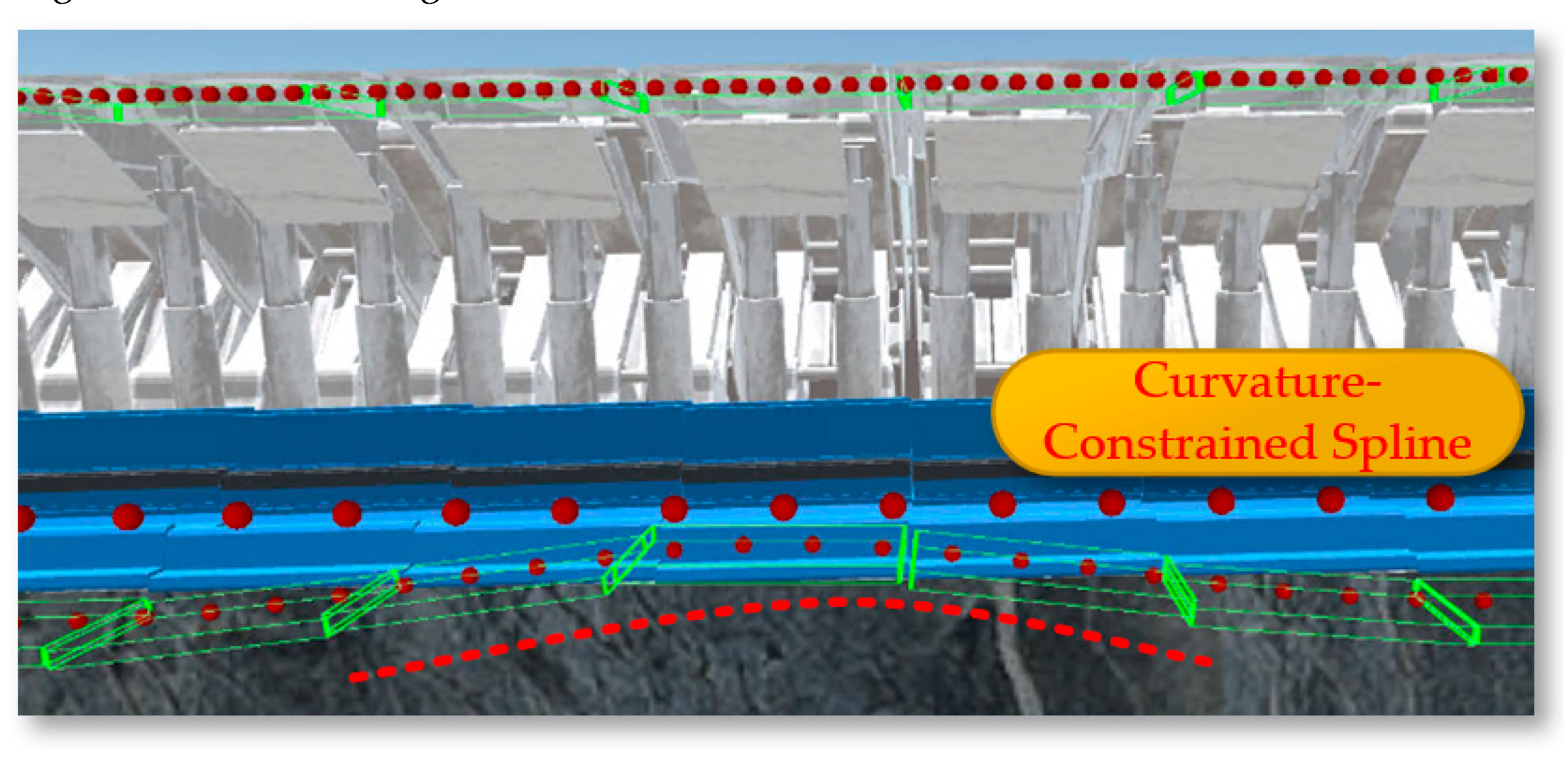
Figure 25.
The structural relationships of the shearer.
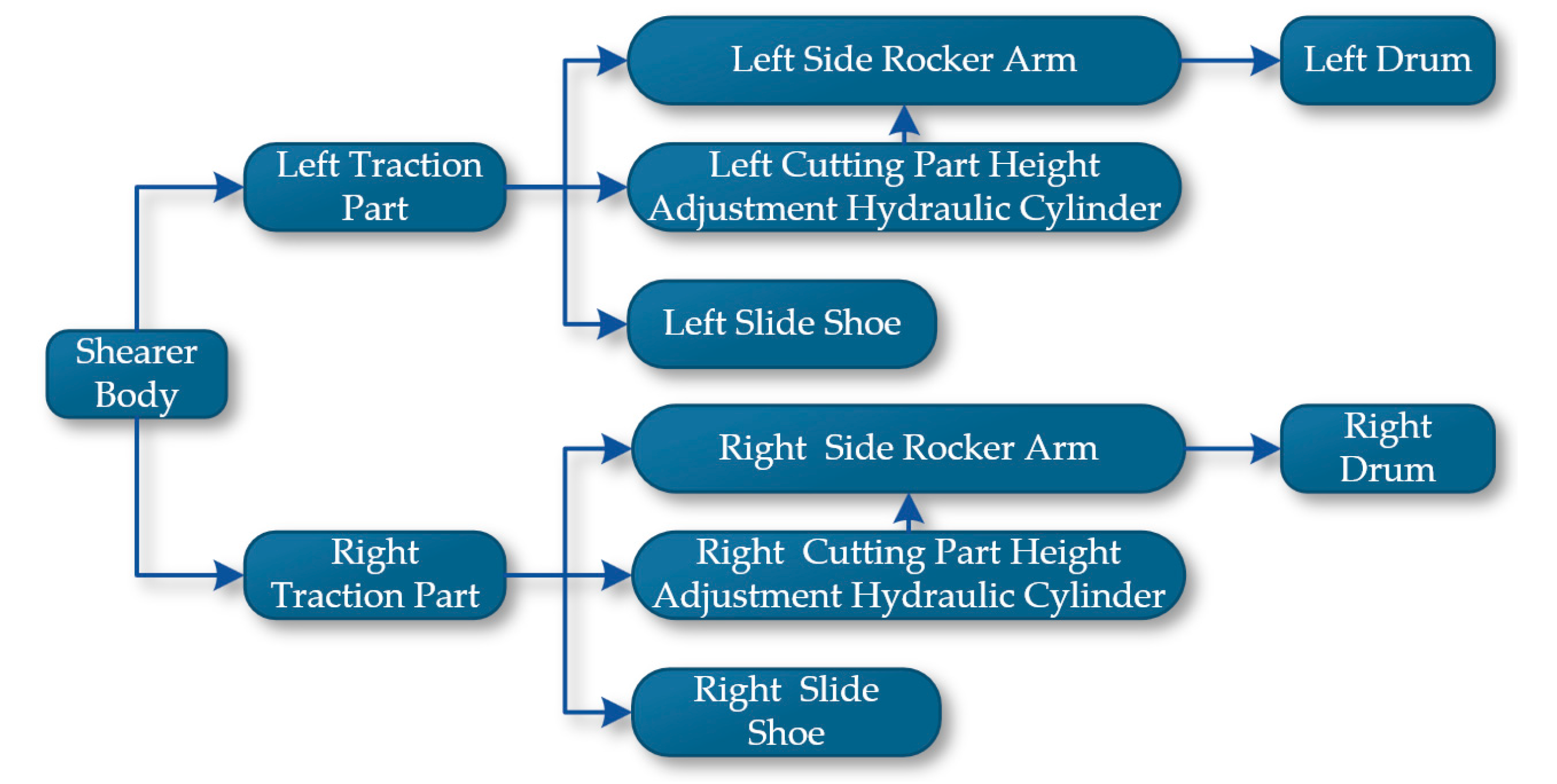
Figure 26.
The Configuration of the collider: (a)The BoxCollider; (b) The left CapsuleCollider; (c) The right CapsuleCollider.
Figure 26.
The Configuration of the collider: (a)The BoxCollider; (b) The left CapsuleCollider; (c) The right CapsuleCollider.
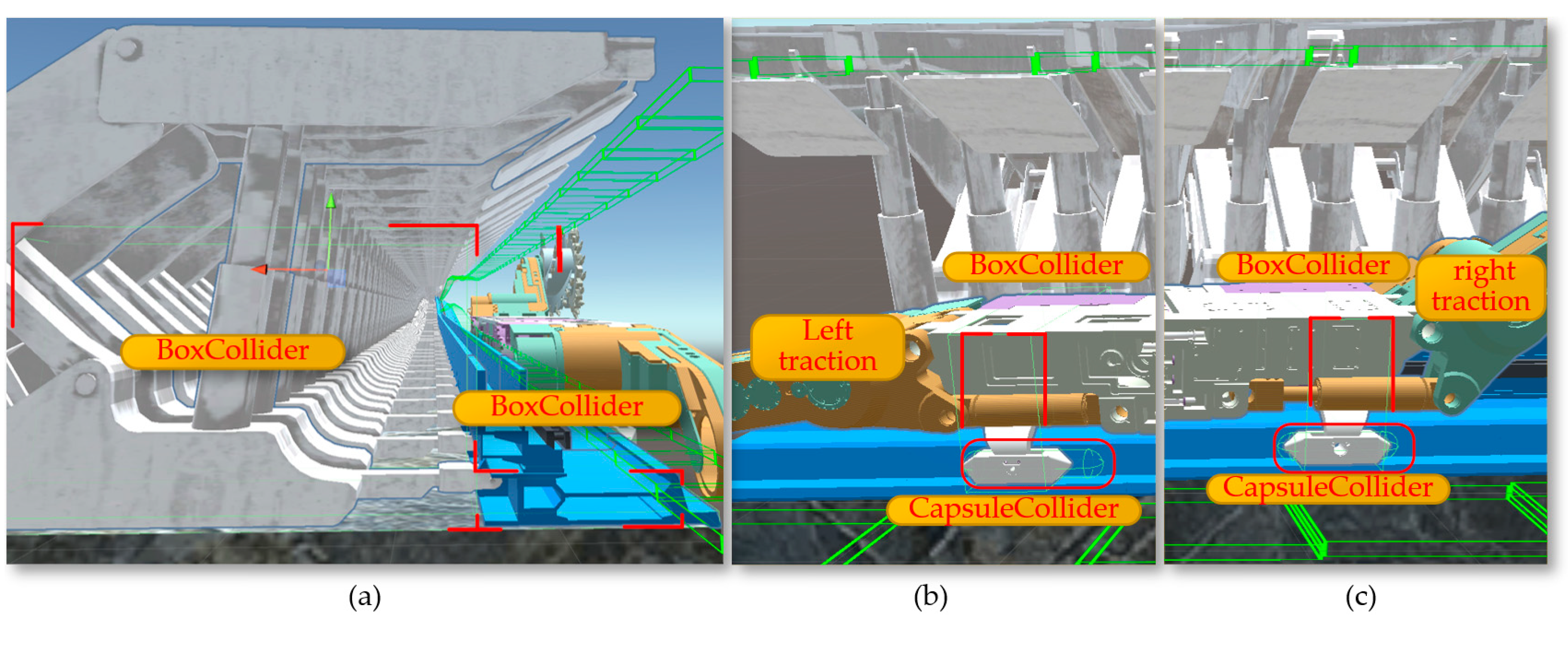
Figure 27.
The rotation of the shearer's drum: (a)The angles θ1; (b) The angles θ2.
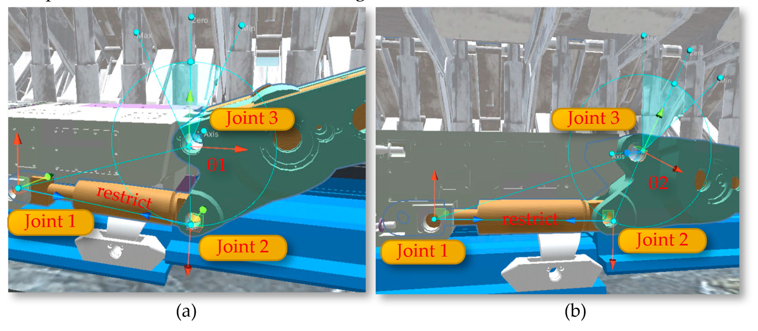
Figure 28.
(a)The Joints Configuration of Digital Twin hydraulic supports; (b) The state of the hydraulic supports after being lifted.
Figure 28.
(a)The Joints Configuration of Digital Twin hydraulic supports; (b) The state of the hydraulic supports after being lifted.
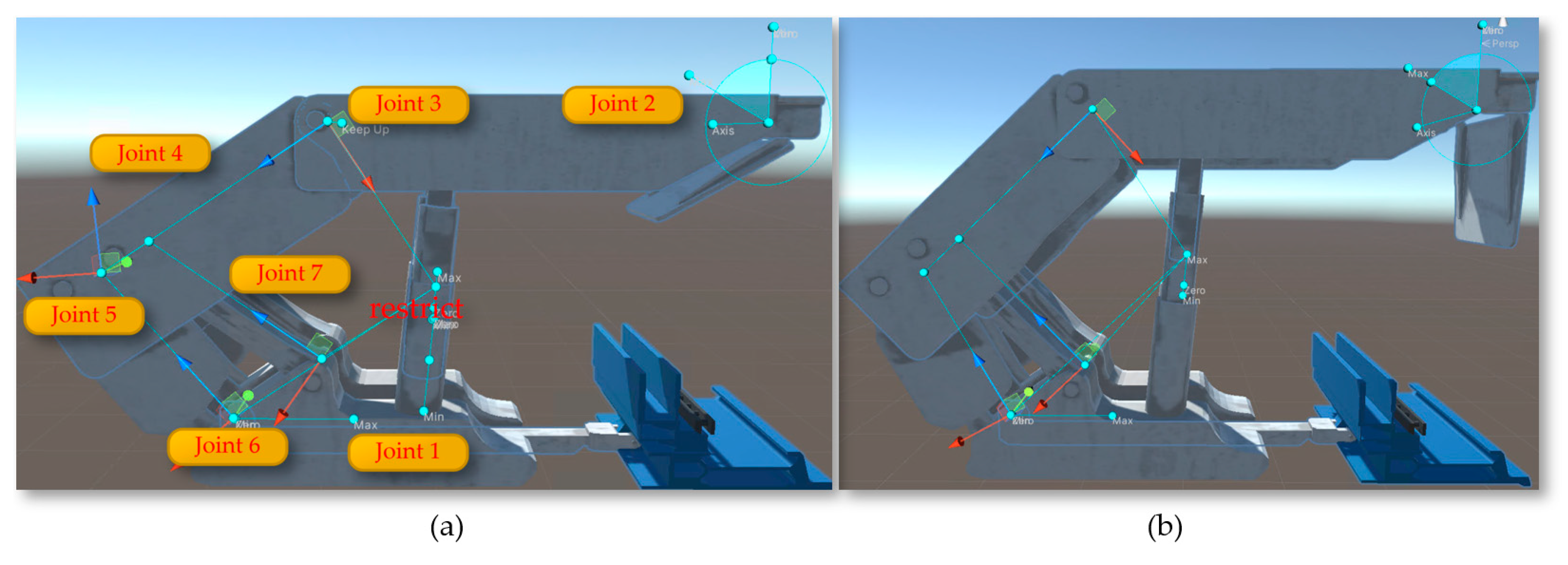
Figure 29.
The S-shaped bend of the scraper conveyor.
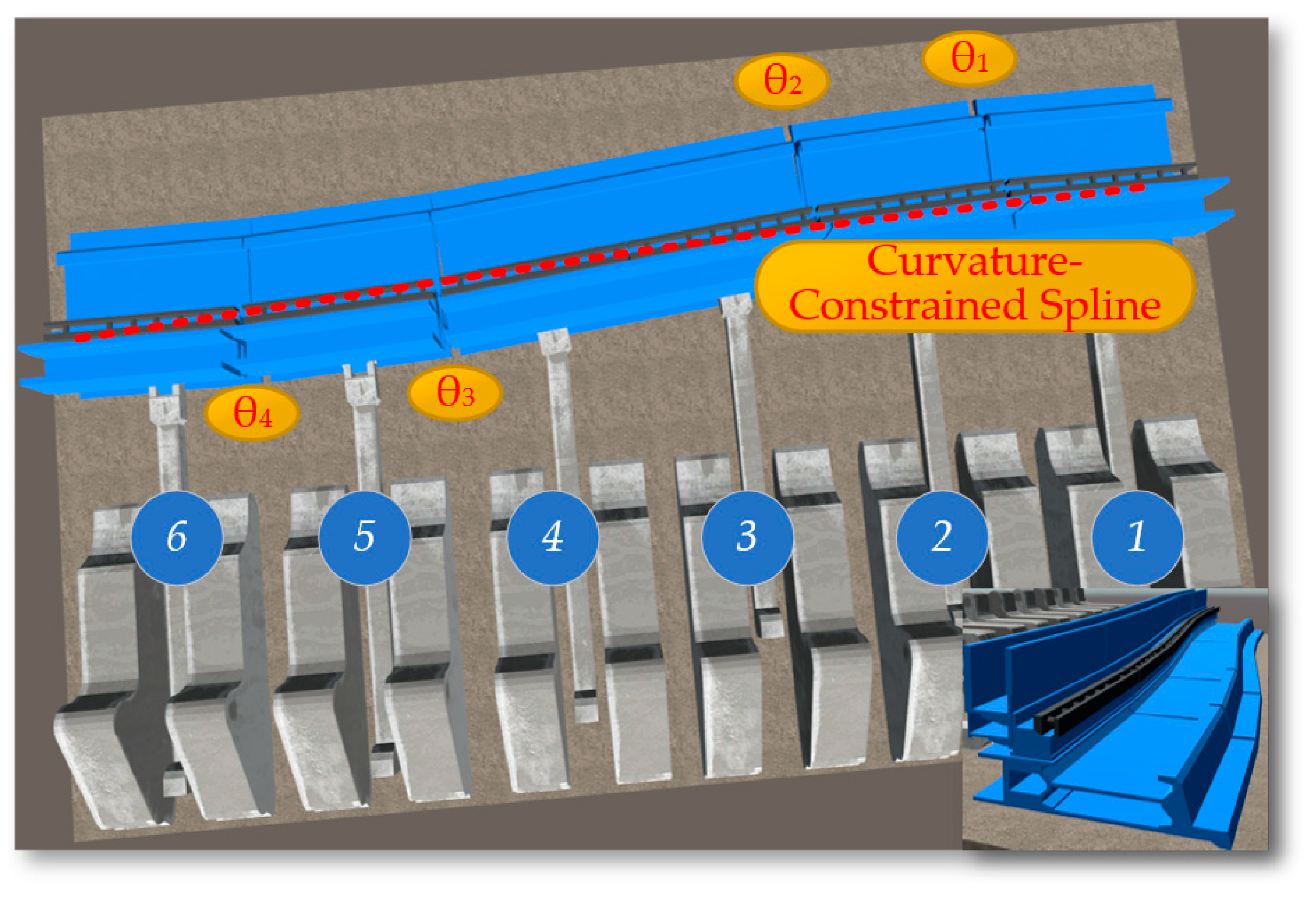
Figure 30.
The Scraper conveyor varies with the undulation of the coal seam.
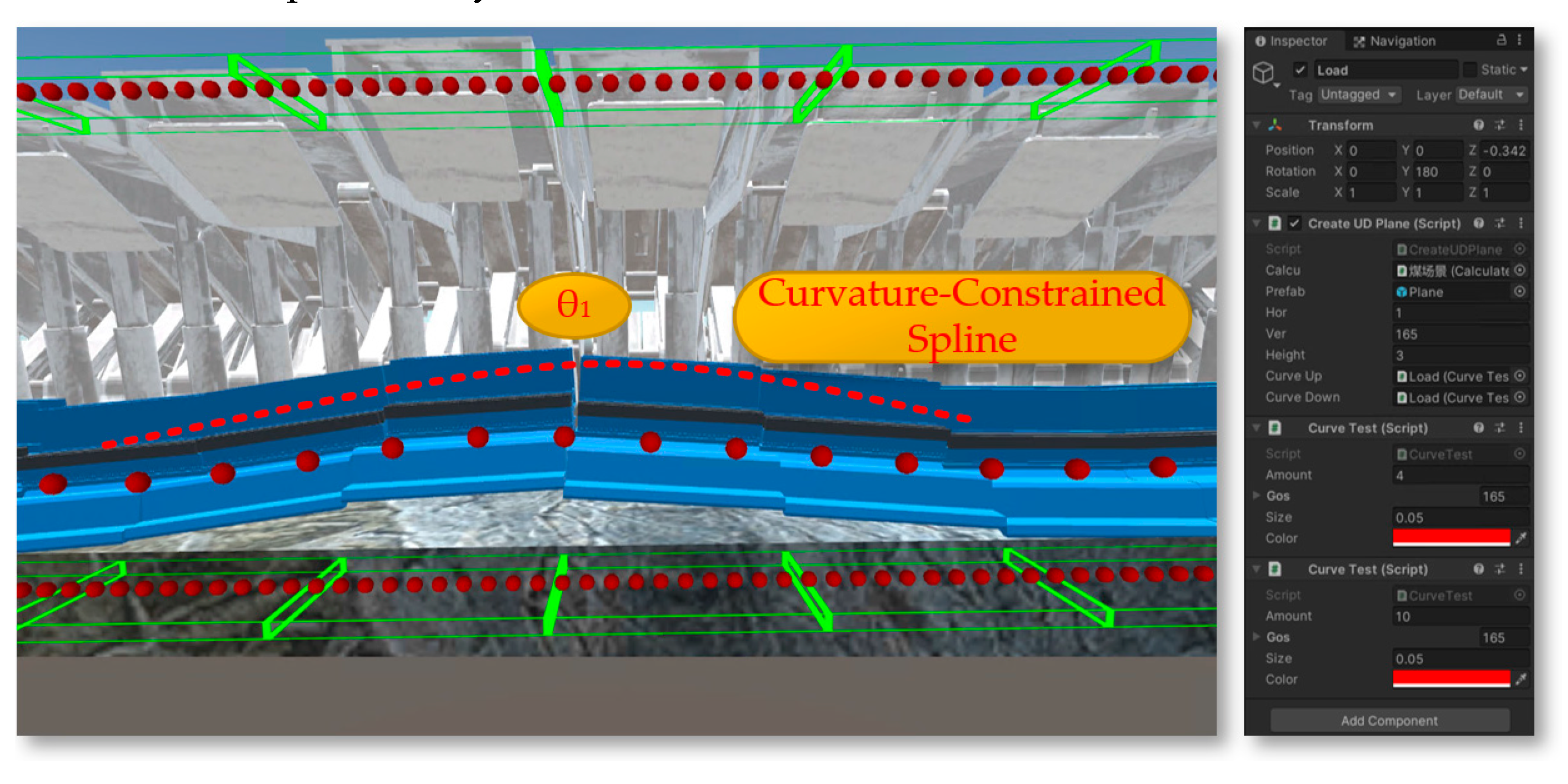
Figure 31.
The towing target and cutting task setting of the shearer.

Figure 32.
The environment for the shearer drum top and bottom tracking task setting.
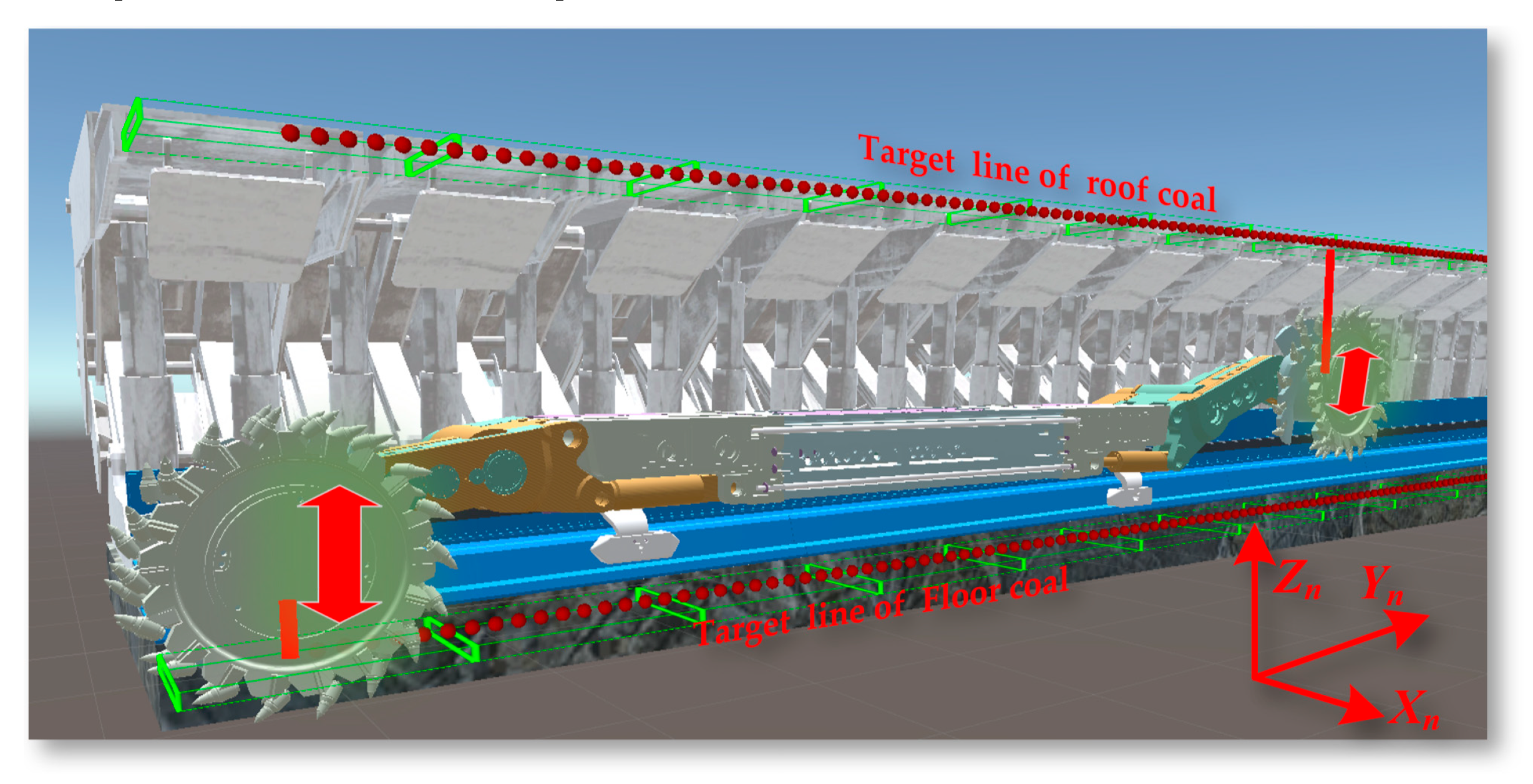
Figure 33.
The ML-Agents four-scene parallel accelerated training.
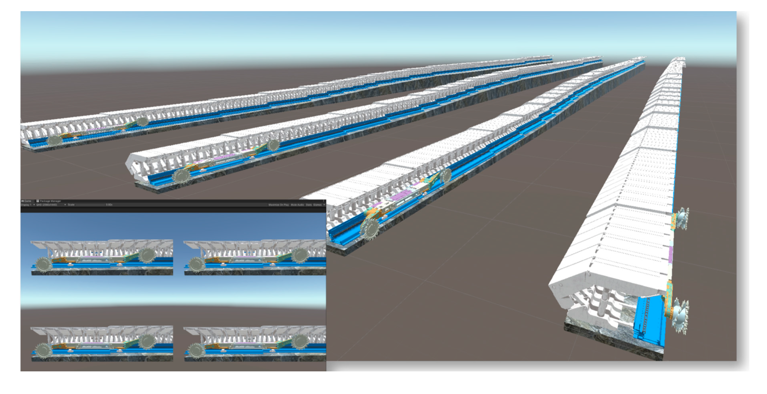
Figure 34.
The Environment/Cumulative Reward_hist: (a)The DQN-NAF; (b) The DDPG.
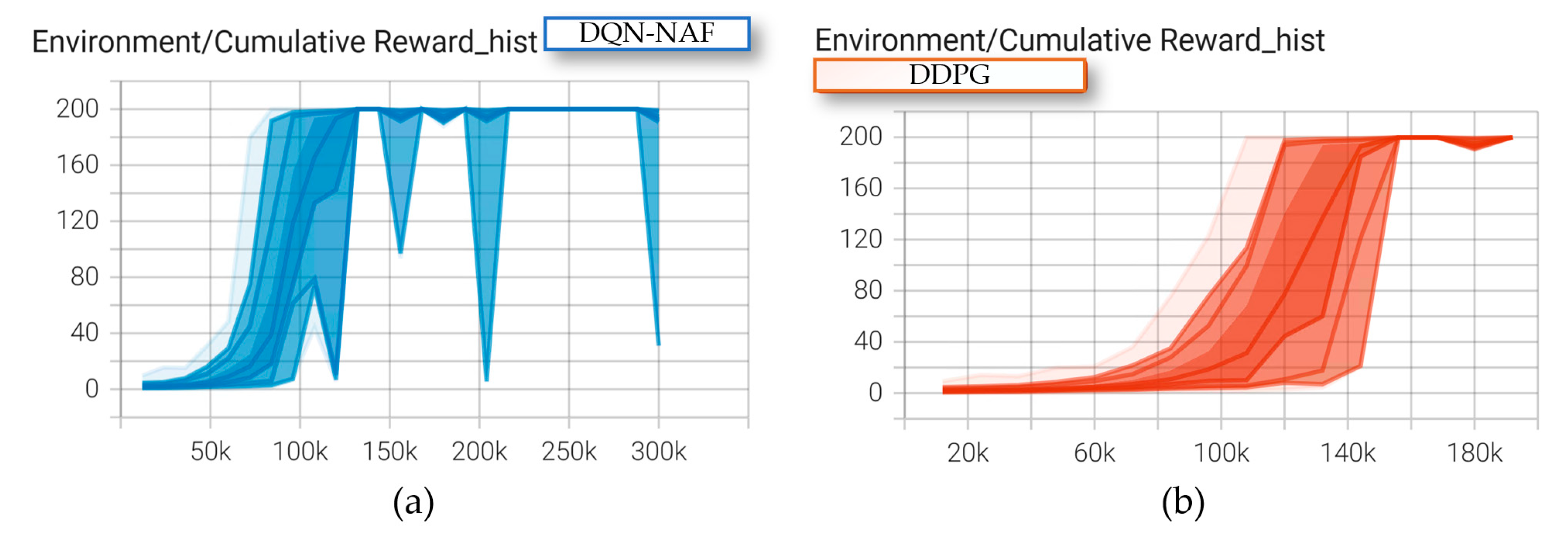
Figure 35.
The DQN-NAF and DDPG Algorithm Performance Comparison: (a)The Policy Loss; (b) The Cumulative Reward; (c) The Value Loss.
Figure 35.
The DQN-NAF and DDPG Algorithm Performance Comparison: (a)The Policy Loss; (b) The Cumulative Reward; (c) The Value Loss.
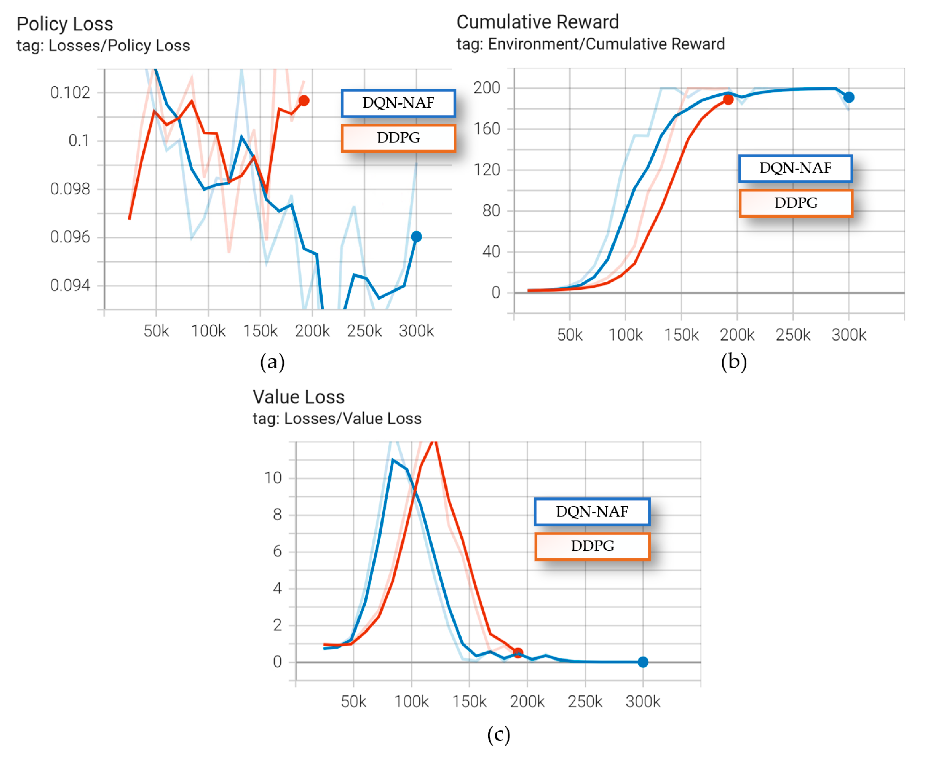

Table 1.
DQN-NAF algorithm pseudocode.
| DQN-NAF algorithm |
|---|
| 1: Initialize the online Neural Network Qπ and Target Neural Network Qπ'. |
| 2: For episode = 1 to M do |
| 3: Initialize action exploration noise ƞ. |
| 4: While the state has not reached a terminal state do |
| 5: Input the state into the online Neural Network Qπ, select action a = φ(s) + ƞ. |
| 6: Agent performs action a, receives immediate reward r, and the environment state transitions to s'. |
| 7: Store sampled experience (s, a, s', r) in the experience pool. |
| 8: If the data in the experience pool exceeds the size of the training batch |
| 9: Sample (s, a, s', r) from the experience pool. |
10: Input the action and state into the online Neural Network Qπ to obtain the diagonal of triangular matrix I(s) being positive, action vector φ(s), and state value V(s), obtaining 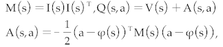
|
| 11: Input state s' into the Target Neural Network Qπ' to obtain the value V(s') and y = r + γV(s'). |
| 12: Use the mean squared error function between Qπ and y to update the parameters of the online Neural Network using regression method. |
| 13: With σ being a coefficient less than 1, gradually update the parameters of the online Neural Network towards the Target Neural Network: |
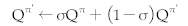
|
| 14: End if |
| 15: End while |
| 16: End for |
Table 2.
DDPG algorithm pseudocode.
| DDPG algorithm |
|---|
| 1: Initialize online Network parameters θQ and θμ for Critic and Actor. |
| 2: Initialize Target Network parameters θQ' = θQ and θμ' = θμ for Critic and Actor. |
| 3: For episode = 1 to M do |
| 4: Initialize action exploration noise ƞ, and state s. |
| 5: While the state has not reached a terminal state do |
| 6: Input the state into the Actor's online Neural Network, select action a = μ(s) + ƞ. |
| 7: The Agent performs the action a, receives immediate reward r, and the environmental state transitions to s'. |
| 8: Store the sampled experience (s, a, s', r) in the experience pool. |
| 9: If the data in the experience pool exceeds the training batch size |
| 10: Sample (s, a, s', r) from the experience pool. |
11:
Use the mean squared error loss of Q(s, a) and the target function 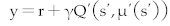 to update the parameters of the Critic’s online Neural Network. to update the parameters of the Critic’s online Neural Network. |
12: Use 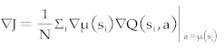 to update the Actor's Target Network. to update the Actor's Target Network. |
13: Update the Target Neural Networks of both the Critic and Actor, with σ being a coefficient less than 1: 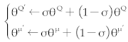
|
| 14: End if |
| 15: End while |
| 16: End for |
Disclaimer/Publisher’s Note: The statements, opinions and data contained in all publications are solely those of the individual author(s) and contributor(s) and not of MDPI and/or the editor(s). MDPI and/or the editor(s) disclaim responsibility for any injury to people or property resulting from any ideas, methods, instructions or products referred to in the content. |
© 2024 by the authors. Licensee MDPI, Basel, Switzerland. This article is an open access article distributed under the terms and conditions of the Creative Commons Attribution (CC BY) license (http://creativecommons.org/licenses/by/4.0/).
Copyright: This open access article is published under a Creative Commons CC BY 4.0 license, which permit the free download, distribution, and reuse, provided that the author and preprint are cited in any reuse.


