Submitted:
24 July 2024
Posted:
26 July 2024
You are already at the latest version
Abstract
One of the relevant goals in forging technologies is simplifying the existing process and developing new processes that can retain the original or very close to the original dimensions and billet shape after the end of the deformation cycle. This study attempts to develop a forging equipment design that provides alternating cyclic loading; the alternate cyclic forging (ACF) method is proposed. To preliminary evaluate the ACF and study the plastic deformation behavior, numerical simulation via finite element modeling (FEM) was conducted using DEFORM-3D. The main attention was paid to the metal flow characteristics, effective strain and stress distribution, and the forging load. The ACF results in non-uniform metal flow with the formation of diagonal and vortex flows were demonstrated. Maximum effective strains and stresses zones are localized at two points of the billet contact with the surface of the tooling container and at two points of the interface between the punches. It was also assumed that reducing the contact area between the punch and the billet using separate semi-cylindrical punches can reduce the forging load. Preliminary finite element analysis (FEA) results of the proposed process after four successive steps of the deformation cycle confirmed the feasibility of its general implementation.
Keywords:
finite element analysis (FEA)
; alternate cyclic forging (ACF)
; metal flow
; effective strain
; effective stress
; forging load
1. Introduction
The progress in the metal forming, achieved over the past few decades, both from experimental and numerical viewpoints, has naturally led to an increase in interest in the engineering development of improved and non-conventional forming methods. Gronostajski et al. [1] reviewed the development trends of selected metal forming methods, which have been the subject of research and implementation in industry over the past 10 years. It was noted that the creation of improved metal materials with specific functional properties was the main driving force behind the progress of metal forming in the last decade, and an essential role was played by robotization and automation of the industry. Li et al. [2] underlines the promising potential of applying electricity-assisted forming, ultrasonic vibration-assisted and electromagnetic field-supported forming as a supplement to mechanical force and as an alternative to the thermal effect on the material in conventional processing technologies. Hafenecker et al. [3] considered the prospects of hybrid technologies based on a combination of forming with additive manufacturing as a way to solve the problem of mass production of individual or customized parts. Pradeep Raja & Ramesh [4] discussed the key issues and the role of microforming processes in the production of miniaturized micrometallic components and parts.
Nowadays, alternative forming methods, collectively called severe plastic deformation (SPD), are currently the most popular techniques. Their advantages lie in the possibility of obtaining increased performance properties in many industrial metal materials compared to traditional forming methods due to more intensive refining of grains down to nanocrystalline scales [5] by creating more efficient and often complex deformation modes. Segal [6] emphasized that these modes can range from pure shear to simple shear, with pure shear being preferred for forming processes and simple shear being optimal for modifying and intensively refining the material structure. In both cases, it is believed that to obtain metal materials with improved properties compared to traditional forming, it is necessary to impart an equivalent strain to the material above a certain threshold. The authors of the review [5] believe that an equivalent strain above 6 is such a threshold. Although they admit that there is debate about the actual strain threshold since in some materials SPD-specific microstructural evolution is achieved at strains below this threshold, and in some materials, on the contrary, evolution continues to occur even at much higher values of shear strain. This debate is further aggravated by the fact that when the desired strain threshold is reached in some materials, (a) softening rather than hardening is possible, or (b) possible excessively large values of the average stress generated by large strains, without additional thermal effects, will ultimately lead to excessive saturation of the material in a steady state, accompanied by critical consumption of the plasticity resource and an increase in the likelihood of internal and external defects in the material. Moreover, many authors believe that only those methods that have the ability to preserve or return the original or very close to the original dimensions or shape of the billet after each deformation cycle, consisting of one or more deformation passes (or steps), should be classified as SPD. While other methods, such as asymmetric rolling [6,7] and alternate extrusion (AE) [8] should be considered separately, despite their ability to create shear strains, although a recent review by Bagherpour et al. [9] classifies these processes as SPD methods. The ability to maintain the billet shape is considered one of the main features that distinguish SPD methods from conventional forming methods, since the latter are characterized by an irreversible change in dimensions after each deformation cycle and the maximum possible level of accumulated strains is limited by the maximum possible degree of strain, for example, extrusion ratio, thickness reduction by rolling, which are often not sufficient for intensive refining of grains; and hence, for obtaining the desired increase in properties. Such SPD methods as equal-channel angular pressing (ECAP) [10], twist extrusion [11], cyclic extrusion-compression [12], cyclic closed-die forging (CCDF) [13], multiple isothermal forging (MIF) [14], repetitive forging (RF) [15], multi-axial incremental forging and shearing (MAIFS) [16], accumulative roll-bonding [17] have the ability to maintain the shape of the billet and many of them are considered classical SPD methods. Therefore, when developing new SPD methods, this ability of the method being developed should be considered.
Analyses [2,3] and other available sources on the issue of SPD development revealed that most of the currently known SPD methods are based on angular (ECAP) and direct/indirect extrusion (~60%), and the share of forging-based processes is only ~12÷15%. In the first two cases, the strain parameters or extrusion ratio can reach much higher values than in forging and rolling, which makes them attractive to researchers. However, from a technological standpoint, extrusion methods have essential disadvantages. For example, such processes as twist extrusion [11], elliptical cross-section spiral equal-channel extrusion [18], vortex extrusion [19], variable cross-section direct extrusion [20], twist channel angular pressing [21], planar twist channel angular extrusion [22] and other similar process modifications have a complex geometry of the extrusion channel part, which not only complicates the manufacture of dies, but also intensifies the rate of its wear since the metal flow in these parts is complicated and leads to a significant increase in contact friction, and hence, extrusion pressure. In addition, many of the above processes fail to ensure the preservation of billet dimensions or may require additional operations, such as backpressure, which reduces productivity since its implementation is complex in itself. To some extent, this drawback is also characteristic of such ECAP modifications as non-equal channel angular pressing [23], double change channel angular pressing [24] and forward extrusion-ECAP [25].
It should be noted separately that the interpretation of the SPD mechanics is not entirely correct, primarily the specifics of the distribution of stresses and strains, and metal flow, led to the proposal of SPD methods that either to some extent simulate shear, or are completely mistakenly recognized as methods that create shear. The problem was convincingly presented by Segal [6], who highlighted such processes as equal-channel angular drawing, constrained groove pressing, equal-channel angular swaging, simple shear extrusion, pure shear extrusion, and equal channel forward extrusion as examples of this problem.
In the case of direct/indirect extrusion based methods, it is also necessary to consider that since in such processes, despite changes in the geometry of the extrusion channel, the technological principle of conventional extrusion is preserved, there may be disadvantages characteristic of conventional direct/indirect extrusion methods, for example, low extrusion speeds for defect-free strain of some metal materials, the inevitable extrusion discard, anisotropy of properties due to the strain in homogeneity, much smaller dimensions and shapes of the original bulk billet compared to forging, or difficulties in scaling. Of the methods considered, Segal’s classical ECAP [6] is least characterized by the considered disadvantages, which, along with the creation of an optimal deformation mode, is one of the reasons for the greatest popularity of this method and as a subject of study by many authors and a basis for creating modifications of the method, and particularly as the method with the greatest potential for commercialization [26].
As mentioned above, methods based on forging principles can effectively solve scaling difficulties owing to their inherent ability to plastically deform bulk billets. In this regard, several methods should be noted that are based on the principles of open and closed die forging processes with the ability to create large strains in the billet material while maintaining its dimensions. Previously mentioned processes with a similar deformation principle such as CCDF [13], MIF [14], RF [15] and MAIFS [16] are widely used in academic research and are promising candidates for industrial application. Among them, the MIF process is based on open-die forging, and the other three are based on closed-die forging. The principle of all four methods is based on the accumulation of large strains in the material by cyclic non-monotonic loading. Analysis of various publications highlights the significant technical advantages of these methods such as simplicity, low cost and applicability to materials with varying degrees of plasticity characteristics, under various thermal and kinematic conditions. At the same time, there is a lack of research into these methods applicable to aluminum alloys of various nomenclature series from 1xxx to 9xxx, which are widely used in such important industries as the automotive and aerospace industries [27,28,29], construction engineering [30], and also represent significant interest in engineering development of metal matrix composites [31,32], cryogenic processing [33], and additive manufacturing [34] because of such remarkable specific properties as an optimal balance of strength and weight, increased corrosion resistance, good formability and casting properties, excellent electrical and thermal conductivity, and environmental friendliness. The main production process for producing aluminum alloys is casting; and according to [28], its predicted share in production by 2030 will amount to 56.14%. Although casting processes make it possible to obtain rather complex shapes, it is known that in terms of such crucial indicators as saving material and labor, the possibility of obtaining pure or close to pure shapes of the surface of processed materials and giving them operational properties by creating effective deformation modes they are significantly inferior to forging processes.
To substantiate the efficiency of processes, the analysis of SPD mechanics, primarily the analysis and evaluation of such basic mechanical parameters as stress and strain, their distribution, and flow characteristics in the material, play a particularly significant role [6]. For this kind of analyses, most metal forming processes use various techniques: slip line field [35,36], numerical simulation via finite element modeling (FEM) [37,38], physical modeling using thermo-mechanical simulators [39,40] and model materials [41,42]. Numerical simulation via FEM is the most productive method among them, which is currently implemented using advanced and powerful computer simulation programs such as DEFORM-3D, based on the iterative solution of discretized nonlinear algebraic equations. In turn, they are converted from a general equation obtained using the variational method to the basic equations of rigid viscoplasticity [38,43]. These equations are consistent with the basic conditions and/or assumptions of plastic deformation and include almost all the main parameters that describe the behavior of rigid-viscoplastic bodies in metal forming processes: the parameters of stress, strain, speed, force, and temperature.
The present study aims to present and scientifically evaluate the potential of the alternate cyclic forging (ACF) method, which is simple and capable of maintaining the original or very close to the original dimensions and shape of the billet after the end of the deformation cycle, through finite element analysis (FEA) of stress and strain distribution, flow characteristics, forging loads exemplified by 6061-T4 aluminum alloy.
2. Materials and Methods
2.1. Process Principle
The schematic of the ACF process is shown in Figure 1. The simplified design of the device consists of a container in the cavity of which there is a cylindrical billet of diameter D and height H, and four semi-cylindrical punches of the same size. One full cycle of the ACF process consists of four steps (or passes), alternately implemented by punches. Steps 1 and 3 are performed with the same stroke of the first and second punches h1, and at the same time the fourth and third punches, located diagonally opposite or pointwise are inverted relative to the first and second punches, respectively, are not fixed, and the other two punches are fixed as shown in Figure 1. As a result of this, the formed flow forces excess material into the cavity of the non-fixed punches at a distance h2, which in Steps 2 and 4 is pressed back by the fourth and third punches, respectively, returning the original or as close as possible to the original dimensions billets. In this case, during Steps 2 and 4, all three punches except the active one remain fixed. The ACF is performed without turning or pulling the billet out of the container cavity.
2.2. Numerical Simulation Procedure
In this study, the commercial FEM code DEFORM-3D was used to numerically simulate the ACF process. The main parameters of the finite element analysis (FEA) in DEFORM-3D are given in Table 1. To avoid unwanted shearing and excessively large values of the h2 parameter, in this study it was decided to choose the maximum stroke value of the first and second punches h1 ~ 0.25H ~ 12 mm. After simulating Steps 1 and 3, it was revealed that h2 ~ 17 mm. Constant shear friction is assumed between the billet and parts of the tooling with a coefficient of 0.12, characteristic of steel tooling in cold forming processes. The process was simulated at a constant speed of the punches v = 1 mm/s.
Upon the simulation, the DEFORM-3D post-processor analyzed the stress and strain distribution characteristics and the material flow behavior after each of the four process steps, and the corresponding images of the parameters in the XZ plane were obtained. For an objective comparison of parameters by steps, the range (maximum and minimum values) of the scales of the analyzed parameters was chosen to be the same for all four steps.
The stress and strain distribution was monitored and analyzed by nine characteristic points P1÷P9 moving during the deformation process, marked in the XZ plane of the original billet, the coordinates of which are shown in Figure 2. During the process steps, the coordinates of the points change and to continue the analysis in the DEFORM-3D post-processor, the changed coordinates were obtained in the form of a .DAT file after each step, with the exception of the last fourth, which were used as tracking points for subsequent steps.
3. Results and Discussion
3.1. Metal Flow
Figure 3 shows the ACF velocity field distribution. Under conditions of alternating load, it was noticed that the speed of the material particles varies significantly, and the main flows with the highest speed are formed between diagonally located punches.
In all four steps, three separate flows or localized flows are observed including the main diagonal flow and two flows formed conventionally above and below the main flow. As can be seen from Figure 3, conditional boundaries of the main flow and two other flows are located between points A and B, A' and B'. Here A and A' are the vertex points of the main active punch and the diagonally located non-fixed punch, respectively, and B and B' are the lateral points of the metal contact with the container surface, which are located approximately in the center of this surface. These same points are also the conditional boundaries of the interface and three zones of the main flow: a zone with a diagonal flow and two zones with a non-diagonal flow, conditionally located on both sides of the first zone. The conditional interface boundaries between these zones are located between points A and B', A' and B, i.e., the zone conditionally limited by the rectangle ABA'B' is a zone of diagonal flow. Approximately triangular zones located in separate steps above and below segments AB' and A'B represent zones of non-diagonal flow, where, under compression load conditions, the vectors of their velocities or the direction of their flow are parallel Z axis. As can be seen from Figure 3(a) and (c), this division of the main flow into zones is facilitated mainly by the diagonality or eccentricity of plastic deformation due to the load of the first and second active punches, while the third and fourth punches are not fixed or passive, and the material particles tend to move toward their free cavity. The behavior of flows at Steps 2 and 4 can be considered similar, where (see Figure 3(b) and (d))because of the loading of the fourth and third active punches, material particles tend to move into the free cavity or fill the cavity formed by the first and second punches in Steps 1 and 3. Noteworthy, along with the geometric parameters and load peculiarities in the ACF, the friction conditions between the tooling elements and the billet material are also of no small importance. Figure 3(a) and (c) clearly shows that during the strokes of the first and second active punches, the metal particles, which are located under the second and first inactive punched, respectively, and fixed in Steps 1 and 3, having received radial thrust from the main diagonal metal flow generated by the active punches, flow into the zone limited by the surfaces of the container, active and inactive punches, resulting in friction-created vortex flows, marked in the figure with a red circle, above the conditional segment AB. Liu et al. [44] also observed such vortex flows in AE. Figure 3(b) and (d) demonstrate that in the zones under the conditional segment AB, vortex flow nuclei began to form, and we can conclude that if we continue to move the fourth and third active punches similarly to Steps 1 and 2, distinct vortex flows will also be formed in these zones.
Many authors also report similar vortex flows when studying various methods for plastic deformation. Kulagin et al. [45] observed such flows under high pressure torsion of a bimetallic laminate and noted that vortex flows were caused by plastic instabilities because of local locking of shear strain. Beygelzimer et al. [11] observed vortex flows with a large deformation gradient in the twist extrusion process and came to the conclusion that the kinematic features of such flows enabling to stretch and mix metal particles open up opportunities for the study and formation of novel microstructures. The authors also provide examples of the successful use of vortex flow features to obtain ultrafine-grained microstructures with good properties in Al, Cu and Ti alloys. The complex kinematics of vortex flows, regarding the rheology of the metal and friction conditions, was considered separately by the authors in [46]. Also noteworthy is the vortex extrusion method [19], where the tooling geometry is completely focused on creating vortex flows using their favorable capabilities in terms of the property-microstructure relationship. Therefore, we can preliminary summarize that the creation of vortex flows in the ACF, and alternation or change of directions of the main flow will make it possible to effectively form the necessary microstructure with optimal performance properties in the future.
3.2. Effective Strain
Figure 4 represents the effective strain distribution on a deformed billet in the ACF after each step.
The average values of effective strains in the XZ plane increase in steps and are equal to 0.380, 0.799, 1.220 and 1.730, respectively, and the increase is ~ 110.3% (from Step 1 to Step 2), ~52.7% (from Step 2 to Step 3) and ~ 41.8% (from Step 3 to Step 4). The proportions of effective strain in the ACF by strain value ≥ 0.5, 1.0, 1.5 and 2.0 are presented in Figure 5. It can be seen that the proportion of effective strains increases with each subsequent step and in the last considered step the XZ plane consists entirely of effective strains ≥ 0.5, and the proportions of strains ≥ 1.0 and ≥ 1.5 reach 82.14% and 35.53%, respectively.
Available friction forces, loading characteristics and plastic deformation in the ACF lead to non-uniform localization of deformation, similar to the “+” sign. Figure 4 shows that the zones of the greatest deformations are localized by the points of the billet contact with the container surface (points P6 and P7) and the “junction” points (interface) of the punches located between points P1 and P2, P3 and P4. This is also confirmed by changes in the effective strain values at points P1÷P7, shown in Figure 6. Changes in absolute and average values of effective strain in Figure 6(a) and 6(b) demonstrate that the maximum values of deformations are characteristic of points P6 and P7, followed by punch points P1÷P4, and the central point P5 corresponds to the minimum values of deformations. According to Figure 4, it is fair to state that if two points in the “junction” zone of the punches were additionally selected as the initial tracked points (Figure 2), the curves of these points and the nature of the change in the deformation values at these points would be similar to points P6 and P7. Since the ACF has the peculiarities of closed-die forging, i.e., plastic deformation occurs under conditions of a relatively rigid, limited cavity of the container, with each subsequent step the values and area of the localized deformation zone increase, which is confirmed by Figure 4, Figure 5 and Figure 6. In this case, the alternation of the punch loads leads to the fact that in subsequent steps, the zones of the least effective strains will be increasingly subject to the effects of plastic deformation, gradually experiencing higher deformations. This also applies to the central zone of the material around point P5, where the material experiences the least deformation. However, as Figure 6 shows, absolute and average values of deformations in these zones increase approximately linearly, reaching absolute values in the range of 1÷1.5 in the last fourth step.
The bands formed by the interface between two adjacent punches and the side points P6 and P7 are shear bands, as can be seen in the contrast maps of effective strains in Figure 4. It can also be concluded by the contrast maps that in the ACF, the material is subject to shear and normal strains as in the AE [44]. The level of strain intensity depends on the penetration depth (stroke of the active punch), and on the size of the non-fixed inactive punch, i.e. if the size (namely, the half-cylinder radius) of the inactive punch is smaller, the strain ratio will be greater, and therefore, the strain values will also be greater. In addition, the difference in size of two inactive non-fixed punches will create an additional axis or eccentricity to the billet axis, which further will intensify the diagonality of the flow and the shear component of the strain.
3.3. Effective Stress
Figure 7 representates the effective stress distribution on the deformed billet in the ACF after each step.
As in the case of effective strains, localization of stresses is observed at points P6, P7 and two opposite points of the interface between the punches. This localization can be explained by the conditions of strain in the container cavity, loads from the punches and the accompanying friction conditions, which limited plastic deformation, leading to high stresses and strains at all forging steps.
The average values of effective stresses in the XZ plane increase in steps and are equal to 288, 341, 353 and 392 MPa, respectively, and the increase is ~ 18.4% (from Step 1 to Step 2), ~ 3.5% (from Step 2 to Step 3) and ~ 11.0% (from Step 3 to Step 4). The proportions of effective stresses in the ACF based on stress values ≥ 90, 180, 270 and 360 MPa is presented in Figure 8. In all four steps, the proportion of effective stresses ≥ 90 and ≥ 180 MPa is above 90%, the proportion of effective stresses ≥ 270 MPa is above 65%. The proportion of effective stresses ≥ 360 MPa increases with each step and at the end (Step 4) reaches 91.9%. As a result, at the last step of the cycle, the proportion of all considered absolute stress values is above 90%.
Changes in absolute and average values of effective stresses by points for simulated conditions are shown in Figure 9 and Figure 10, respectively. All points in all steps showed a rapid increase in voltage at the ACF onset. Similarly, as in the case of effective strains, the maximum absolute values of effective stresses (stress localization) are characteristic of points P6, P7 and two opposite points of the boundaries of the punch interfaces, located between points P1 and P2, P3 and P4, respectively. Such high stress values at these points remain stable at all steps of the deformation cycle. After a sharp increase at the beginning, in the intermediate stage for all ACF steps, all points except one punch point at each step (point P2in Step 1, point P4in Step 2, point P1 in Step 3, and point P3 in Step 4) record a high effective stress. The reason for the short-term (0.2 s) drop in stress at point P2 from 213 MPa (at h1 = 10.8 mm) to 77.6 MPa (at h1 = 11 mm) is most likely a short-term weakening of the friction forces at this moment at the point and this drop is not critical, as already after 0.5 s (at h1 = 11.5 mm) the stress value increased by 162 MPa.Similar to the curve of absolute values of effective strains in Step 1, shown in Figure 6(a), here also point P2 is characterized by minimum stress values, particularly toward the end of the step because of incomplete filling of the zone under the second punch with metal. The alternation of the load with the punches in subsequent steps contributes to a sharp increase in the stress values at point P2, forming a more uniform stress state in the material with each step.The reason for the stress curve drop at point P1 for Step 3 from 363 MPa (at h1 = 6.3 mm or 36.3 mm) to 204 MPa (at h1 = 8.7 mm or 38.7 mm) is similar to the previous one, except that the drop takes a longer time ( 2.4 s). When h1> 8.7 mm or 38.7 mm until the end of the step, the stress does not increase, but is relatively stabilized, being in the range of 196÷225 MPa. Further, in Step 4, the voltage value at point P1 first increases sharply, and then fixes a high effective stress in the intermediate stage.
The most significant stress curve drops occur at points P4 and P3 in Steps 2 and 4, respectively. During Step 2, at point P4, there is an approximately fourfold stress drop from 335 MPa (at h2 = 7.5 mm or 19.5 mm) to 87.6 MPa (at h2 = 10 mm or 22 mm) within 2.5 s. During Step 4, at point P3, there is also an approximately fourfold drop in stress from 386 MPa (at h2 = 7.6 mm or 49.6 mm) to 107 MPa (at h2 = 9.1 mm or 51.1 mm) within 1.6 s.
The first reason for the stress drop in both cases is the limited metal flow because of the presence of a dead zone, which is adjacent to the punch surface (sub-punch zones) and experiences the least strain due to high friction forces. Obiko et al. [38] also concluded that the reason for the sharp drop in stress values is the limited metal flow. Since the hot forging process was analyzed in [38], the authors of the study indicate a change in the deformation temperature as a second possible reason. Because of incomplete filling of the zones under the second and first punches with metal in Steps 1 and 3, respectively, in Steps 2 and 4 these zones are first filled and the stresses increase until filling. Only after complete filling under the influence of friction forces, the metal under the second and first punches in Steps 2 and 4 begins to flow freely in the direction of the depths h1, formed by the first and second punches, respectively, in the previous Steps 1 and 3. Moreover, the main diagonal flow and parts of the metal above the third and fourth punches also almost simultaneously begin to fill these free spaces of the depth and their directions are approximately perpendicular to the direction of the free flow of part of the metal under the second and first punches. Precisely the beginning of filling the free space of depth h1 with both flows corresponds to the beginning of the drop in the absolute values of effective strains at points P4 and P3 in Steps 2 and 4. This is the second reason for the drop in stress. Then, as the free depth h1 is filled by increasing the stroke h2, the stresses begin to gradually increase, reaching maximum stress values approximately equal to the values before the drop. After this, until the end of the steps, points P4 and P3 fix a high effective stress as the stress localization zone expands, and the absolute values of the stresses remain unchanged, which is also clearly demonstrated in Figure 7(b) and 7(d). At the end of the last Step 4, at all points, the absolute values of effective strains are higher than ≥ 360 MPa and range from 373 MPa (point P5) to 414 MPa (points P6 and P7). It can be summarized that with each subsequent step, the distribution of effective stresses becomes more and more uniform, and the values gradually increase – Figure 7–10 clearly confirm this.
3.1. Forging Load
Figure 11 shows the load-stroke curves in the ACF. It can be seen that the Step 1 curve is similar to the Step 3 curve, and the Step 2 curve is similar to the Step 4 curve.
In all steps with a stroke range from ~8 mm to ~12 mm, the load values can be considered relatively equal and in this range the load varies from ~500 kN to ~650 kN. Since in Steps 2 and 4 the punch stroke is greater than in Steps 1 and 3 and the deformation process is conducted in a space limited by the tooling elements (under closed-die forging conditions), the load in these steps will be greater, reaching peak values by the end of a punch stroke: ~916 kN for Step 2 and ~947 kN for Step 4. According to these theoretical peak values, the press tonnage, with regard to the stock, should exceed 150 tons, and are available in most modern forging plants of this, and even much larger press tonnage. In all steps at the initial stages of the deformation process, the load increases, while in Steps 1 and 3 this increase occurs much faster than in Steps 2 and 4. The main reason for such a rapid increase in Steps 1 and 3 is larger area of punch contact with the billet in these steps than in Steps 2 and 4.Here the punches begin to penetrate into the billet material depth immediately, whereas in Steps 2 and 4 the third and fourth punches apply a load to the part of the material that freely flowed into its cavity in the previous steps, which, as can be seen from Figure 4 and Figure 7, are subject to the least strains and stresses because of tensile deformations. In addition, the lower contour of this part of the material, as shown by Figure 4 and Figure 7, is not flat or completely cylindrical, it is rather pointed, primarily because of the effects of friction forces. This causes the punches in Steps 2 and 4 to apply upward loads in the initial stages of deformation to a small area of the pointed portion of the material, gradually increasing the contact area or forming a flat surface with each successive stroke, while the loads are also gradually increasing. After the stage of sharp increase in load, there is a stage of stable ACF in Steps 1 and 3, in which the load remains mainly stable, and in Step 1 the load is more stable than in Step 3, prior to which the billet is already subject to significant non-uniform deformations. It can be noted that the load-stroke curves in Steps 1 and 3 are more typical for the extrusion process [47] than for the forging process, and, on the contrary, the curves for Steps 2 and 4are more typical for the forging process [38].
4. Summary and Conclusions
The alternate cyclic forging (ACF) method is presented, which is characterized by its simplicity and the ability to retain the original or very close to the original dimensions and shape of the billet after the end of the deformation cycle. The cold ACF process of a cylindrical aluminum billet of 6061-T4 alloy was analyzed using the commercial FEM code of DEFORM-3D. The FEA of metal flow, effective strain and stress distributions, and forging loads was performed. The following observations were obtained from the study:
- (1)
- The difference in the velocities of material particles in the ACF leads to the complexity of the metal flow kinematics with the formation of diagonal and vortex flows in the deformed material. The main diagonal flows, which have the highest velocity, are formed along the diagonal of the billet, and the alternating loads of the punches cause their directions to change to the opposite with each subsequent step. The radial thrust of these diagonal flows, coupled with the frictional conditions and loading peculiarities in the ACF, creates the vortex flows that are most clearly visible in Steps 1 and 3.
- (2)
- The maximum effective strain and stress occur at two points of the billet with the container surface and at two points at the interfaces of adjacent punches. With each subsequent deformation step, the average and absolute values of strains and stresses increase, and their distribution becomes more uniform. In the final ACF step, the effective strain proportions in the material ≥ 0.5 and ≥ 1.0 are 100% and 82.14%, respectively, and the effective stress proportions ≥ 270 MPa and ≥ 360 MPa are 99.77% and 91.9%, respectively.
- (3)
- It can be argued that the use of two separate punches instead of a solid one reduces the forging load since the contact area between the punch and the billet is reduced. Theoretical peak loads are a bit below 1 MN, which means the possibility of using standard factory presses with a tonnage of more than 150 tons. Preliminary results confirm the possibility of ACF commercializing; however, before this it is necessary to conduct laboratory or factory experiments since many questions remain that deserve further research.
Author Contributions
Conceptualization, M.A.; methodology, M.A.; software, K.N.; validation, M.A. and Z.A.; formal analysis, Z.A.; investigation, M.A. and Z.A.; resources, M.A. and Z.A.; data curation, I.T.; writing—original draft preparation, M.A. and Z.A.; writing — review and editing, M.A.; visualization, N.A. and S.K.; supervision, M.A.; project administration, M.A.; funding acquisition, M.A. All authors have read and agreed to the published version of the manuscript.
Funding
This research was funded by the Science Committee of the Ministry of Education and Science of the Republic of Kazakhstan (Grant No. AP14972831).
Institutional Review Board Statement
Not applicable.
Informed Consent Statement
Not applicable.
Data Availability Statement
All the relevant data is contained within the article itself. Additional data may be shared by the authors following a reasonable request.
Conflicts of Interest
The authors declare no conflicts of interest.
References
- Gronostajski, Z.; Pater, Z.; Madej, L.; Gontarz, A.; Lisiecki, L.; Łukaszek-Sołek, A.; Luksza, J.; Mróz, S.; Muskalski, Z.; Muzykiewicz, W.; Pietrzyk, M.; Sliwa, R.E.; Tomczak, J.; Wiewiórowska, S.; Winiarski, G.; Zasadzinski, J.; Ziółkiewicz, S. Recent development trends in metal forming. Archives of Civil and Mechanical Engineering 2019, 19, 898–941. [Google Scholar] [CrossRef]
- Li, H.; Peng, L.F.; Meng, B.; Xu, Z.T.; Wang, L.L.; Ngaile, G.; and Fu, M.W. Energy field assisted metal forming: Current status, challenges and prospects. International Journal of Machine Tools and Manufacture 2023, 192, 104075. [Google Scholar] [CrossRef]
- Hafenecker, J.; Bartels, D.; Kuball, C.-M.; Kreß, M.; Rothfelder, R.; Schmidt, M.; and Merklein, M. Hybrid process chains combining metal additive manufacturing and forming – A review. CIRP Journal of Manufacturing Science and Technology 2023, 46, 98–115. [Google Scholar] [CrossRef]
- Pradeep Raja, C.; Ramesh, T. Influence of size effects and its key issues during microforming and its associated processes – A review. Engineering Science and Technology, an International Journal 2021, 24, 556–570. [Google Scholar] [CrossRef]
- Edalati, K.; Bachmaier, A.; Beloshenko, V.A.; Beygelzimer, Y.; Blank, V.D.; Botta, W.J.; Bryła, K.; Čížek, J.; Divinski, S.; Enikeev, N.A.; et al. Nanomaterials by severe plastic deformation: review of historical developments and recent advances. Materials Research Letters 2022, 10, 163–256. [Google Scholar] [CrossRef]
- Segal, V. Review: Modes and Processes of Severe Plastic Deformation (SPD). Materials 2018, 11, 1175. [Google Scholar] [CrossRef] [PubMed]
- Pustovoytov, D.; Pesin, A.; Tandon, P. ; Asymmetric (Hot, Warm, Cold, Cryo) Rolling of Light Alloys: A Review. Metals 2021, 11. [Google Scholar] [CrossRef]
- Li, F.; Jiang, H.W.; Chen, Q.; Liu, Y. New extrusion method for reducing load and refining grains for magnesium alloy. The International Journal of Advanced Manufacturing Technology 2017, 90, 73–79. [Google Scholar] [CrossRef]
- Bagherpour, E.; Pardis, N.; Reihanian, M.; Ebrahimi, R. An overview on severe plastic deformation: research status, techniques classification, microstructure evolution, and applications. International Journal of Advanced Manufacturing Technology 2019, 100, 1647–1694. [Google Scholar] [CrossRef]
- Valiev, R.Z.; Langdon, T.G. Principles of equal-channel angular pressing as a processing tool for grain refinement. Progress in Materials Science 2006, 51, 881–981. [Google Scholar] [CrossRef]
- Beygelzimer, Y.; Varyukhin, V.; Synkov, S.; Orlov, D. Useful properties of twist extrusion. Materials Science and Engineering: A 2009, 503, 14–17. [Google Scholar] [CrossRef]
- Ebrahimi, M.; Wang, Q.; Attarilar, S. A comprehensive review of magnesium-based alloys and composites processed by cyclic extrusion compression and the related techniques. Progress in Materials Science 2023, 131, 101016. [Google Scholar] [CrossRef]
- Guo, W.; Wang, Q.; Ye, B.; Zhou, H. Enhanced microstructure homogeneity and mechanical properties of AZ31–Si composite by cyclic closed-die forging. Journal of Alloys and Compounds 2013, 552, 409–417. [Google Scholar] [CrossRef]
- Mulyukov, R.R.; Imayev, R.M.; Nazarov, A.A. Production, properties and application prospects of bulk nanostructured materials. Journal of Materials Science 2008, 43, 7257–7263. [Google Scholar] [CrossRef]
- Babaei, A.; Faraji, G.; Mashhadi, M.M.; Hamdi, M. Repetitive forging (RF) using inclined punches as a new bulk severe plastic deformation method. Materials Science and Engineering: A 2012, 558, 150–157. [Google Scholar] [CrossRef]
- Montazeri-Pour, M.; Parsa, M.H.; Khajezade, A.; Mirzadeh, H. Multi-Axial Incremental Forging and Shearing as a New Severe Plastic Deformation Processing Technique. Advanced Engineering Materials 2015, 17, 1197–1207. [Google Scholar] [CrossRef]
- Saito, Y.; Tsuji, N.; Utsunomiya, H.; Sakai, T.; Hong, R. G. Ultra-fine grained bulk aluminum produced by accumulative roll-bonding (ARB) process. Scripta Materialia 1998, 39, 1221–1227. [Google Scholar] [CrossRef]
- Wang, C.; Li, F.; Lu, H.; Yuan, Z.; Chen, B. Optimization of structural parameters for elliptical cross-section spiral equal-channel extrusion dies based on grey theory. Chinese Journal of Aeronautics 2013, 26, 209–216. [Google Scholar] [CrossRef]
- Shahbaz, M.; Pardis, N.; Ebrahimi, R.; Talebanpour, B. A novel single pass severe plastic deformation technique: Vortex extrusion. Materials Science and Engineering A 2011, 530, 469–472. [Google Scholar] [CrossRef]
- Jiang, H.; Li, F.; Zeng, X. Microstructural characteristics and deformation of magnesium alloy AZ31 produced by continuous variable cross-section direct extrusion. Journal of Materials Science & Technology 2017, 33, 573–579. [Google Scholar] [CrossRef]
- Kocich, R.; Macháčková, A.; Kunčická, L. Twist channel multi-angular pressing (TCMAP) as a new SPD process: Numerical and experimental study. Materials Science and Engineering: A 2014, 612, 445–455. [Google Scholar] [CrossRef]
- Shamsborhan, M.; Ebrahimi, M. Production of nanostructure copper by planar twist channel angular extrusion process. Journal of Alloys and Compounds 2016, 682, 552–556. [Google Scholar] [CrossRef]
- Tóth, L.S.; Lapovok, R.; Hasani, A.; Gu, C. Non-equal channel angular pressing of aluminum alloy. Scripta Materialia 2009, 61, 1121–1124. [Google Scholar] [CrossRef]
- Liwei, L.; Tianmo, L.; Yong, C.; Liguang, W.; Zhongchang, W. Double change channel angular pressing of magnesium alloys AZ31. Materials and Design 2012, 35, 138–143. [Google Scholar] [CrossRef]
- Paydar, M.H.; Reihanian, M.; Bagherpour, E.; Sharifzadeh, M.; Zarinejad, M.; Dean, T.A. Consolidation of Al particles through forward extrusion-equal channel angular pressing (FE-ECAP). Materials Letters 2008, 62, 3266–3268. [Google Scholar] [CrossRef]
- Lowe, T.C.; Valiev, R.Z.; Li, X.; Ewing, B.R. Commercialization of bulk nanostructured metals and alloys. MRS Bulletin 2021, 46, 265–272. [Google Scholar] [CrossRef]
- Zheng, K.; Politis, D.J.; Wang, L.; Lin, J. A review on forming techniques for manufacturing lightweight complex—shaped aluminium panel components. International Journal of Lightweight Materials and Manufacture 2018, 1, 55–80. [Google Scholar] [CrossRef]
- Zhang, W.; Xu, J. Advanced lightweight materials for automobiles: a review. Materials & Design 2022, 221, 110994. [Google Scholar] [CrossRef]
- Li, S-S.; Yue, X.; Li, Q.-Y.; Peng, H.-L.; Dong, B.-X.; Liu, T.-S.; Yang, H.-Y.; Fan, J; Shu, S.-L.; Qiu, F.; Jiang, Q.-C. Development and applications of aluminum alloys for aerospace industry. Journal of Materials Research and Technology 2023, 27, 944–983. [Google Scholar] [CrossRef]
- Xiaohan, Y.; Zhiquan, X.; Shaowei, J.; Yao, Z.; Yuhan, L.; Huasheng, Q.; Renjie, N.; Jiahao, Y.; David, H.; Wei, C.; Yu, C. A review of research on aluminum alloy materials in structural engineering. Developments in the Built Environment 2024, 17, 100319. [Google Scholar] [CrossRef]
- Samal, P.; Vundavilli, P.R.; Meher, A.; Mahapatra, M.M. Recent progress in aluminum metal matrix composites: A review on processing, mechanical and wear properties. Journal of Manufacturing Processes 2020, 59, 131–152. [Google Scholar] [CrossRef]
- Amirtharaj, J.; Mariappan, M. Exploring the potential uses of Aluminium Metal Matrix Composites (AMMCs) as alternatives to steel bar in Reinforced Concrete (RC) structures-A state of art review. Journal of Building Engineering 2023, 80, 108085. [Google Scholar] [CrossRef]
- Enze, Y.; Huijie, Z.; Kang, M.; Conggang, A.; Qiuzhi, G.; Xiaoping, L. Effect of deep cryogenic treatment on microstructures and performances of aluminum alloys: a review. Journal of Materials Research and Technology 2023, 26, 3661–3675. [Google Scholar] [CrossRef]
- Zhu, Z.; Hu, Z.; Seet, H.L.; Liu, T.; Liao, W.; Ramamurty, U.; Ling Nai, S.M. Recent progress on the additive manufacturing of aluminum alloys and aluminum matrix composites: Microstructure, properties, and applications. International Journal of Machine Tools and Manufacture 2023, 190, 104047. [Google Scholar] [CrossRef]
- Abishkenov, M.; Ashkeyev, Z.; Nogaev, K. Investigation of the shape rolling process implementing intense shear strains in special diamond passes. Materialia 2022, 26, 101573. [Google Scholar] [CrossRef]
- Ashkeyev, Z.; Abishkenov, M.; Mashekov, S.; Kawałek, A. Stress state and power parameters during pulling workpieces through a special die with an inclined working surface. Engineering Solid Mechanics 2021, 9, 161–176. [Google Scholar] [CrossRef]
- Abishkenov, M.; Ashkeyev, Z.; Nogaev, K.; Bestembek, Y.; Azimbayev, K.; Tavshanov, I. On the possibility of implementing a simple shear in the cross-section of metal materials during caliber rolling. Engineering Solid Mechanics 2023, 11, 253–262. [Google Scholar] [CrossRef]
- Obiko, J.O.; Mwema, F.M.; Bodunrin, M.O. Finite element simulation of X20CrMoV121 steel billet forging process using the Deform 3D software. SN Applied Sciences 2019, 1, 1044. [Google Scholar] [CrossRef]
- Bereczki, P.; Szombathelyi, V.; Krállics, G. Determination of flow curve at large cyclic plastic strain by multiaxial forging on MaxStrain System. International Journal of Mechanical Sciences 2014, 84, 182–188. [Google Scholar] [CrossRef]
- Bereczki, P.; Krallics, G.; Renkó, J. The effect of strain rate under multiple forging on the mechanical and microstructural properties. Procedia Manufacturing 2019, 37, 253–260. [Google Scholar] [CrossRef]
- Moon, Y.H.; Van Tyne, C.J. Validation via FEM and plasticine modeling of upper bound criteria of a process-induced side-surface defect in forgings. Journal of Materials Processing Technology 2000, 99, 185–196. [Google Scholar] [CrossRef]
- Zhou, W.; Shi, Z.; Lin, J.; Dean, T.A. An upper bound solution for deformation field analysis in differential velocity sideways extrusion using a unified stream function. International Journal of Mechanical Sciences 2022, 224, 107323. [Google Scholar] [CrossRef]
- Hsiang, S.-H.; Lin, S.-L. Application of 3D FEM-slab method to shape rolling. International Journal of Mechanical Sciences 2001, 43, 1155–1177. [Google Scholar] [CrossRef]
- Liu, Y.; Li, F.; Jiang, H.W. Microstructural analysis and mechanical properties of AZ31 magnesium alloy prepared by alternate extrusion (AE). International Journal of Advanced Manufacturing Technology 2017, 92, 4293–4301. [Google Scholar] [CrossRef]
- Kulagin, R.; Beygelzimer, Y.; Ivanisenko, Yu.; Mazilkin, A.; Straumal, B.; Hahn, H. Instabilities of interfaces between dissimilar metals induced by high pressure torsion. Materials Letters 2018, 222, 172–175. [Google Scholar] [CrossRef]
- Beygelzimer, Y.; Reshetov, A.; Synkov, S.; Prokof’eva, O.; Kulagin, R. Kinematics of metal flow during twist extrusion investigated with a new experimental method. Journal of Materials Processing Technology 2009, 209, 3650–3656. [Google Scholar] [CrossRef]
- Guo, L. Comprehensive Materials Processing. Deformation Rules and Mechanism of Large-Scale Profiles Extrusion of Difficult-to-Deform Materials. Comprehensive Materials Processing 2014, 5, 291–319. [Google Scholar] [CrossRef]
Figure 1.
Schematics of the ACF.
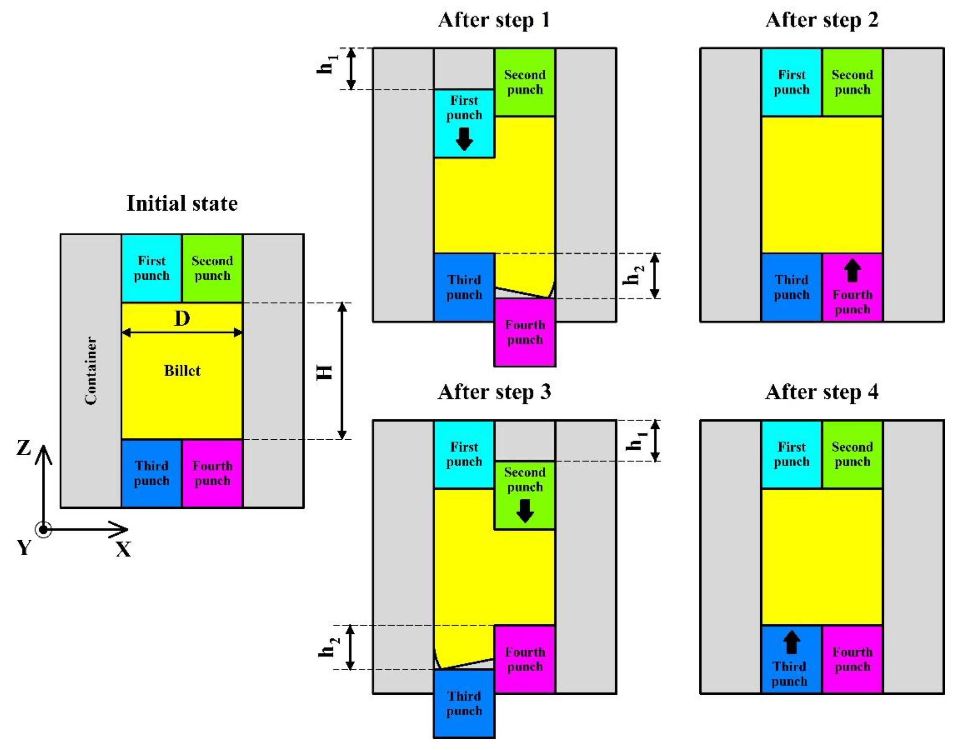
Figure 2.
Monitored points in XZ plane of the billet in the initial state for the FEA of the stress and strain distribution.
Figure 2.
Monitored points in XZ plane of the billet in the initial state for the FEA of the stress and strain distribution.
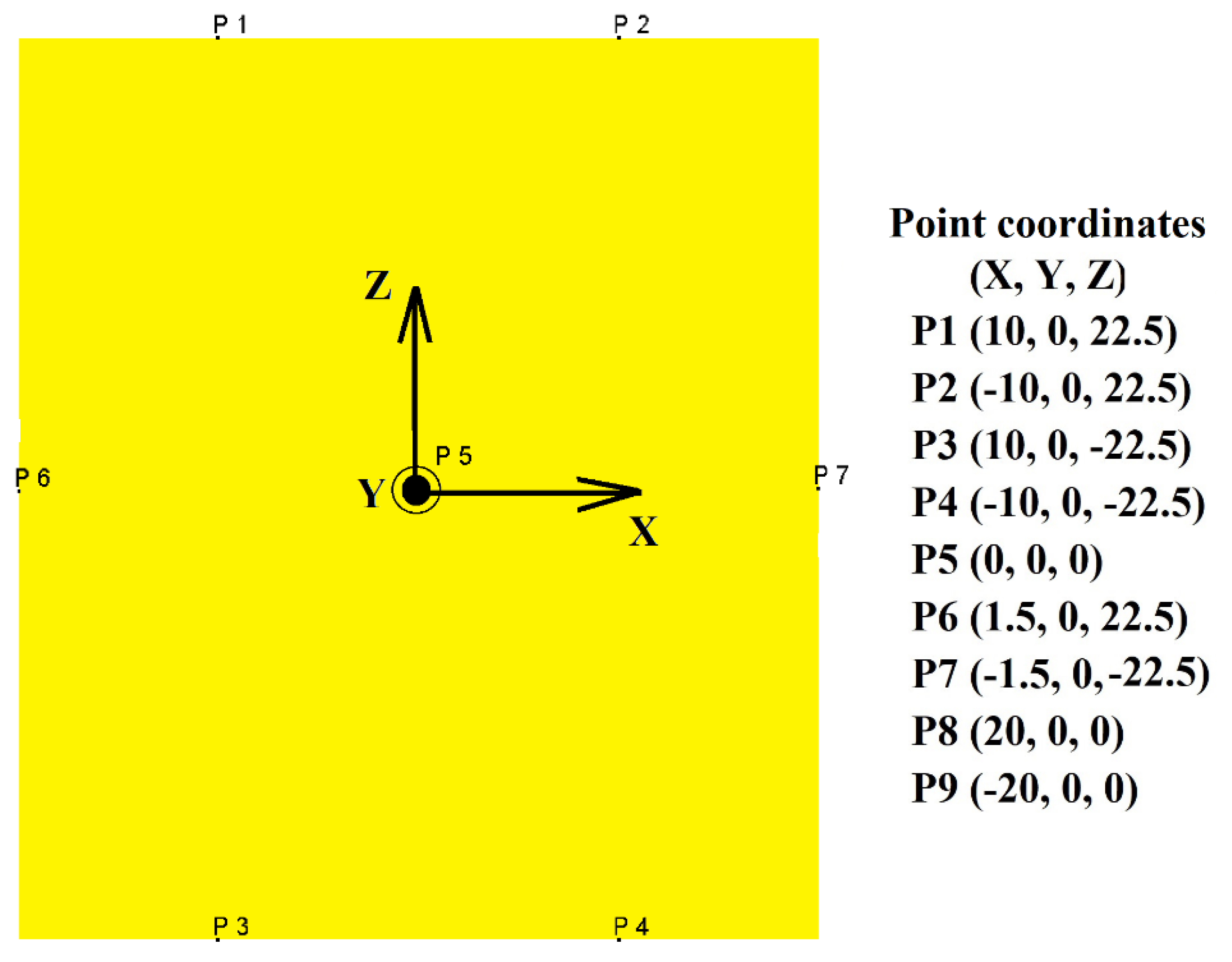
Figure 3.
Metal flow behavior in the ACF after (a) step 1, (b) step 2, (c) step 3, and (d) step 4. Red circles mark the generated vortex flows.
Figure 3.
Metal flow behavior in the ACF after (a) step 1, (b) step 2, (c) step 3, and (d) step 4. Red circles mark the generated vortex flows.
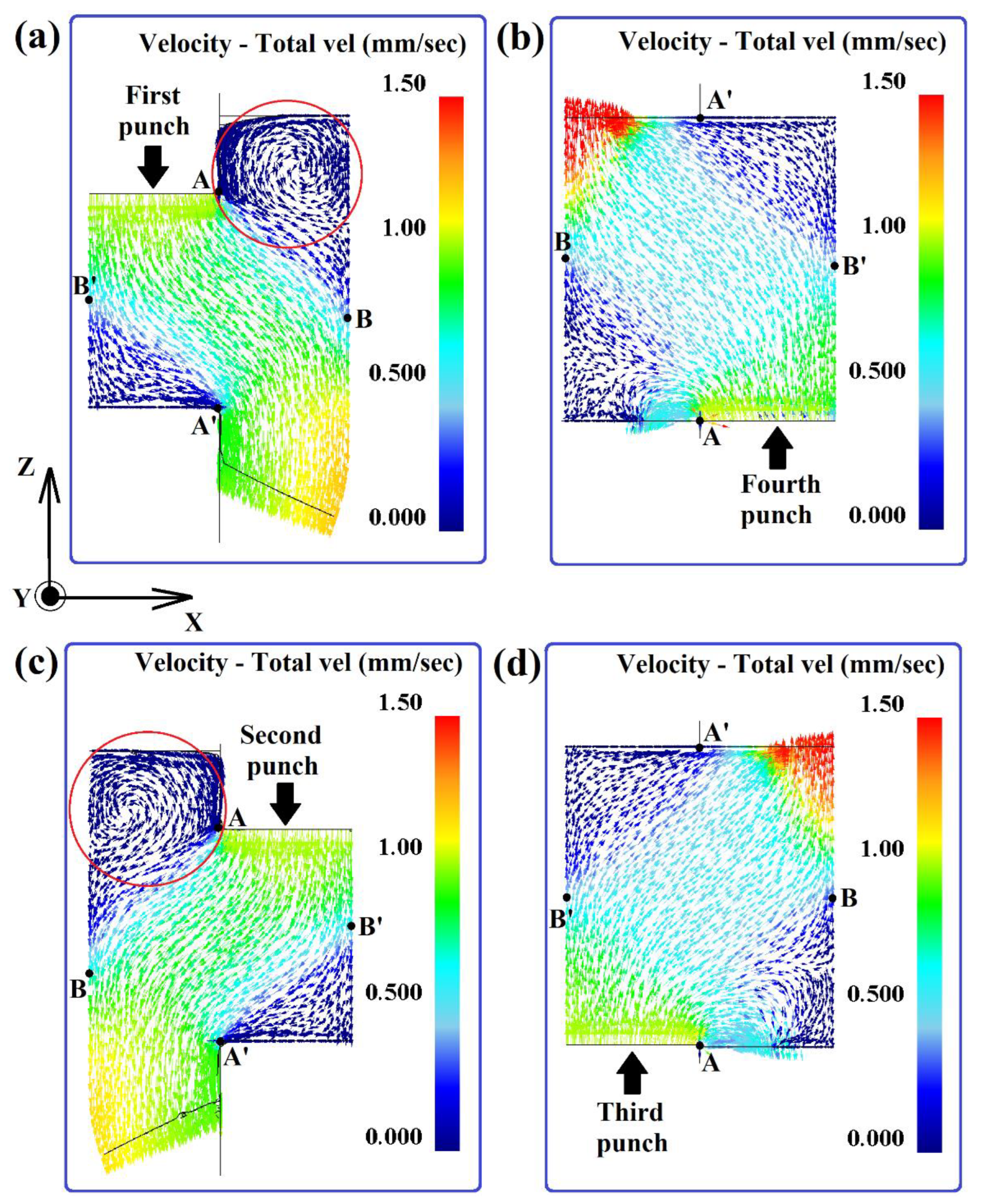
Figure 4.
Effective strain distribution in the ACF after each step: (a) after step 1, (b) after step 2, (c) after step 3, and (d) after step 4.
Figure 4.
Effective strain distribution in the ACF after each step: (a) after step 1, (b) after step 2, (c) after step 3, and (d) after step 4.
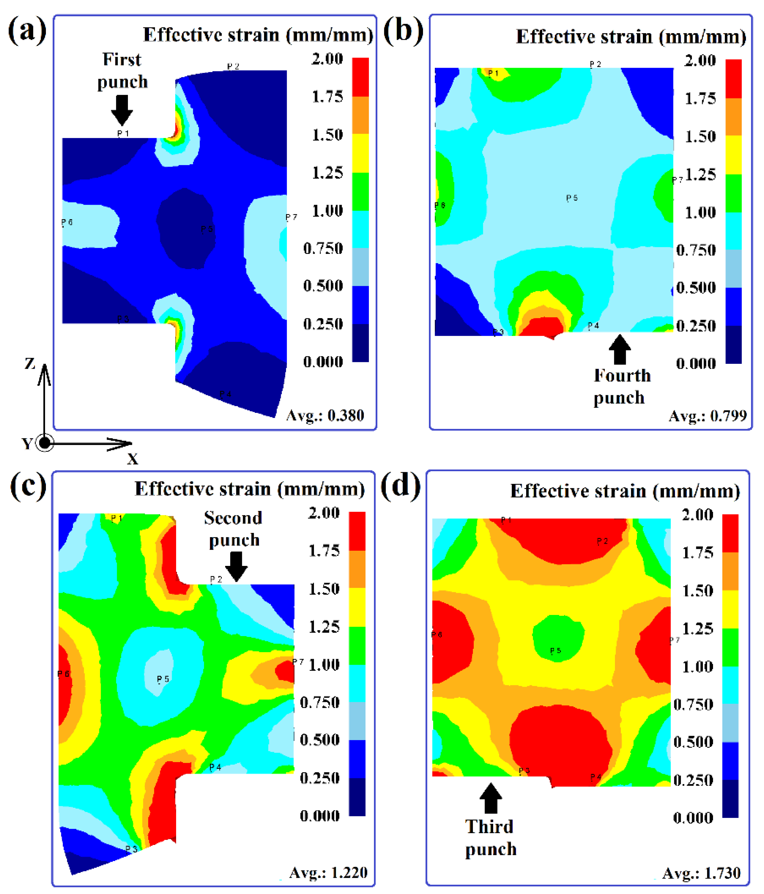
Figure 5.
The proportions of effective strain in the ACF by strain value (%).
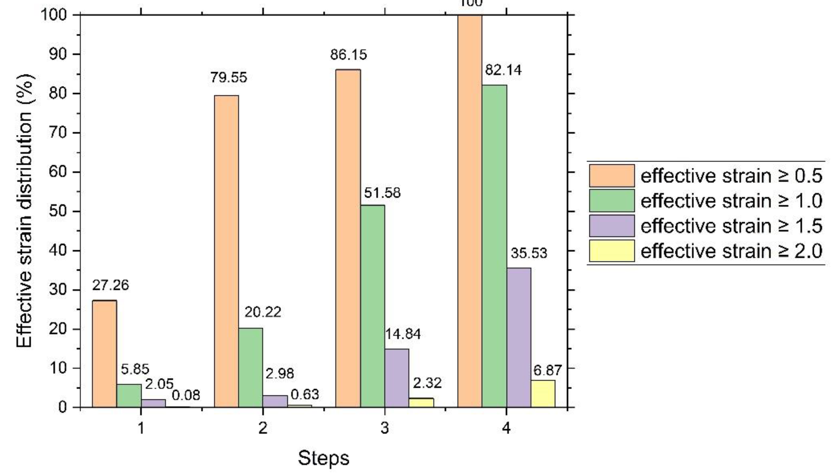
Figure 6.
Changes in effective strains across the tracked points: (a) absolute values and (b) average values over four steps (passes) of the deformation cycle.
Figure 6.
Changes in effective strains across the tracked points: (a) absolute values and (b) average values over four steps (passes) of the deformation cycle.
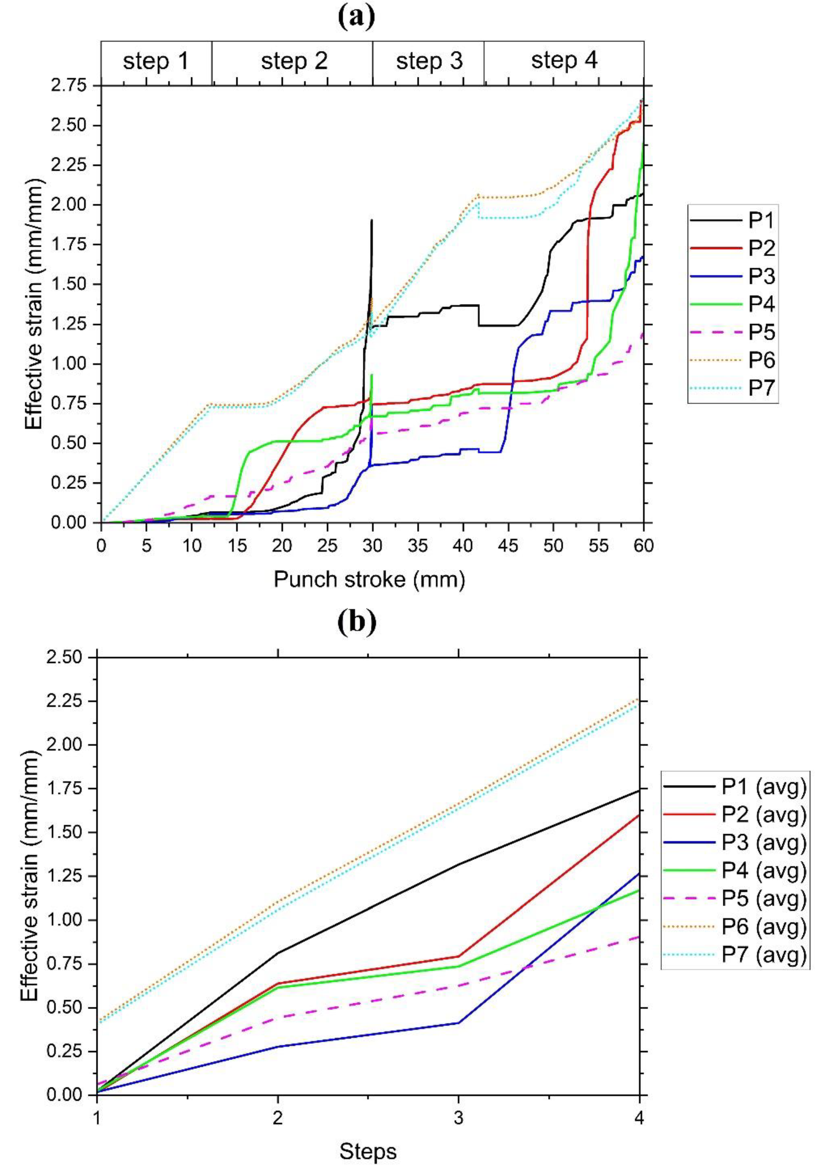
Figure 7.
Effective stress distribution in the ACF: (a) after step 1, (b) after step 2, (c) after step 3, and (d) after step 4.
Figure 7.
Effective stress distribution in the ACF: (a) after step 1, (b) after step 2, (c) after step 3, and (d) after step 4.
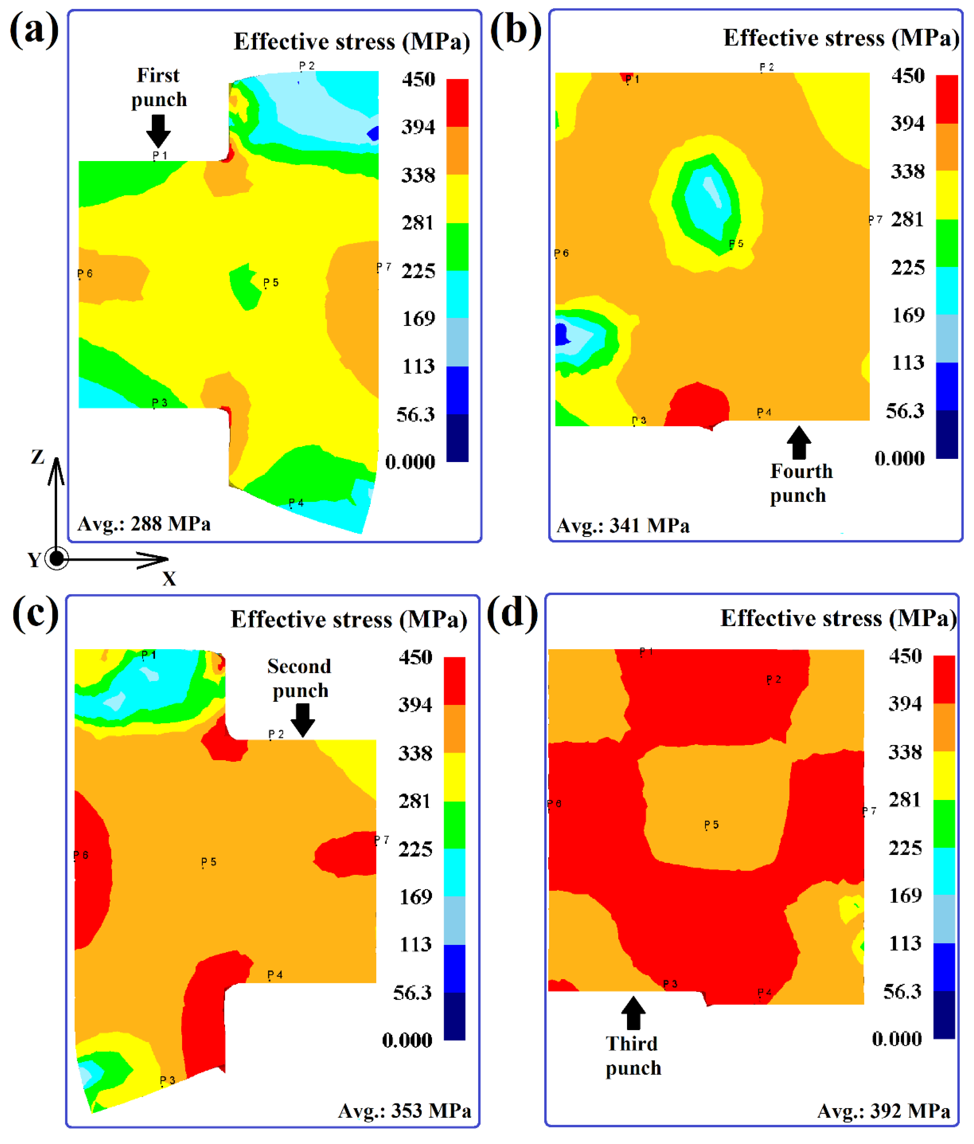
Figure 8.
The proportions of effective stresses in the ACF by the stress value (%).
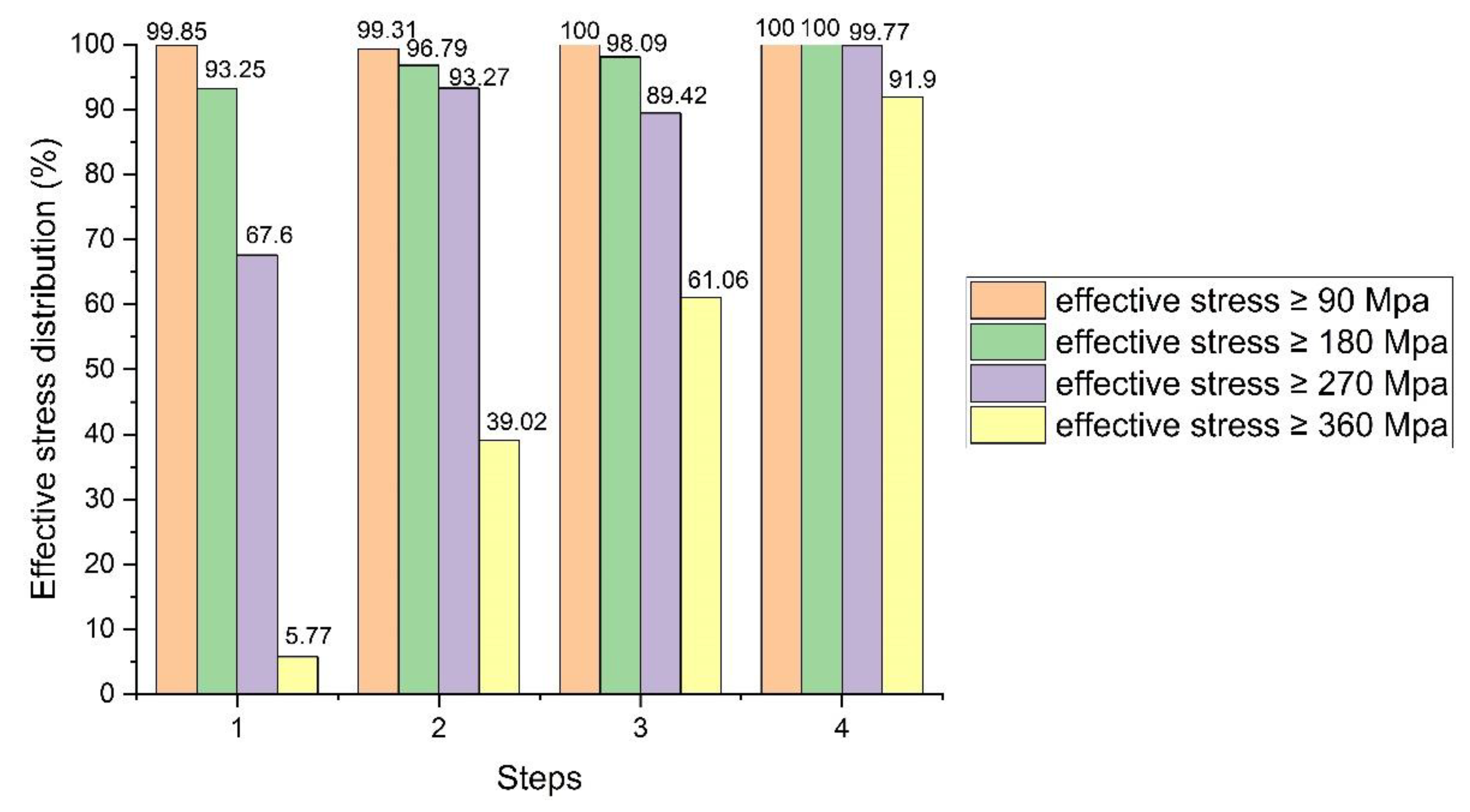
Figure 9.
Changes in absolute values of effective stresses by points.
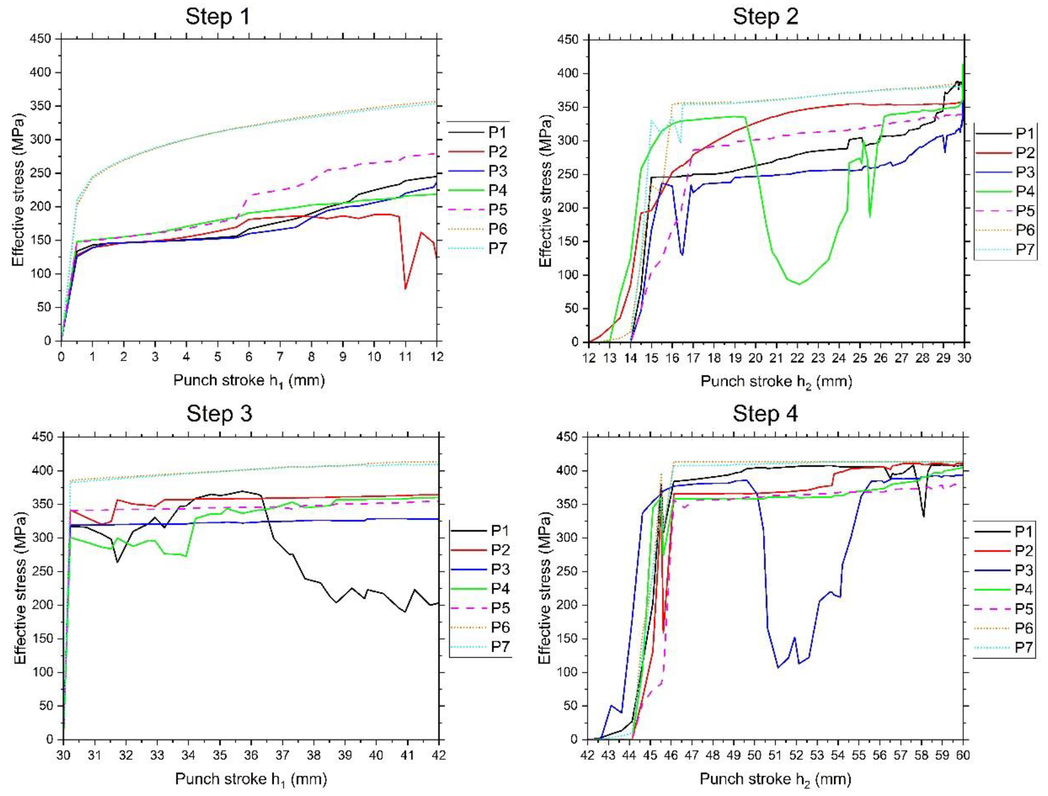
Figure 10.
Change in average values of effective stresses by points.

Figure 11.
Load-stroke curves in the ACF.
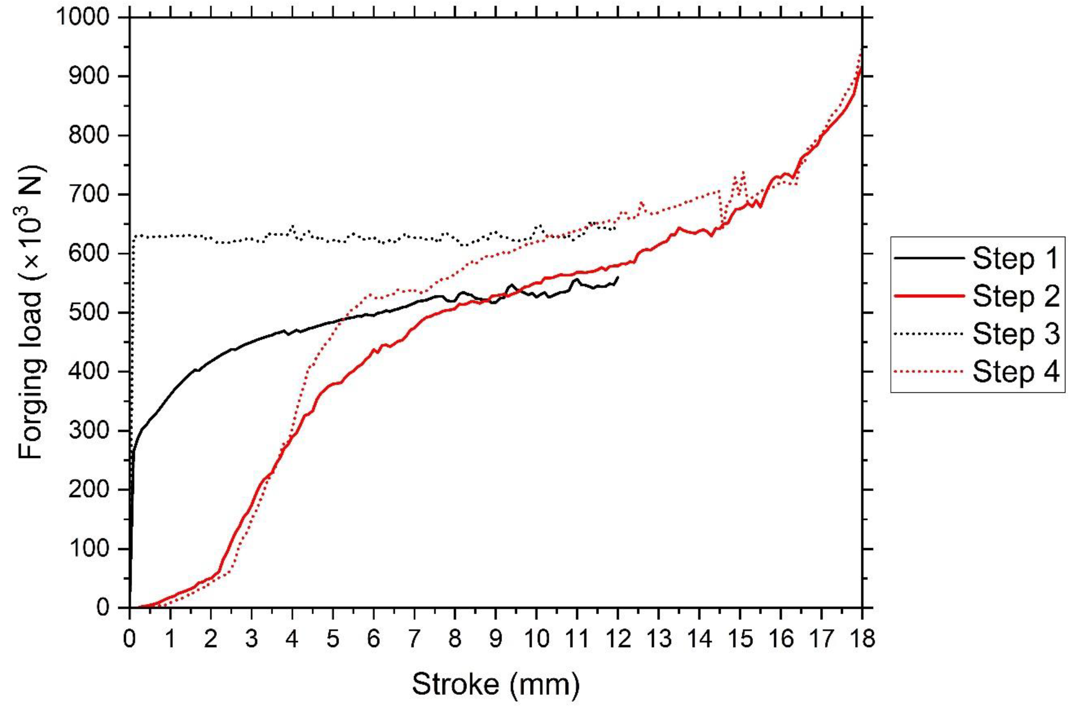

Table 1.
Main parameters of FEA.
| Billet diameter (D) | 40 mm |
|---|---|
| Billet height (H) | 45 mm |
| Billetmaterial (type) | Al 6061-Т4 (plasticity material) |
| Tooling material type | Rigid |
| Billet temperature (T) | 20 °C (cold forging) |
| Number of elements for billet | 34,767 tetrahedron elements (6,971 nodes) |
| Forging speed (v) | 1 mm/s (for all four punches) |
| Coefficient of friction (μ) | 0.12 (shear friction factor) |
| Punch stroke (h1) Punch stroke (h2) |
12 mm (first and second punches) ~18mm (third and fourth punches) |
| Simulation type | Lagrangian incremental |
| Iteration | Direct method |
| Solver | Conjugate gradient method |
| Remeshing | Global |
| Relative interference depth | 0.7 |
Disclaimer/Publisher’s Note: The statements, opinions and data contained in all publications are solely those of the individual author(s) and contributor(s) and not of MDPI and/or the editor(s). MDPI and/or the editor(s) disclaim responsibility for any injury to people or property resulting from any ideas, methods, instructions or products referred to in the content. |
© 2024 by the authors. Licensee MDPI, Basel, Switzerland. This article is an open access article distributed under the terms and conditions of the Creative Commons Attribution (CC BY) license (http://creativecommons.org/licenses/by/4.0/).
Copyright: This open access article is published under a Creative Commons CC BY 4.0 license, which permit the free download, distribution, and reuse, provided that the author and preprint are cited in any reuse.


