

Submitted:
23 July 2024
Posted:
24 July 2024
You are already at the latest version
Abstract
In the future, the power of commercial ocean current generators can reach MW level, and the corresponding mooring rope tension is very great. But the power of the ocean current generator in research stage is KW level and it can bear less rope tension. Its main mooring rope adopts a single cable and a single foundation. This paper studies the dynamic response and rope tension of the MW-level ocean current generator mooring system. It is assumed that the commercial MW-level ocean current generator is similar to the research-type KW level, and the similarity law and several dimensionless similar parameters are proposed, including for the turbine and platform the power number, tip speed ratio, hydrodynamic damping and stiffness coefficient and others. Based on these dimensionless similar formula and the known parameters of the researched KW-level convertor, all parameters of the MW-level ocean current generator are derived. In order to overcome the extreme tension of a MW-level mooring system and provide good stability, this paper proposes the pulley-traction rope design to replace the traditional single traction rope design.
The static and dynamic mathematical models of this mooring system subjected to typhoon wave impact and current are proposed and analytical solutions are obtained. The study found that the dynamic rope tension of the MW-level system with the traditional single rope system is significantly greater than its fracture strength and the dynamic tension of the pulley- traction rope system. It means that this design can effectively reduce the dynamic rope tensions of the mooring system. Moreover, if the length ratio of rope A to the seabed depth is within a safe range, the maximum rope dynamic tension will be less than the fracture strength.
In addition to the MW level, the dynamic response of the 700kW level power generation system under the action of typhoon waves is also studied. It is discovered that the dynamic tension of rope D is the largest. In addition, the dynamic tension of rope D for 700kW system will exceed the original strength of design. However, only the specification of rope D is increased, the new dynamic tension is still close to the original such that the dynamic tension of rope D is significantly less than the adjusted fracture strength and the mooring system becomes safety.
Keywords:
similarity law
; MW convertor
; stability
; dynamic tension
; ocean current
; hydrodynamic damping
; translational displacement
; rotational displacement
; pulley-traction rope design
; platform
; pontoon
; two foundations
1. Introduction
Global ocean currents are rich in energy. The potential electricity capacity in the Taiwan Kuroshio current is over 4GW [1]. The core technologies of ocean current power generation are being investigated [1,2,3,4,5]. The relevant technologies include (1) the high-efficiency convertor, (2) the deep mooring technology for over 1000m depth seabed beneath the current, (3) the protection from the typhoon wave impact, (4) double main traction ropes for high power convertor, and (5) the investigation of the mathematical model with the fluid-structure interaction (FSI).
WanChi company developed a 50 kW ocean current convertor which the blade is pushed by the current force and moved in the translational motion. Chen et al. [1] successfully tested the 50 kW WanChi convertor moored to the 850 m deep seabed beneath Kuroshio current at Taiwan Pingtung sea area. IHI and NEDO [2] developed a 100 kW ocean current convertor which was integrated by two sets of rotational turbines. The 100kW convertor was successfully tested by mooring to the 100 m deep seabed beneath the Japan Kuroshio current. Guo et al. [3] developed a 20 kW ocean current convertor which was integrated by two sets of rotational turbines. The 20kW convertor was tested by mooring it to the 80 m deep seabed beneath the Taiwan Liuqiu sea area.
The deep mooring theory and technology for the ocean current convertor system are important. A few of literatures investigated the dynamic stability of this mooring system under the coupled current-wave effect. WanChi company further developed a 400 kW ocean current convertor following the principle of the 50 kW ones. Lin et al. [4] proposed the mathematical model of the 400 kW ocean convertor-pontoon-traction rope-foundation mooring system under the coupled regular wave-ocean current effects. The motion of this system is four degrees of freedom. The dynamic system include the heaving motion of pontoon and the coupled surging-heaving-pitching motion of the convertor. The dynamic performance and stability of the system under coupled wave-current effect were investigated. Lin and Chen [5] proposed a towed parachute-platform-traction rope-foundation mooring system which protected the submarined platform from the typhoon wave impact. The concentrated mass model was considered. The motion of this system was three degrees of freedom. The coupled motions included surging and heaving of elements. It was theoretically verified the protection function of the proposed methodology under Typhoon wave impact. Lin et al. [6] presented the submarined ocean convertor-surfaced platform-pontoon-traction rope-foundation mooring system. The concentrated mass model was considered. The motion of this system was five degrees of freedom. The coupled motion included surging and heaving of elements. The dynamic stability of the mooring system under the regular wave and steady ocean current was investigated. Lin et al. [7] presented the submarined ocean convertor-submarined platform-2 pontoon-traction rop-foundation mooring system. The concentrated mass model was considered. The motion of this system was six degrees of freedom. The coupled motion included surging and heaving of elements. The dynamic response of this mooring system under the typhoon irregular wave of at Taiwan’s Green Island during the 50-year regression period was investigated. Lin et al. [8] designed a 400kW convertor composed of two rotating horizontal turbines. The hydrodynamic damping and stiffness coefficients were determined by using the computational fluid method. The submarined 400kW convertor-submarined platform-2 pontoon-traction rop-foundation mooring system was considered. The motion of this system was eighteen degrees of freedom. The coupled 3D motion included the translational and rotational of elements. The frequency spectrum of the system with the coupled fluid-structure interaction and regular wave was studied. Further, Lin et al. [9] investigated the transient performance of the 18 DOF mooring system with inital conditions. Pierson and Moskowitz [10] proposed the Jonswap spectrum and confirmed it with experimental measurement results. To simplify actual irregular ocean waves, a limited number of regular wave are usually used to approximate the irregular wave [7]. This study will take several regular waves to simulate irregular waves according to the experimental significant wave height, frequency and the Jonswap wave spectrum. In the literatures [4,5,6,7,8,9], the mooring traction rope is single only. However, for high power convertor its traction force is very great, two traction ropes is necessary. The relavant investgation is helpful for the ocean energy technology.
Theorem and technology of fluid structure interaction (FSI) are widely applied in many different fields including marine engineering [11,12], aerodynamics [13], acoustics [14] and biomechanics [15]. Due to the complexity of the fluid-structure interaction, a few literatures investigated the FSI problem by using analytical method [15], but mostly the numerical methods: (1) the boundary element method [13], (2) the finite-volume method [16], (3) the Coupled SPH–FEM [17].
So far, the relative literatures proposed one single main mooring rope connecting to one foundation. For the high-power ocean current convertor, this study designs a pulley-traction rope set which the rope connects to the two foundations. The similarity law is proposed to calculate the hydrodynamic damping and stiffness coefficient of turbine and platform. The static and dynamic equations of this ocean current power generation anchoring system are proposed to study the rope tension and stability under irregular waves.
2. Mathematical Model
To avoid the wave impact of typhoons, the energy convertor and the floating platform were submerged to a safe depth. For safely mooring a high power ocean convertor this study presents a pulley- traction rope set composed of a pulley and one main rope connected to two separate foundations, as shown in Figure 1. The coupled translational-rotational motion of the mooring system under coupled wave-current effect are considered. The motion is eighteen degrees of freedom. The governing equations of this mooring system are derived as follows:
The global translational and the rotational displacements of the components are.
The total tensions of the ropes are
These displacements and tensions include (1) the static one under the steady current only, (2) the dynamic one due to the wave impact and current. Because rope A connects to the pulley fixed to the platform and two foundations, the tension of rope A1 is equal to that of rope A2, , and .
3. Static Displacements and Equilibrium under the Steady Current only
3.1. Static Displacements
Under the steady current only, the static displacements of the components are
Foundation:
,
Platform:
The lengths of rope A1 and A2 are
The static displacements and parameters of mooring system, andchange with the current direction. These parameters can be determined by using the static equilibrium principle later.
Turbine:
Pontoons 3, 4:
Rotational angles of platform and convertor:
The global setting angle qBs of rope B is
The relation between the x-y-z and x′-y′-z′ coordinates is
where
3.2. Static Force Equilibrium
Under the steady current only, the static equilibrium of the energy convertor in the current direction is
where the drag of the convertor under steady current . The static equilibrium of the platform in the current direction is
where the drag of the platform under steady current, and. Because the rope A connects to the pulley, as shown in Figure 2, the tensions of ropes A1 and A2 are
Based on Equations (20-22), the static tension of rope A is expressed as
The static equilibrium of the platform in the x-direction is
The static equilibrium of the platform in the z-direction is
The static equilibrium of the energy convertor in the x-direction is
The static equilibrium of the pontoon 3 in the x-direction is
The static equilibrium of the pontoon 4 in the x-direction is
3.3. Solution Method of Static Equilibrium and Displacements
Substituting Equations (7-9) into Equation (25), one obtains
where , ,
, ,
.
If the basic parametersare given, the length of rope A1, LA1, can be determined by using the bisection method via Equation (29). Substituting LA1 back into Equations (8-9,12-17), the parameters are obtained.
3.4. Static Numerical Results
Parameters of the mooring system are listed in Table 1.
Figure 3 demonstrates that the convertor direction is almost same as current. The distance LF between two foundations increases slightly the deviation of the convertor direction from current.
Figure 4 shows the effects of the current direction and the distance LF between two foundations on the static tension of rope A, TAs. If the current velocity Vcur=1.5m/s, the drag of the convertor FDT=59.35tons and the drag of the platform FDB=0.077tons. If the traditional single traction rope is considered, the corresponding rope length is 2480m and the tension TAs =68.62tons. However, if LF =0.1LA in this proposed system, the tension TAs is about 34tons only. It is half of the traditional traction rope. The current direction decreases the static tension TAs. Moreover, the larger the distance LF is, the larger the static tension TAs is.
4. Dynamic Analysis
4.1. Similarity of System
4.1.1. Hydrodynamic Similarity of Convertor
Lin et al. [8] presented the hydrodynamic coefficients of fluid-structure interaction of a 400kW turbine and platform determined by using computational fluid dynamics method. An ocean current convertor of MW level is commercial specification. In this study, the dynamic response of a 1 MW turbine mooring system will be investigated. The corresponding hydrodynamic coefficients and other parameters are determined based on the similarity law and the presented parameters [8]. The similarity law is presented as follows:
Similarity of tip speed ratio (TSR):
Lin et al. [8] proposed that TSR=3.5 for the 400kW turbine, the efficiency is maximum. Considering the same current velocity Vcur for the model and prototype, Equation (31) becomes
Similarity of power number Np:
Considering the same current velocity Vcur and sea density r for the model and prototype and substituting Equation (31) into Equation (32),
Similarity of hydrodynamic force and moment for convertor:
The hydrodynamic force of convertor is
Dividing Equation(34) by , it becomes one in terms of dimensionless variables
where
If the prototype and the model are similar, their dimensionless force coefficients (35) are same
Based on Equations (35-37), one can obtain the following similar parameters
Similarity of drag force coefficient is
Similarity of hydrodynamic damping force coefficient:
Similarity of hydrodynamic stiffness force coefficient:
Based on the similar formula (36, 39, 40), the hydrodynamic damping force relations between the model and prototype
and the hydrodynamic stiffness force relation
Given the coefficients of the model and substituting Equations (31, 33) into Equations (41-43), the hydrodynamic damping and stiffness force coefficients of the prototype can be obtained.
According to the similarity of drag force coefficient (38), the drag force relation is
Based on Equation (44), the similarity of fracture strength of rope is
The hydrodynamic moment of convertor is
Dividing Equation (46) by , it becomes one in terms of dimensionless variables
where .
If the prototype and the model are similar, the two dimensionless moments (47) are same
Based on Equations (47-48), one can obtain the following similar parameters
Similarity of drag moment coefficient is
Similarity of hydrodynamic damping in moment:
Similarity of hydrodynamic stiffness in moment:
Based on the similar formula (36, 50-51), the hydrodynamic damping moment relations between the model and prototype
and the hydrodynamic stiffness moment relation
Given the coefficients of the model and substituting Equations (31, 33) into Equations (52-54), the hydrodynamic damping and stiffness moment coefficients of the prototype can be obtained.
4.1.2. Hydrodynamic Similarity of Platform
The hydrodynamic force of platform is
Dividing Equation(55) by , it becomes in terms of dimensionless variables
where
If the prototype and the model are similar, the two dimensionless force coefficients (56) are same
Based on Equations (56-58), one can obtain the following similar parameters.
Similarity of hydrodynamic damping force coefficient:
Similarity of hydrodynamic stiffness force coefficient:
Based on Equations (57, 59-60), the hydrodynamic damping force relations between the model and prototype
and the hydrodynamic stiffness force relation
Given the coefficients of the model and substituting Equations (31, 33) into Equations (61-63), the hydrodynamic damping and stiffness force coefficients of the prototype can be obtained.
The hydrodynamic moment of platform is
Dividing Equation(64) by , it becomes one in terms of dimensionless variables
where .
If the prototype and the model are similar, their dimensionless moments (65) are same
Based on Equations (63-64), one can obtain the following similar parameters.
Similarity of drag moment coefficient is
Similarity of hydrodynamic damping in moment:
Similarity of hydrodynamic stiffness in moment:
Based on the similar formula (36, 68-69), the hydrodynamic damping moment relations between the model and prototype
and the hydrodynamic stiffness moment relation
Given the coefficients of the model and substituting Equations (31, 33) into Equations (70-72), the hydrodynamic damping and stiffness moment coefficients of the prototype can be obtained.
4.1.3. Geometrical Inertia and Buoyance Similarities
Based on the similarity formula (33) and considering the geometry similarity, one can obtain the similar relations
Similarity of mass:
Similarity of inertia of mass:
Similarity of buoyance:
4.2. Translational Motion in the x-Axis Direction
4.2.1. Equation of Heaving Motion for Pontoon 3
The heaving equation of the pontoon 3 is
where is the irregular wave force applied to Pontoon 3, and.
The effective spring constant of the rope C- buffer spring connection
where is the constant of the spring connecting with the rope C. in whichand LC are the Young’s modulus, cross-sectional area and length of the rope C, respectively.
The dynamic tension of the rope C,
where the dynamic elongation between the floating platform 1 and the pontoon 3, .
4.2.2. Equation of Heaving Motion for Pontoon 4
The heaving equation of the pontoon 4 is
where is the irregular wave force applied to Pontoon 4. and. The phase angle and . α is the relative wave-current angle, is the wave length, as shown in Figure 5.
The effective spring constant of the rope D- buffer spring connection
in which is the constant of the spring connecting with the rope D. where and LD are the Young’s modulus, cross-sectional area and length of the rope D, respectively.
The dynamic tension of the rope C
where the dynamic elongation between the invertor 2 and the pontoon 4, .
4.2.3. Equation of Heaving Motion of the Platform
The dynamic equilibrium of the floating platform in the heaving motion is
where the effective mass meff,x is derived in Appendix A. The hydrodynamic force on the floating platform due to the fluid-structure interaction (FSI) is expressed in Taylor series as follows:
For the briefly, k = 1, 2. When the symmetry configuration of the platform is considered, the hydrodynamic force on the platform in the x-direction under the current only=0. Considering small oscillation, the higher order terms are neglected later. The right-handed side second term of Equation (84) is the hydrodynamic force due to the fluid-structure interaction.
The dynamic tensions of the ropes A and B are
The dynamic elongation is the difference between the dynamic and static lengths, , β=A, B. Using the Taylor formula, the dynamic elongation of rope A is derived,
where
, ,
The dynamic elongation of rope B
where .
Substituting Equations (84-87) into Equation (83), one obtains
4.2.4. Equation of Heaving Motion for the Convertor
The dynamic equilibrium of the convertor in the heaving motion is [8]
4.3. Translational motion in the y-direction
4.3.1. Equation of Surging Motion of Platform
The dynamic equilibrium of the floating platform in the surging motion is
where the effective mass meff,y is derived in Appendix A. The hydrodynamic force
where
Substituting Equations (23, 85-87, 91) into Equation (90), one obtains
where
4.3.2. Equation of Surging Motion of Convertor in the y-direction
The dynamic equilibrium of the convertor in the surging motion is
The hydrodynamic force on the convertor is expressed as
where , ATy is the effective operating area of the convertor..
Substituting Equations (85, 87, 94) into Equation (93), one obtains
4.3.3. Equation of Surging Motion of Pontoon 3 in the y-direction
The dynamic equilibrium of the pontoon 3 in the surging motion is
4.3.4. Equation of Surging Motion of Pontoon 4 in the y-direction
The dynamic equilibrium of the pontoon 4 in the surging motion is
4.4. Translational motion in the z-direction
4.4.1. Equation of Swaying Motion of Platform
The dynamic equilibrium of the floating platform in the swaying motion is
where the effective mass meff,z is derived in Appendix A. The hydrodynamic force
Considering small displacements and based on Equations (79, 85-87, 99), one obtains
4.4.2. Equation of Swaying Motion of Convertor
The dynamic equilibrium of the convertor in the swaying motion is
4.4.3. Equation of Swaying Motion for Pontoon 3
The dynamic equilibrium of the pontoon 3 in the swaying motion is [8]
4.4.4. Equation of Swaying Motion of Pontoon 4
The dynamic equilibrium of the pontoon 4 in the swaying motion is [8]
4.5. Rotational motion
4.5.1. Equation of Yawing Motion of Convertor
The dynamic equilibrium of the convertor in the yawing motion is [8]
4.5.2. Equation of Rolling Motion of Convertor
The dynamic equilibrium of the convertor in the rolling motion is [8]
4.5.3. Equation of Pitching Motion of Convertor
The dynamic equilibrium of the convertor in the pitching motion is [8]
4.5.4. Equation of Yawing Motion of Platform
The dynamic equilibrium of the floating platform in the yawing motion is
where . Substituting Equations (85-87) and hydrodynamic moment mpx into Equation (107), one obtains
4.5.5. Equation of Rolling Motion of Platform
The dynamic equilibrium of the floating platform in the rolling motion is
where . Substituting Equations (79, 85-86) and hydrodynamic moment mpy into Equation (109), one obtains
4.5.6. Equation of Pitching Motion of Platform
The dynamic pitching equilibrium of the floating platform about the z-axis is
where . Substituting Equations (79, 85-86) and hydrodynamic moment mpy into Equation (111), one obtains
4.6. Solution Method of Dynamic Displacements
The governing equations (77, 80, 88-89, 92-97, 100-106, 108, 110, 112) can be expressed in matrix format
where the dynamic displacement vector.
The elements of the force vector
where
According to the FSI parameters of 400kW convertor and platform presented by Lin et al. [8] and considering the similarity of some prototype of different power, for example, 1 MW. The elements of the mass matrix , the damping matrix and the stiffness matrix for the prototype of MW-level are determined by using the similar formula in section 4-1 and listed in Appendix B, C and D, respectively. Equation (113) can be rewritten as
where
The solution can be expressed as
where
Substituting the solution (118) into Equation (116), one obtains
By using the balanced method for Equation (120), one obtains
where
.
and
where , , and .
Equations (121-122) can be expressed as
where
The solution of Equation (123) is
4.8. Dynamic Tensions of Ropes
Under irregular wave, the dynamic tension of rope A is
where . The dynamic tension of rope B is
Where
The dynamic tension of rope C is
where . The dynamic tension of rope D is
where .
5. Dynamic Response and Discussion
Referring the information from the Central Meteorological Bureau Library of Taiwan about the typhoon invading Taiwan from 1897 to 2019 [18] and selecting 150 typhoons greatly affecting Taiwan’s Green Island, the significant wave height Hs during the 50-year regression period Hs =15.4m, the peak period Tw = 16.5sec. Letting N=6, the irregular wave is simulated by six regular waves listed in Table 2 [19]. Figure 6 demonstrates the relation between the significant height Hs and the amplitudes of six regular simulating waves. Table 2 shows that the second wave frequency is completely consistent with the significant frequency. Figure 5 demonstrates that the amplitude of the second wave is significantly larger than that of other waves. The larger the significant wave height Hs is, greatly the larger the amplitudes of the six regular waves are.
The dynamic response of an ocean current convertor of 1 MW power under Typhon irregular wave and current direction is investigated, as shown in Figure 7. The corresponding hydrodynamic coefficients and other parameters are determined based on the similarity law derived in Section 4.1 and listed in Appendix C, D. The parameters of the mooring system are listed in Table 3
Figure 7 demonstrates the effects of the distance of two foundations LF and the current directionon the maximum rope tensions and the displacements of elements under typhon irregular wave. As shown in Figure 7(a), the effect of the current direction on the maximum dynamic tensions of ropes is great. The maximum dynamic tension of rope D, TD,max, is significantly larger than the others. The larger the distance of two foundations is, the larger the maximum dynamic tensions are. As shown in Figure 7(b), the maximum heaving displacements of all the elements are greatest. The surging displacement are next. The swaying displacements are negligible. The effect of the current direction on displacements is negligible. As shown in Figure 7(c), the pitching angle of the platformis about 2o. The other angular displacement of platform and turbine are very small.
on the maximum rope tensions and the displacements of elements.
Figure 8 demonstrates the comparison of dynamic rope tensions of the traditional mooring system with a single rope A and one with a pulley-rope set under typhoon irregular wave. All the parameters are listed in Table 3. The distance of two foundations LF=0.2LA. Figure 8 shows that the dynamic rope tensions of the traditional mooring system with a single rope A are significantly greater than those of the presented one with a pulley- rope set. The dynamic rope tensions TAd,max and TBd,max of the traditional system are larger than the fracture strength Tfrac=2000tons. However, all the dynamic tensions of the pulley- traction rope system is smaller than the fracture strength Tfrac=2000tons. Obviously, the pulley-rope design can effectively reduce the dynamic rope tensions. For the traditional system, the dynamic tension of rope B is the greatest. However, for the pulley-rope system, the dynamic tension of rope D is the greatest. The dynamic tension of the rope in the traditional system has nothing to do with the current direction fcur, while the dynamic rope tensions of the pulley-rope system is significantly related to the current direction fcur.
Figure 9 demonstrates the effects of the rope length ratio rAH = LA /Hbed and the current directionon the dynamic rope tensions of the pulley-rope system of 1 MW under typhoon irregular wave. The distance between two foundations LF=0.2LA. Other parameters are the same as those of Table 3. As shown in Figure 9(a), if Hbed =1300m, , the maximum dynamic tensions TDd,max is smaller than the fracture strength Tfrac=2000tons. If Hbed =1300m, , the maximum dynamic tensions TDd,max is smaller than the fracture strength Tfrac=2000tons. As shown in Figure 9(b), if Hbed =1000m, , the maximum dynamic tensions TDd,max is smaller than the fracture strength Tfrac=2000tons. If Hbed =1000m, , the maximum dynamic tensions TDd,max is smaller than the fracture strength Tfrac=2000tons. It is concluded that for a convertor of 1 MW power and Hbed =1300m, the rope length ratio, , all the dynamic tensions can be smaller than the fracture strength. If Hbed =1000m, the rope length ratio, , all the dynamic tensions can be smaller than the fracture strength.
Figure 10a demonstrates the effects of the buffer spring constant gKB and the current directionon the dynamic rope tensions of the pulley-rope system of 1 MW under typhoon irregular wave. The buffer springs A, C, and D are not installed. The distance between two foundations LF=0.2LA. Other parameters are the same as those of Table 3. It is found that if the buffer spring constant gKB<30, the maximum dynamic tensions are greater than the fracture strength of rope Tfrac=2000tons.
When the buffer spring constant gKB>100, i.e., the buffer spring B is not installed, the maximum dynamic tension TDd,max ()=1259 tons, TDd,max ()=839 tons are both less than the fracture strength 2000tons. Figure 10b demonstrates the effects of the buffer spring constant gKD and the current directionon the dynamic rope tensions of the pulley-rope system of 1 MW under typhoon irregular wave. The buffer springs A, B, and C are not installed. The distance between two foundations LF=0.2LA. Other parameters are the same as those of Table 3. It is found that if the buffer spring constant gKD<4.6, the maximum dynamic tensions are greater than the fracture strength of rope Tfrac=2000tons. When the buffer spring constant gKD>100, i.e., the buffer spring D is not installed, the maximum dynamic tension TDd,max ()=1259 tons, TDd,max ()=839 tons are both less than the fracture strength 2000tons. It is concluded that the pulley-rope system of 1 MW without the buffer springs A, B, C, and D under the typhoon irregular wave is safety.
The dynamic response of an ocean current convertor of 700 kW power under Typhon irregular wave and current direction is investigated, as shown in Figure 11. The corresponding hydrodynamic coefficients and other parameters are determined based on the similarity law derived in Section 4.1 and listed in Appendix C, D. The parameters of the mooring system are listed in Table 4.
Figure 11a demonstrates the effects of the buffer spring constant gKB and the current directionon the dynamic rope tensions of the pulley-rope system of 700 kW under typhoon irregular wave. The ropes A, B, C, and D have the same specification. The fracture strength Tj,frac=1400tons, j=A,B,C,D. It is found that if the buffer spring constant gKB≅10, the dynamic tension TDd,max is minimum and smaller than the fracture strength of rope Tfrac=1400tons. When the buffer spring constant gKD>100, i.e., the buffer spring D is not installed, the maximum dynamic tension TDd,max ()=1394 tons, TDd,max ()=1741 tons larger than the fracture strength 1400tons. To overcome this failure, only the specification of rope D is increased to TD,frac=2000tons as listed in Table 3. As shown in Figure 11b, when the buffer spring constant gKD>100, i.e., the buffer spring D is not installed, the maximum dynamic tension TDd,max ()=1392 tons, TDd,max ()=1738 tons smaller than the fracture strength 2000tons.
6. Conclusions
In this study, the similarity formulas of MW- and KW- level ocean convertor are constructed. According to these, the hydrodynamic damping and stiffness coefficients and other parameters of MW-level system can be determined. The novel pulley-main rope design for MW- level ocean convertor mooring system is proposed. Further, the mathematical dynamic model of a MW- level ocean convertor mooring system under irregular wave and current direction is derived. The analytical solution of this system is presented. The dynamic performance of the proposed 1 MW mooring system under irregular wave impact is investigated and discovered as follows:
1. The dynamic rope tensions TAd,max and TBd,max of the traditional single-traction rope system are larger than the fracture strength Tfrac=2000tons. However, all the dynamic tensions of the pulley-rope system are smaller than the fracture strength. Obviously, the pulley-rope design can effectively reduce the dynamic rope tensions.
2. The dynamic responses of the above two kinds of mooring systems are different. The traditional single traction rope system is not affected by the flow direction, but the pulley-rope system is.
3. The static tension of rope A of the proposed system under the steady current only is close to half of the traditional single traction rope system.
4. For Hbed =1300m, if the rope length ratio,
, all the dynamic tensions can be smaller than the fracture strength. For Hbed =1000m, if the rope length ratio, , all the dynamic tensions can be smaller than the fracture strength.
5. In a MW-level power generation system with the pulley-rope design, if buffer spring constant is very small, meanwhile the dynamic tension may become greater than the fracture strength. However, no buffer spring is set, it is reverse.
6. According to the theoretical analysis, the proposed MW-level ocean convertor mooring system with the pulley-rope design under typhoon wave impact is safety.
Acknowledgments
The support of GETRC from The Featured Areas Research Center Program within the framework of the Higher Education Sprout Project by MOE in Taiwan and the Ministry of Science and Technology of Taiwan, R. O. C. (NSTC 112-2218-E-110-008) are gratefully acknowledged.
Appendix A: Effective Masses of the Double Traction Sub-ropes
The effective masse
in the x-direction vibration:
As shown Figure 12, for the longitudinal vibration of the sub-ropes A1 and A2, the governing equation is
where is the dynamic displacement of the sub-rope A1 and A2.
The boundary conditions are
where u(t) is the dynamic x-direction displacement of platform. The relation between the displacement u and the elongation of the sub-ropes A1 and A2 is
The dynamic tension of the sub-ropes A1 and A2
Substituting Equations (A4-A5) into Equation (A3) and due to
,
The solution of Equation (A1) is assumed
Substituting Equation (A7) into Equation (A1), one obtains
The transformed boundary conditions are
The fundamental solution of Equation (A8) is assumed
Substituting Equation (A11) into Equation (A8),
The general solution of Equation (A8) is
Substituting (A13) into (A9),
. Substituting (A13) and (A14) into (A10), the frequency equation is obtained
where
. The dimensionless fundamental frequency
Via Equation (A14), one can determine the dimensionless frequency W.
The effective mass-spring model in the x-direction vibration is
where
. The frequency of Equation (A16) is
Substituting Equation (A16) into Equation (A17), the effective mass in the x-direction motion is
The effective masse
in the y-direction vibration:
In the similar way, the effective masse
in the y-direction vibration can be determined. The corresponding frequency equation is
where
. The dimensionless fundamental frequency W can be calculated via Equation (19). Further, the effective mass is
where
.
The effective masse
in the z-direction vibration:
In the similar way, the effective masse
in the y-direction vibration can be determined. The corresponding frequency equation is
where
. The dimensionless fundamental frequency W can be calculated via Equation (A21). Further, the effective mass is
where
.
Appendix B: Elements of the mass matrix
The translational inertia coefficients of platform 1:
;
;
;
The translational inertia coefficients of invertor 2:
;
;
;
The translational inertia coefficients of pontoon 3:
;
;
;
The translational inertia coefficients of pontoon 4:
;
;
The rotational inertia coefficients of invertor 2:
;
;
;
The rotational inertia coefficients of platform 1:
;
;
.
Appendix C: Elements of the Hydrodynamic Damping Matrix in similarity law
The translational hydrodynamic damping coefficients of platform 1:
The translational hydrodynamic damping coefficients of invertor 2:
,
The rotational hydrodynamic damping coefficients of convertor 2:
,
The rotational hydrodynamic damping coefficients of platform 1:
,
Other coefficients:
The above coefficients were presented by Lin et al. [8].
Appendix D: Elements of the Stiffness Matrix in similarity law
The translational stiffness coefficients of platform 1:
,
,
,
,
,
,
,
,
,
,
,
,
,
.
The translational stiffness coefficients of convertor 2:
,
,
The translational stiffness coefficients of pontoon 3:
;
;
The translational stiffness coefficients of pontoon 4:
;
The rotational stiffness coefficients of convertor 2:
,
,
,
;
,
,
;
The rotational stiffness coefficients of platform 1:
,
,
,
Nomenclature
| ai | amplitude of the ith regular wave |
| ABX: ABT | cross-sectional area of surfaced cylinder of pontoons 3 and 4, respectively |
| ABY, ATY | damping area of platform and convertor under current, respectively |
| damping coefficient of floating platform and convertor | |
| Ei | Young’s modulus of rope i, i = A, B, C, D |
| FB | buoyance |
| fp | significant frequency |
| fkj | hydrodynamic force of element k in the j-direction |
| , | the drag of the floating platform and the convertor under steady current |
| Hbed | depth of seabed |
| Hs | significant wave height |
| mass moment of inertia of the convertor and the platform about the j-axis. | |
| g | gravity |
| Kid | effective spring constant of rope i, |
| wave vector of the i-th regular wave | |
| Li | length of rope i |
| LE | horizontal distance between the convertor and platform, |
| Mi | mass of element i |
| effective mass of rope A in the i-direction | |
| hydrodynamic moment of convertor or platform about the i-axis | |
| coordinate | |
| distance between the center of gravity of invertor and the rope B, about the x-axis. | |
| distance between the center of gravity of invertor and the rope D, about the y-axis. | |
| distance between the center of gravity of invertor and the rope B, about the z-axis | |
| , | distances in the y-z plane from the center of gravity to the rope A and B, respectively |
| , | distances in the x-z plane from the center of gravity to the rope A and C, respectively |
| ,, | distances in the x-y plane from the center of gravity to the ropes A, B and C, respectively |
| Ti | tension force of rope i |
| t | time variable |
| V | ocean current velocity |
| Wi | weight of component i |
| wPE | weight per unit length of HMPE |
| xi, yi, zi | displacements of component i |
| xw | sea surface elevation |
| α | relative angle between the directions of wave and current |
| ρ | density of sea water |
| ωΤ | angular speed of turbine |
| Ω | angular frequency of wave |
| angular displacement of convertor or platform about the j-axis | |
| phase delay of wave, | |
| θi | angles of rope i |
| λ | length of wave |
| δi | elongation of rope i |
| Subscript: | |
| 0~4 | mooring foundation, floating platform, convertor, and two pontoons, respectively |
| A, B, C, D | Ropes A, B, C, and D, respectively |
| mod | model |
| iα, iβ | component α, β of rope i = A, B, C, and D |
| frac | fracture |
| s, d | static and dynamic, respectively |
| PE | PE dyneema rope |
| P | platform |
| pro | ptototype |
| T | convertor |
References
- Chen, Y. Y.; Hsu, H. C.; Bai, C. Y., Yang Y., Lee C. W., Cheng H. K., Shyue S. W., Li M. S. Evaluation of test platform in the open sea and mounting test of KW Kuroshio power-generating pilot facilities. In Proceedings of the 2016 Taiwan Wind Energy Conference, Keelung, Taiwan, 24–25 November 2016.
- IHI; NEDO. The demonstration experiment of the IHI ocean current turbine located off the coast of Kuchinoshima Island, Kagoshima Prefecture, Japan, 14 August 2017. Available online: https://tethys.pnnl.gov/project-sites/ihi-ocean-current-turbine (accessed on 28 August 2021).
- Guo et al. Manufacture and sea trial of 20 kW Floating Kuroshio Turbine. (2021) NAMR110050; Ocean Affairs Council: Kaohsiung, Taiwan, 2021. (In Chinese).
- Lin, S.M.; Chen, Y.Y.; Hsu, H.C.; Li, M.S. Dynamic Stability of an Ocean Current Turbine System. J. Mar. Sci. Eng. 2020, 8, 687. [Google Scholar] [CrossRef]
- Lin, S.M.; Chen, Y.Y. Dynamic stability and protection design of a submarined floater platform avoiding Typhoon wave impact. J. Mar. Sci. Eng. 2021, 9, 977. [Google Scholar] [CrossRef]
- Lin, S.M.; Chen, Y.Y.; Liauh, C.T. Dynamic stability of the coupled pontoon-ocean turbine-floater platform-rope system under harmonic wave excitation and steady ocean current. J. Mar. Sci. Eng. 2021, 9, 01425. [Google Scholar] [CrossRef]
- Lin, S.M.; Liauh, C.T.; Utama, D.W. Design and dynamic stability analysis of a submersible ocean current generator-platform mooring system under typhoon irregular wave. J. Mar. Sci. Eng. 2022, 10, 538. [Google Scholar] [CrossRef]
- Lin, S.M. , Utama D.W.; Liauh C.T. Coupled translational-rotational stability analysis of a submersible ocean current converter-platform mooring system under typhoon wave. J. Mar. Sci. Eng. 2023, 11, 518. [Google Scholar] [CrossRef]
- Lin, S.M. , Wang W.R.and Yuan H. Transient translational-rotational motion of an ocean current converter mooring system with initial conditions. J. Mar. Sci. Eng. 2023, 11, 1533. [Google Scholar] [CrossRef]
- Pierson, W.J., Jr.; Moskowitz, L. A proposed spectral form for fully developed wind seas based on the similarity theory of S. A. Kitaigorodskii. J. Geophys. Res. Space Phys. 1964, 69, 5181–5190. [Google Scholar] [CrossRef]
- Anagnostopoulos, S.A. Dynamic response of offshore platforms to extreme waves including fluid-structure interaction. Engineering Structures, 1982,4(3): 179-185.
- Belibassakis, K. A. A boundary element method for the hydrodynamic analysis of floating bodies in variable bathymetry regions. Engineering analysis with boundary elements, 2008, 32(10): 796-810.
- Geuzaine, P.; Farhat, C.; Brown, G. Application of a three-field nonlinear fluid-structure formulation to the prediction of the aeroelastic parameters of an f-16 fighter. Computers and Fluids,2003, 32:3–29.
- Bathe, K.J.; Nitikitpaiboon, C.; Wang, X. A mixed displacement-based finite element formulation for acoustic fluid-structure interaction. Computers and Structures, 1995, 56(2-3):225–237.
- Lin, S.M.; Wang W., R.; Lee, S. Y.; Chen C., W.; Hsiao, Y.C.; Teng, M.J. Wave modes of a pre-stressed thick tube conveying blood on the viscoelastic foundation. Applied Mathematical Modelling, 2015, 39: 466–482.
- Tsui,Y.Y.; Huang, Y.C.; Huang, C.L.; Lin, S.W. A finite-volume-based approach for dynamic fluid-structure interaction. Numerical Heat Transfer, Part B: Fundamentals, 2013, 64(4): 326-349.
- Hasanpour, A.; Istrati, D.; Buckle, I. Coupled SPH–FEM Modeling of Tsunami-Borne Large Debris Flow and Impact on Coastal Structures. Journal of Marine Science and Engineering, 2021, 9(10), 1068. [CrossRef]
- Shyue, S.W. Development and Promotion of Key Technologies of Ocean Current Energy; OAC108001; Ocean Affairs Council, Kaohsiung, Taiwan: 2019; pp. 4–103. (in Chinese).
- Aggarwal, A.; Pákozdi, C.; Bihs, H.; Myrhaug, D.; Chella, M.A. Free Surface Reconstruction for Phase Accurate Irregular Wave Generation. J. Mar. Sci. Eng. 2018, 6, 105. [Google Scholar] [CrossRef]
Figure 1.
Configuration of the mooring system for the ocean energy convertor.
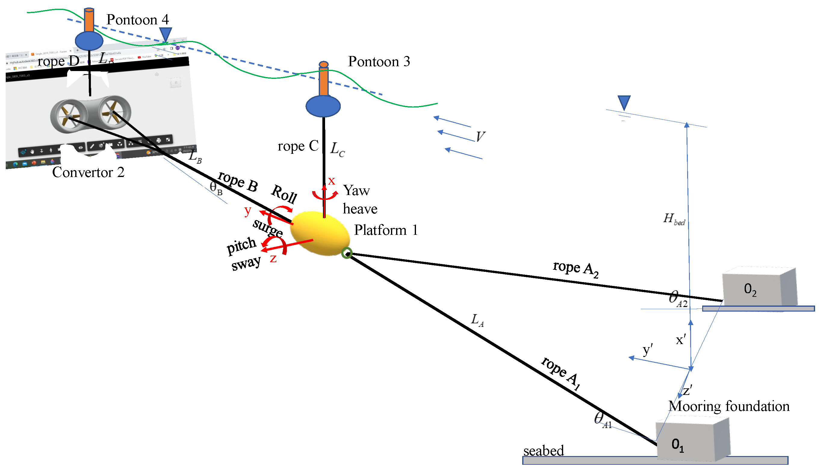
Figure 2.
Top view of the mooring system of ocean energy convertor.
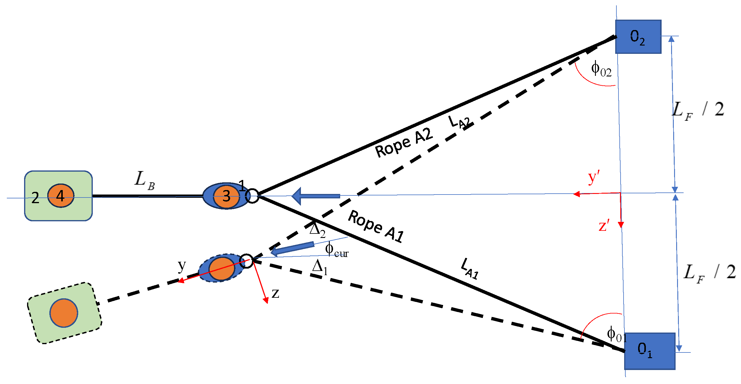
Figure 3.
relation between the directions of invertor and current.
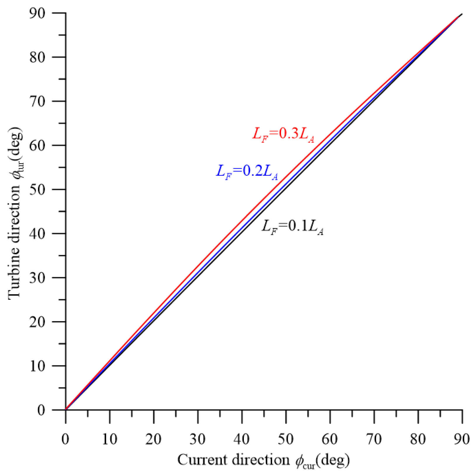
Figure 4.
effect of current direction on tension of rope A.
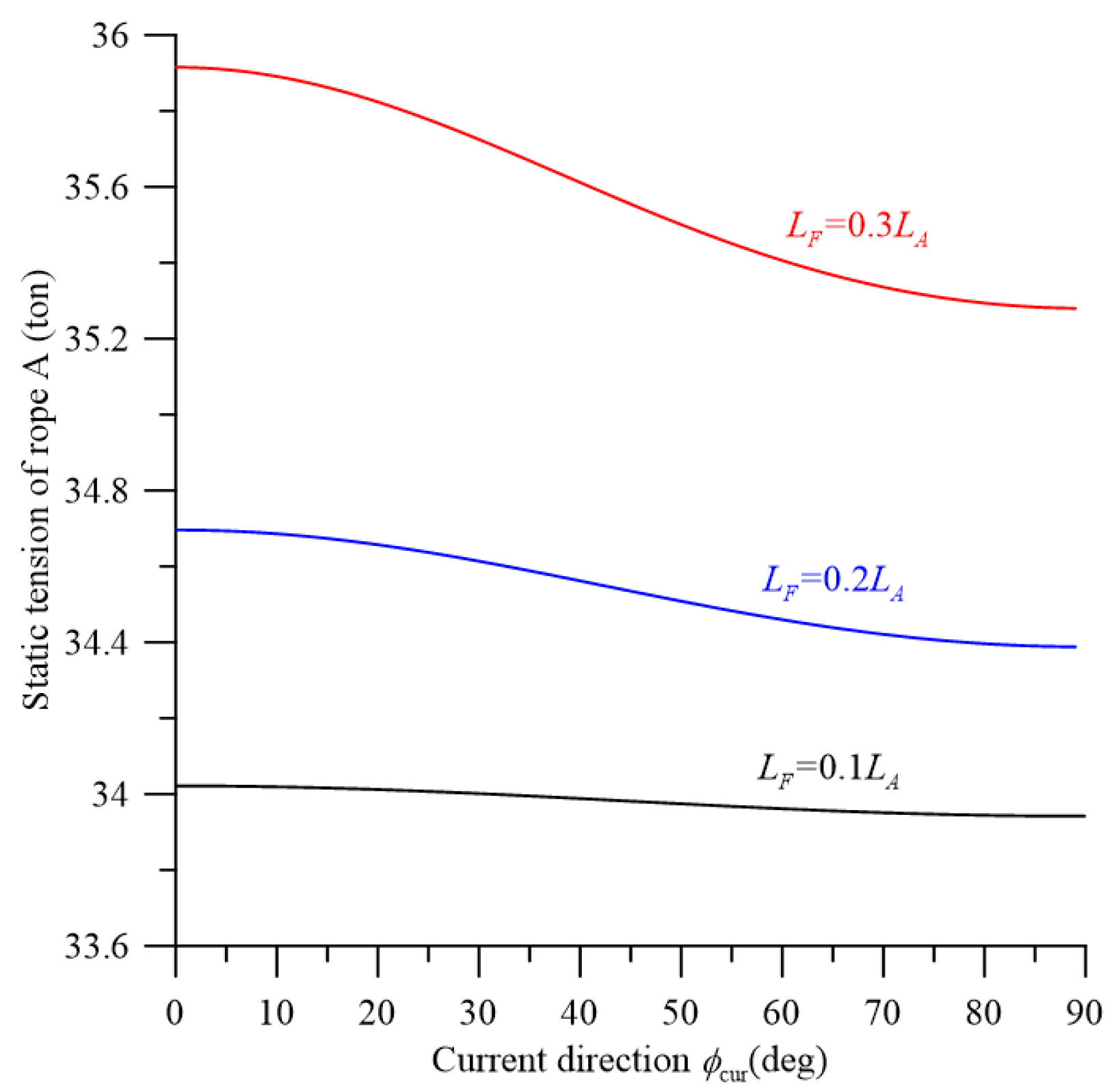
Figure 5.
top view of mooring system under wave and current.
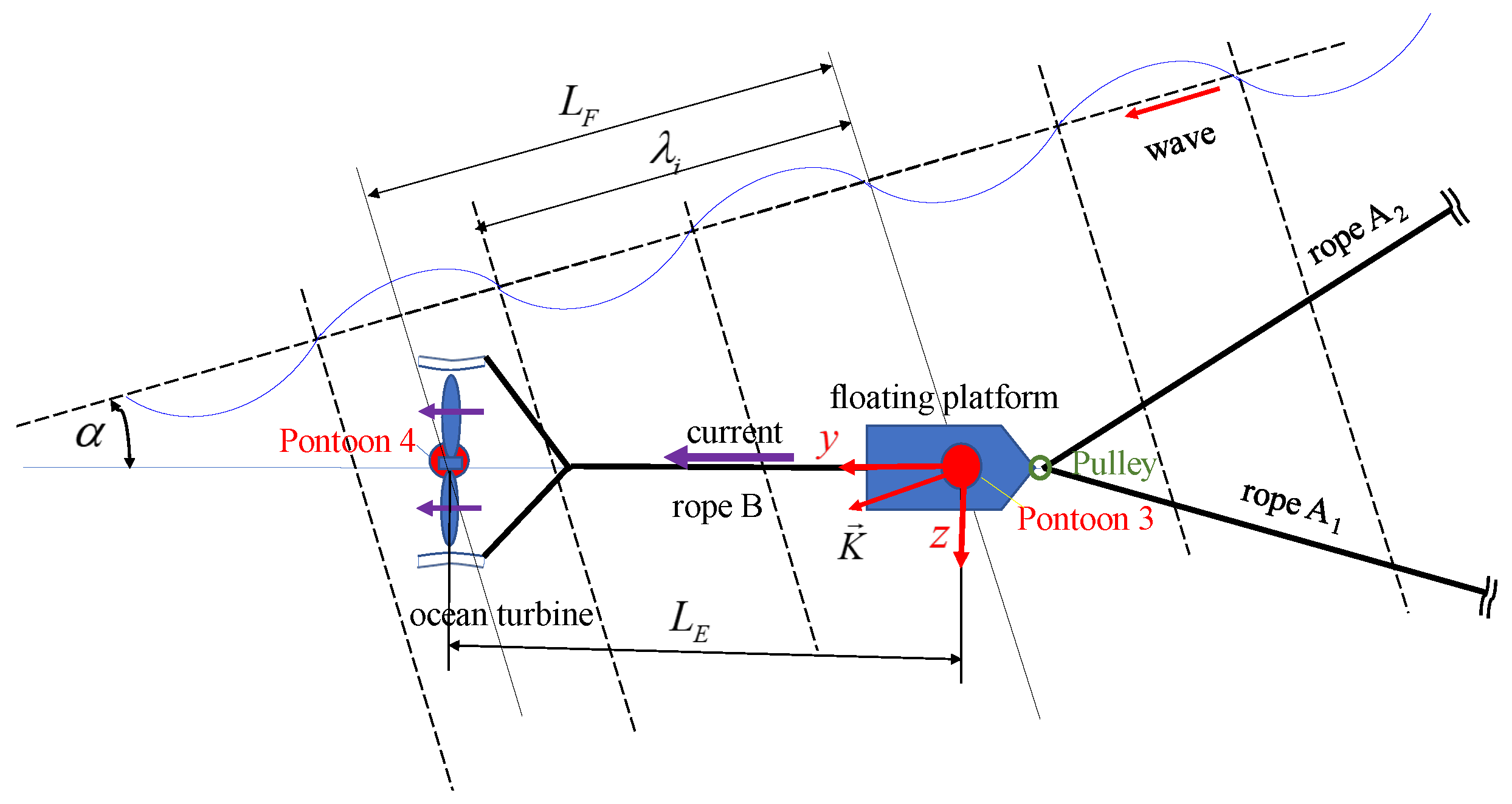
Figure 6.
the relation between the significant height Hs and the amplitudes of six regular simulating waves ai.
Figure 6.
the relation between the significant height Hs and the amplitudes of six regular simulating waves ai.
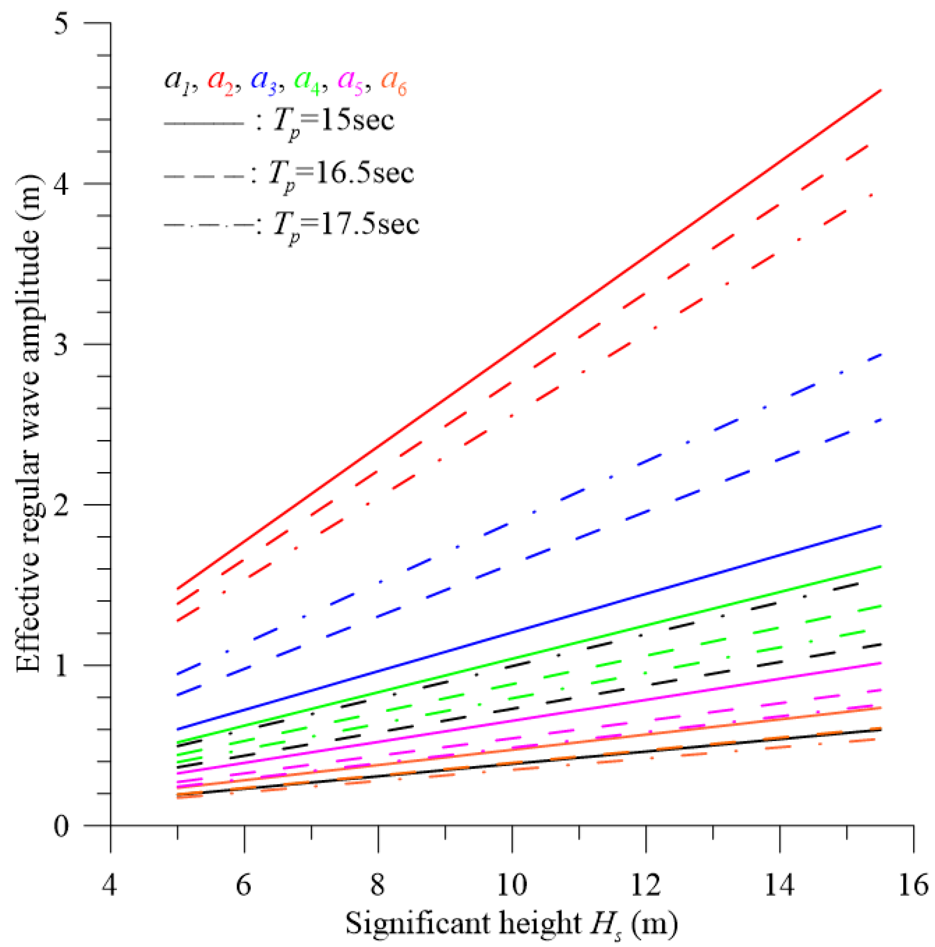
Figure 7.
effects of the distance of two foundations LF and the current direction on the maximum rope tensions and the displacements of elements.
Figure 7.
effects of the distance of two foundations LF and the current direction on the maximum rope tensions and the displacements of elements.
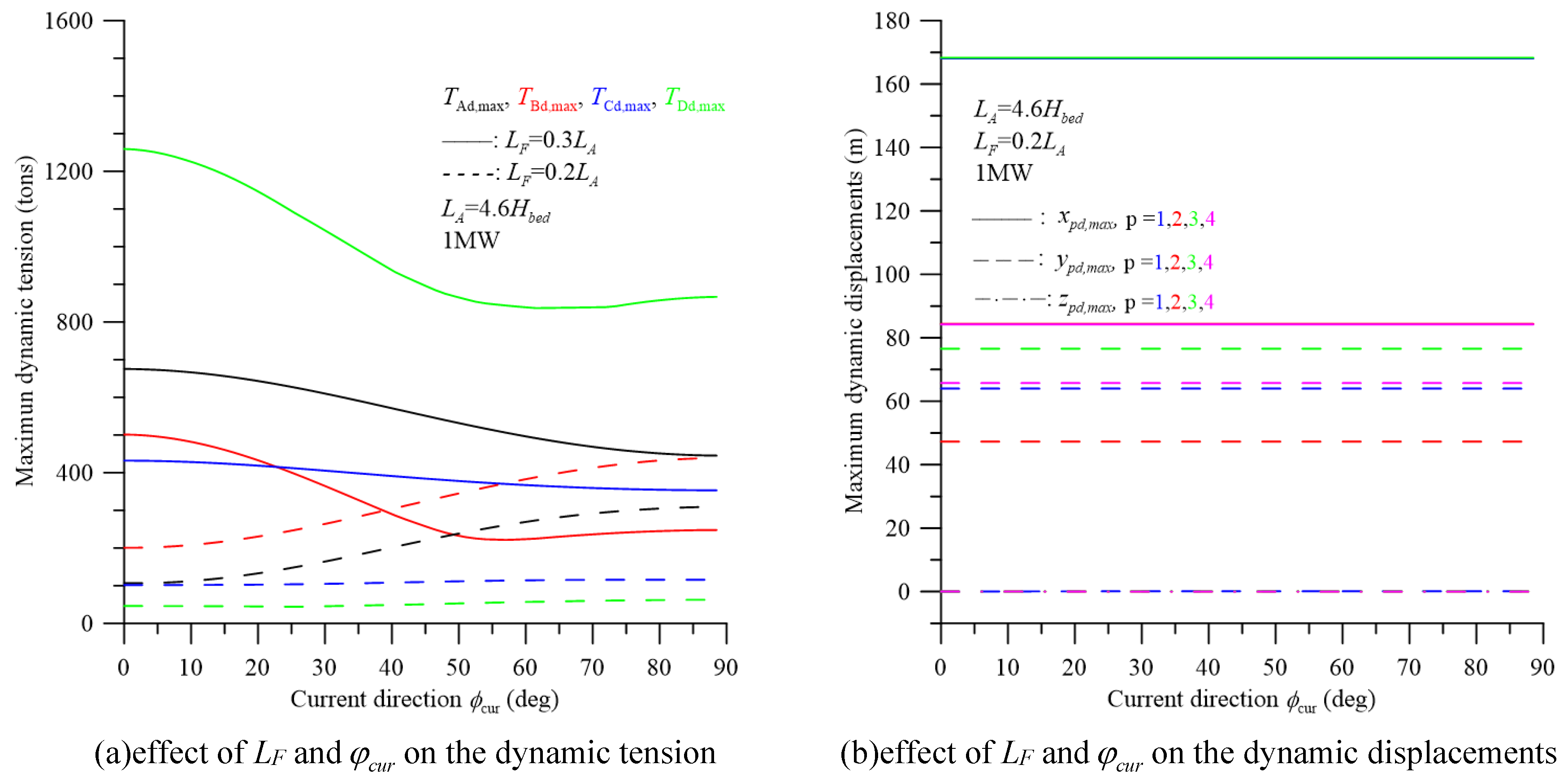
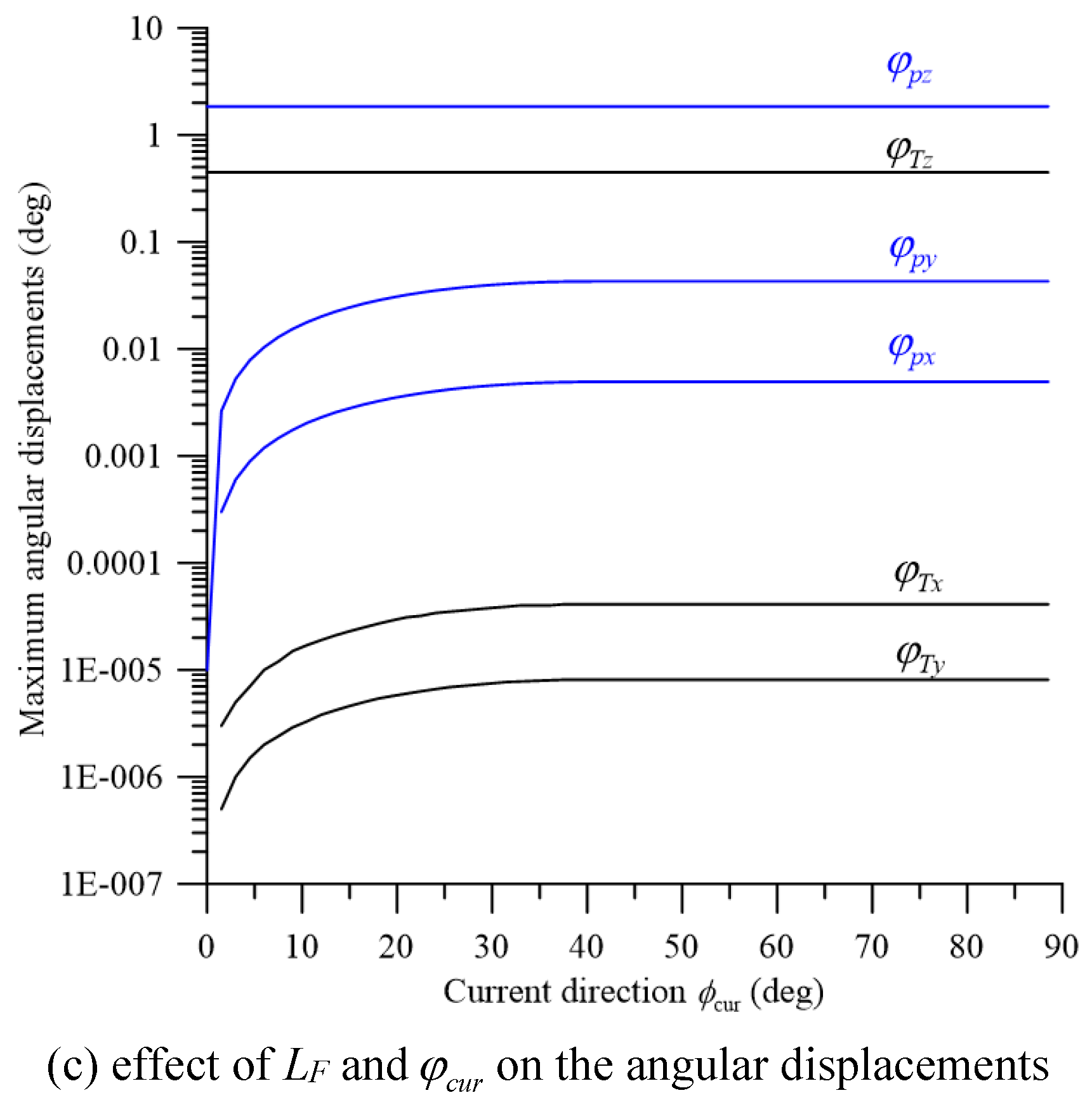
Figure 8.
comparison of the dynamic tensions of two mooring systems with a single rope A and a pulley-rope design.
Figure 8.
comparison of the dynamic tensions of two mooring systems with a single rope A and a pulley-rope design.
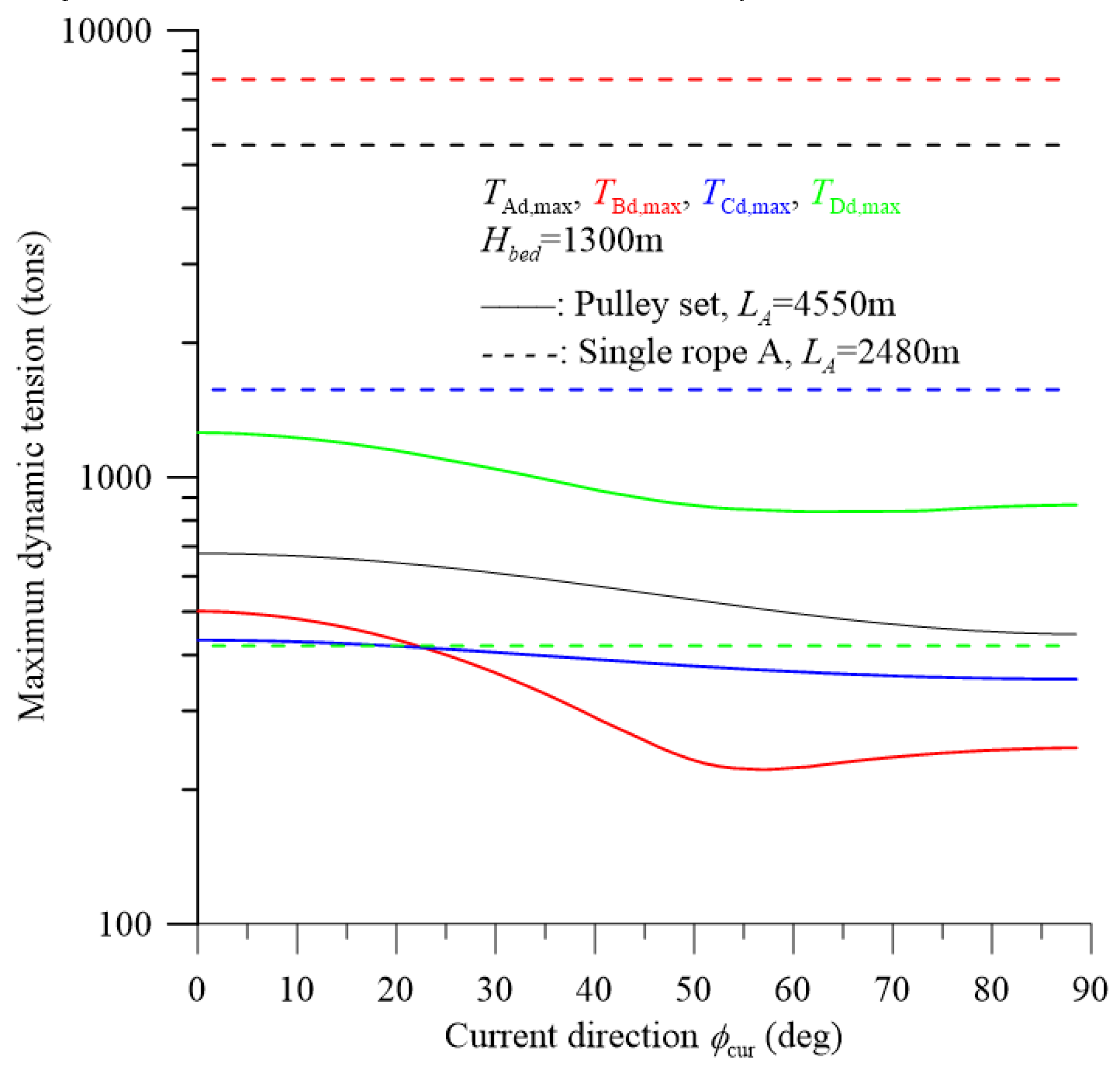
Figure 9.
effects of the length of rope A, LA and the current direction on the maximum rope tensions.
Figure 9.
effects of the length of rope A, LA and the current direction on the maximum rope tensions.
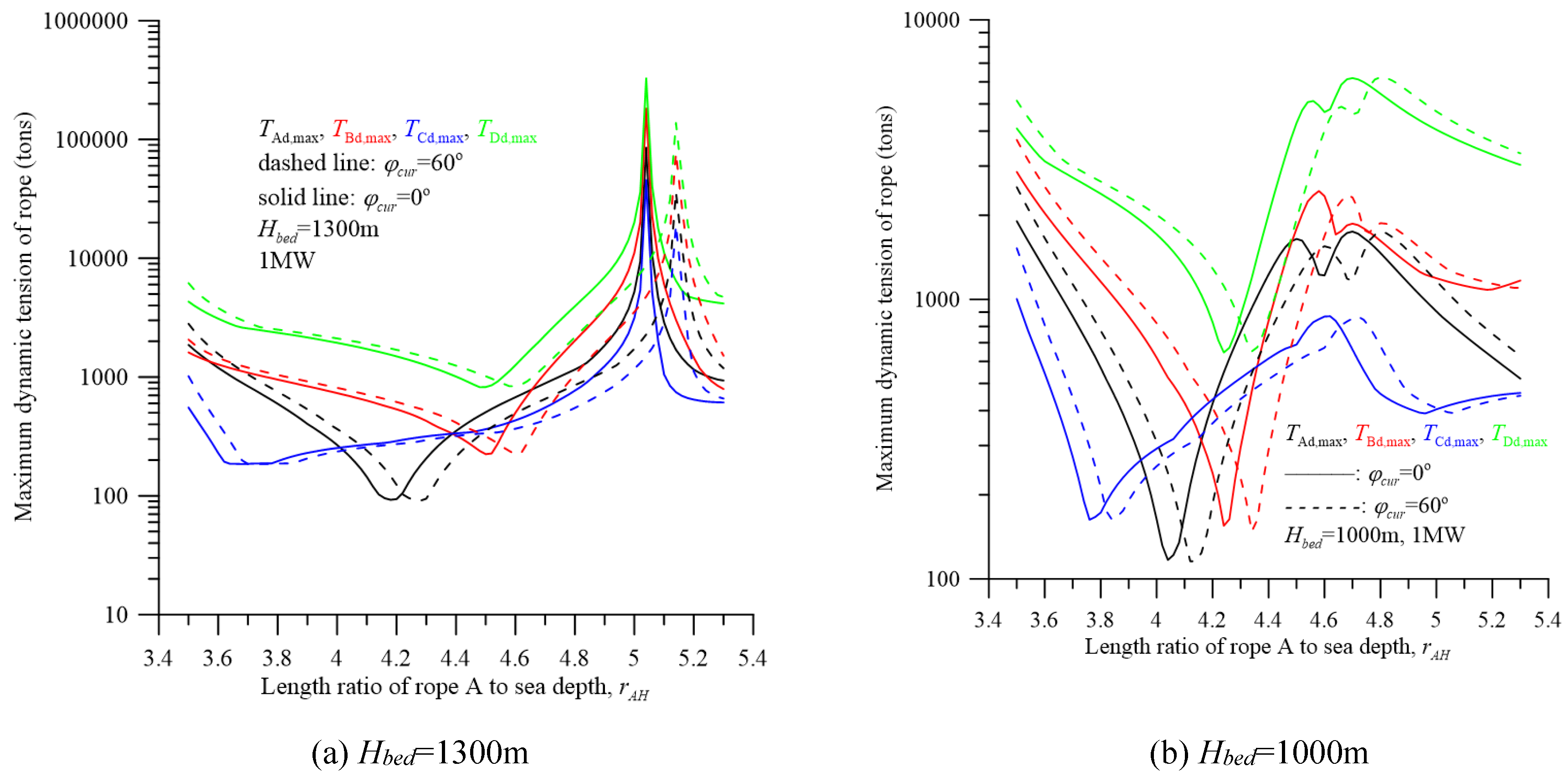
Figure 10.
effect of buffer spring for 1 MW convertor.
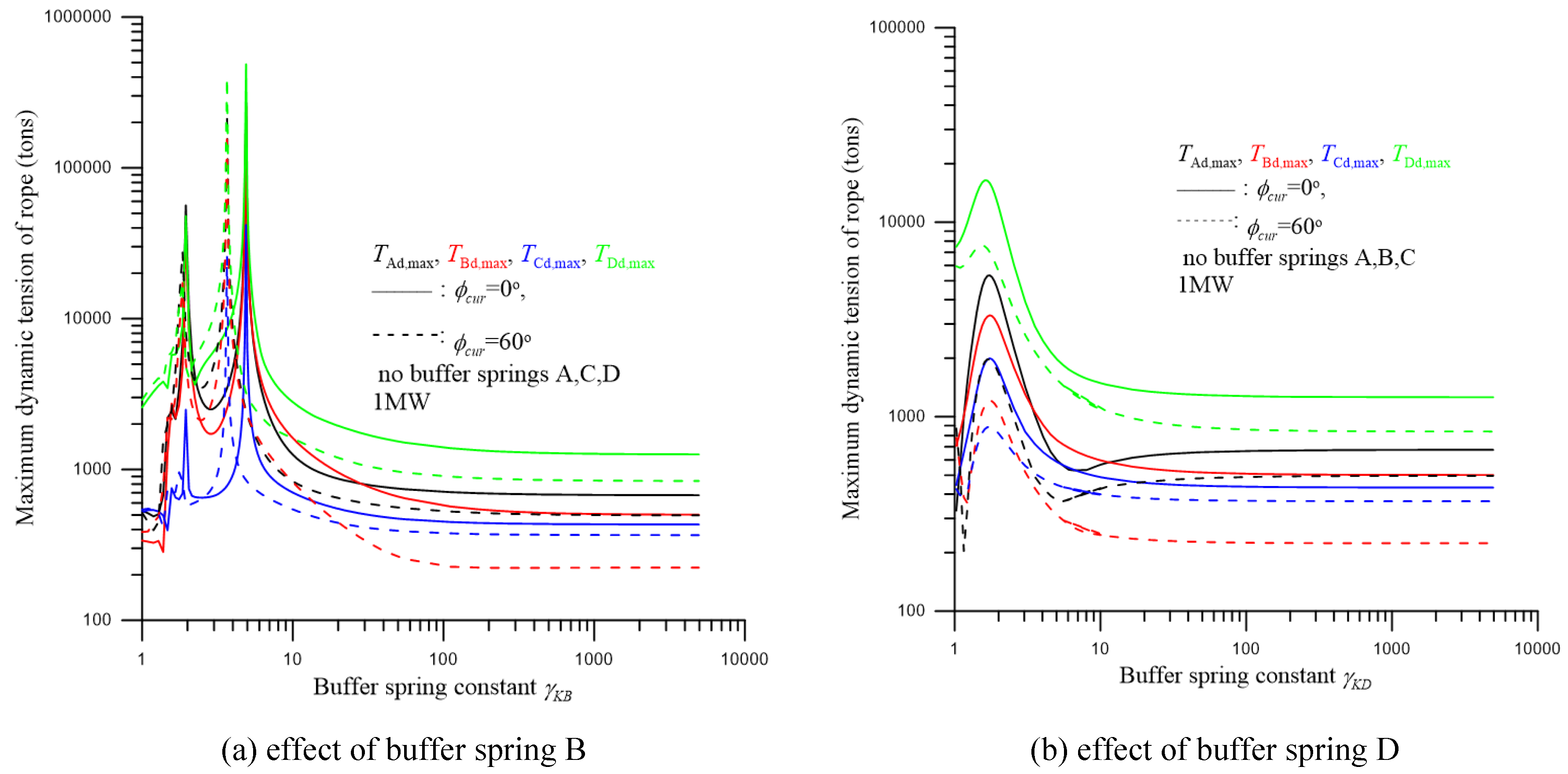
Figure 11.
effect of buffer spring for 700kW convertor.
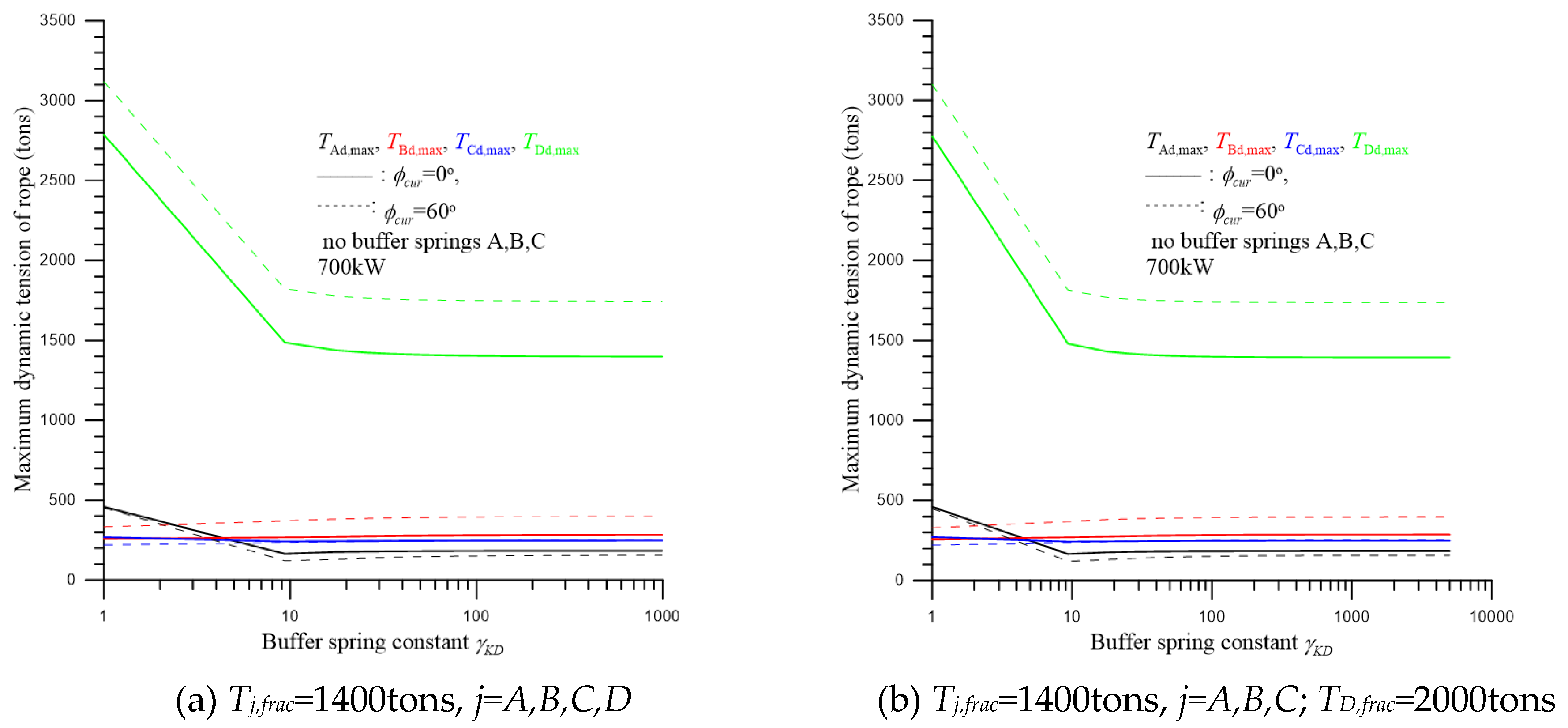
Figure 12.
Top view of mooring system.
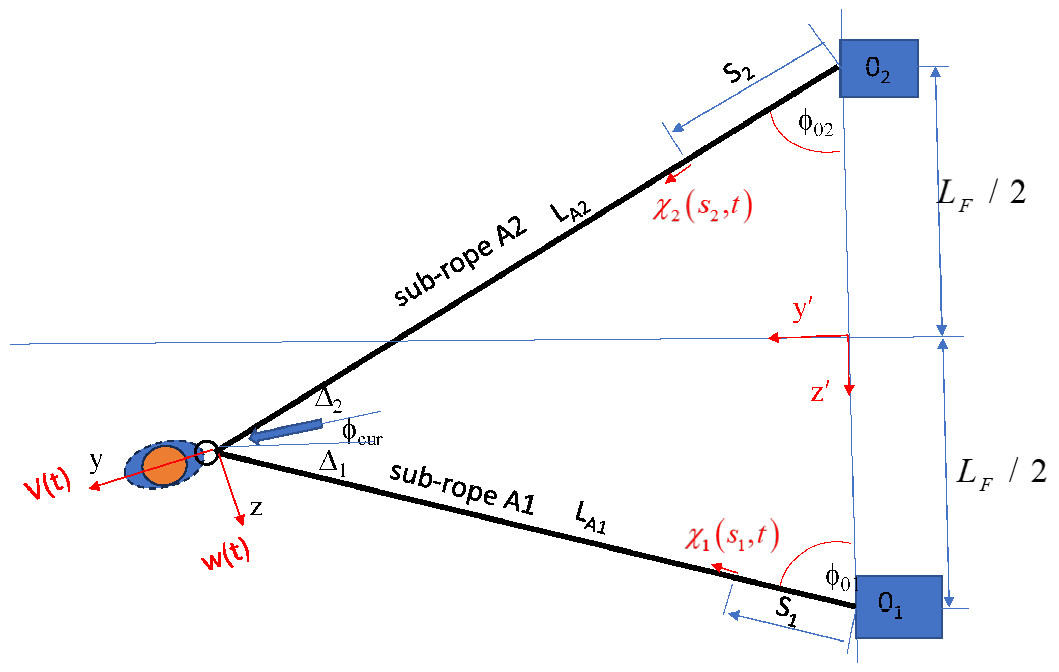

Table 1.
the parameters of the system.
| parameter | dimension | parameter | dimension |
|---|---|---|---|
| depth of seabed Hbed | 1300m | current velocity V | 1.5m/s |
| length of rope A, LA | 5200m | length of rope B, LB | 170m |
| length of rope C, LC | 60m | length of rope D, LD | 140m |
| Static drag of the invertor FDT | 59.35 tons | Static drag of the platform FDB | 0.077 tons |
Table 2.
Irregular wave simulated by six regular waves (Hbed=1300m).
| Significant frequency | Parameter | Regular wave | |||||
| 1 | 2 | 3 | 4 | 5 | 6 | ||
|
Tp =15.0s, fp =0.067Hz |
fi(Hz) | 0.043 | 0.067 | 0.092 | 0.115 | 0.150 | 0.267 |
| ki(1/m) | 0.0073 | 0.0179 | 0.0339 | 0.0533 | 0.0906 | 0.2861 | |
| li(m) | 863.6 | 350.9 | 185.6 | 117.9 | 69.3 | 22.0 | |
|
Tp =16.5s, fp =0.061Hz |
fi(Hz) | 0.043 | 0.061 | 0.086 | 0.115 | 0.150 | 0.267 |
| ki(1/m) | 0.0073 | 0.0148 | 0.0295 | 0.0533 | 0.0906 | 0.2861 | |
| li(m) | 863.6 | 424.7 | 212.8 | 117.9 | 69.3 | 22.0 | |
|
Tp=17.5s, fp=0.057Hz |
fi(Hz) | 0.043 | 0.057 | 0.082 | 0.115 | 0.150 | 0.267 |
| ki(1/m) | 0.0073 | 0.0132 | 0.0272 | 0.0533 | 0.0906 | 0.2861 | |
| li(m) | 863.6 | 477.6 | 231.2 | 117.9 | 69.3 | 22.0 | |
| (o) | 30 | 60 | 90 | 120 | 170 | 300 | |
Table 3.
parameters of the system of 1 MW convertor.
| Parameter | Dimension | Parameter | Dimension | |
|---|---|---|---|---|
| depth of seabed Hbed | 1300m | length of rope A, LA | 5980m | |
| length of rope B, LB | 152.97m | length of rope C, LC | 100m | |
| length of rope D, LD | 70m | distance between two foundations, LF | 1196m | |
| current velocity V | 1.5m/s | net buonyance of invertor and platform FBNT/ FBNB | 1543.6/689.2tons | |
| static drag of the invertor FDT | 148.3 tons | static drag of the platform FDB | 0.192 tons | |
| mass of the platform M1 | 790.6 tons | mass of the invertor M2 | 2126.6 tons | |
| mass of the pontoon 3, M3 | 395.3tons | mass of the pontoon 4, M4 | 474.3tons | |
| cross-sectional area of surfaced cylinder of pontoon 3, ABX | 5.75m2 | mass moment of inertia of the convertor about the x, y, z-axis, |
/ |
|
| cross-sectional area of surfaced cylinder of pontoon 4, ABT | 5.75m2 | mass moment of inertia of the platform about the x,y,z-axis, | / | |
| significant wave height Hs | 15.4m | significant period Tp | 16.5s | |
| relative angle between current and wave a | 30o | phase angles of six regular simulating the irregular wave | 30/60/90/120/170 /300o | |
| HMPE / Dyneema® SK75 |
Young’s modulus EPE | 116GPa, | distance from gravities of platform and convertor |
|
| weight per unit length wPE | 24.47kg/m | |||
| diameter DPE | 178.9mm | |||
| cross sectional area APE | 0.0251m2 | |||
| fracture strength Tfrac | 2000tons | |||
Table 4.
the parameters of the system of 700kW convertor.
| Parameter | Dimension | Parameter | Dimension | |
|---|---|---|---|---|
| depth of seabed Hbed | 1300m | length of rope A, LA | 5980m | |
| length of rope B, LB | 152.97m | length of rope C, LC | 100m | |
| length of rope D, LD | 70m | distance between two foundations, LF | 1196m | |
| current velocity V | 1.5m/s | net buonyance of invertor and platform FBNT/ FBNB | 907.4/407.9tons | |
| static drag of the invertor FDT | 103.9 tons | static drag of the platform FDB | 0.134 tons | |
| mass of the platform M1 | 463.0 tons | mass of the invertor M2 | 1245.5 tons | |
| mass of the pontoon 3, M3 | 213.5tons | mass of the pontoon 4, M4 | 277.8tons | |
| cross-sectional area of surfaced cylinder of pontoon 3, ABX | 4.03m2 | mass moment of inertia of the convertor about the x, y, z-axis, |
/ |
|
| cross-sectional area of surfaced cylinder of pontoon 4, ABT | 4.03m2 | mass moment of inertia of the platform about the x,y,z-axis, | / | |
| significant wave height Hs | 15.4m | significant period Tp | 16.5s | |
| relative angle between current and wave a | 30o | phase angles of six regular simulating the irregular wave | 30/60/90/120/170 /300o | |
| HMPE / Dyneema® SK75 |
Young’s modulus EPE | 116GPa, | distance from gravities of platform and convertor |
|
| weight per unit length wPE | 17.16kg/m | |||
| diameter DPE | 149.7mm | |||
| cross sectional area APE | 0.0176m2 | |||
| fracture strength Tfrac | 1400tons | |||
Disclaimer/Publisher’s Note: The statements, opinions and data contained in all publications are solely those of the individual author(s) and contributor(s) and not of MDPI and/or the editor(s). MDPI and/or the editor(s) disclaim responsibility for any injury to people or property resulting from any ideas, methods, instructions or products referred to in the content. |
© 2024 by the authors. Licensee MDPI, Basel, Switzerland. This article is an open access article distributed under the terms and conditions of the Creative Commons Attribution (CC BY) license (http://creativecommons.org/licenses/by/4.0/).
Copyright: This open access article is published under a Creative Commons CC BY 4.0 license, which permit the free download, distribution, and reuse, provided that the author and preprint are cited in any reuse.