Submitted:
14 July 2024
Posted:
16 July 2024
You are already at the latest version
Abstract
This paper presents a novel approach to designing beam codebooks for downlink multiuser hybrid multiple input multiple output (MIMO) wireless communication systems, leveraging multi-agent reinforcement learning (MARL). The primary objective is to develop an environment-specific beam codebook composed of non-interfering beams, learned by cooperative agents within the MARL framework. Machine learning (ML) based beam codebook design for downlink communications have been based on channel state information (CSI) feedback or only reference signal received power (RSRP) consisting of an offline training and user clustering phase. In massive MIMO, the full CSI feedback data is of large size and is resource-intensive to process, making it challenging to implement efficiently. RSRP alone for a stand-alone base station is not a good marker of the position of a receiver. Hence, in this work, uplink CSI estimated at the base station along with feedback of RSRP and binary acknowledgment of the accuracy of received data is utilized to design the beamforming codebook at the base station. Simulations using sub-array antenna and ray-tracing channel demonstrate the proposed system’s ability to learn topography-aware beam codebook for arbitrary beams serving multiple user groups simultaneously. The proposed method extends beyond mono-lobe and fixed beam architectures by dynamically adapting arbitrary shaped beams to avoid inter-beam interference, enhancing overall system performance. This work leverages MARL’s potential in creating efficient beam codebooks for hybrid MIMO systems, paving the way for enhanced multiuser communication in future wireless networks.
Keywords:
massive MIMO
; millimeter wave
; hybrid beamform
; multi-agent
; reinforcement learning
; beamforming
1. Introduction
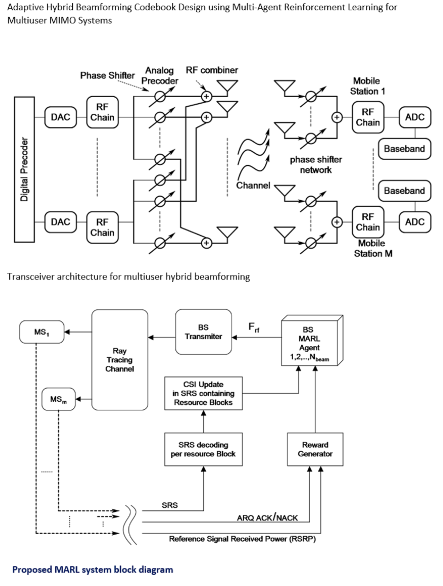
Hybrid beamforming with quantized phase shifters is essential for multiuser MIMO wireless communication systems. The large antenna arrays in millimeter wave (mmWave) MIMO systems are ideal for beamforming. Fully digital beamforming, while optimal, is expensive, computationally demanding, and power-intensive due to the required RF chains.
Hybrid beamforming merges analog and digital techniques for efficient signal transmission using compact, cost-effective quantized phase shifters. These phase shifters adjust the signal phase at the antenna level, improving signal quality. Analog weights form beams toward user groups, and digital weights handle MIMO tasks like interference cancellation within the groups. Hybrid setups with fully connected subarray antennas can produce multiple simultaneous beams, with phase-shifting states controlled by digital circuits for real-time adaptation. This integration offers practical, near-optimal performance in modern wireless systems [1].
Efficient performance in multi-user mmWave systems involves serving multiple user equipments (UEs) from each base station (BS) simultaneously. Precoding multiplexes different data streams to different users. However, fully digital baseband beamforming is impractical for multi-stream mmWave systems due to high costs and power consumption [2].
In mmWave systems, the large number of antennas and very low signal-to-noise ratio (SNR) before beamforming make it impractical to obtain full CSI for conventional closed-loop precoding matrix calculations [3]. Therefore, alternative beamforming and precoding techniques are necessary to achieve efficient performance while managing cost, power, and CSI availability.
Hybrid precoding enables multiplexing multiple data streams by dividing processing between analog and digital domains [4,5]. For example, low-complexity hybrid precoding algorithms exploit the sparse nature of mmWave channels using basis pursuit algorithmic concepts, assuming channel knowledge [4]. Similarly, low-complexity hybrid beamforming algorithms for single-user single-stream MIMO-OFDM systems aim to maximize received signal strength or sum-rate over different sub-carriers [6]. However, these algorithms were designed for single-user channels, limiting supported streams. In multi-user systems, digital precoding in hybrid setups can design precoders that reduce interference between users, making the development of near-optimal, low-complexity hybrid precoding algorithms for multi-user mmWave systems particularly important.
Large antenna arrays with quantized phase shifters have challenges. These phase shifters, with constant modulus, control only the phase, limiting applications to equal gain transmission schemes to maximize SNR or diversity gain [7].
Quantized phase shifter with fixed numbers of bits makes the search space for beams very large. For example, there will be beams for a 64 element antenna array with 3 quantization bits. In a multiuser case with 4 RF chains this number will equate to . Finding optimal beams in such a finite but huge space is impractical with exhaustive search or any other traditional technique. Hence, it is a convention to use beam codebook with large numbers of beams pointing at different directions in an effort to maximize gain to the users in that direction. This approach is not optimal as this single lobe beams, which are matched filters to the array responses in a particular angle, is not guaranteed to offer maximum possible gain for occluded, non-line of sight (nLOS) users. Also, large numbers of beams required in such codebook renders the beam training inefficient and time consuming and hence is inapplicable to mobile users. Additionally, accurate array response is required to form such beemsteering codebook which may not be available for cost effective systems as calibrating antenna arrays is a sophisticated and costly process.
Both artificial intelligence (AI) and non-AI methods have been explored to find optimal beamforming codebooks. A benchmark work [8] used deep learning (DL) to find optimal codebooks for transmit beamforming and combining at user terminals, though it required channel matrix information at both training and prediction phases. Reinforcement learning (RL) offers a promising solution by eliminating the need for offline training phases of static deep networks and facilitating adaptive, situation-aware systems capable of learning from the environment. Significant works, such as [9], have implemented RL-based systems with Wolpertinger-variant architectures for beam codebook design, preceded by beam-clustering to reduce codebook size. Beam clustering in this implementation is actuated through sensing beams. Author in [10] combined radar-aided DoA and DoD estimation and CS basd position estimation with hybrid beamforming for vehicular communication systems, emphasizing accurate direction estimation to improve beamforming efficiency. In this work author has eliminated CSI estimation feedback completely by using the radar-based subsystem. Hybrid beamforming solutions for multi-user millimeter-wave heterogeneous networks is developed in [11] where orthogonal matching pursuit based analog beamforming and minimum mean square error (MMSE) based digital beamforming is used.
To support multiple simultaneous users, proposed work extends [9] by introducing MARL. MARL is an AI research area involving the development of intelligent agents that cooperate or compete to achieve common or individual goals. In a fully cooperative stochastic game, all agents share the same goal and work together to achieve it. Stochastic games involve uncertain action outcomes, with outcome probabilities depending on the current game state. In fully cooperative settings, centralized MARL is generally preferred for effective action coordination among agents. In this work, agent coordination translates to reducing interference between beams serving different user groups simultaneously. Interference between users within a group served by a single beam is minimized through baseband precoding.
The authors in [9] utilized receiver signal strength (beamforming gain) for user clustering and codebook learning. Although this metric simplifies the design, it underperforms in nLOS environments and with user mobility. The computation of average spatial autocorrelation functions for individual multipath components in the mmWave band at 28 GHz revealed that signals reach zero correlation after approximately two wavelengths in LOS environments and after approximately five wavelengths in nLOS environments [12]. This unreliability of signal strength alone challenges the learning agent’s ability to gather useful environmental information.
Motivated by the fact that the environment changes infrequently, computation power and time are traded for accuracy by utilizing uplink CSI estimated at the base station, with re-clustering required only when the environment changes. CSI provides good autocorrelation properties and is relatively immune to hardware imperfections in the RF stage, making it suitable for beam learning applications. Perfect CSI is not assumed, as the channel is seen through the RF lens in hybrid beamforming. However, it is shown in this work that beam learning can be efficiently achieved even with uplink CSI estimates at the BS, by using uplink channel envelope estimates at the BS as fingerprints of specific user locations within the MARL framework.
The agent architecture in [9] is adopted for each RL agent in the proposed design. The Wolpertinger-variant structure adapts the continuous action space of Deep Deterministic Policy Gradient (DDPG) to work with large discrete action spaces [13]. Multi-Agent Deep Deterministic Policy Gradient (MADDPG) is used to train the agents. MADDPG is designed for multi-agent systems, maintaining local actor and critic networks for decision-making and action evaluation. During training, agents share experience replay buffers and learn from collective experiences to enhance their policies. This combination of centralized training and decentralized execution enables agents to learn effective strategies in complex multi-agent environments.
An RF codebook design approach for hybrid precoding algorithms in downlink multi-user mmWave systems is presented, demonstrating efficiency and effectiveness in mobile user environments. The proposed method does not require CSI feedback but learns the downlink beam codebook from RSRP feedback and CSI estimates for uplink sounding reference signals (SRS). By using uplink CSI from SRS as fingerprints for specific user locations, only sub-band sounding is needed. This increases the SNR at the base station, facilitating cell edge UE recovery. The proposed system replaces traditional fixed codebook beams with learned beams that adapt to the environment in an online process. The goal of this proposed work is to create a robust beamforming codebook for the base station in downlink communication, accommodating uncertain user locations even in mobile scenarios. The contributions from the proposed work is summarized as follows:
- A multiuser hybrid mmWave MIMO system model designed as a fully cooperative stochastic game under constraint of quantized RF phase shifters is proposed. A novel algorithm is developed to realize this model. By employing MADDPG to train DDPG (Wolpertinger variant), this approach effectively minimizes interference among simultaneous users, preventing overlapping beams. Unlike previous methods such as [9], this work uniquely addresses and mitigates potential interference between nearby beams with arbitrary shapes, ensuring unparalleled performance and reliability in beamforming for multiuser communication systems.
- A reward function for the RL agent is proposed, considering the comprehensive performance of the end-to-end communication system. The reward for each agent is based on RSRP and binary ARQ status, indicating whether a particular sub-frame scheduled for a specific user is successfully received (ACK) or not (NACK). This method allows the RL agent to maximize successful transmission rates by improving beamforming gain and reducing interference among simultaneous user groups. The cumulative reward function is optimized by MADDPG, enhancing overall system efficiency and reliability.
- The proposed system is rigorously evaluated through simulations using a realistic ray tracing channel model. This comprehensive testing spans various SNR and different codebook sizes. The results demonstrate the system’s robustness and efficiency, highlighting its adaptability and performance across diverse conditions.
Simulation results demonstrate that the proposed method can create optimized beam patterns without needing feedback from downlink CSI, relying instead on RSRP, binary ARQ status, and periodic channel estimates from small sub-band within SRS sub-frames. This deep reinforcement learning-based method efficiently selects beams for the downlink RF codebook, requiring occasional updates, typically when there’s a significant change in the operating environment or the base station’s position. The following sections delve into detailed discussions of the proposed systems, methods, algorithms, and results.
2. Proposed Approach
The proposed multiuser system model is depicted in Figure 1, wherein a mmWave MIMO base station, equipped with antennas and RF chain, is in communication with M simultaneous users each having antennas and one RF chain through streams. Since, each UE is assumed to be served by only one downlink stream and contains only one RF chain, analog combining is applied at the UE. This configuration is similar to works in [3]. The base station utilizes hybrid beamforming, employing a network of r-bit quantized phase shifters.
The decision to employ a single RF chain per UE is motivated by practical considerations, aiming for lower complexity, cost, and power consumption. Conversely, the BS is equipped with advanced digital signal processing (DSP) capabilities designed to handle multiple data streams effectively.
BS attaches with each UE via one stream. This leads to a total of streams, where M represents the maximum number of simultaneous users the BS can serve at once. This aligns with the count of RF chains at the BS (), possible through hybrid schemes enabling spatial multiplexing and multi-user MIMO. This grants the BS the ability to communicate concurrently with multiple UEs using several beams. Design of the end to end communication system is shown in Figure 2. Parameter for each processing block in Figure 2 is shown in Table 1.
In consideration of operational efficiency and hardware constraints, beamforming codebooks are commonly resorted to in mmWave and massive MIMO systems to effectively accommodate users. The sum rate achievable across all UEs is optimized using MADDPG in the proposed approach. Through MADDPG, the RF codebook at the base station is estimated. Represented as W, the beam codebook chosen by the base station consists of N beamforming and combining vectors, each crafted in accordance with the structure outlined in Equation (1).
In this context, each phase shift is chosen from a finite set S containing discrete values, uniformly selected from the range of (). Here, the parameter r represents the number of quantization bit used in phase shifters.
The BS employs baseband precoding denoted as to process the transmit signal in compliance with , assuming uniform power distribution among users. Notably, P signifies average power. RF precoders , constructed using phase shifters, are utilized to direct the signal to transmit antennas. Moreover, considering consists of analog phase shifters, constant equal-norm components in the RF precoder is assumed, i.e., . Furthermore, the power constraint is maintained through normalization. Consequently, the transmitted signal comprising of elements is given as
considering be the channel matrix between BS and k user, the received signal for k user for a narrowband block fading channel is given as
Where is the complex additive white Gausian noise (AWGN) with . This signal is received by the k user and is processed by the combiner to get , ie,
Where RF combiners are designed as quantized phase shifter so that
Achievable rate for the k user assuming Gaussian symbol transmission through the channel is given as
Subsequently, the achivable sum rate for the system is given as [8]
In this proposed work, as the beams of the learned codebook is acquired. through conventional beam sweeping is obtained, as detailed in Section 3. The acquisition of occurs in the second step of a two-step procedure, as outlined in [3]. It is important to note that in this proposed work, the focus is solely on learning . The contribution can also be conceptualized as adaptive beam sectoring that is aware of the environment.
2.1. Channel Model
In this work, the ray tracing channel model is employed for simulation purposes. Stochastic channel models lack the spatial detail required for accurate beamforming simulations, making deterministic models like ray tracing preferable for such tasks. Ray tracing channel models treat electromagnetic waves as rays, accounting for interactions like reflection and diffraction with various surfaces in the environment. These models provide detailed insights into signal propagation, aiding in the design and optimization of wireless communication systems
The ray tracing channel model is applied to an OpenStreetMap (.osm) file corresponding to Canary Wharf in London, UK. The latitude and longitude coordinates (, ) specify the BS location. The map is sourced from https://www.openstreetmap.org, providing crowd-sourced map data worldwide. Loaded into MATLAB for ray tracing simulation, the map defines transmitter and receiver sites. Multiple receivers are initialized with respective positions, simulating non-stationary users traversing the area. High-rise structures are represented using concrete as the building material.
Figure 3 depicts the ray tracing environment, where one UE experiences LOS conditions while the other encounters nLOS conditions.
3. Beam Learning with MARL
The codebook learning process is initiated by first obtaining a fixed conventional codebook through the initial access procedures and beam management procedures outlined in the 5G New Radio (5GNR) technical report. The steps involved in this fixed codebook learning process are summarized as follows:
Procedure 1 : When a connection is established between a transmitter and a receiver, an initial beam alignment is required. This involves finding an optimal transmit-receive beam pair that maximizes the signal strength between the devices. Various methods like synchronization signal blocks (SSBs) and reference signals are used to aid in this process. This is shown in Figure 4.
Procedure 2 : Refining transmit-end beam via non-zero-power CSI-RS and SRS. After initial beam acquisition, this beam management aims to refine the beams to improve the communication link further. In this step, reference signals are sent in different directions using finer beams within the initial angular range. UE or BS assesses these beams with fixed receive beam and selects best transmit beam.
This proposed system initially employs a standard beamforming procedure and gradually transitions into a more efficient MARL based system over time. This method essentially substitutes standard codebook beams with learned beams on a one-to-one correspondence basis. The angular spacing between nearby beams is determined by the number of beams, which corresponds to the number of agents in the MARL framework. This approach simplifies implementation without necessitating alterations to the existing infrastructure. Once the codebook is learned, it can be utilized until the link’s performance deteriorates due to significant changes in the deployment site.
It is important to note that a learned multibeam codebook differs from simply parallelizing multiple single beams. Unlike fixed codebook beams, learned beams are not matched filters to the antenna array response and can adopt any arbitrary shape suitable for the scattering environment of deployment. Consequently, this may result in beam overlap, leading to inter-user interference, if cooperation between the beams for multiple simultaneous users is not established. The proposed MARL-based approach addresses this issue by cooperatively learning the beamforming vector for each beam per user group.
In this research, the procedures for initial beam acquisition and subsequent beam learning are segmented into the following major steps:
- SSB beam sweeping
- Beam measurement and determination at UE
- Beam reporting to BS by UE
- Send SRS to BS from UE for uplink transmit end beam refinement and also for MARL based downling transmit end beam refinement. This procedure differs from method in 5GNR by the fact that the standard used NZ-CSI-RS for downlink transmit end beam refinement. This requires CSI feedback from UE and can work only with traditional matched filter based codebooks as full channel estimate feedback from UE which is required for non-codebook based beamforming is unavailable or impractical to achieve and resource intensive.
- Send NZ-CSI-RP to UE only to get RSRP feedback (RSRP consumes very little resource).
- Decode received SRS and estimate uplink Channel at BS.
- Send RSRP measurement in SRS to UE for beam refinement at UE.
- At BS, use RSRP and channel estimate acquired in step e and step f to learn downlink transmit end beam codebook through the proposed MARL algorithm.
To make RL, or in this case MARL, applicable, the environment must be modeled as a Markov process. In [9], this is achieved by incorporating the current beamforming vector as a function of the previous beamforming vector. A similar approach as in [9] is followed, extending this method by also considering the partial and imperfect CSI acquired by the BS during uplink SRS transmission by the UE. The operation of the entire system is illustrated in Figure 5, with each processing block and signal flow explained subsequently.
3.1. Details of MARL
The proposed MARL algorithm builds upon the Wolpertinger Architecture [13], following a similar approach as described in [9]. The Wolpertinger Architecture adapts the DDPG, originally crafted for continuous action spaces, to function within a discrete action space through the utilization of a K-nearest neighbor (KNN) classifier. To address non-stationary environment issues in a multi-agent RL system with continuous action spaces, the MADDPG offers a solution. MADDPG achieves this through centralized training and decentralized execution. To accommodate a discrete action space in MARL, an improvisation on MADDPG is made by implementing each agent in MARL using the Wolpertinger Architecture. Thus, the proposed MARL essentially embodies MADDPG, with each agent designed to adhere to the Wolpertinger Architecture.
The proposed beam learning problem presents a significant challenge due to the large number of possible actions. For instance, considering a base station with 32 antennas, 3-bit phase shifters, and 4 RF channels, each agent faces around potential actions. This complexity is further compounded with additional antennas and higher-resolution phase shifters, rendering conventional deep Q-network frameworks impractical.
Additionally, multi-agent deep Q-networks suffer from instability and renders the environment non-stationary. To overcome these limitations, the Wolpertinger architecture is introduced, offering a solution for navigating spaces with extensive sets of discrete actions [13]. This architecture, rooted in the actor-critic framework, is trained using the DDPG algorithm [14]. Notably, the Wolpertinger architecture incorporates a KNN classifier, enabling DDPG to effectively handle tasks with discrete, finite, yet exceptionally high-dimensional action spaces. Below, a concise overview of the key components of the Wolpertinger architecture is provided.
Actor Networks: The actor maps states from the observation space to actions, serving as a function approximator for this mapping process. Since the actions obtained from the actor fall into a continuous action space, the predicted action may not align perfectly with the action space of the problem. Therefore, this prediction is referred to as a proto action and is quantized by a KNN classifier to obtain an action available in the discrete action space.
KNN search: KNN search is employed to determine the nearest neighbor of the proto action within the discrete action space. This algorithm utilizes the distance, also known as squared Euclidean distance, as a metric to identify the closest vector to the proto action. In essence, the KNN algorithm assesses the spatial proximity of the proto action to the available discrete actions, helping to quantize and align the predicted action with the specific options within the discrete action space.
Exploration noise process: Noise helps agents explore the environment more effectively by injecting randomness into their actions. Exploration is essential in reinforcement learning to discover new states and actions that can lead to better policies. Without exploration, agents might get stuck in suboptimal policies. The noise added to actions is often generated from a stochastic process, such as a Gaussian distribution, Ornstein-Uhlenbeck process, or other types of noise sources. Ornstein-Uhlenbeck process is used in this work to generate noise that is added to the actions of an agent. This noise has the property of being temporally correlated, which means that it tends to stay close to its current value over short time intervals, mimicking the behavior of real-world systems. The peak noise magnitude needs to be such that after adding it to the action in element-wise manner produces resultant magnitude large enough to cover the full range of phase shifter array.
Critic Networks: The critic network functions as a Q function, accepting both the state and action inputs and generating the anticipated Q value for the specific state-action combination. Given that the KNN function yields k potential actions, the critic network evaluates k distinct state-action pairs (with a shared state), ultimately pinpointing the action that attains the highest Q value among them.
target Networks: The target network is a separate neural network that mirrors the actor network. It’s parameters are updated less frequently, providing a stable target for the training process. The periodic update of the target network’s parameters enhances the stability and convergence of the learning process, leading to improved training efficiency and more accurate action value estimations.
In this scope, the input (State), outputs (action) and reward process of the MARL algorithm is defined.
State: State comprises of the concatenated vector of the phases of all phase shifter at time t and average normalized envelop of Channel estimate obtained through procedures given in step a through step h of the major steps mentioned at the beginning of this Section 3.
Action: Action comprises element-wise changes of all the phases in the state vector at time t.
Reward: Proper reward design is pivotal for shaping effective RL policies, achieving goals efficiently, and avoiding unintended behaviors. In this proposed work, the reward function is designed to satisfy two goals, namely maximize average beamforming gain in turn maximizing sum rate of the system and reducing inter-beam interference.In the proposed approach, the end-to-end system is implemented, where the ARQ signal is sent by the UE to the BS based on whether a frame was received correctly or not, and the received ARQ is also used as an input for reward modeling, addressing concerns that RSRP alone may provide a misleading indication of beamforming gain maximization in a multi-beam system with interference. The proposed reward processing is detailed in Algorithm 1.
| Algorithm 1:Reward Function |
|
Steps of MARL learning for N agents is given as pseudo-code in Algorithm 2.
| Algorithm 2:MARL based beam learning |
|
3.2. Data Preprocessing
The SRS provides the BS with comprehensive channel information across the entire bandwidth. Utilizing this information, the BS optimizes resource allocation, giving preference to areas with superior channel quality over other bandwidth segments. In this proposed work, emphasis was placed on a central cluster consisting of four resource blocks (RBs), each encompassing a bandwidth of 180 kHz. Within each RB, 12 subcarriers are positioned at 15 kHz intervals, resulting in a combined bandwidth of 720 kHz. A frequency-domain vector comprising 48 complex numbers is derived through channel estimation across this contiguous frequency range. Given that only a narrow band of the entire spectrum is required for the proposed algorithm, achieving high SNR for SRS transmission is feasible.
For further analysis, this complex vector is transformed into its magnitude and then downscaled by a factor of 2, resulting in a real-valued vector comprising 24 elements. To ensure consistency, in the subsequent preprocessing stage, this 24-element vector is normalized by dividing it by its maximum value. This procedure is iterated for each of the four simultaneous users, producing four channel vectors.
The other part of the state vector input consists of the phases of the phase shifter network for a particular RF chain of length which is 32 in this case. This is also normalized by the maximum absolute value of the phase vector. Here, four such phase shifter vectors are obtained for four RF chains.
The input to each actor network is the corresponding state. The state is the concatenation of the 24 length channel vector given as and 32 length phase vector which equals . Thus the length of state vectors are which is 56 in this case. The output of the actor networks are also the predicted phase update vectors which is of length , ie, 32. The actor network includes a pair of hidden layers, each containing neurons equating to 560. These layers are subsequently activated using Rectified Linear Units (ReLU). The outcome of the actor network stands as the anticipated action. This outcome is then passed through hyperbolic tangent (tanh) activations, which are scaled by .
Thus the length of the input of each critic network for a 4 agents can be given as , ie 336 in this case. The output of the critic network is the predicted Q value, which is a real valued scalar. hence, output dimension of critic network is 1. The critic network is composed of two hidden layers, each layer containing , ie, 1680 neurons. Following this, ReLU activations are applied to these layers.
Hyper parameter for the MARL is given in Table 2.
3.3. System Level Simulation with MARL
In this proposed work, a sector of a cell for simulation purposes is modeled, restricting transmissions within this azimuth range. Although the 4 RF channels can concurrently serve 4 users within this angular space, real-world scenarios typically involve more than 4 active users. To address this, users with similar channels are served with a single beam. The assignment of each user to a specific beam, whether before or after the MARL-based codebook learning process, is determined through beam sweeping. Consequently, the number of beams in the learned codebook remains consistent with the initial access codebook, which is adjustable for performance assessment. Figure 6 illustrates the radiation pattern for one such codebook with 9 beams, showcasing variations for different quantization bits.
In the proposed MARL algorithm, the number of agents corresponds to the number of beams utilized in the sector. This configuration effectively breaks down the task of selecting a beam from a large set into finding a single beam within a smaller subset, thereby enhancing the efficiency of the codebook learning process. An additional and significant benefit of employing one agent per beam is the ability to identify optimal non-interfering beams within the sector, even in nLOS scenarios. Each agent in the MARL algorithm strives to maximize individual beamforming gain while minimizing interference with other agents, as reflected in the reward processing outlined in Algorithm 1.
Upon completion of the learning phase, the acquired codebook becomes readily deployable within the initial access procedure. Users can now be efficiently served using the learned codebook, rendering the traditional matched filter-based beam codebook obsolete. This transition marks a significant advancement in the efficiency and adaptability of beamforming techniques, as the learned codebook optimally caters to the dynamic needs and complexities of the communication environment without relying on pre-defined beam patterns.
This learned codebook is valid until there is no significant change in terms of macro structures within the sector. Although such time will be there only occasionally, in case of such large changes in the structure or re-placement of the BS, learning has be initiated again for all the beams.
Next, the analog beamforming codebook selection for the UE is carried out. In this work, a conventional beamforming codebook tailored for the UE is employed. The process of selecting beams from the codebook for the UE involves a standard beam search procedure, encompassing steps such as sounding, measurement, and feedback.
In the final step, the baseband beamforming vector () at the BS is calculated. This computation follows the procedure outlined in [3]. In this process, the BS formulates its zero-forcing digital precoder based on the quantized channel feedback received from the UE. Due to the utilization of RF beamforming and the presence of sparse mmWave channels, it is anticipated that the effective MIMO channel will be well-conditioned [17,18]. This favorable channel condition enables the utilization of a straightforward multi-user digital beamforming strategy like zero-forcing, which can achieve performance close to the optimal level [19]. The algorithm for obtaining the baseband beamforming vector is detailed in the second stage of the procedure presented in [3].
4. Results and Discussion
In this section, the performance of the proposed MARL technique developed is showcased. This is demonstrated through a series of experiments where the network is trained using the parameters outlined in Table 2. The effectiveness of the proposed MARL-based approach to learning beam codebooks across various scenarios is assessed. The task of acquiring a beam codebook with multiple beams for multiuser MIMO, as distinct from creating a codebook for single-user MIMO systems as discussed in [9], involves not only learning the codebook but also identifying optimal combinations from a wide range of potential beamforming vectors.
To address this issue, a straightforward clustering approach based on a simple beam sweeping technique is proposed. Users sharing similar channel characteristics are grouped together and served by a single beam. This approach allows us to learn interference-free arbitrary beams using multiple agents within the MARL framework. Additionally, clustering divides the intricate task of finding beams across the entire azimuth into parallel sub-tasks, making it more manageable and efficient for learning a multi-user, multi-beam beamforming codebook. This simplification streamlines the acquisition process of a codebook comprising multiple beams.
Figure 7 illustrates the average beamforming gain relative to the number of beams contained within the codebook, specifically in the LOS scenario. In this scenario, the Base Station employs a uniform linear array with isotropic elements, oriented in a back-baffled configuration. The graph demonstrates a consistent upward trend in average beamforming gain with an increasing number of beams.
Moreover, in line with the observations made in [9], proposed solution demonstrates nearly equivalent performance to a classical 32-beam beamsteering codebook when employing only 6 beams. Notably, the proposed approach not only matches but also surpasses the performance of [9]. This trend persists as the solution, employing 8 beams, consistently outperforms the 32-beam classical beamsteering codebook while also exceeding the capabilities of [9]. This achievement holds particular significance considering the proposed work addresses a multiuser scenario with 4 cochannel users and nonzero interference probability, representing an improvement over [9], which is designed for a single-user MIMO configuration. It is important to note that traditionally, single-user and multiuser codebooks are identical, meaning multiple beams from the same codebook are used for multiuser MIMO. For this comparison, the single-user codebook learned by deep reinforcement learning (DRL) in [9] is utilized and extended it to the multiuser case.
The proposed methodology illustrates its capability to dynamically adjust beam configurations based on user distributions and environmental topography. This adjustment effectively mitigates interference within densely populated urban environments, leading to notable performance improvements.
Furthermore, users were strategically placed in nLOS areas within the scenario. Simulation under nLOS conditions highlights the superiority of the proposed MARL system compared to traditional beam codebooks and those proposed in [9]. In this scenario, MARL outperforms the 32-beam classical beamsteering codebook and [9] with just 4 beams. Given that only reflected paths of the channel are available in nLOS conditions, this improvement underscores the adaptability of the MARL system to varying environments. The simulation results for MARL under nLOS conditions are depicted in Figure 8.
The performance of MARL is contrasted against various hybrid precoding techniques including manifold optimization (MO) [15], sparse orthogonal matching pursuit (SOMP) algorithm [16], and the two-stage hybrid beamforming (TS-HB) algorithm [3]. Notably, manifold optimization and SOMP were initially proposed for single-user scenarios, but for comparison these algorithms are adjusted to the multi-user context by adopting the interference cancellation strategy outlined in [8]. In the simulation plot for no interference, the outcomes of fully-digital beamforming and combining is traced. This approach effectively eliminates interference, serving as a reference point in the evaluations.
Figure 9 presents a comparative analysis of the achievable sum-rate performance of the algorithms across varying SNR levels. The system parameters are set as follows: antennas per BS, antennas per UE, synthetic noise with an SNR of , and quantization bits. Each user is characterized by paths, with paths per user. This consistent configuration is maintained across all algorithms to ensure a fair comparison.
For reference, fully digital beamforming and the MO algorithm, known for its near-optimal analog and baseband precoders, have been included. Importantly, the performance of the proposed MARL approach closely mirrors that of the MO algorithm, consistently achieving the highest sum-rate among all algorithms.
When assessed against MARL, DRL, SOMP, TS-HB, and convolutional neural network for MIMO (CNN-MIMO) [8] demonstrate relatively inferior performance. While SOMP was originally devised for single-user scenarios, it has been modified for multi-user contexts in this proposed work. Both SOMP and TS-HB necessitate input in the form of feasible sets F and W. Therefore, the precision of these feasible sets significantly impacts the performance of SOMP and TS-HB, relying on the accuracy of both channel matrices and array response sets. While CNN-MIMO doesn’t require feasible sets of beamforming vectors during the prediction stage, it’s necessary during the training stage to acquire labels. Overall, these outcomes underline the robustness of the proposed MARL-based approach in the realm of downlink RF beamforming codebook design in multi-beam and multiuser MIMO systems. To highlight the advantages and differences of each of the studied sachems over one another, a table is formed as given in Table 3.
5. Conclusion
In this proposed work, the challenge of designing adaptable beam codebooks for multiuser mmWave MIMO systems is addressed. These codebooks are required to dynamically adjust to environmental changes and mitigate interference without direct channel feedback. A novel approach is proposed wherein MARL is utilized to optimize downlink transmit beam patterns based on environmental conditions, user distribution, and interference levels. To enhance learning efficiency by breaking down the task into manageable segments, a user clustering technique resembling beam sectorization is integrated. User clustering enables interference avoidance between arbitrary beams in the learned codebook through MARL cooperation. Through extensive simulations using ray tracing channels, the efficacy of the proposed work in learning environment-aware codebooks is validated. The learned codebooks surpass traditional beamsteering methods, achieving performance comparable to unconstrained beamforming vectors with full channel knowledge, even with fewer beams.
Author Contributions
Data curation, Manasjyoti Bhuyan and Debashis Misra; Formal analysis, Kandarpa Sarma; Investigation, Manasjyoti Bhuyan and Koushik Guha; Methodology, Manasjyoti Bhuyan and Kandarpa Sarma; Project administration, Jacopo Iannacci; Software, Debashis Misra; Supervision, Kandarpa Sarma, Koushik Guha and Jacopo Iannacci; Validation, Manasjyoti Bhuyan and Kandarpa Sarma; Visualization, Manasjyoti Bhuyan; Writing – review and editing, Debashis Misra, Koushik Guha and Jacopo Iannacci. All authors have read and agreed to the published version of the manuscript.
Funding
This research received no external funding.
Institutional Review Board Statement
Not applicable.
Informed Consent Statement
Not applicable.
Conflicts of Interest
The authors declare no conflicts of interest.
References
- Molisch, A.F.; Ratnam, V.V.; Han, S.; Li, Z.; Nguyen, S.L.H.; Li, L.; Haneda, K. Hybrid beamforming for massive mimo: A survey. IEEE Communications Magazine. 2017, 55, 134–141. [Google Scholar] [CrossRef]
- Singh, J.; Ponnuru, S.; Madhow, U. Multi-gigabit communication: the adc bottleneck. IEEE International Conference on Ultra-Wideband. 2009, 22–27 pp. 22–27.
- Alkhateeb, A.; Leus, G.; Heath, R.W. Limited Feedback Hybrid Precoding for Multi-User Millimeter Wave Systems. IEEE Transactions on Wireless Communications. 2015, 14, 6481–6494. [Google Scholar] [CrossRef]
- Ayach, O.E.; Rajagopal, S.; Abu-Surra, S.; Pi, Z.; Heath, R.W. Spatially sparse precoding in millimeter wave mimo systems. IEEE Transactions on Wireless Communications. 2014, 13, 1499–1513. [Google Scholar] [CrossRef]
- Alkhateeb, A.; El Ayach, O.; Leus, G.; Heath, R.W. Hybrid precoding for millimeter wave cellular systems with partial channel knowledge. In Proceedings of the 2013 Information Theory and Applications Workshop (ITA); June 30 2013; pp. 1–5. [Google Scholar]
- Kim, C.; Kim, T.; Seol, J.-Y. Multi-beam Transmission Diversity with Hybrid Beamforming for MIMO-OFDM Systems. In Proceedings of the 2013 IEEE Globecom Workshops (GC Wkshps); June 30 2013; pp. 61–65. [Google Scholar]
- Love, D.J.; Heath, R.W. Equal Gain Transmission in Multiple-input Multiple-output Wireless Systems. EEE Transactions on Communications. 2003, 51, 1102–1110. [Google Scholar] [CrossRef]
- Elbir, A.M.; Papazafeiropoulos, A.K. Hybrid Precoding for Multiuser Millimeter Wave Massive MIMO Systems: A Deep Learning Approach. IEEE Transactions on Vehicular Technology. 2020, 69, 552–563. [Google Scholar] [CrossRef]
- Zhang, Y.; Alrabeiah, M.; Alkhateeb, A. Reinforcement Learning of Beam Codebooks in Millimeter Wave and Terahertz MIMO Systems. IEEE Transactions on Communications. 2022, 70, 904–919. [Google Scholar] [CrossRef]
- Chen, Z.; Cao, Z.; He, X.; Jin, Y.; Li, J.; Chen, P. DoA and DoD Estimation and Hybrid Beamforming for Radar-Aided mmWave MIMO Vehicular Communication Systems. Electronics 2018, 7, 40. [Google Scholar] [CrossRef]
- Li, Z.; Chen, T. Hybrid Beamforming for Multi-User Millimeter-Wave Heterogeneous Networks. Electronics 2022, 11, 4221. [Google Scholar] [CrossRef]
- Samimi, M.K.; MacCartney, G.R.; Sun, S.; Rappaport, T.S. 28 Ghz Millimeter-wave Ultrawideband Small-scale Fading Models in Wireless Channels. In Proceedings of the 2016 IEEE 83rd Vehicular Technology Conference (VTC Spring); June 30 2016; pp. 1–6. [Google Scholar]
- Dulac-Arnold, G.; Evans, R.; van Hasselt, H.; Sunehag, P.; Lillicrap, T.; Hunt, J.; Mann, T.; Weber, T.; Degris, T.; Coppin, B. Deep Reinforcement Learning in Large Discrete Action Spaces. 2016. [Google Scholar] [CrossRef]
- Lillicrap, T.P.; Hunt, J.J.; Pritzel, A.; Heess, N.; Erez, T.; Tassa, Y.; Silver, D.; Wierstra, D. Continuous Control with Deep Reinforcement Learning. 2019. [Google Scholar] [CrossRef]
- Yu, X.; Shen, J.-C.; Zhang, J.; Letaief, K.B. Alternating Minimization Algorithms for Hybrid Precoding in Millimeter Wave MIMO Systems. IEEE Journal of Selected Topics in Signal Processing. 2016, 10, 485–500. [Google Scholar] [CrossRef]
- Ayach, O.E.; Rajagopal, S.; Abu-Surra, S.; Pi, Z.; Heath, R.W. Spatially Sparse Precoding in Millimeter Wave MIMO Systems. IEEE Transactions on Wireless Communications. 2014, 13, 1499–1513. [Google Scholar] [CrossRef]
- Smith, P.J.; Neil, C.; Shafi, M.; Dmochowski, P.A. On the Convergence of Massive MIMO Systems.; 2014 IEEE International Conference on Communications (ICC), June 30 2014; p.5191-5196.
- Yang, H.; Marzetta, T.L. Performance of Conjugate and Zero-forcing Beamforming in Large-scale Antenna Systems. IEEE Journal on Selected Areas in Communications. 2013, 31, 172–179. [Google Scholar] [CrossRef]
- Yoo, T.; Goldsmith, A. On the Optimality of Multiantenna Broadcast Scheduling Using Zero-forcing Beamforming. IEEE Journal on Selected Areas in Communications. 2006, 24, 528–541. [Google Scholar]
Figure 1.
Transceiver architecture for multiuser hybrid beamforming.

Figure 2.
System model for data transmission and reception
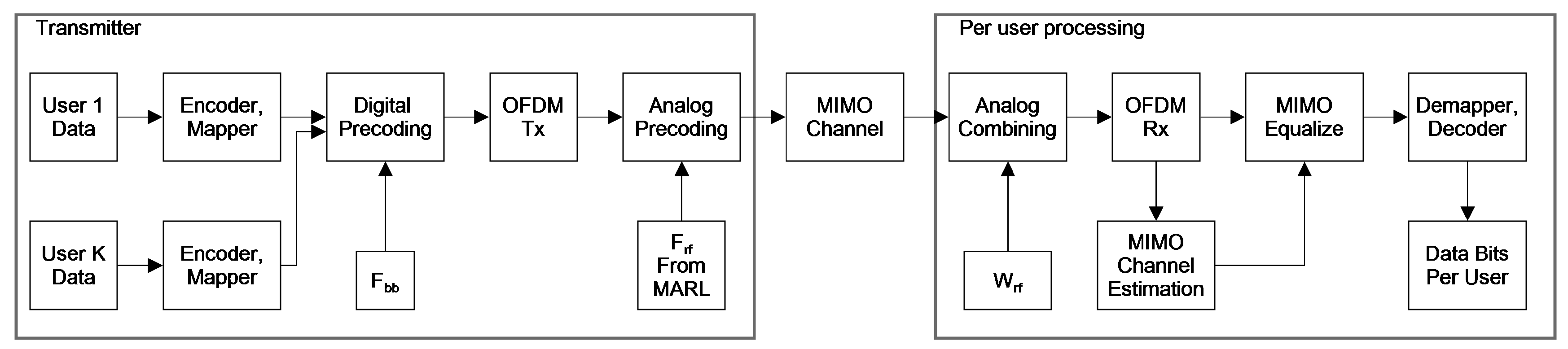
Figure 3.
Topographic map of ray tracing environment with one LOS and one nLOS user. Radiation patern for the 32 antenna BS is also shown forming beams toward each users.
Figure 3.
Topographic map of ray tracing environment with one LOS and one nLOS user. Radiation patern for the 32 antenna BS is also shown forming beams toward each users.
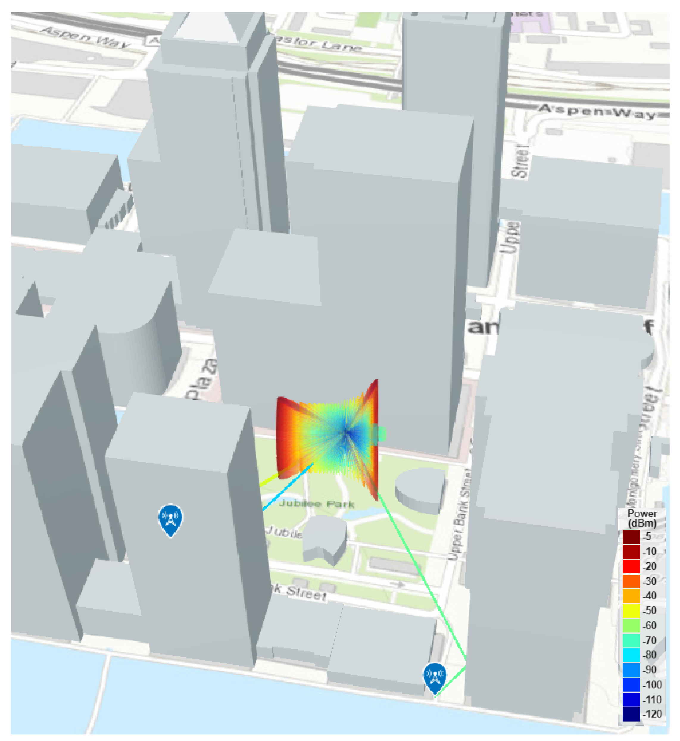
Figure 4.
SSB Beam Search in initial access procedure

Figure 5.
The proposed MARL system block diagram
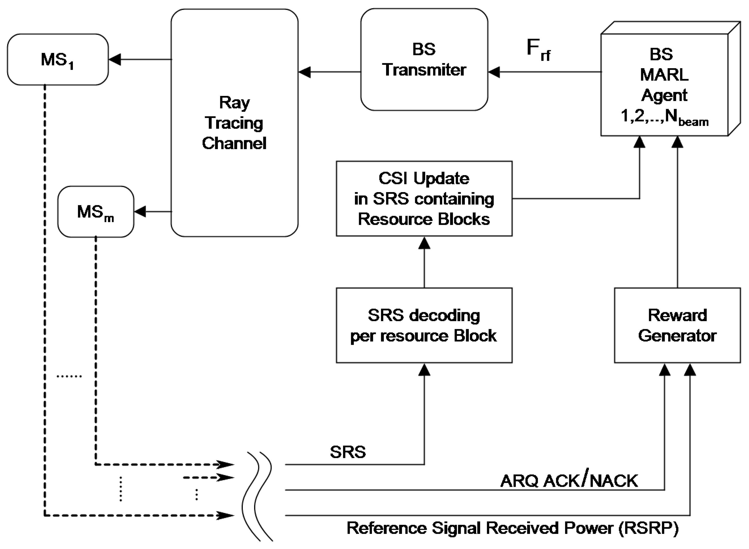
Figure 6.
Radiation Pattern for 32 element ULA antenna with number of phase shifter quantization bits (a)0 bits, (b)2 bits, (c)4 bits, (d)6 bits
Figure 6.
Radiation Pattern for 32 element ULA antenna with number of phase shifter quantization bits (a)0 bits, (b)2 bits, (c)4 bits, (d)6 bits
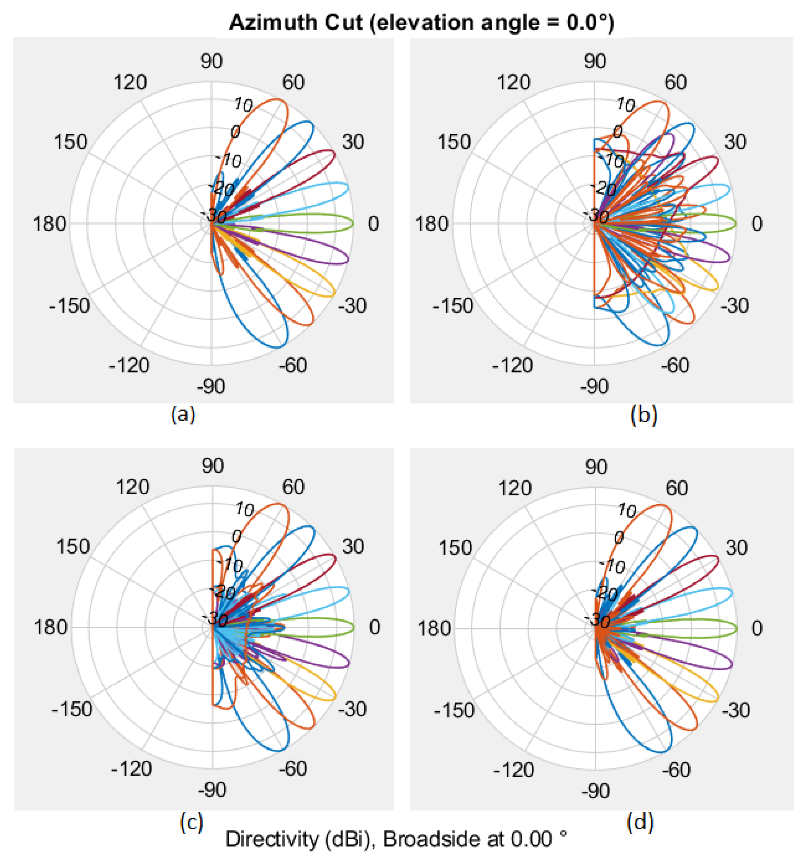
Figure 7.
Average beamforming gain comparison in LOS area
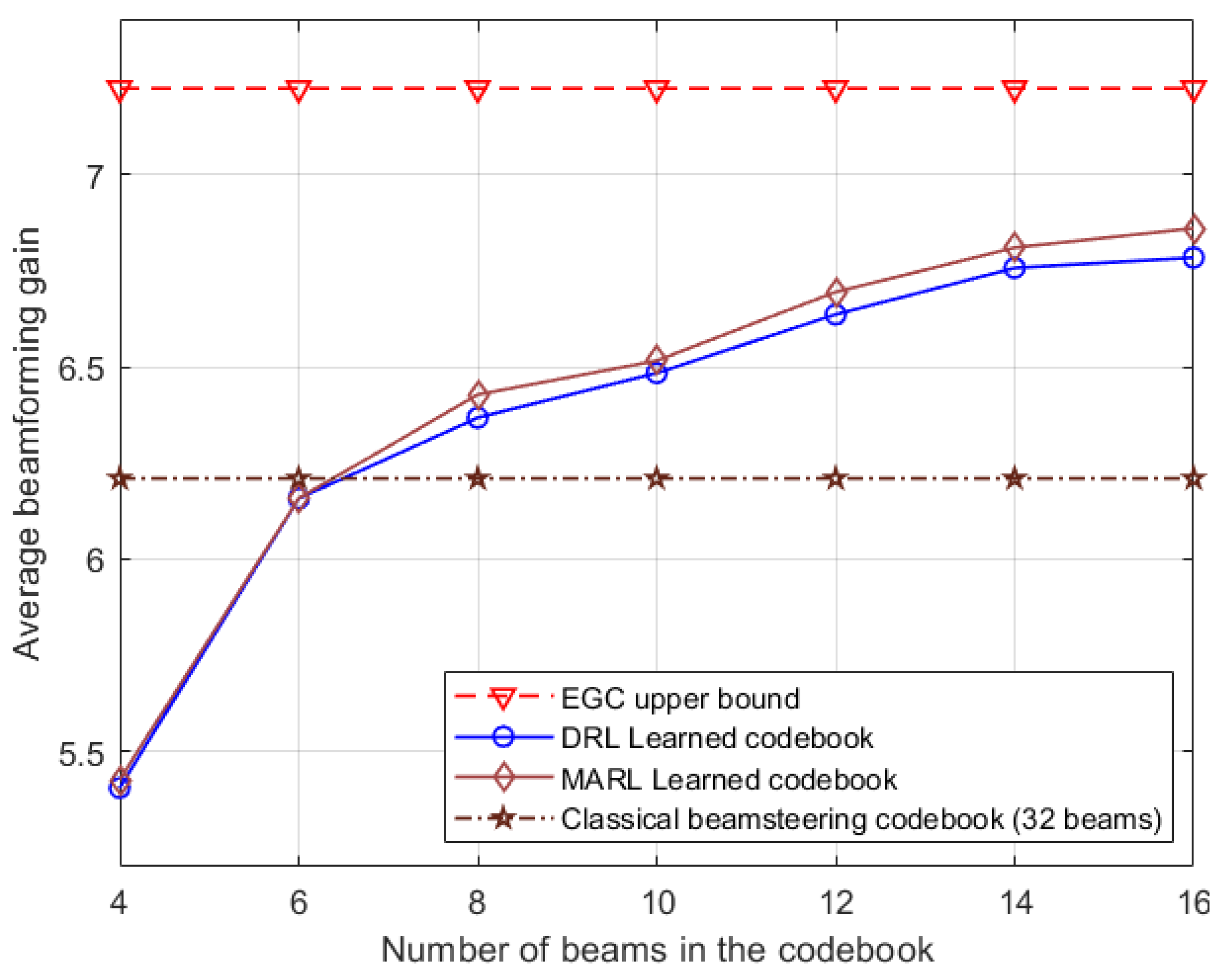
Figure 8.
Average beamforming gain comparison in nLOS BFgain nLOS area
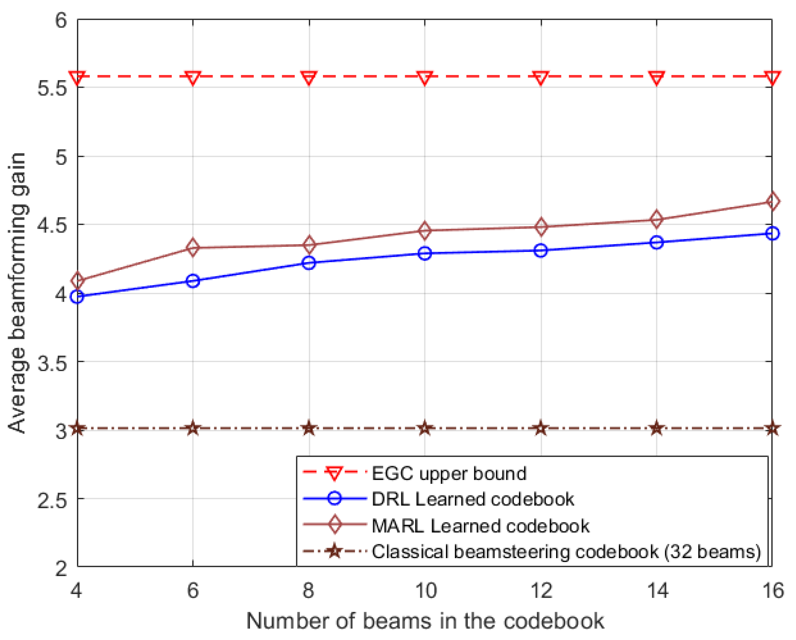
Figure 9.
SNR vs Sum Rate comparison


Table 1.
Transceiver parameter table.
| No. of user | 4 |
|---|---|
| Data streams per user | 1 |
| No. and type of base station antenna | 32, ULA, isotropic, back baffled |
| No. and type of receive antenna per user | 4, ULA, non back baffled |
| Modulation type | 16QAM |
| Frequency of operation | 28GHz |
| OFDM FFT length, CP length | 256, 64 |
| Encoder type, code rate (fixed) | Convolutional, |
Table 2.
Hyper parameter table for MARL.
| Optimizer | ADAM |
|---|---|
| Learning Rate | 0.01 |
| Target soft update parameter | 0.95 |
| Replay buffer size | 12,288 |
| Batch size | 1024 |
| No of samples added to replay buffer before each network update | 100 |
Table 3.
Comparison table for different attributes of studied methods.
| Perfect CSI not required | CSI Feedback not required | Antenna array response not required | Multiuser Interference avoidance in RF beams | DOA /DOD not required | Online training | Non iterative method | |
|---|---|---|---|---|---|---|---|
| MO [15] | × | × | × | × | × | × | |
| TS-HB [3] | × | × | × | × | × | × | |
| SOMP [16] | × | × | × | × | × | × | |
| CNN-MIMO [8] | × | × | × | ||||
| DRL [9] | × | ||||||
| MARL |
Disclaimer/Publisher’s Note: The statements, opinions and data contained in all publications are solely those of the individual author(s) and contributor(s) and not of MDPI and/or the editor(s). MDPI and/or the editor(s) disclaim responsibility for any injury to people or property resulting from any ideas, methods, instructions or products referred to in the content. |
© 2024 by the authors. Licensee MDPI, Basel, Switzerland. This article is an open access article distributed under the terms and conditions of the Creative Commons Attribution (CC BY) license (http://creativecommons.org/licenses/by/4.0/).
Copyright: This open access article is published under a Creative Commons CC BY 4.0 license, which permit the free download, distribution, and reuse, provided that the author and preprint are cited in any reuse.


