Submitted:
11 July 2024
Posted:
14 July 2024
You are already at the latest version
Abstract
Using numerical simulation method, combined with the pre-branch material characteristics of the measurement results, based on the LS-DYNA software to simulate the branch crushing process, the analysis found that not only the existence of the cutter cutting in the branch destruction process, there is also the cutting of the opposing surface of the bending fracture, with the increase in the speed of the knife rollers, the cutter cutting resistance increases, the cutting resistance reaches 2690 N when the cutter at 2500 r/min, the cutter cutting resistance is the smallest in the cutting simulation at the blade angle of 55°, the blade angle is more suitable for the cutting of the branch. In the cutting simulation under different cutting edge angles, the cutting resistance of the tool is the smallest when the edge angle is 55°, which is 1860 N. This edge angle is more suitable for branch crushing and cutting. Using Fluent software to analyse the airflow characteristics of the crushing device, it was found that with the increase of the knife roller speed, the inlet flow and negative pressure of the crushing chamber are increasing, the speed of 2500 r/min, the inlet flow and negative pressure were 1.92 kg/s and 37.16 Pa, which will be conducive to the feeding of branches, but the speed is too high and it will also lead to the enhancement of the vortex of part of the area in the crushing device, which will affect the feeding of branches and the throwing of the crushed material. affect the feeding of branches and the throwing out of crushed materials, and finally determined the speed range of the crushing knife roller is 1800 ~ 2220 r/min. Based on ANSYS/Model module modal analysis of the crushing knife roller, the knife roller of the first six orders of the intrinsic frequency and vibration pattern, crushing knife roller of the lowest order of the modal intrinsic frequency of 137.42 Hz, much larger than the crushing knife roller operating frequency of 37 Hz, the machine will not resonate during operation.
Keywords:
grapevine branches
; crushing collection
; simulation and test
1. Foreword
Through the simulation and test of grapevine branch crushing and collecting parts to determine the key structure of the machine and the range of working parameters, for the subsequent prototype of the field test to provide data reference. Firstly, LS-DYNA software was used to simulate and analyse the branch crushing process to investigate the effects of different knife roller speeds and knife edge angles on the branch crushing process. After that, Fluent software is used to simulate and analyse the characteristics of the airflow field in the crushing device to obtain the basic characteristics of the airflow field in the crushing device, and by analysing the characteristics of the flow field distribution under the conditions of different knife roller speeds, we investigate the effects of different knife roller speeds on the branch feeding, crushing and throwing performance, and finally determine the appropriate range of knife roller speeds. Finally, based on ANSYS/Model module, the modal analysis of the crushing knife roller is carried out to analyse the intrinsic frequency and vibration pattern of the knife roller, to investigate the relationship between the modal properties of the knife roller and the excitation frequency, and to determine whether there is resonance.
2. Simulation Analysis of Branch Crushing Process based on LS-DYNA
The process of branch crushing is a non-linear dynamic contact process between the tool and the grapevine branch, the deformation that occurs during the crushing process is quite complex, and the crushing process of the tool rotates at a high speed, it is difficult to study the role of the tool and the branch with each other by conventional methods, and finite element analysis provides a new method for the study of branch crushing. ANSYS/LS-DYNA is a display dynamics analysis software based on real-world physical problems. It is based on the Lagrangian algorithm and is often used as a display solver for solving highly nonlinear problems and transient dynamics problems[1,2].
When the machine is in operation, the branch will enter the crushing chamber after being plucked into the feeding inlet by the picking teeth, at this time, the knife will carry out preliminary cutting of the long branch that enters, and the cutting at this place is also the key to affect the qualified rate of the branch crushing, therefore, this section will carry out a simulation analysis of the crushing process of the branch in the feeding inlet in order to investigate the effect of different knife roller speeds and cutting edge angle of the knife on the process of the crushing of the branch.
2.1. Crush model Simplification and Establishment
The model of the crushing device for branch crushing is relatively complex, and it is not possible to set all the parameter conditions for the simulation using the model directly, so it is necessary to simplify the structure and keep the key parts so that the model can run properly in LS-DYNA and shorten the simulation time. The simplification steps of the model are as follows:
- A single grape branch was used in the simulation, ignoring the effects of branch curvature, cross-sectional shape changes, and branch nodes on the mechanical properties, and the branch was regarded as an elongated cylindrical model with a constant diameter and straightness, and the simplified branch model had a length of 220 mm and a diameter of 12 mm;
- The crushing device is simplified by reducing the hammer claw, the knife seat, the connecting parts and the knife shaft to a single knife roller entity, ignoring the head of the shaft, the bolted connecting parts, the tool reinforcement and the chamfer that does not come into contact with the branch, and shortening the crushing knife shaft to only one crushing tool;
- The crushing process does not consider branch-to-branch interactions, the branch is fed at a horizontal angle, and displacement constraints are applied to some regions of the branch, as shown in Error! Reference source not found. (b);
Figure 1.
Establishment of three-dimensional models of branches and knife rollers.
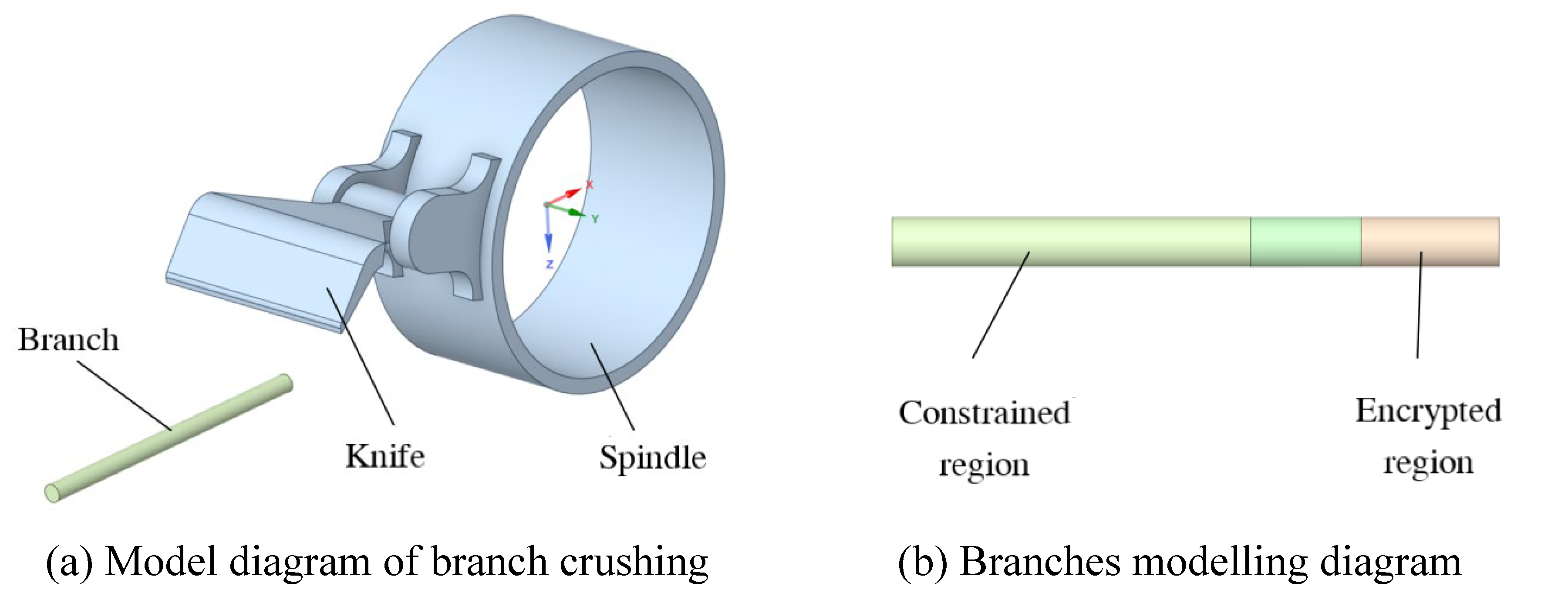
After determining the simplification scheme, SolidWorks software is used to model the model in three dimensions, and three kinds of crushing models are established with the cutting edge angles of 50°, 55° and 60°, named M-50, M-55 and M-60, respectively, and each model includes two entities of the branch and the knife roller, respectively, and the branch entity is partitioned, and the mesh encrypted area as well as constraint area are partitioned, and the model is saved in Parasolid (.x_t) format and imported into the pre-processing SpaceClaim software of ANSYS. Parasolid (.x_t) format, and imported into ANSYS pre-processing SpaceClaim software, the global coordinate system of the model is defined in the position of the axis of the knife axis, and then the shared topology operation is carried out on the split branch entities to ensure the transfer of the branch model data during simulation.
Since the centre of rotation of the rigid body in LS-DYNA software is the center of mass by default, and the actual centre of rotation of the tool roll is at the axis of the tool shaft, it is necessary to import the model with the defined global coordinate system into SolidWorks, and find the mass and inertia tensor of the tool roll with respect to the global coordinate system (Ixx,Iyy,Izz,Ixy,Iyz,Ixz), so as to define the rigid body properties to determine the center of rotation during simulation in LS-DYNA. Define the rigid body properties to determine the position of the centre of rotation for the simulation.
2.2. Crushing Model Material Definition and Meshing
(1) Definition of model materials
After loading the LS-DYNA module in ANSYS, click on the engineering data column to define the material properties of the knife roller and branch, in this paper, the knife roller is defined as a rigid body, with a material density of 7.85×10³ kg/m3, a modulus of elasticity of 210 GPa and a Poisson's ratio of 0.3; According to the mechanical properties of the branch and the simplification requirements of the model in the previous stage, an isotropic elastic-plastic material model is selected for the branch material *MAT_PLASTICK_INEMATIC[3].Combined with the relevant literature, the model material parameters are defined as shown in Error! Reference source not found.

Table 1.
Material parameters of branch model.
| Character radical | Densities/kg·m-3 | Modulus of elasticity/MPa | Poisson's ratio | Yield stress/ MPa |
Tangent modulus/MPa | Strain Rate/C |
Strain Rate/P |
Effective plastic strain |
| Branches | 881.49 | 498.51 | 0.4 | 16.6 | 0.7 | 100 | 10 | 0.07 |
(2) Model meshing
Mesh partitioning is an important part of the LS-DYNA simulation process, which determines the speed of simulation calculation as well as the solution accuracy. For the meshing of the crushing model, if the cell size is too large, it will be difficult to respond to the detailed process when the branch is damaged, but if the cell size is too small, the huge number of cells in the model will greatly increase the computation and the simulation cost[4,5],so the present model adopts the method of encrypting the local contact area for meshing.
All the geometry in the model is meshed using a tetrahedral meshing method and the algorithm is the patch conformal method, after which the regions are resized: branches encrypted area for face size meshing, cell size of 1 mm; branches encrypted area outside the part of the geometry of the cell size adjustment of 2 mm; knife roller geometry as a whole cell size size adjustment of 10 mm; the tip of the knife part of the edge of the size adjustment of 1 mm; knife edge chamfering arc face face size adjustment of 1 mm cell size. For three different tool edge angle of the crushing model using the above method were mesh division, model M-50 division results are shown in Error! Reference source not found., the use of skewness evaluation criteria to assess the quality of model mesh division, M-50, M-55, M-60 three models mesh division and quality assessment results are shown in , the average value of the skewness are less than 0.5, the quality of the better.
Figure 2.
Mesh division of branches and knife rollers.
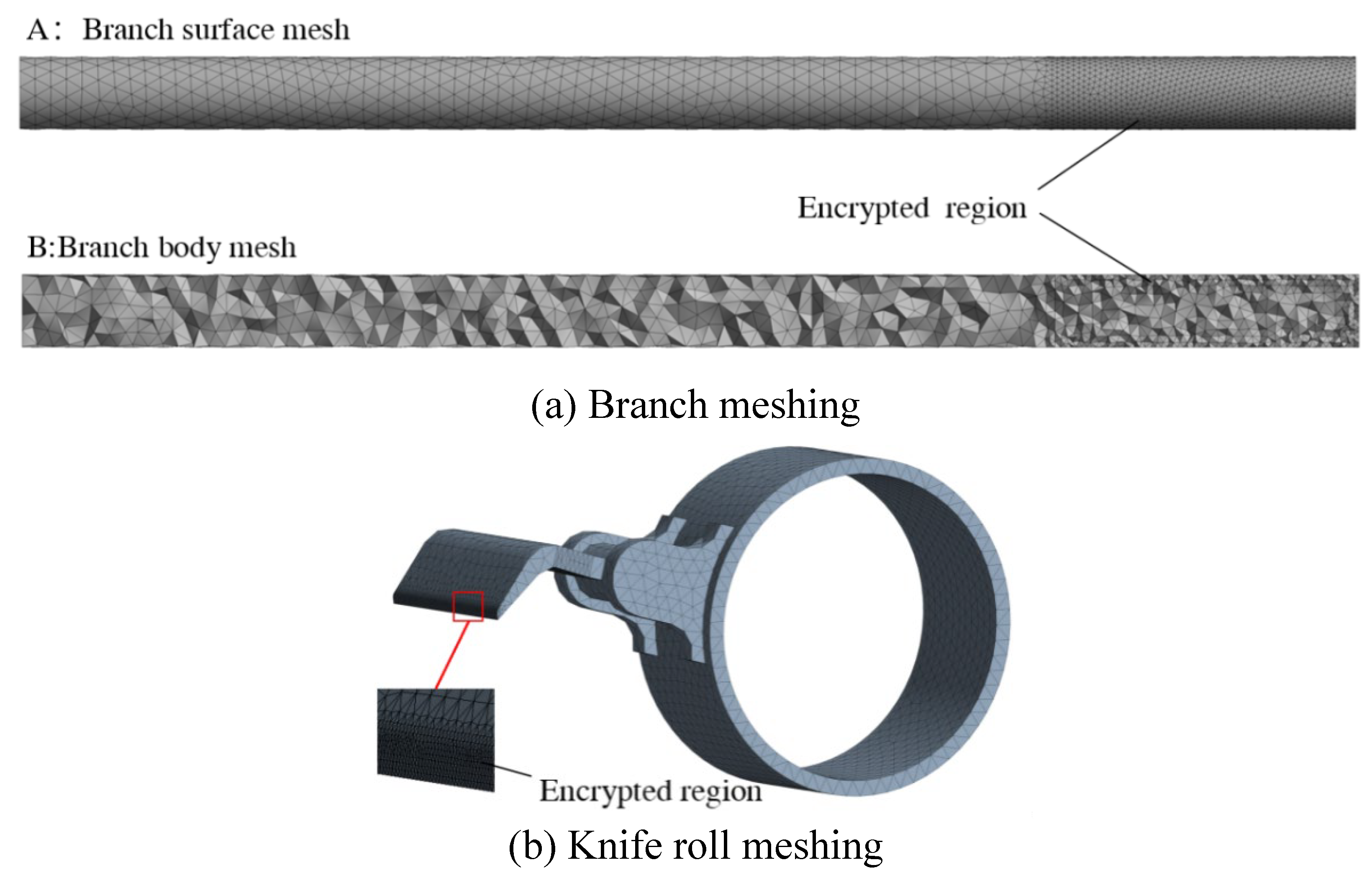
Table 2.
Model grid division and quality evaluation results.
| Crushing Models | Number of units | Number of nodes | Skewness | ||
| Minimum value | Maximum values | Average value | |||
| M-50 | 50078 | 12213 | 2.681×10⁻⁵ | 0.894 | 0.257 |
| M-55 | 52084 | 12624 | 8.165×10⁻⁷ | 0.889 | 0.254 |
| M-60 | 48843 | 11985 | 2.725×10⁻⁵ | 0.893 | 0.256 |
2.3. Defining Contact Types, Constraints and Analysis Settings
(1) Define contact type
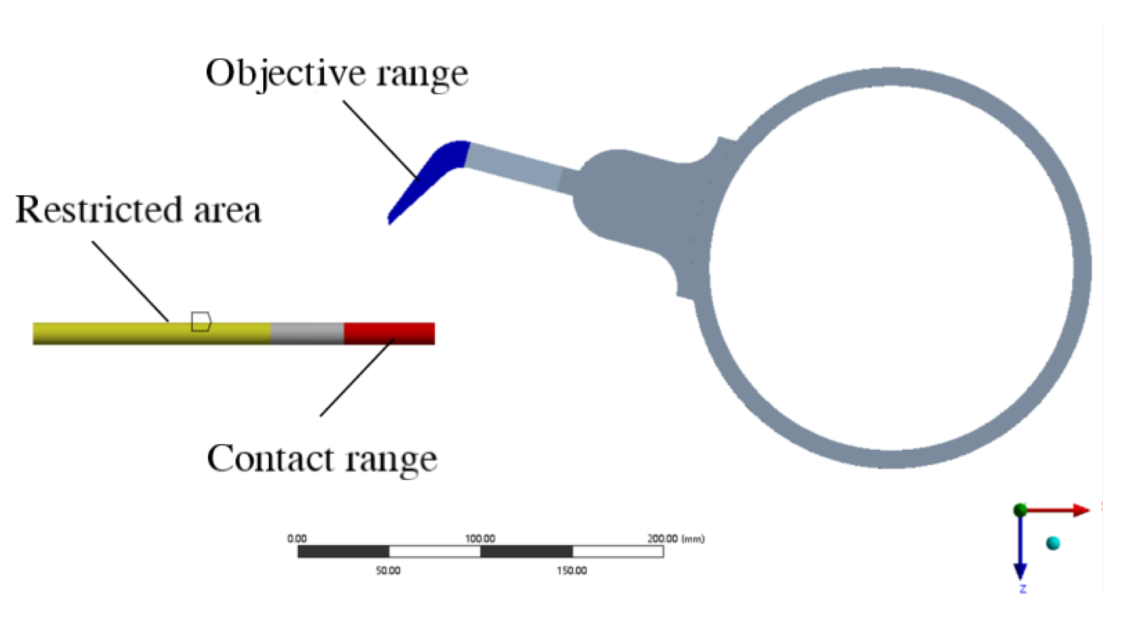
The contact in the crushing model is mainly the contact between the end of the crushing tool and the branch, when crushing, the end of the tool is not only in contact with the surface of the branch, but also invades into the branch geometry to generate contact, insert the "Contact Area" object into the "Connection" in the LS-DYNA interface. Insert the "Contact Area" object into the "Connection" in the LS-DYNA interface, specify the target area as the surface of the end of the tool (including 6 surfaces), and the contact area as the encrypted area of the branch model, as shown in Error! Reference source not found., and define the contact type as "Friction". The coefficient of static friction between the tool and the branch is set to 0.39, and the coefficient of kinetic friction is set to 0.12. At the same time, we inserted the "Contact Characteristics" into the solver and defined the type as "Erosion".
Figure 3.
Initial interface of crushing process.
(2) Defining constraints
The constraints in the crushing model include the constraints of the branch and the constraints of the knife roller. The displacement constraints are defined for the branch in the solver, with the x and y components set to free and the z component set to 0 displacement. Since the knife roller attribute is rigid body, the knife roller rotates around the axis in the crushing process, so the rigid body constraint is added to the knife roller, which is set to rotate freely around the y-axis, and the remaining five degrees of freedom are set to be fixed; the centre of rotation of the knife roller is the centre of mass of the rigid body in LS-DYNA by default, so it is necessary to define the attribute of the rigid body in the solver in order to ensure that it rotates around the axis of the knife axis, and the mass and inertia tensor of the knife roller is inputted into the solver according to the pre-solved mass and inertia tensor of the knife roller in relation to the global coordinate system. mass and inertia tensor, input the inertia parameters, and define the coordinates of the rotation centre (x,y,z) as the position of the origin of the global coordinate system.
(3) Analytical settings
Since the present study is to explore the comminution problem at different speeds, the comminution knife roller speeds were set to 1.7×10³ r/min, 2.1×10³ r/min, and 2.5×10³ r/min, respectively. If the force constraint is not applied to the knife roller rigid body in the simulation process, and only its initial rotational speed is set, some of its kinetic energy will be converted into internal energy and the kinetic energy of the branch when the rigid body is in contact with the branch, which leads to the decrease of the rotational speed of the rigid body in the crushing process, and it is not possible to ensure that the rigid body rotates at a uniform speed, and the actual force of the rigid body is more complicated, so it is necessary to apply a forced node rotation associated with the time to the rigid body.
Define the end time as the rotation time of the rigid body in the analysis settings, insert "Rigid Body Rotation" into the solver and define its rotation size around the y-axis as "Table Data", enter the linear data of rotation angle and rotation time in "Table Data", and define the initial time and initial angle under the conditions of 1.7×10³ r/min, 2.1×10³ r/min and 2.5×10³ r/min for the three rotational speeds of knife roller. In the "table data", enter the linear data of rotation angle and rotation time, and under the conditions of three rotational speeds of 1700 r/min, 2100 r/min and 2500 r/min of the knife roller, define the initial time and initial angle as 0, and the end time and angle as 3×10⁻³ s rotation of 30.6°, 2.38×10⁻³ s rotation of 30°, 2×10⁻³ s rotation of 30°, and 2×10⁻³ s rotation of 30°, respectively. 10-3 s rotation 30°. Finally, 100 equidistant points were set in the output control of the analysis setup, and the equivalent force, overall hourglass energy, kinetic energy and internal energy were added in the "solution" in order to analyse and study the whole crushing process.
2.4. Simulation Results and Analysis
The simulation study of the branch crushing process, were carried out under the conditions of different knife roller speed and different tool edge angle simulation comparison, a total of five simulation simulation, and five simulation of the overall hourglass energy to total energy ratio are less than 5%, indicating that the model numerical fit is reasonable and the simulation results are reliable[6,7]. Error! Reference source not found. gives the branch cutting process under the parameter conditions of knife axis speed of 1700 r/min and tool edge angle of 55°. It can be seen that the cutting process of the tool includes four positions of start cutting, start cutting, deep cutting and cutting completion, of which the deep cutting also includes the position of the maximum stress position and the lower part of the disconnection position, as shown in Error! Reference source not found. (a) to Error! Reference source not found. (f).
Figure 4.
The process of crushing grape branches.
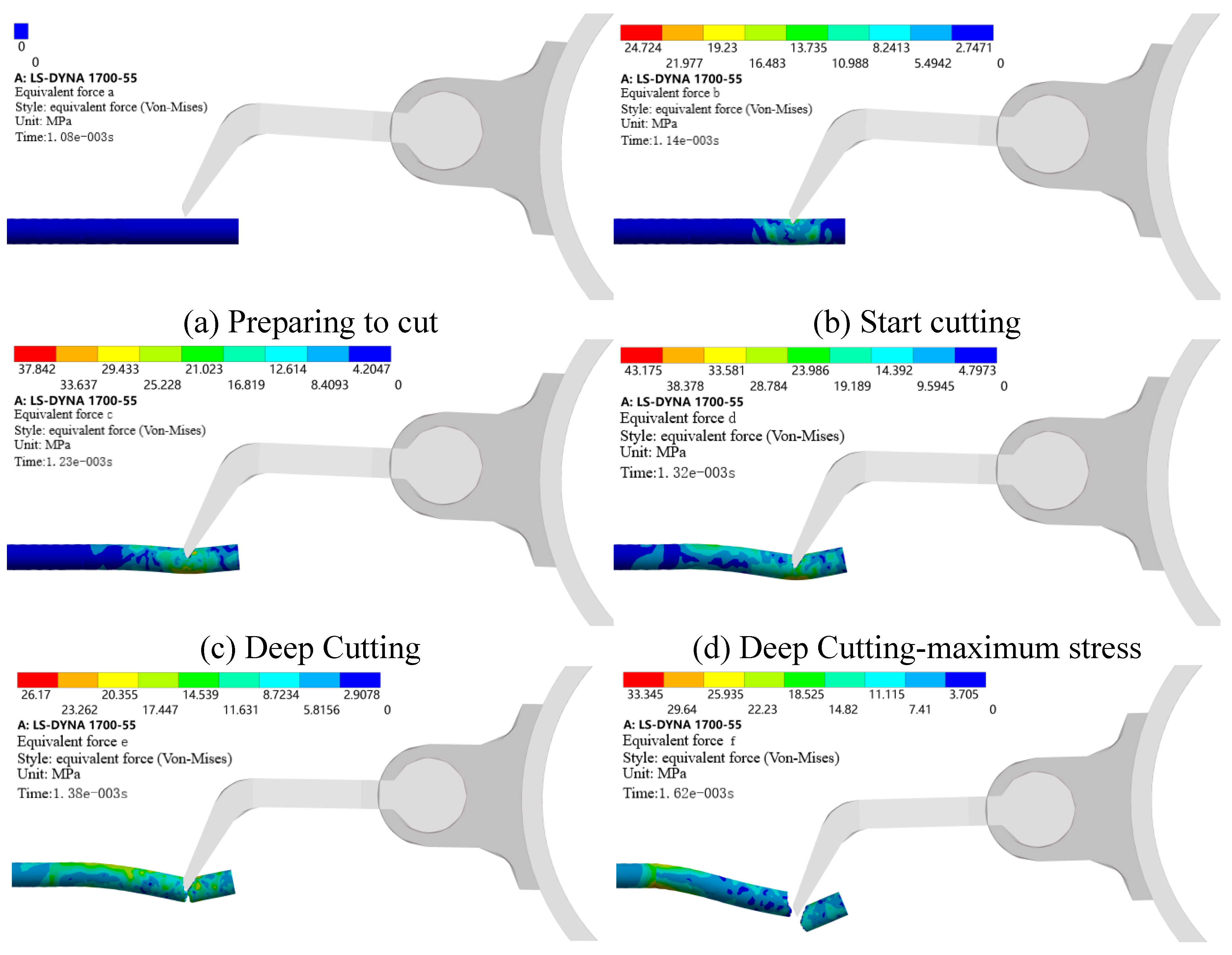
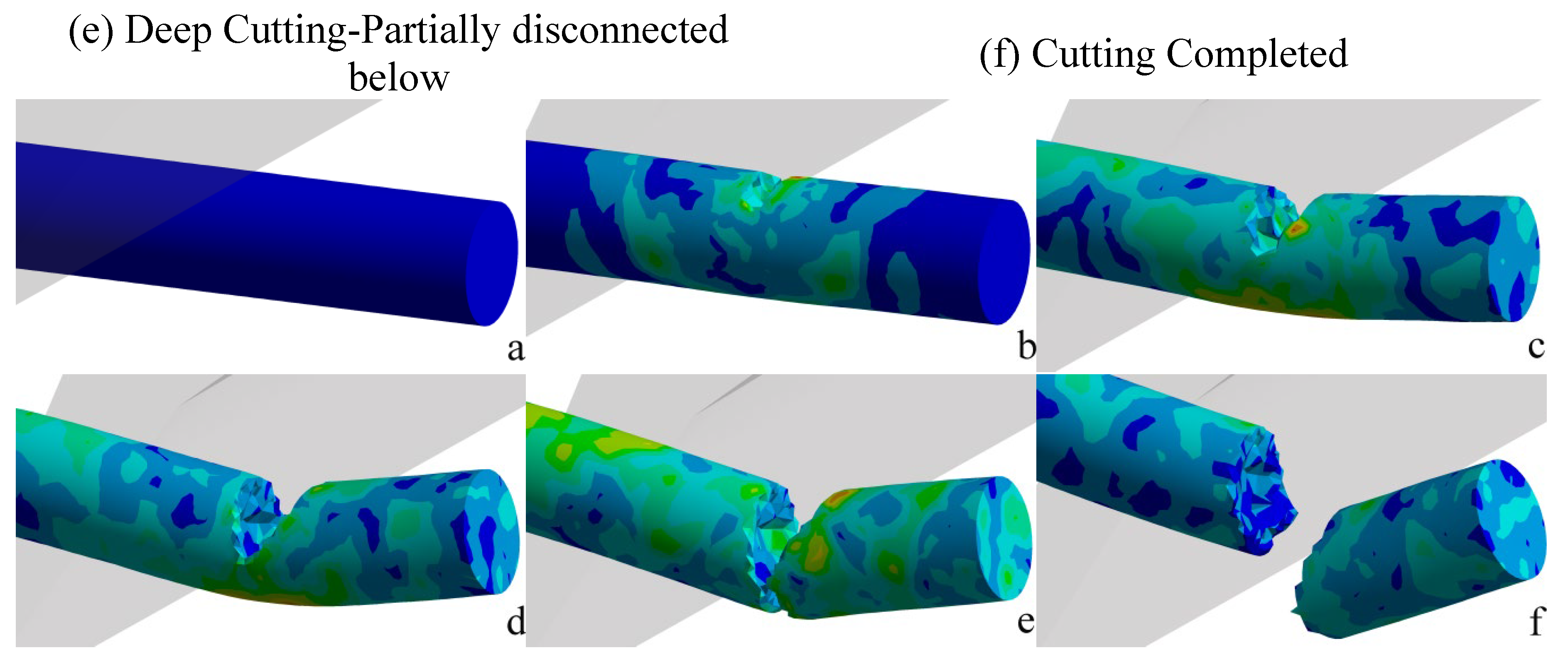
At the starting moment Error! Reference source not found. (a), when the tool is about to make contact with the branch, the equivalent force is zero; Initial contact between the branch and the tool occurs at 1.14×10⁻³ s. Due to the high rotational speed of the tool, the branch is subjected to a large impact and the load changes abruptly, at which time the maximum equivalent force reaches 24.724 MPa; Error! Reference source not found. (d) shows the branch cutting state when the maximum equivalent force of the whole crushing process occurs, the time of occurrence is 1.32×10⁻³ s, the branch produces a large deformation, at this time the size of the equivalent force is 43.175 MPa; At 1.38×10⁻³ s the branch breaks off from the cut opposite side, as shown in Error! Reference source not found. (e); The branch finished cutting at 1.62×10⁻³ s. As shown in Error! Reference source not found. (f), the uneven cut section of the branch can be fully observed, and at this time, the branch is still in the bending state, and there exists internal stress, with the maximum value of equivalent stress of 33.345 MPa. From the whole cutting process, it can be seen that the destruction process of the branch not only exists in the tool cutting, but also in the bending and breaking of the opposite side of the cutting place, so that the branch crushed will present an irregular cutting section.
(1) Simulation analysis of the crushing process at different knife roller speeds
Crushing process, crushing knife roller speed is a key factor affecting the cutting force, the simulation analysis of the knife edge angle of 55°, knife roller speed were 1.7×10³ r/min, 2.1×10³ r/min, 2.5×10³ r/min, the use of LS-DYNA simulation analysis, the use of post-processing software LS-Prepost to open the generated d3plot * as well as the rcforce* files, to produce the cutting force - time curve in the branch crushing process, to facilitate the cutting process of the cutting force in all directions and the cutting force analysis. The generated cutting force-time curves are shown in Error! Reference source not found. (a) ~ (c), where time (Time) is in s, contact force (Rcforce Data) is in N, and the horizontal coordinate time range is taken as the effective cutting period of the branch.
Figure 5.
Cutting force time curve under different blade roller speeds.
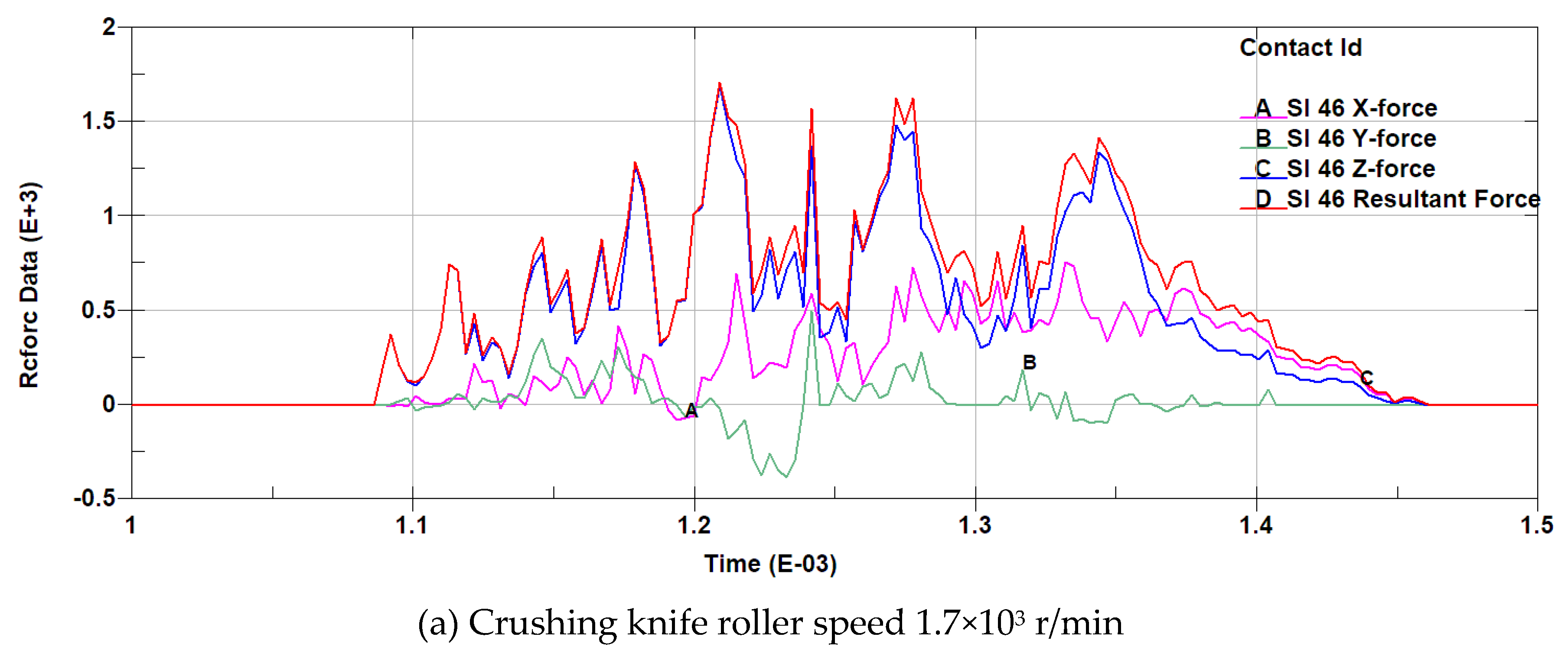
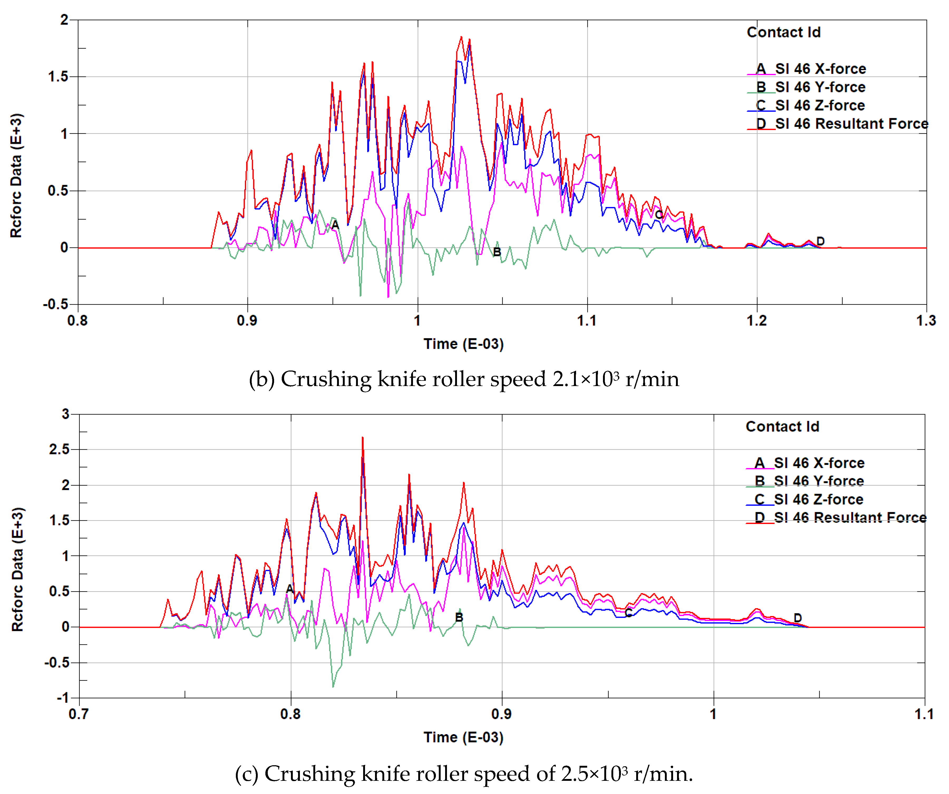
Analysis of Error! Reference source not found. (a) ~ (c) shows that under the three rotational speeds of 1.7×10³ r/min, 2.1×10³ r/min and 2.5×10³ r/min, the cutting force of the knife has been oscillating with time, which is due to the fact that in the simulation process, the unit within the branch model is damaged after the strain generated exceeds its permissible strain as the knife cuts deeper, and part of the force will be unloaded. Further analysis shows that the simulation process of three different knife roller speed, with the increase in rotational speed of the branch cutting process will be completed in a shorter period of time, the cutting process in the Y-direction cutting force is smaller, the maximum value of the Z-direction cutting force is the largest, and the maximum value of the cutting force in the X, Z direction are with the increase of rotational speed increasing, from small to large three speed of the cutting force (the value of the reaction on the tool for the resistance to cutting) The maximum values are 1.71×10³ N, 1.86×10³ N, 2.69×10³ N, corresponding to the time of 1.21×10⁻³ s, 1.03×10⁻³ s, 8.34×10⁻⁴ s, respectively, as shown in Error! Reference source not found., it can be seen that the maximum value of the cutting resistance is also increased with the increase in the rotational speed of the knife roller, and the maximum value of the time of occurrence is also in advance. Through the above analysis, it can be seen that in the crushing process to increase the knife speed although it will enhance the crushing efficiency, but the knife cutting resistance is also increasing, so in order to meet the conditions of branch cutting should be selected in the low range of the knife roller speed.
Figure 6.
Maximum cutting resistance and corresponding time at different blade roller speeds.

(2) Simulation analysis of comminution process under different tool edge angles
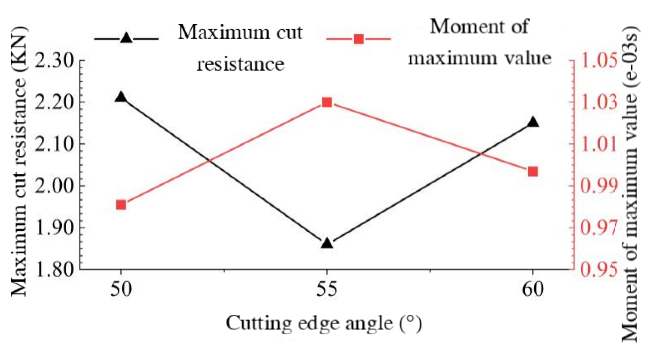
Error! Reference source not found. (a), Error! Reference source not found. (b) and Error! Reference source not found. (b) reflect the cutting force-time curves at the knife roller speed of 2100 r/min and the tool edge angles of 50°, 55° and 60° respectively. It can be analysed that the effective cutting time decreases accordingly with the increase of the tool edge angle and the cutting force is smaller in the Y direction during the cutting process and the cutting force is the largest in the Z direction, and the maximum cutting force is the smallest in the X and Z directions at the edge angle of 55°. When the cutting angle is 55°, the maximum cutting force in X and Z direction is the smallest. The maximum value of the combined cutting force of the tool with 50°, 55° and 60° cutting edge angle is 2.21×10³ N, 1.86×10³ N and 2.15×10³ N, respectively, and the corresponding time is 9.81×10⁻⁴ s, 1.03×10⁻³ s and 9.97×10⁻⁴ s, respectively, which is shown in Error! Reference source not found., and it can be seen that the maximum value of the combined cutting force is the smallest when the cutting edge angle is 55°. Therefore, under a certain rotational speed, the cutting resistance is the smallest when the cutting edge angle of the tool is 55°, which is more suitable for crushing and cutting of grapevine branches.
Figure 7.
Cutting force time curve under different cutting tool angles.
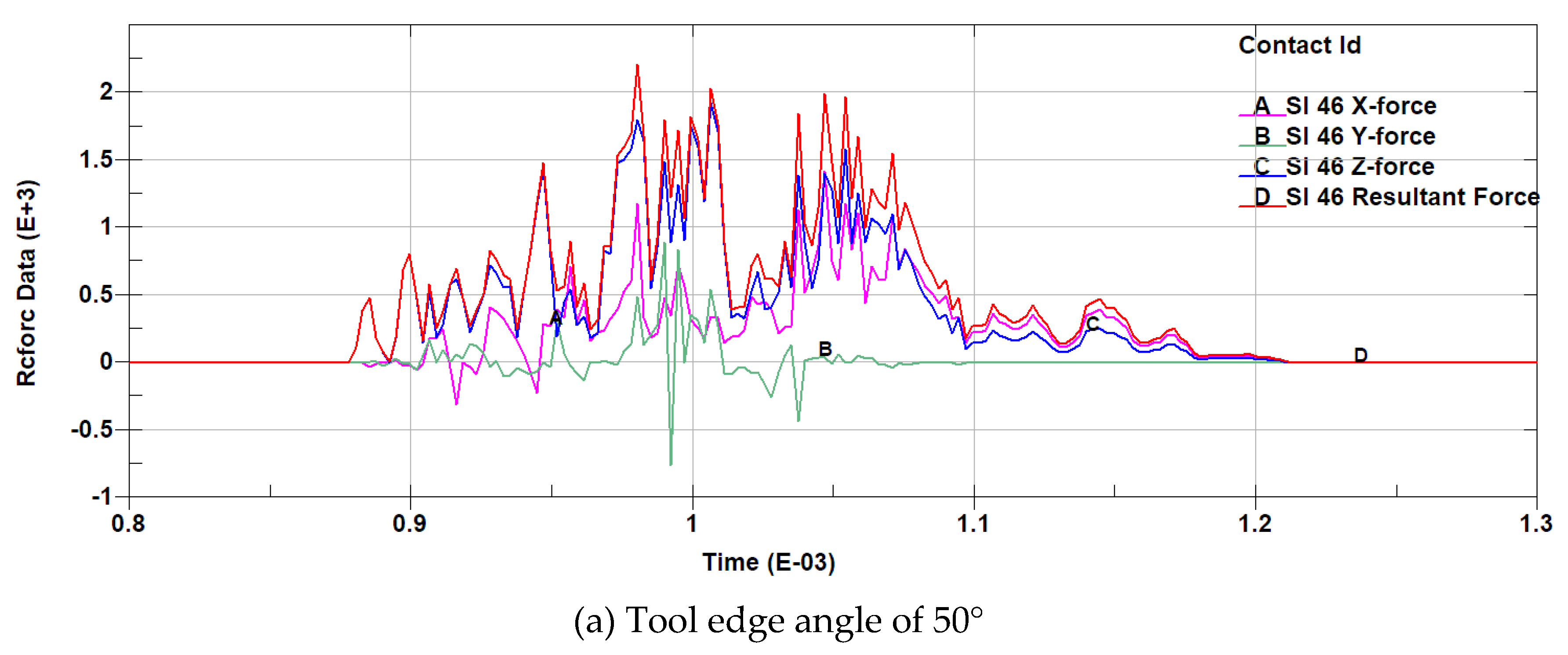
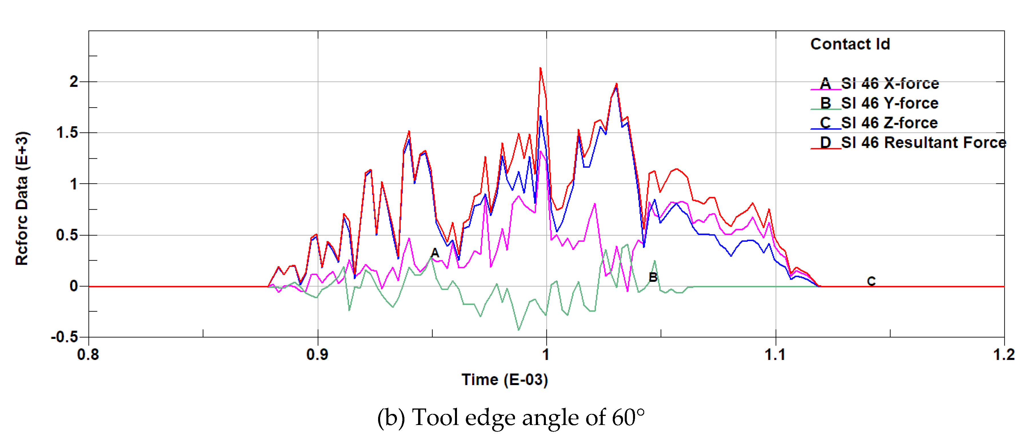
Figure 8.
Maximum cutting resistance and corresponding time under different cutting tool angles.
3. CFD-Based Simulation Analysis of the Flow Field Characteristics in the Crushing Device
When the branch crushing and collecting machine is in operation, the characteristics of the airflow field in the crushing device affect the feeding of branches, the quality of crushing and the throwing of crushed materials, especially the high-speed rotation of the crushing knife rollers will make the crushing device form a complex flow field. This chapter will establish a simplified model of the crushing device of the branch crushing and collecting machine, based on the CFD numerical simulation method, using Fluent software, simulation and analysis of the characteristics of the airflow field in the crushing device, to obtain the basic characteristics of the flow field in the crushing device, and to compare and analyse the distribution characteristics of the flow field under the conditions of different speed of the crushing knife rollers in order to explore the influence of the speed of rotation on the branch feeding, crushing and transporting, and provide a reference for the subsequent field test of the prototype. This is to investigate the effect of rotational speed on branch feeding, crushing and throwing, and to provide a reference for the subsequent field test of the prototype.
3.1. Crushing Device Model Building and Meshing
Crushing device model establishment and simplification is the basis for subsequent CFD simulation, simulation before the simulation, the first use of SolidWorks software to establish the crushing knife roller, rotating area and crushing the three-dimensional model of the cavity, and in the process of modelling some of the structure of the simplified processing: Neglect part of the chamfer of the hammer claw and the reinforcement; remove the bottom ends of the tool holder; ignore the connecting bolts and nuts, and consider the hammer claw and the tool holder and the tool shaft as a whole; ignore the shaft head at both ends of the tool shaft, and simplify the tool shaft to a through straight cylinder, so as to subsequently extract the domain of the fluid calculation. The established model file is saved as Parasolid (.x_t) format, imported into ANSYS pre-processing software SpaceClaim Boolean operation, extract the rotational domain and static domain, and then the entire computational domain for the shared topology operation to ensure that the rotational domain and the static domain of the data transfer between the group for the model to create "NS In the group, create "NS" for the model, select and name the inlet, outlet and wall of the computational domain, and the processed 3D model is shown in Error! Reference source not found. (a).
Figure 9.
3D model and grid division diagram of crushing device.

After the model processing is completed, run ANSYS-Workbench and load Fluent (with Fluent Meshing) components, enter the Fluent meshing interface and select "Watertight Geometry" for meshing, import the fluid calculation domain. model, mesh encryption on the wall of the crushing knife roller, and then generate the computational domain surface mesh. The geometric model is set to consist of a fluid domain with no voids, and the fluid-fluid boundary is changed from "wall" to "interior" to determine the boundary of the computational domain:The inlet and outlet are set to Pressure-inlet, Pressure-outlet respectively, and all areas of the model are set to Fluid. Adds a boundary layer to the computational domain model walls with an offset method type of Smooth-transition and other parameters as default. The Ploy-Hexcore method is applied to the computational domain for body meshing, which is well adapted to surfaces and produces a small number of meshes[8,9], resulting in a total of 1.49×10⁶ solid cells and 4.32×10⁶ mesh nodes. Automatic node movement is performed on the cell area to improve the grid quality, and finally the grid quality is evaluated by applying the skewness evaluation criterion, and the average value of skewness is 0.066, the maximum value is 0.536, and the grid classification grade is "Excellent".
3.2. Model Simulation Parameter Settings
(1) Fluid flow control equations and turbulence model selection
Branch crushing throwing process, branches in the crushing chamber after crushing through the discharge pipe thrown, in which the crushed material is transported in the hammer claw and crushing device under the joint action of the airflow to complete the crushing device in the form of air movement is actually gas - solid two-phase turbulent movement, but the direct analysis is difficult, and the use of Fluent simulation software to analyse the crushing chamber of the gas-phase flow can be indirectly obtained by crushing material Motion form[10], simulation and analysis process ignoring the air and the energy transfer between the crushed material, crushing device within the gas-phase flow follow the law of conservation of mass and momentum conservation. Mass conservation equation is:
In the equation: div is the dispersion, ρ is the fluid density, and u、v and w are the velocity vectors in the x、y and z directions.
The momentum conservation equation is:
In the equation: Pw is the pressure on the microproducts, t is the time, and ,SU、SV、SW are generalised source terms.
The high-speed rotation of the knife roller in the crushing chamber will make the flow field in the crushing device to produce vortex phenomenon, so in the flow simulation process need to choose the appropriate computational model, in order to obtain and the actual crushing chamber air flow characteristics of the similar results. The flow field in the crushing chamber in this study is dominated by turbulence, so a turbulence model is chosen for the simulation. The k-ℇ turbulence model in Fluent is computationally stable and efficient and is widely used in turbulence simulation[11,12],The k-models include Standard k-ℇ, RNG k-ℇ and Realizable k-ℇ models, among which Realizable k-ℇ models are more commonly used and can better solve turbulent flow problems[13]. Therefore, the Realizable k-ℇ model is chosen in this simulation to simulate the airflow field in the crushing chamber, and the transport equations for k and ℇ are given in Equation (5) and Equation (6).
In the equation: C1=max[0.43,η/(η+5)], C2=1.0, Uj is the fluid velocity, k is the turbulent kinetic energy, μt is the effective viscosity, ℇ is the turbulent dissipation rate, xj is the component of x in the j-direction, St is the generating term of turbulent kinetic energy, σk is the Prandtl constant related to the turbulent kinetic energy taken as 1, σ is the Prandtl constant related to the turbulent dissipation rate taken as 0.7179, η is the strain rate, C1, C2 is the constant coefficient on the turbulence dissipation, C1 taken as 1.42, C2 taken as 1.68[14].
When using Fluent software to simulate and analyse the airflow field inside the crushing chamber, the Navier-Stokes control equation used to solve the airflow field is:
In the equation:va is the gas-phase fluid velocity vector, and Fci represents the momentum sink. Referring to the relevant literature, it can be seen that the turbulent velocity and pressure of pumps, fans and other systems are basically constant and time-independent, which is called the time-averaged value when the system works stably. The turbulence can be expressed by the time-averaged motion parameters called time-averaged turbulence, and the turbulence can be regarded as constant flow, at this time the continuity equation, kinetic energy equation and Bernoulli's equation can be applied to the time-averaged turbulence[15].
(2) Parameter setting
After the mesh division is finished, the simulation operation condition is set to double precision in Fluent, and after entering the solution interface, the mesh is checked firstly to make sure that there is no negative volume and then continue with the parameter setting. In the simulation, the flow field is regarded as incompressible, the fluid medium is set as air, and the steady state, pressure-based solver is selected. The working conditions of the computational domain are set, the gravitational acceleration is 9.8 m/s2 in the negative direction of the Z-axis, and the operating pressure is 1.01×10⁵ Pa (one standard atmospheric pressure). The rotational domain is defined using the multiple reference system model (MRF):According to the demand of this simulation analysis, the knife roller speed is set to 1.7×10³ r/min, 2.1×10³ r/min and 2.5×10³ r/min respectively; define the rotation threshold to rotate around the centre axis, i.e., the Y-axis, in the positive direction. The inlet and outlet of the computational domain are set as pressure inlet and pressure outlet respectively, and the gauge pressure at the inlet and outlet are set to 0 Pa. The solution method is the pressure-velocity coupling algorithm for steady state computation. The solution method is the pressure-velocity coupling algorithm for steady state computation, and the scheme is Simple, the pressure interpolation algorithm is PRESTO algorithm which is suitable for high Xuan-flow and the pressure changes rapidly in the fluid domain[16,17,18], and the momentum, turbulent kinetic energy and dissipation rate are all in the Second Order Upwind format which has a high computational accuracy[19], and the Warped-Face gradient correction is chosen, and the sub-looseness factor is the default value. The subrelaxation factors are all default values. After initialisation of the mix, set the number of operation iterations to 2000, after which the calculation starts until convergence. After convergence, the entry and exit mass flow reports are viewed and the difference between the entry and exit flows is calculated to be less than 0.5% to ensure that the simulation results are valid.
3.3. Model Simulation Results and Analysis
After the end of the flow field simulation operation, the results will be imported into the CFD-Post software for post-processing of the simulation results, in order to more intuitive description of the flow field distribution characteristics of the crushing device, the establishment of seven representative two-dimensional cross-section in the computational domain, the location of the cross-section as shown in Error! Reference source not found..
Figure 10.
Cross section location map of fluid computing domain.
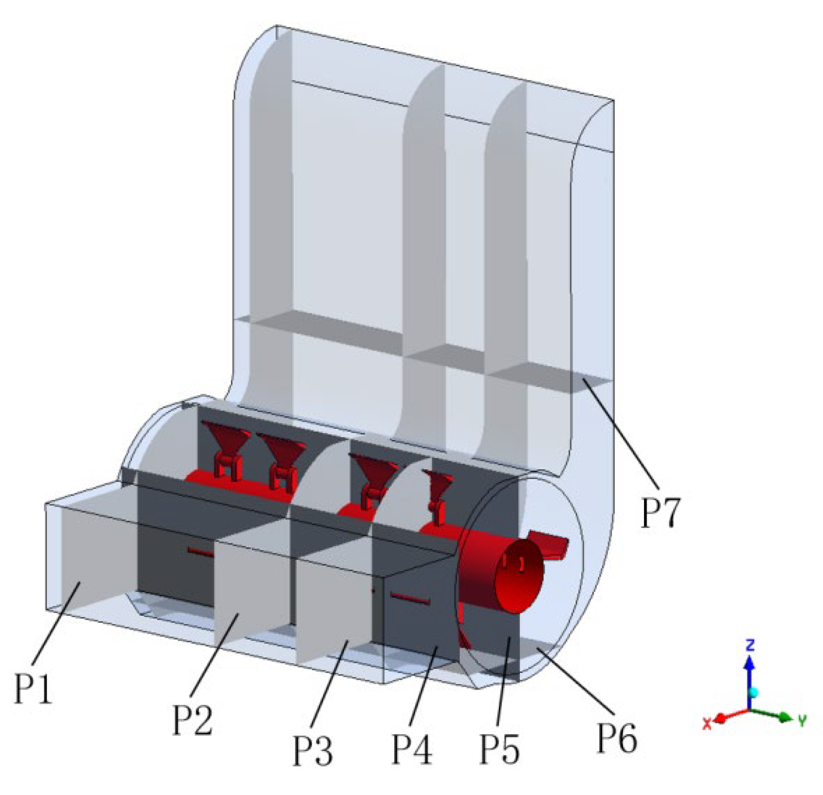
The P1 cross-section is at the left boundary of the computational domain, parallel to the XZ plane and Y=-580 mm; the P2 cross-section is a symmetric plane at the centre of the computational domain; the P3 cross-section is in the right region of the fluid domain, parallel to the XZ plane and Y=310 mm; the P4 cross-section is close to the inlet region and passes through the end of the hammer claw, parallel to the YZ plane and X=271 mm; the P5 cross-section is overlapped with the YZ plane and passes through the axial line of the knife roller P6 is located at the bottom of the calculation domain, parallel to the XY plane, Z=-250 mm; P7 is located in the middle and lower part of the discharge pipe, parallel to the XY plane, Z=500 mm.
(1) Crushing indoor velocity field analysis
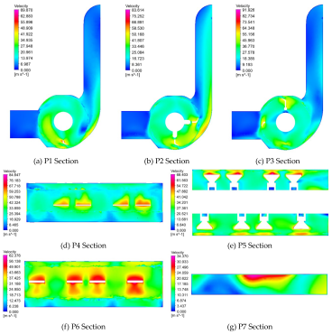
In this section, the velocity field inside the crushing device is analysed at a knife roller speed of 2.1×10³ r/min, and the velocity cloud of the P1 ~ P7 cross-section is shown in Error! Reference source not found.. From the P1 ~ P3 and P5 cross-section velocity cloud diagrams, it can be seen that the airflow velocity in the inlet area is lower, and the flow velocity at the bottom area of the inlet is higher; the mean values of the P1 ~ P3 cross-section velocities are 21.383 m/s-2, 27.553 m/s-2, and 28.063 m/s-2, which can be seen that the average velocity in the computational domain located in the boundary is lower, and the average velocity located in the centre area is higher and the change is not It can be seen that the average velocity in the calculation domain is lower at the boundary, and the average velocity in the centre area is higher and does not change much; the air velocity in the rotating area of the knife roller is higher, the air velocity in the rotating area is increasing along the radial direction of the knife roller and the air velocity decreases from the rotating area into the discharge pipe. From P4 and P6 cross-section can be seen in the tool leeward area of the airflow velocity is higher than the windward area, from P1 ~ P3, P7 cross-section velocity cloud can be seen, the discharge pipe near the right side of the crushing device is higher than the speed of the left side of the region near the speed, and the central region of the highest speed, which is consistent with the theoretical design of crushing device. The high-speed rotation of the knife roller will also be in the knife roller rotating region of the outer surface of the formation of the circulation layer, as shown in Error! Reference source not found. (a) ~ (c), due to the design of the hammer claw for the asymmetric helical arrangement, which to a certain extent inhibits the formation of the circulation layer, in the actual design of the crushing chamber should also be added to the wall of the spoiler teeth, in order to destroy the circulation layer to allow the branch to fully crushed and smoothly into the discharge pipe thrown out.
Figure 11.
Speed cloud map of P1~P7 section at a speed of 2100 r/min.
(2) Pressure field analysis inside the crushing chamber
Error! Reference source not found. and Error! Reference source not found. show the pressure distribution on the surface of the crushing knife roller and the cross-section of P1 ~ P7 when the knife roller rotates at a speed of 2.1×10³ r/min. It can be seen in Error! Reference source not found. that the pressure on the windward side of the crushing knife roller shows a gradient distribution along the radial direction, and along the radial direction of the knife roller from the cylindrical surface of the cutter shaft to the top of the hammer claw, the pressure is constantly increasing, and combined with the pressure cloud diagrams of the cross-section of P1 ~ P3 and P6, the pressure on the windward side of the tool is significantly higher than that of the surrounding area. The pressure near the windward side of the tool is obviously higher than the surrounding area, and the higher pressure on the windward side of the hammer and claw type tool is related to the work done on the windward side of the fluid[20]. The pressure on the windward side of the tool shows discontinuous variations, with the pressure at the bottom and end of the tool being higher than that in the central region, the pressure on the windward side of the tool being lower than that on the windward side, and there being a negative pressure zone around the tool. The change in tool leeward pressure occurs at the corner of the hammer jaw bend, indicating that the change in tool shape also leads to pressure fluctuations in the nearby area.
Figure 12.
Cloud map of surface pressure on the grinding knife roller at a speed of 2100 r/min.
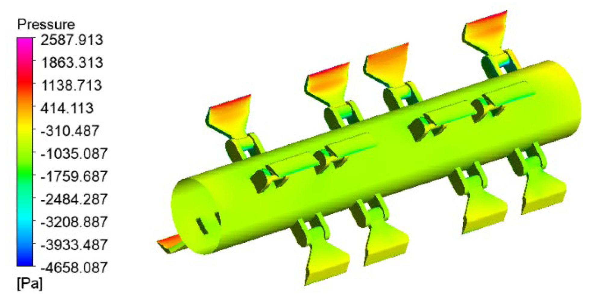
Figure 13.
Pressure cloud map of inlet and P1~P7 section at a speed of 2100 r/min.
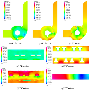
The pressure distribution of the P1 to P7 sections is presented in Error! Reference source not found.. From the P1 ~ P3 and P5 cross-section pressure clouds, it can be seen that in the whole crushing device, the pressure in the feed inlet area and the discharge pipe close to the exit area pressure change is not big; The average values of the pressures of P1 ~ P3 sections are -512.273 Pa, -657.452 Pa and -585.193 Pa, respectively, which shows that in the crushing device, the pressure value of the central area where the P2 section is located is lower; In the knife roller rotary area due to the high-speed rotation of the knife roller, the pressure fluctuation is more obvious, in the rotary area to form a large area of negative pressure area, and the closer to the knife shaft surface the lower the negative pressure value. The P4 cross-section pressure cloud reacts to the pressure distribution at the junction of the inlet area and the crushing chamber, where the pressure value fluctuates less and the average pressure value is -80.954 Pa. P7 cross-section pressure map can be seen, in the cross-section of the discharge pipe near the rotating domain of the existence of negative pressure areas, and due to the influence of the right spiral arrangement of the hammer claw, the right side of the discharge pipe pressure value is lower than that of the left side, the pressure value of the region presents a gradient distribution, so the hammer claw adopts the right spiral arrangement of the vibration is low, the cutter shaft is uniformly affected by the characteristics of the force, but it is necessary to consider the arrangement of the influence of the uniformity of the material thrown.
- 4.
- (3) Characterisation of the flow field in the crushing chamber at different knife roller speeds
The rotational speed of the crushing knife roller is the key working parameter of the branch crushing and collecting device, and this study will further analyse the effect of rotational speed on the branch feeding, crushing and crushed material throwing by comparing the distribution of airflow field in the crushing device under different rotational speeds The speed of the crushing knife roller was set to 1.7×10³ r/min, 2.1×10³ r/min and 2.5×10³ r/min, and after the calculation, the post-processing software CFD-Post was used to calculate the inlet flow rate and generate the inlet pressure map and cross-section flow map for analysis and research.
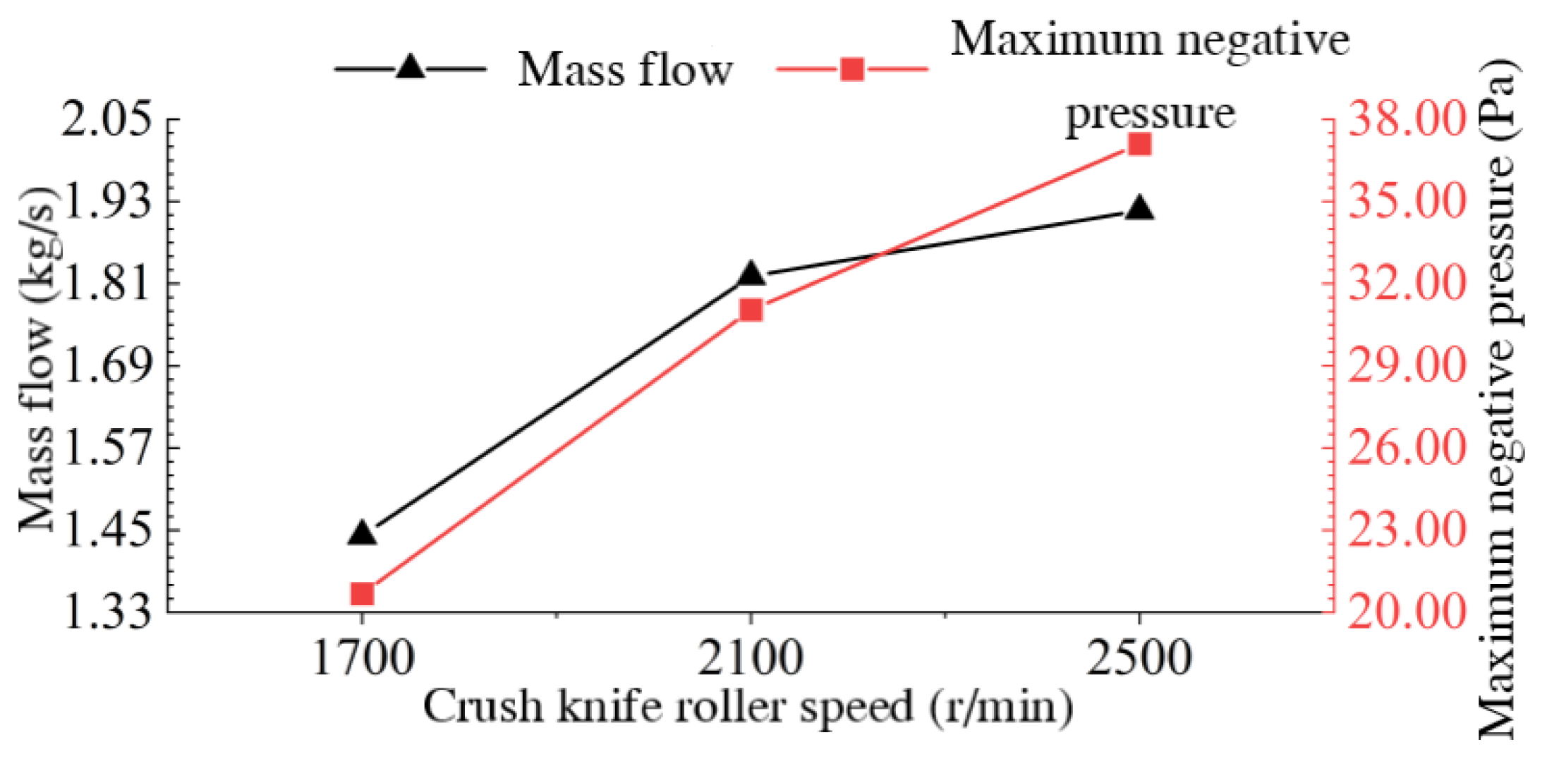
Error! Reference source not found. (a) ~ (c) respectively represent three knife roller speed inlet pressure cloud, three speed inlet area are large negative pressure area, and positive pressure area are present at the bottom of the inlet position, which is related to the bottom of the existence of vortex, the maximum value of the inlet negative pressure were: 20.65 Pa, 31.05 Pa, 37.16 Pa, can be seen with the increase in rotational speed of the entrance of the negative pressure maximum value are increasing. The maximum value of inlet negative pressure is increasing with the increase of rotational speed. As can be seen in Error! Reference source not found., the inlet mass flow rates at the three rotational speeds are 1.44 kg/s, 1.82 kg/s, and 1.92 kg/s, respectively, and as the rotational speed increases, the inlet flow rate also increases. Both the negative pressure at the inlet of the crushing unit and the increase in flow rate will induce more airflow from the inlet into the crushing unit, so increasing the speed of the crushing knife rollers during machine operation will be beneficial to the feeding of the branches.
Figure 14.
Cloud map of inlet pressure at different rotational speeds.

Figure 15.
Inlet mass flow rate and maximum negative pressure at different blade roller speeds.
Error! Reference source not found. shows the flow line diagrams of representative cross sections P2 and P3 at different knife roller speeds, and it can be analysed that the airflow velocity on cross sections P2 and P3 increases as the speed increases with the speed. Three rotational speeds under the cross-section P2 streamline distribution changes are not large, and are in the inlet and the knife roller rotating area and the junction of the discharge pipe to produce a vortex of similar size, so the knife roller speed changes on the cross-section P2, that is, the centre of the crushing device region of the air flow mobility of the impact is small, only on the region of the airflow speed.
Figure 16.
P2, P3 cross-sectional streamline diagram at different speeds.
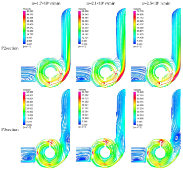
Vortices of different shapes and sizes are generated in the inlet area of cross-section P3, at the junction of the knife roll rotation area and the discharge tube, at the lower right side of the discharge tube and at the middle left side of the discharge tube. When the speed is increased from 1.7×10³ r/min to 2.5×10³ r/min, the vortex at the inlet area moves to the lower left, the vortex in the middle area of the left side of the discharge tube moves to the upper side and the vortex strength there is obviously strengthened at 2.5×10³ r/min; when the speed is increased from 1.7×10³ r/min to 2.1×10³ r/min, the vortex at the junction of the rotating area of the knife roller and the discharge tube and at the lower right side of the discharge tube is weakened. However, when the rotational speed is increased from 2.1×10³ r/min to 2.5×10³ r/min, the vortex at the junction between the rotating area of the knife roller and the discharge tube is significantly enhanced, and the vortex area at the right bottom of the discharge tube is significantly larger, and the diameter is almost equal to the cross-section width of the discharge tube. Therefore, the variation of the speed of the crushing knife roller has a large effect on the airflow velocity as well as the airflow mobility at the cross-section P3.
Comprehensive analysis of the above, with the increase in the speed of the crushing knife roller speed, the crushing device at the exit of the air flow rate increases, will increase the throwing speed of the material to a certain extent, but the knife roller speed is too high will also lead to the crushing device in part of the region of the enhancement of the vortex, which affects the inlet of the branches of the feed and the discharge pipe crushed material thrown out.
Based on the tool dynamics analysis, branch crushing process simulation analysis and the results of this section of the crushing device under the airflow field characteristics of different knife roller speed, combined with the range of tractor output shaft speed, implement ratio and crushing power consumption and other factors, the final determination of the crushing knife roller speed range of 1.8×10³ ~ 2.22×10³ r / min.
4. Crushing Knife Roller Modal Analysis
Crusher crushing operations, crushing knife roller rotation is the main source of vibration of the machine, and once the resonance, will cause the machine parts connected to loose, and even some parts of the hazard of cracking, so it is necessary to carry out a modal analysis of the knife roller, in order to determine the crushing of the knife roller modal attributes and the relationship between the frequency of excitation due to the rotation of the predictive dynamic performance of the equipment[21], so as to avoid resonance of the branch crushing and collecting machine in the work of resonance phenomenon. The phenomenon of resonance in the operation of the branch crusher and collector can be avoided.
In the theory of classical mechanics, the kinetic equation of an object is shown in equation (8):
In the equation:
- [M]——System quality matrix;
- [C]——System damping matrix;
- [K]——Stiffness matrix;
- ——System unit node acceleration vector;
- ——System unit node velocity vector;
- ——System unit node displacement vector;
- ——Force vector.
In practice, the structure's intrinsic frequency and vibration mode are affected by its own damping is very small, can be ignored. If the structure is free vibration in the analysis, the structural modes are determined only by its own characteristics and the external load has nothing to do with, so that the force vector F(t) = 0 in equation. (8), ignoring the damping [C], the dynamic equations of undamped free vibration is:
A structure in a state of free vibration with each mass point vibrating in simple harmonic vibration near its equilibrium position[22], and the expression for the vector of vibration displacements of the mass points is:
In the equation:
- ——Amplitude vector;
- ω——Frequency of oscillation pattern.
Associative equation (9) and (10) can be obtained.
The eigenvalue is ωi2, ωi is the self-oscillating circumferential frequency, i is the number of degrees of freedom,the eigenvector corresponding to the eigenvalue ωi2 is the vibration mode corresponding to the self-oscillation frequency f = ωi/2π[23,24,25]. Show that modal analysis is essentially the process of solving eigenvalues and eigenvectors, also known as modal extraction[26].
4.1. Crushing Knife Roll Modelling and Meshing
SolidWorks 2020 software is used to establish a three-dimensional model of the crushing knife roller, omitting details such as keyways and threads that do not have much influence on the modal analysis of the system, saving the file in Parasolid (.x_t) format, invoking the Model module in ANSYS Workbench 2022 R1, importing the three-dimensional model, and using the DesignModeler plug-in to perform co-nodal operations on the components in the geometry. The generated new parts are given the corresponding material, in which the material of the knife shaft and knife seat is Q235, the material of the hammer claw is 65Mn, and the material of the axle head is No.45 steel, and the three kinds of steel have similar values of density, modulus of elasticity and Poisson's ratio parameter, and the following materials are used for each part of the crushing knife roll in the simulation: the density is 7.85×10³ Kg·m-3, modulus of elasticity is 210 GPa, and Poisson's ratio is 0.3[27].
All contacts in the connection are removed and the model is automatically meshed, where the cell size is set to 10 mm and the dimensional resolution is set to default. The division produced a total of 3.07×10⁵ grid nodes and 1.69×10⁵ entity cells. Afterwards, cylindrical support constraints are added at the mating point of the shaft head and bearing for constrained modal analysis, and no external force is applied to the whole model[28].
Figure 17.
Grid division diagram of crushing knife roller.
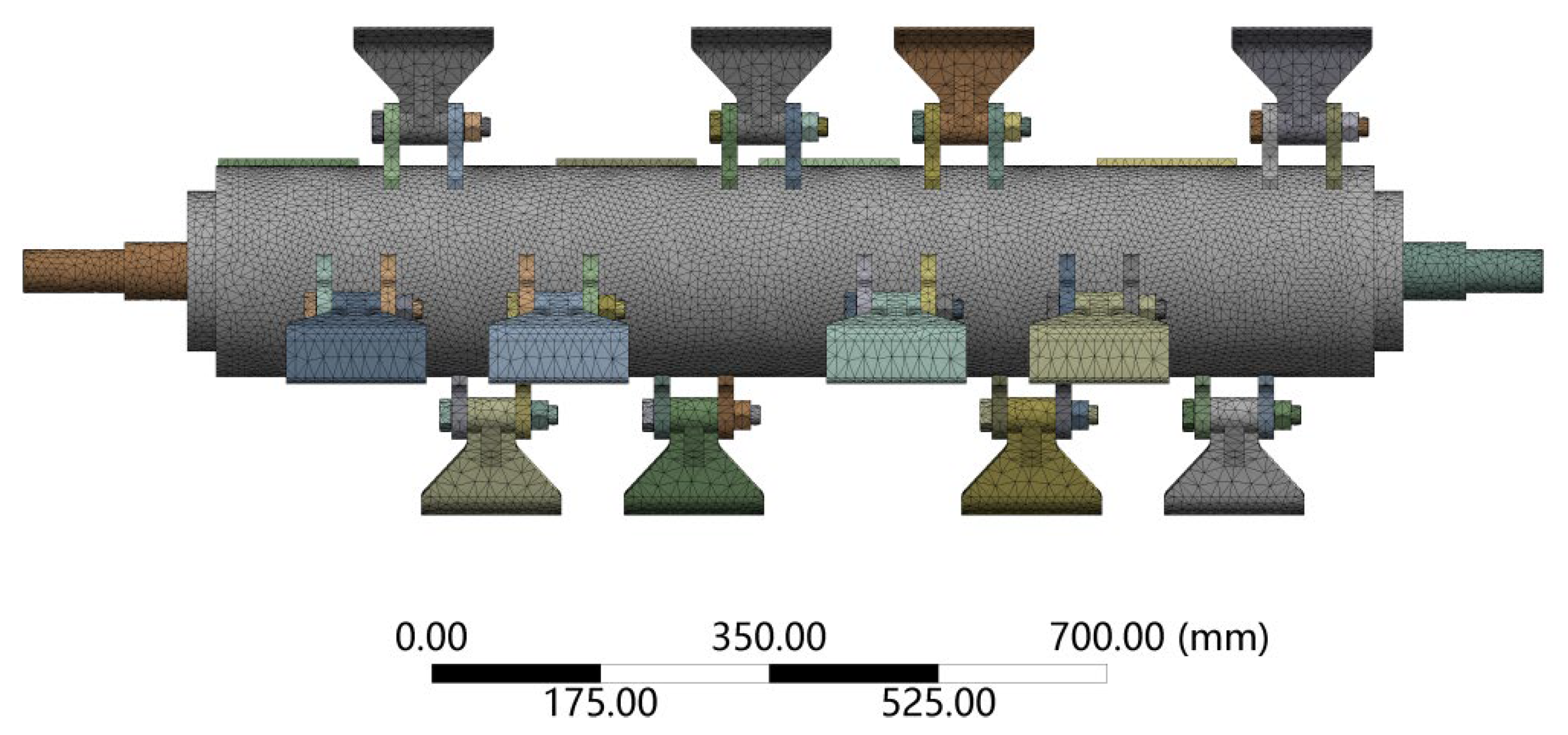
For the mesh quality metrics, ANSYS Workbench has aspect ratio, Jacobi ratio, skewness, maximum corner angle and warpage angle, etc. Skewness is one of the commonly used criteria for meshing quality, and the closer the skewness is to 0, the better the mesh quality is. The average value of the mesh skewness of the knife roller model is 0.43. Referring to the comparison table of skewness and mesh quality in the literature[29], it can be seen that the mesh classification is "Good", which meets the computational accuracy requirements for the subsequent modal analysis of the knife shaft.
4.2. Crushing Knife Roll Modal Analysis Results
Generally speaking, the low-order vibration of the mechanism of the dynamic impact of the device is more significant, so the selection of the first 5 to 10 orders for analysis has been sufficient[21,30], this paper combines the characteristics of the crushing knife roller and similar devices modal analysis literature[31], analysed the first 6 orders of the crushing knife roller natural frequency and vibration pattern. The results of the modal analysis are summarised, and the intrinsic frequencies of each order are shown in Table 3. The inherent frequencies of each mode of the crusher roll. In order to facilitate the analysis, the deformation generated by the crushing knife roller is enlarged to show that the deformation scale factor is taken as 12, and the vibration pattern of each order is shown in Figure 18. Modal Shape of the Grinding Knife Roller at Each Stage.
Table 3.
The inherent frequencies of each mode of the crusher roll.
| Modal step | 1 | 2 | 3 | 4 | 5 | 6 |
| Intrinsic frequency/Hz | 137.42 | 221.03 | 221.26 | 435.89 | 492.54 | 493.29 |
Figure 18.
Modal Shape of the Grinding Knife Roller at Each Stage.
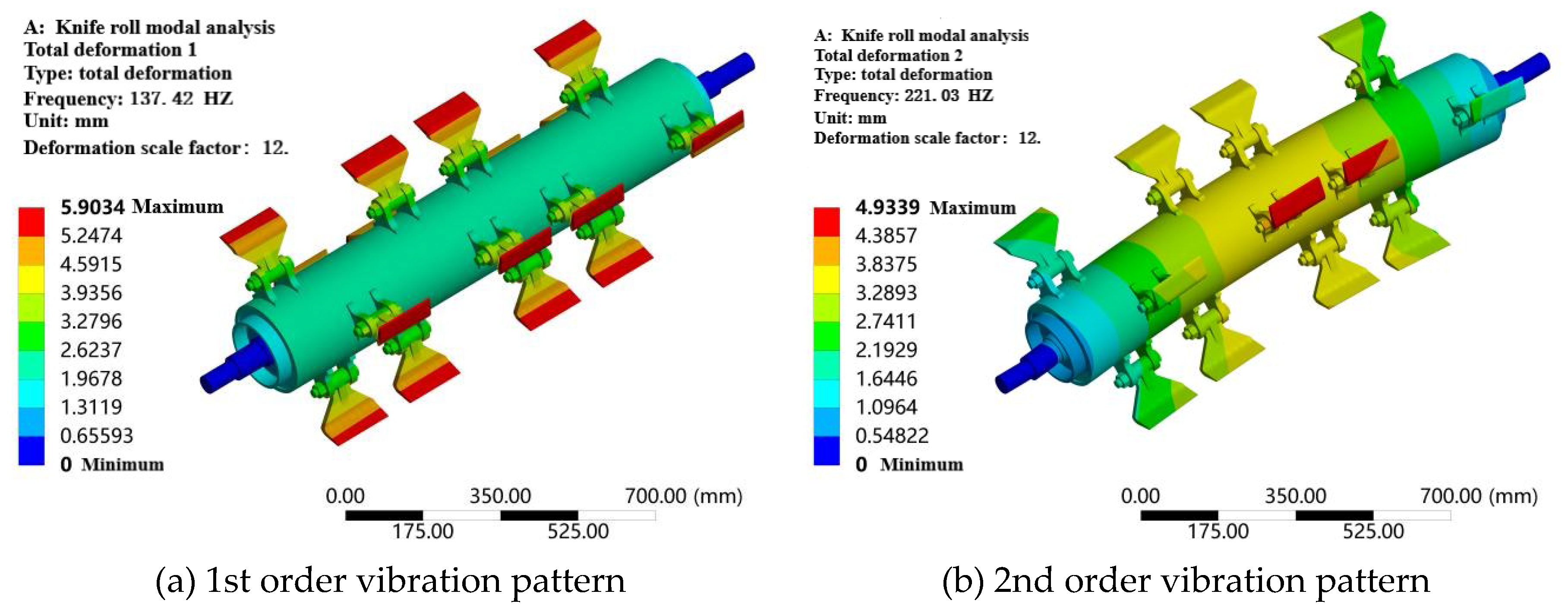
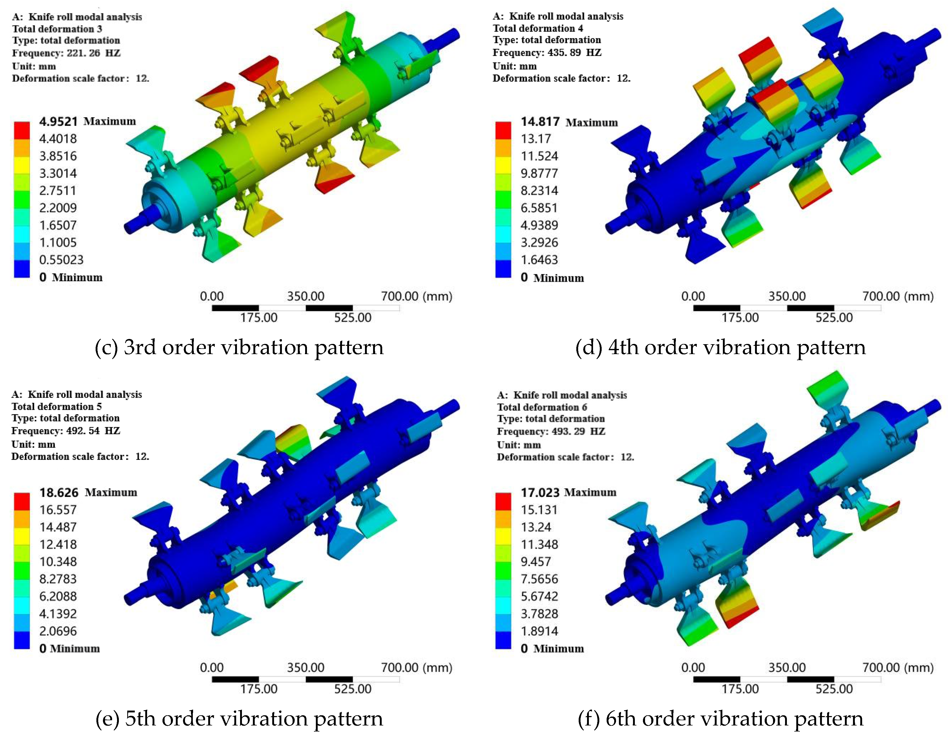
As can be seen from Error! Reference source not found., in the 1st order modal vibration mode, the deformation of the crushing knife roller for the overall radial tensile deformation and axial compression deformation; in the 2nd and 3rd order modal vibration mode, the crushing rollers show a large bending deformation, and this deformation is mainly concentrated in the middle part of the knife rollers, and the deformation at both ends is relatively small; in the 4th order modal vibration mode, the crushing shaft in the middle of the radial compression deformation, and the deformation of the two ends is relatively small; 5th and 6th order modal vibration modes in the crushing knife roller deformation is S-shaped, near the head of the knife shaft to produce the opposite direction of radial deformation, the knife roller in the middle position is not deformed. In the 4th order modal vibration mode, the middle of the crushing shaft produces part of the radial compression deformation, and the deformation at both ends is small; in the 5th and 6th order modal vibration modes, the crushing knife roller deformation is in the form of S, and the radial deformation in the opposite direction is produced close to the head of the knife shaft, and the deformation in the middle of the knife roller is small. At the same time combined with can be seen, the 2nd and 3rd order, 5th and 6th orders of solid frequency are similar and the vibration patterns are similar.
Knife roller operation at a maximum working speed of 2.22×10⁵ r/min, according to the frequency and speed of the relationship between the formula (12), the operating frequency of 37 Hz, much smaller than the crushing knife roller lowest-order modal intrinsic frequency of 137.42 Hz, the crushing knife roller design is reasonable, the machine will not resonate during operation.
- v ——Critical speed,r/min;
- f——Intrinsic frequency,Hz.
5. Field Trials
Test time and place: October 2023, experimental field, Jinghe County, Bortala Bortala Mongol Autonomous Prefecture, Xinjiang Uygur Autonomous Region; test materials: winter pruned branches of Keresen Vineyard, grapevine planted with row spacing of 6 m and plant spacing of 0.6 m, average width of the pile of branches after pruning of 1.2 m, average height of 0.2 m. The average water content of the branches (including the leaves) was 61.48%, and the diameter was ≤ 60 mm.
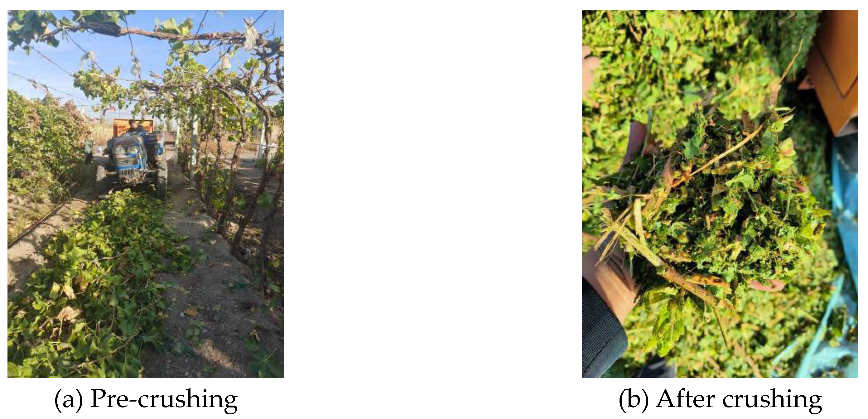
Test apparatus: grape branch crushing and collecting machine prototype, tractor, tape measure, vernier calipers, pruning shears, table scale, electronic balance, drying box, tachometer (DT-2236B), stopwatch, dismantling tools. As can be seen from the figure, the field verification test crushing effect is basically similar to the theoretical value, and the prototype can meet the design requirements.
Figure 19.
Crushing effect.
6. Conclusions
(1) Through numerical simulation, using LS-DYNA software, combined with the measurement data of grapevine branch material characteristics in Chapter 2, the branch crushing process was simulated, the crushing process of the branch into the crushing chamber was analysed, and the effects of different knife roller speeds and knife edge angle on the cutting resistance of the knife to crushing the branch were analysed; the characteristics of the airflow field in the crushing device were analysed using Fluent software, and the flow field distribution characteristics were compared under different knife roller speeds. The flow field characteristics in the crushing device were analysed by Fluent software; the flow field distribution characteristics under different knife roller speeds were compared, and the influence of the speed on branch feeding, crushing and conveying was investigated, and the speed range of the knife roller was finally determined, which can be used as a reference for the subsequent field test of the prototype; the modal analysis of the crushing knife roller was carried out on the basis of the ANSYS/Model module in order to prevent the resonance phenomenon from occurring in the operation of the machine.
(2) Branch crushing process simulation analysis, it is concluded that the branch in the destruction process not only exists in the cutter cutting, there is also the cutting of the opposing side of the bending fracture; with the increase in the speed of the knife roller, the cutting resistance of the tool continues to increase, the cutting resistance reaches 2.69×10³ N at 2.5×10³ r/min; different tool cutting angle cutting simulation, the cutting angle of 55° when the cutting resistance of the tool cutting the smallest, 1.86×10³ N, the blade angle of more suitable for the cutting of grapevines. The cutting angle is more suitable for the crushing and cutting of grapevine branches.
(3) In the simulation analysis of the flow field of the crushing device, the velocity and pressure distribution law of the representative area of the crushing device are summarized; it is concluded that with the increase of the knife roller speed, the inlet flow and negative pressure of the crushing chamber are increasing, and the inlet flow and negative pressure at a speed of 2500 r/min are 1.92 kg/s and 37.16 Pa respectively, which is conducive to the feeding of the branch, but the speed is too high and it will also lead to the enhancement of vortex in some areas of the crushing device, which will affect the feeding of the branch at the entrance and the throwing of the crushed material in the discharge pipe. Crushing device in some areas of the vortex enhancement, which in turn affects the entrance of the branch feeding and discharge pipe crushed material thrown, and combined with the analysis of the previous section, the final determination of the crushing knife roller speed range of 1.8×10³ ~ 2.22×10³ r/min. crushing knife roller modal analysis, the analysis of the first six orders of the knife roller natural frequency and vibration, the crushing knife roller the lowest order of the modal natural frequency is 137.42 Hz, much larger than the crushing knife roller operating speed. Far greater than the crushing knife roller operating frequency of 37 Hz, will not resonate.
Author Contributions
resources, Z.W.; data curation, L.S.; writing—original draft preparation, L.H.; writing—review and editing, S.C.; visualization, P.B.; supervision, S.C.; project administration, L.H.. All authors have read and agreed to the published version of the manuscript.
Funding
This work was supported by the Xinjiang Corps Young and Middle-aged Science and Technology Innovation Leaders Program and the Innovation Team of Xinjiang Academy of Agricultural and Reclamation Sciences under project numbers 2020CB031 and NCG202302, respectively.
Institutional Review Board Statement
Not applicable.
Informed Consent Statement
Not applicable.
Data Availability Statement
The data presented in this study are available on request from the corresponding author.
Acknowledgments
This work was supported by the Program for Young and Middle-aged Leading Talents in Science and Technology Innovation of Xinjiang Corps (2020CB031) and the Innovation Team of Xinjiang Academy of Agricultural and Reclamation Sciences (NCG202302). The authors are grateful to anonymous reviewers for their comments.
Conflicts of Interest
The authors declare no conflict of interest.
References
- Chen Yang. Design and test of bionic stubble cutter based on the characteristics of cricket cutter leaf[D]. Anhui: Anhui Agricultural University, 2018. (in Chinese).
- Zou, Y. Research on bionic technology of crushing key components based on corn kernel shaft return rotting[D]. Jilin: Jilin University, 2023. (in Chinese).
- Chen Wentao. Research on mechanical properties of mushroom grass stalks at maturity and cutting simulation analysis[D]. Fujian: Fujian Agriculture and Forestry University, 2016. (in Chinese).
- Zhao Fangcheng. Application of LS-DYNA to the simulation of reinforced concrete column damage[D]. Gansu: Lanzhou University of Technology, 2009. (in Chinese).
- Wang Jianwei, Jin Xianlong, Cao Lufen, et al. Parallel computation of dynamic response of tunnel contact channel under train load[J]. Journal of Shanghai Jiao Tong University, 2012, 46(04): 591-595. (in Chinese).
- Xiong Xiangyu, Lei Zhengbao. Optimised design of shear-extrusion energy-absorbing guided crash cushion[J]. Mechanical Strength, 2023, 45(5): 1174-1180. (in Chinese).
- YANG J,XU G J,CAI C S, et al. Crash performance evaluation of a new movable median guardrail on highways[J]. Engineering Structures, 2019, 182(3): 459-472.
- Guo W, Jiang Z, Zhong H, et al. Impact of online mixing via KSM on the accuracy of ingredient deposition in manufacturing FGMs[J]. International Journal of Mechanical Sciences, 2023, 241: 107971.
- Wang H, Sun W, Zhao C, et al. Dynamic Modeling and Control for Tilt-Rotor UAV Based on 3D Flow Field Transient CFD[J]. Drones, 2022, 6(11): 338.
- Zheng Zhiqi. Research on corn stover picking and crushing furrow burying field return machineD]. Beijing: China Agricultural University, 2017. (in Chinese).
- Wang Fujun. Research progress of rotating turbulence calculation model for fluid machinery[J]. Journal of Agricultural Machinery, 2016, 47(02): 1-14. (in Chinese).
- Xiong Aokui. Review of turbulence model theory[J]. Journal of Wuhan University of Technology (Transportation Science and Engineering Edition), 2001(04): 451-455. (in Chinese).
- Tutar M, Oguz G. Large eddy simulation of wind flow around parallel buildings with varying configurations[J]. Fluid Dynamics Research, 2002, 31: 289-315.
- Li Dapeng. Research on adsorption picking technology and experiment on yellow silage corn stover with high ground clearance[D]. Inner Mongolia: Inner Mongolia Agricultural University, 2023. (in Chinese).
- Yu Ping. Engineering fluid mechanics [M]. Beijing: Science Press, 2008. (in Chinese).
- MA Mang, WANG Cong, ZHANG Yongxue, et al. Research on hydraulic characteristics of separator for pre-separation of high water content thick oil[J]. Petroleum Machinery, 2017, 45(2): 73-77. (in Chinese).
- Shen Dezhang, Zhang He, Chang Zigang, et al. Numerical simulation of two-phase flow with high-speed rotation of an external turbine for underwater munition fuzes[J]. Journal of Aerodynamics, 2014, 32(2): 184-189. (in Chinese).
- TANG Zerun, ZHANG Baiyun, JIANG Jin, et al. Analysis of cavitation flow characteristics of multi-orifice piston flow regulator[J]. Journal of Hydropower Generation, 2021, 40(04): 50-58. (in Chinese).
- Zhao, Y. Analysis of flow field characteristics and aerodynamic noise in a new type of forage kneader [D]. Inner Mongolia: Inner Mongolia University of Technology, 2023. (in Chinese).
- Zhang Zhiqiang. Research on the design and straw movement characteristics of corn stalk crushing and throwing return machine[D]. Beijing: China Agricultural University, 2018. (in Chinese).
- Zheng Zhiqi, He Jin, Li Hongwen, et al. Design and test of movable and fixed knife support slip-cutting straw crushing device[J]. Journal of Agricultural Machinery, 2016, 47(S1): 108-116. (in Chinese).
- Yin Yuefeng. Development of new disc roll crusher and its key components characteristics research[D]. Henan: Zhengzhou University, 2013. (in Chinese).
- Ren Zichao. Design and experimental research on shear device of sea buckthorn harvester[D]. Xinjiang: Shihezi University, 2023. (in Chinese).
- V. C, R. L, F. M. The modal analysis of a motorcycle in straight running and on a curve[J]. Meccanica: Journal of the Italian Association of Theoretical and Applied Mechanics, 2004, 39(1). [CrossRef]
- Étienne A, Pascal L, Luigi M. The modal stability procedure for dynamic and linear finite element analysis with variability[J]. Finite Elements in Analysis & Design, 2010, 4. [CrossRef]
- Dou Tan. Design and experimental research on rice straw straw crusher[D]. Heilongjiang: Northeast Forestry University, 2022. (in Chinese).
- Cheng Daxian. Mechanical design manual[M]. Beijing: Chemical Industry Press, 2007. (in Chinese).
- Niu Guoliang, Li Bin, Liu Yang, et al. Vibration analysis and optimisation of vertical straw crushing and returning machine frame[J]. Journal of Gansu Agricultural University, 2021, 56(05): 185-194. (in Chinese).
- Yan Yirou. Research on shower comfort and fluid characteristics of showerhead[D]. Beijing: Beijing Architecture University, 2019. (in Chinese).
- Bai Xuewei, Hao Yan, Bai Xin, et al. Design and test of pick-up device for self-propelled straw pelletiser[J]. Journal of Shenyang Agricultural University, 2021, 52(6): 697-707. (in Chinese).
- Xu Kai, Ge Yanyan, Xiao Maohua, et al. Design of a straw picking and cutting device[J]. International Journal of Agricultural and Biological Engineering, 2021, 14(6): 93-98. [CrossRef]
Disclaimer/Publisher’s Note: The statements, opinions and data contained in all publications are solely those of the individual author(s) and contributor(s) and not of MDPI and/or the editor(s). MDPI and/or the editor(s) disclaim responsibility for any injury to people or property resulting from any ideas, methods, instructions or products referred to in the content. |
© 2024 by the authors. Licensee MDPI, Basel, Switzerland. This article is an open access article distributed under the terms and conditions of the Creative Commons Attribution (CC BY) license (http://creativecommons.org/licenses/by/4.0/).
Copyright: This open access article is published under a Creative Commons CC BY 4.0 license, which permit the free download, distribution, and reuse, provided that the author and preprint are cited in any reuse.


