Preprint
Article

This version is not peer-reviewed.

Additively Manufactured Flexible EGaIn Sensor for Dynamic Detection and Sensing on Ultracurved Surfaces

A peer-reviewed article of this preprint also exists.

Submitted:

27 November 2024

Posted:

28 November 2024

You are already at the latest version

Abstract

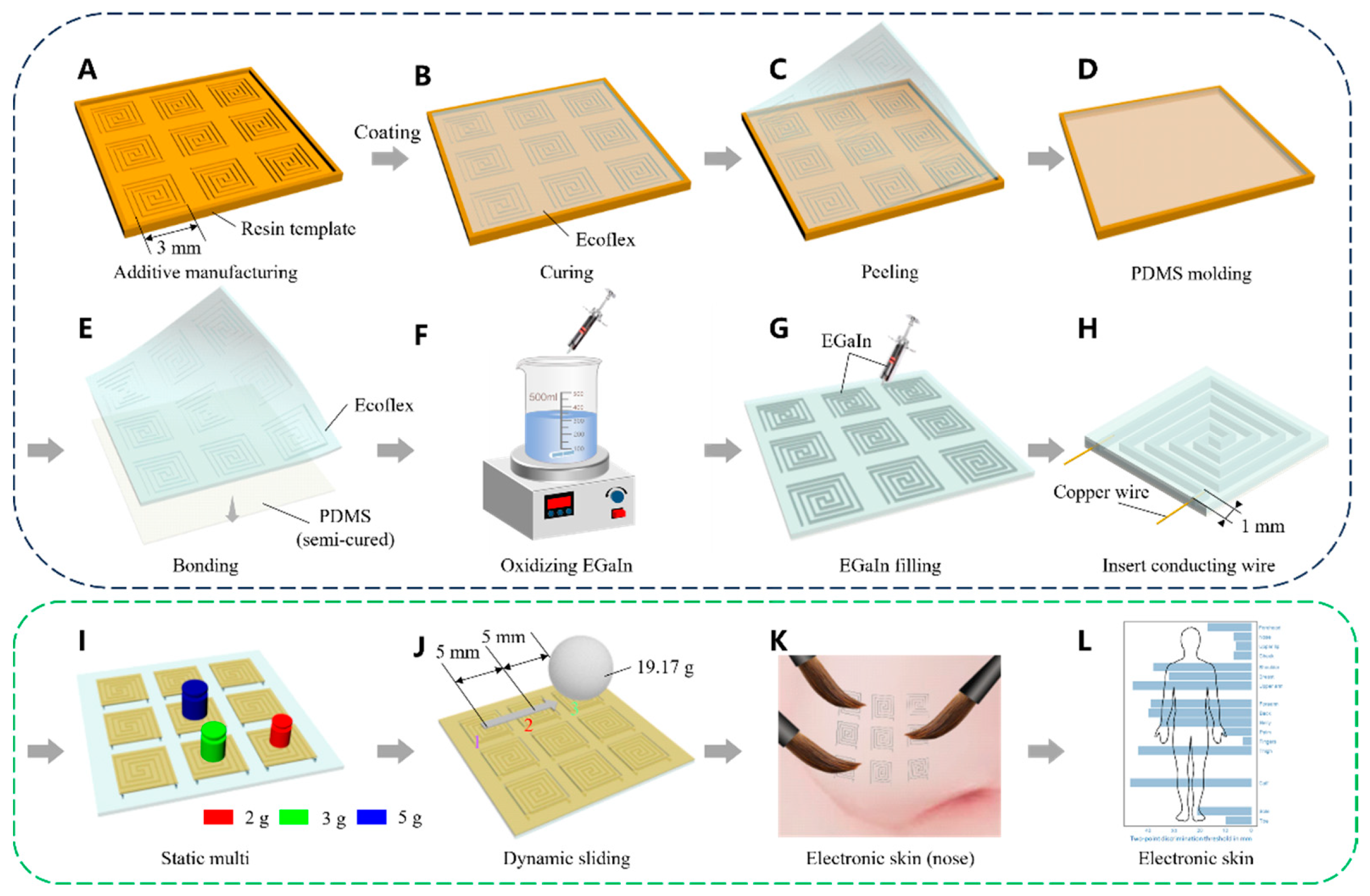
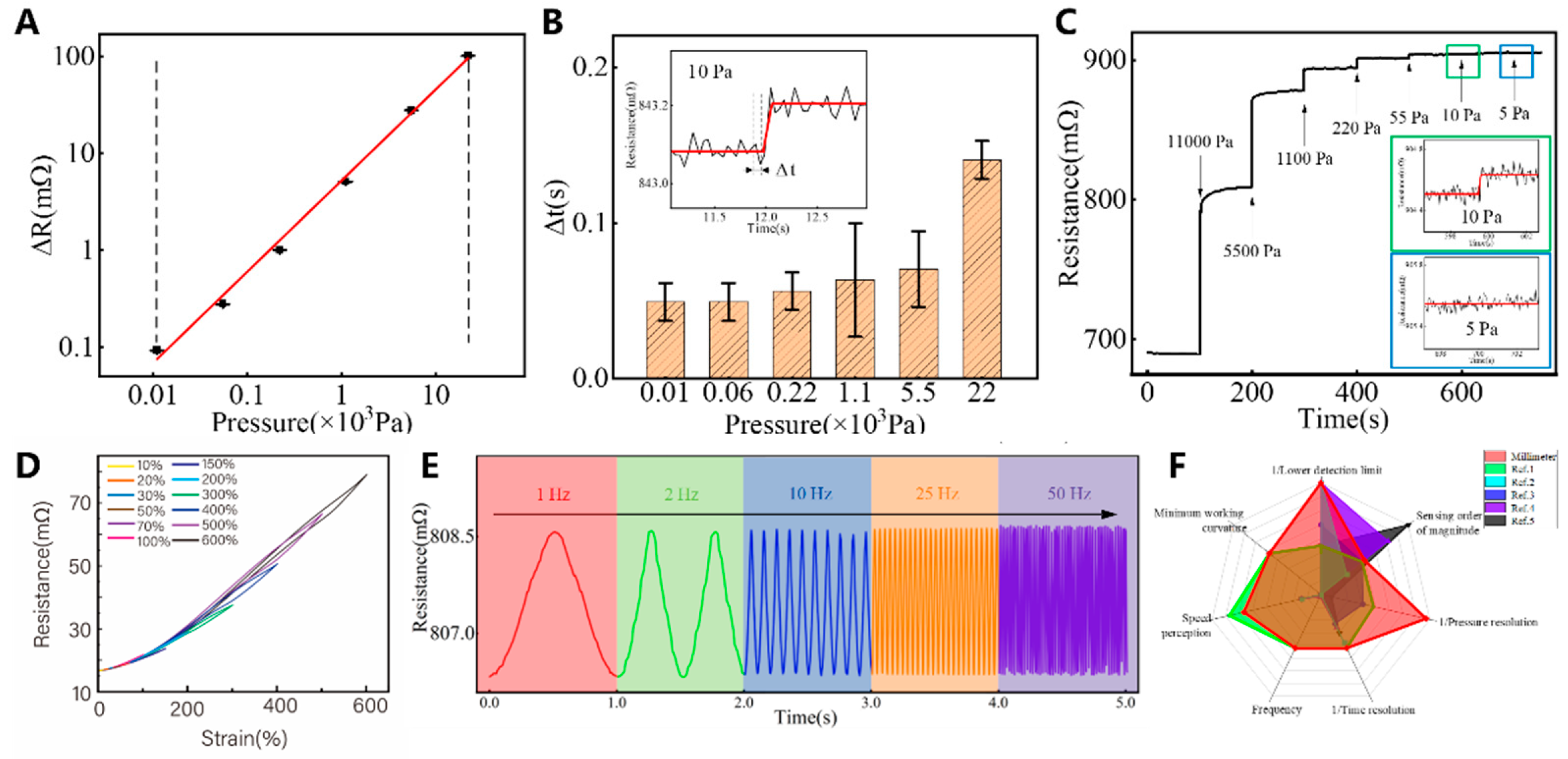
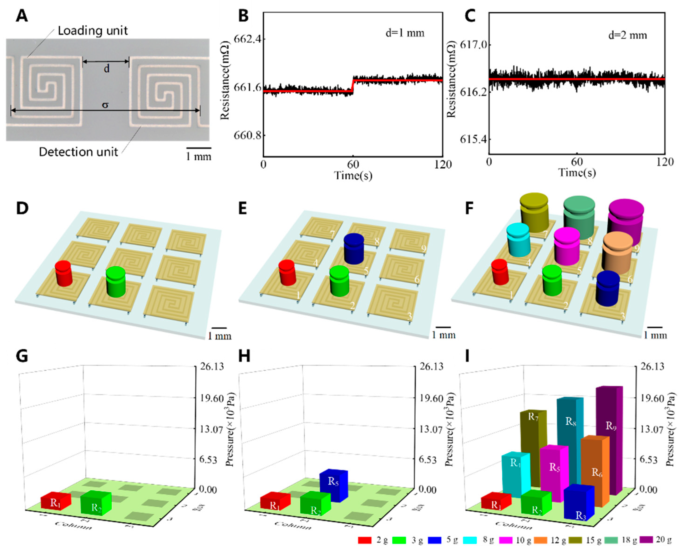
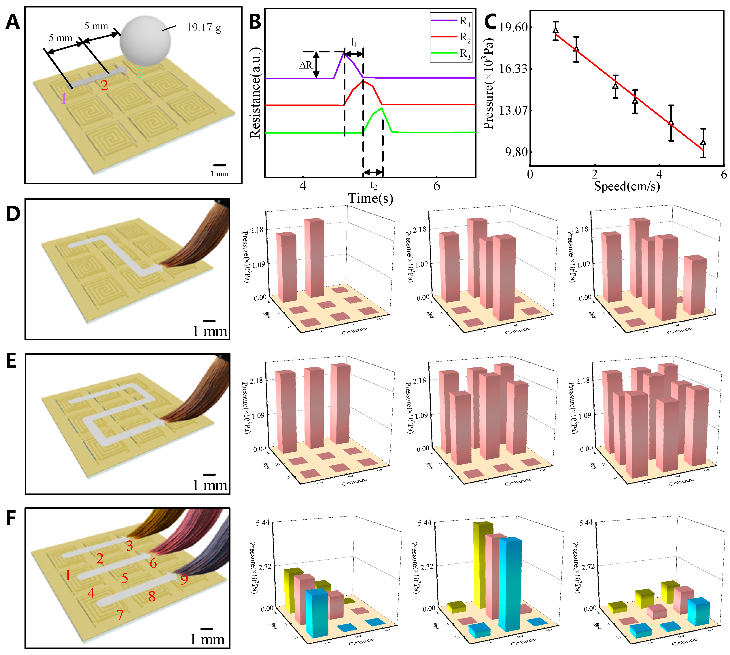
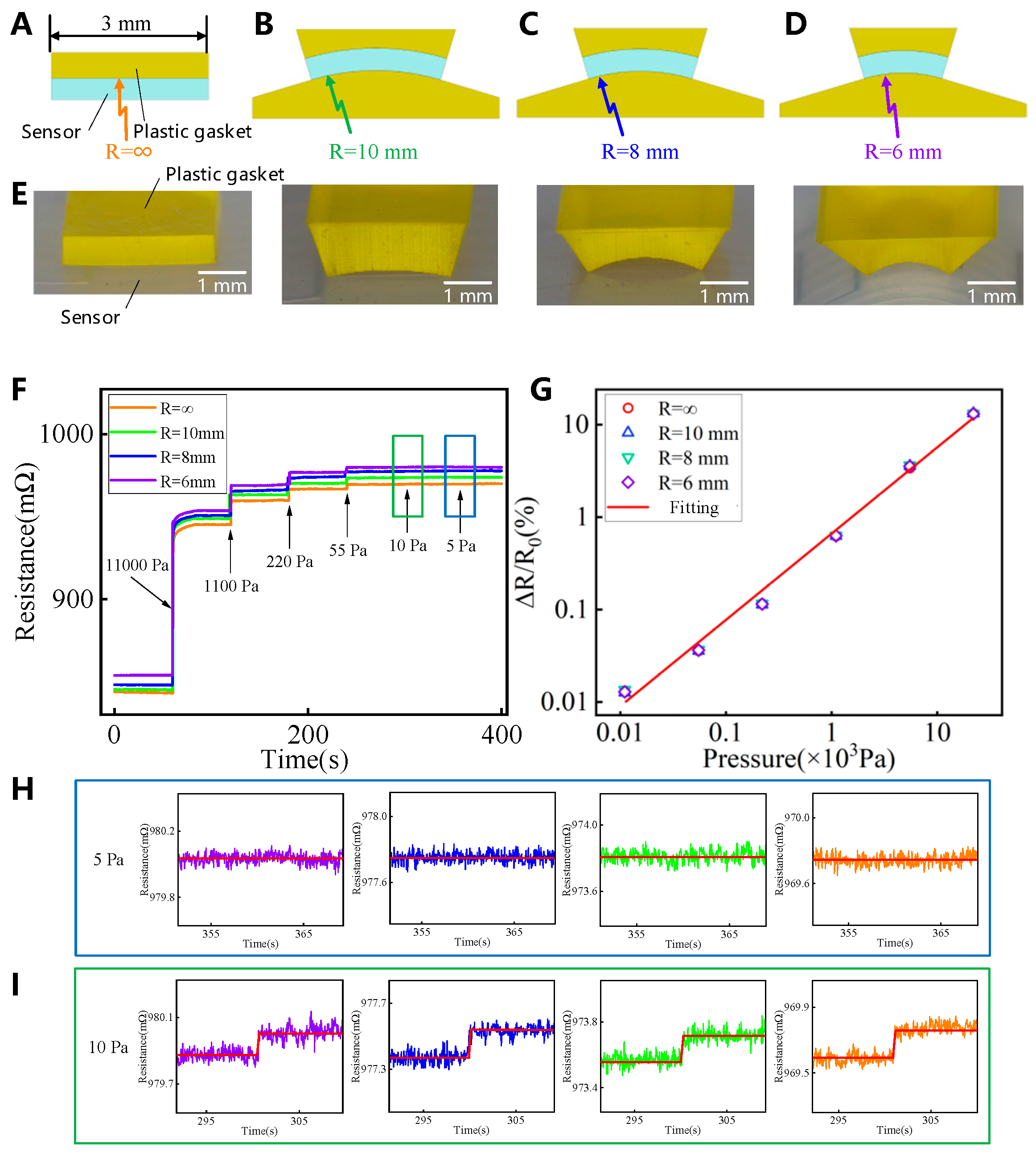
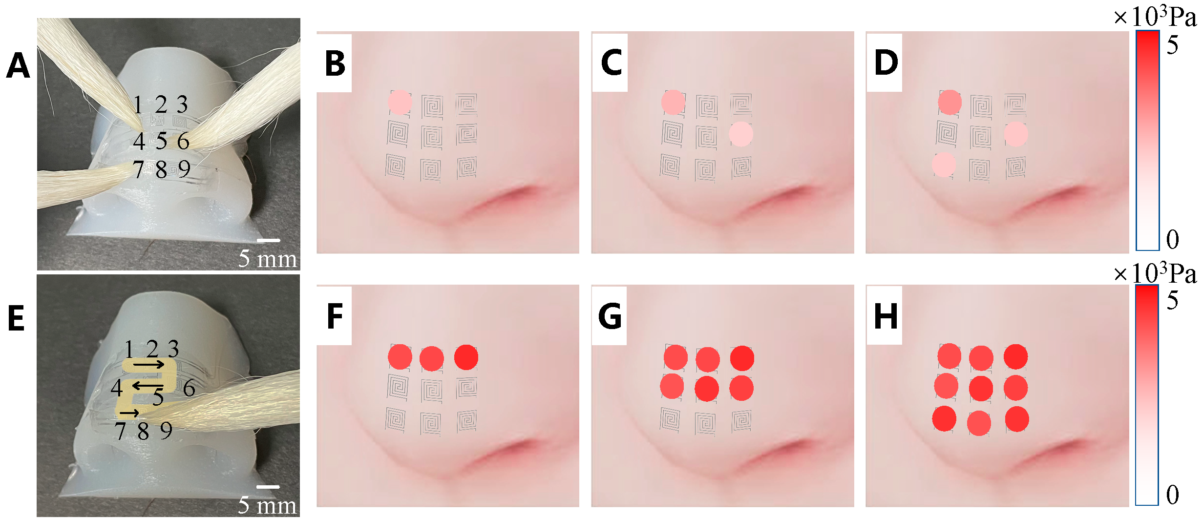
Electronic skin is widely employed in multiple applications such as health monitoring, robot tactile perception, and bionic prosthetics. In this study, we fabricated millimeter-scale electronic skin featuring compact sensing units using Boston Micro Fabrication S130 (a high-precision additive manufacturing device) and the template removal method. We used a gallium-based liquid metal and achieved an inner channel diameter of 0.1 mm. The size of the sensing unit was 3 × 3 mm². This unit exhibited a wide linear sensing range (10–22000 Pa) and high pressure resolution (10 Pa) even on an ultracurved surface (radius of curvature was 6 mm). Sliding was successfully detected at speeds of 8–54 mm/s. An artificial nose with nine sensing units was fabricated, and it exhibited excellent multitouch and sliding trajectory recognition capabilities. This confirmed that the electronic skin functioned normally even on an ultracurved surface.

Keywords: 
;  ;  ;  

1. Introduction

Electronic skin shows remarkable properties; for example, it achieves high conformity when affixed to nonuniform surfaces[1,2,3,4,5,6,7,8,9,10] and emulates the flexible properties of the human epidermis to facilitate supple tactile discernment[11,12,13,14]. It is widely used in health monitoring, human–robot interactions, and bionics[15,16,17,18]. Eutectic gallium-indium (EGaIn) is considered as the most promising material for fabricating electronic skin. Zhou et al. fabricated a flexible electronic device using polyvinyl-alcohol-encapsulated liquid gallium[19]. The device exhibited good durability and stability when it was bent and twisted owing to the flexibility of the substrate and liquid metal. Kramer et al. used photolithography to fabricate a graphic master. They employed stacking and layer-by-layer bonding through reverse molding to obtain a flexible polydimethylsiloxane (PDMS) substrate with double-layer serpentine channels. They infused these channels with EGaIn to obtain a wearable tactile keyboard[20]. The electronic skin utilized a quasiplanar intersection network con-structed using double-layer serpentine circuits to sense the position, intensity, and time of applied pressure based on the electrical signal response at an intersection. However, an external pressure of at least 100 kPa was required to cause a discernible change of approximately 5% in the output voltage. Yang et al. mixed EGaIn with Ecoflex using the sacrificial particle method to obtain a foamy composite elastomer[21]. Subsequently, liquid gallium was sprayed to prepare electrodes on both sides of the composite elastomer, which served as the dielectric layer[22,23,24,25,26,27,28,29]. The resulting flexible capacitive sensor array accurately identified the position of touch points[30,31,32,33,34,35,36,37]. The measurement precision decreased during bending. This was primarily attributed to the large size of the sensing unit, which experienced substantial perturbations under deformation. A reduction in the size of the sensing unit mitigated the impact of bending, thereby highlighting the importance of miniaturization.
The challenges in the miniaturization of sensing units include difficulties in EGaIn injection and complex sensor fabrication[38,39,40,41]. Typically, these issues are resolved by utilizing vacuum degassing and printed circuitry[42,43,44,45,46]. To address the requirement of a gas outlet when perfusing liquid metals, Dickey et al. used a vacuum chamber to remove gas from a microchannel and elastic substrate and showed that it was as small as several microns[47]. The filling of microns and branched dead-end structures is straightforward and requires minimal human intervention. Xi et al. reduced the line size to 0.1 mm and fabricated ultrathin micro-tubes with a diameter of approximately 0.12 mm in PDMS by employing thin copper wires. They injected EGaIn inside the tubes to obtain an ultrathin microtube sensor[48]. The sensor exhibited a minimum resolution of 5 mN and a high sensitivity of 68 N. The diameter of the sensor, which was comparable to that of human hair, allowed for the almost imperceptible monitoring of the human pulse. Zhang et al. printed liquid–metal lines on a prestrained PDMS substrate and subsequently released the strain, thereby decreasing the width and spacing of the metal lines[49]. The UV–ozone surface modification of a PDMS substrate prior to printing can improve the adhesion between a liquid metal and the substrate. This method can be utilized to reduce the resolution between metal lines to 0.03 mm. Park et al. proposed a high-resolution printing method for liquid EGaIn. This method was used to obtain patterns with a minimum linewidth of 1.9 mm through direct printing, which allowed for the preparation of stretchable electrodes with fine structures[50]. The relatively strong oxide skin maintained the printed 3D structure after printing. We presented the results for centimeter-level electronic skin in our previous work[51], where the resistance drift was significant in environments with small curvature radii. Despite the implementation of diverse methodologies and advancements, mass production of liquid metal flexible sensors remains a significant challenge. The complex fabrication processes have severely hindered their practical and widespread application. Therefore, a new manufacturing method must be developed, and the associated challenges must be resolved.
In order to address mitigate signal shift on highly curved surfaces, we fabricated electronic skin using the template removal method. This method is both simple and cost-effective, offering a feasible approach for the mass production of EGaIn sensor arrays.The size of a sensor unit was 3 × 3 mm2, and its linear sensing range was 10–22000 Pa with a pressure resolution of 10 Pa on an ultracurved surface (radius of curvature was 6 mm). The spatial resolution was 8 mm, which was comparable to that of the human nose[33]. A critical spacing of 2 mm was used to prepare a 3 × 3 mm2 sensing array that could accurately sense multitouch and sliding tracks on an ultracurved surface while detecting motion speeds of 8–54 mm/s. Our sensor unit is sufficiently flexible to be applied to ultracurved surfaces while providing excellent sensing performance. Furthermore, it has high potential for applications in health monitoring and robotics, thereby advancing the field of tactile sensing technology and addressing key challenges in curved surface sensing.

2. Materials and Methods

We used EGaIn as a conductive functional material to prepare modular electronic skin using the template removal method. First, a predesigned small-scale circuit pattern and mold base plate were printed as resin templates (Figure 1A) using Boston Micro Fabrication S130. The size of the sensing area was 3 × 3 mm2, and the circuit density was 3.2 mm-1, and the circuit width was 0.1 mm. The thickness of the sensing layer was 1 mm, ensuring good mechanical strength while keeping the sensor as thin as possible. Subsequently, the sample was coated with Ecoflex, heated, and cured at 45 °C (Figure 1B). The cured Ecoflex was peeled off such that the circuit pattern in the resin template was successfully transferred to the bottom surface of the flexible Ecoflex substrate (Figure 1C). Then, a PDMS coating was applied to a blank mold and heated at 45 °C for an appropriate duration to obtain the initial shape, resulting in the formation of a semicured PDMS film (Figure 1D). The thickness of the PDMS substrate was 1 mm. The peeled flexible Ecoflex substrate and semicured PDMS film were further heated and cured at 45 °C until they were completely bonded (Figure 1E). In addition, when preparing small-scale electronic skin, pure EGaIn is prone to causing open circuits due to its high surface tension and poor wettability. We address this issue by controlled oxidative modification of EGaIn to reduce its surface tension. The specific method involves mixing EGaIn with a NaOH solution and stirring with a magnetic stirrer to oxidize the surface layer, forming gallium oxide, which is then fragmented and dispersed into the interior of EGaIn. Stirring for 4 hours completes the modification process (Figure 1F). Subsequently,The oxidized and modified EGaIn was injected into the circuit channel using a small syringe (Figure 1G) and then guided out through ports on both sides using copper Cu wires (Figure 1H). The copper (Cu) wire used in our sensor had a diameter of 0.035 mm, was inserted into the channel to a depth of approximately 1 mm and then sealed with epoxy resin AB glue (the A and B parts of the glue was pre-mixed in 1:1 portion for 5 min, and then dried at 30℃ for 5 h), resulting in modular electronic skin with a size of 3 × 3 mm2.This electronic skin exhibited a high level of integration, thereby achieving accurate and sensitive recognition and the perception of static touch and dynamic sliding under external pressure loads (Figures 1I and J). The resulting electronic skin exhibited excellent touch performance (Figure 1K),and can be applied to more complex parts of the human body (Figure 1L).

3. Results and Discussion

Figure 2 shows the pressure resolution, response time, linear sensing range, and frequency-detection performance of the sensing unit. The change in sensor resistance is primarily due to the variation in the resistance of the liquid metal circuit. When pressure is applied to our sensing unit, the cross-sectional area of the microchannel decreases, leading to a corresponding change in resistance.
We carry out a weight loading experiment on the sensing unit. Different weights (10 g, 5 g, 1 g, 0.2 g, 0.05 g, 0.01 g) are superimposed on the sensing unit every 100 s, and the resistance signal is continuously measured, the change in resistance under different loads, and the results are shown in Figure 2A. The value of R2 for the linear fitting result between the resistance and pressure load is 99%, indicating an excellent linear relationship. Therefore, the linear sensing range of the sensing unit is 10–22000 Pa (0.01–20 g).
The response times of the sensing unit are obtained under six pressure conditions, as shown in Figure 2B. As the pressure increases in a range of 10–22000 Pa, the response time gradually increases from 0.05 s to 0.14 s, indicating an extremely high response speed.
The pressure resolution of the sensing unit is determined to estimate the response to the pressure load through weight accumulation. Figure 2C shows that the sensing unit can accurately respond to a minimum load of 0.01 g (10 Pa), i.e., it has a high pressure resolution.
Here, we would like to provide a figure from our previous work. As shown in Figure 2D, at a strain of 200%, the response time for the large-sized channels is equal to the recovery time. In contrast, the channels in our current work are of smaller sizes, exhibit shorter response times, and undergo smaller strains, resulting in recovery times that are equal to response times, with no hysteresis observed.
Pressure loading in a range of 55–11000 Pa produces a strong resistance response. The capability of the sensing unit to respond to the frequency of applied vibration is evaluated in a range of 1–50 Hz, and the results are shown in Figure 2E. The resistance response corresponding to the frequency is calculated from the resistance response curve. The calculated values are 0.99 Hz, 2.00 Hz, 10.01 Hz, 25.03 Hz, and 49.72 Hz. The response frequency and function of the sensing unit are calculated using the resistance response. The frequency of the sinusoidal waveform pre-set by the generator is constant. The sensing unit exhibits excellent performance in determining the frequency of periodic deformation loads in a range of 1–50 Hz. Figure 2F compares the performances of several similar sensors. The EGaIn sensor unit exhibits strong comprehensive performance, particularly in terms of the response to sliding loads, low pressures, and frequency detection.
Sensing units are integrated into an array in flexible electronics. The critical distance between two adjacent sensing units is determined through weight loading experiments. For the sample shown in Figure 3A, a pressure load of 22000 Pa is applied to the left unit for 60 s, and the resistance response of the right unit is measured using a multimeter. Figures 3B and C show the resistance responses for distances of 1 mm and 2 mm between adjacent sensing units. When the pressure load is applied with a distance of 1 mm between adjacent sensing units, the continuous flexible substrate causes the deformation of the right unit by a small amount of stress, and the resistance increases by approximately 0.19 mΩ. Additionally, crosstalk occurs during the resistance response of the two sensing units. A distance of 2 mm is sufficient to ensure that the right unit is minimally affected by the pressure load on the left unit. Therefore, the critical spacing between the sensing units in the millimeter-scale electronic skin is 2 mm. The side length of each sensing unit is 3 mm. The largest distance between two adjacent units is the spatial resolution of the modular electronic skin (Figure 3A), which is 8 mm. The electronic skin exceeds the spatial resolution of the human skin on the nose[33].
As shown in Figure 3D–I, the electronic skin consists of nine sensor units and accurately responds to planar static multitouch. The response results are compared with those obtained using actual loads by simulating two-point, three-point, and nine-point touches using nine weights in a range of 2–20 g (Figure 3D–F), and the results are shown in Figure 3G–H. The sensing units with touch respond effectively, whereas those without touch remain unresponsive. This further verifies the critical distance determined in our previous experiment. Additionally, the crosstalk between the sensing units is successfully eliminated even when they are surrounded with additional sensing units. The bar height in the graph represents the touch pressure measured by the sensing units. The root-mean-square error of these measured pressure values is lower than 150 Pa, demonstrating the exceptional accuracy of the electronic skin for touch pressure sensing. Therefore, the electronic skin has exceptional ability to perceive static multitouch.
The electronic skin can perceive the speed of moving pressure loads on the basis of the sequential response of the sensing units and amplitude of the resistance peak. A metal ball (19.17 g) is used to determine the displacement speed along the first row of sensing units (Figure 4A). The resistance response curve is shown in Figure 4B. The rolling speed of the metal ball can be calculated using the following formula:
ν ¯ = 2 × 5   m m / t 1 + t 2
where ν ¯ is the average rolling speed, t 1 is the rolling time from unit 1 to unit 2, t 2 is the rolling time from unit 2 to unit 3.
The electronic skin effectively detects speeds in a range of 8–54 mm/s. The resistance increment (ΔR) shown in Figure 4B is used to determine the equivalent pressure load applied on the sensing unit during the rolling process, and the results are shown in Figure 4C. As expected, the static load caused by the mass of the metal ball remains constant, but the calculated equivalent pressure load decreases as the speed increases. When an object moves at a certain speed, the equivalent pressure load reflected by the resistance response of the sensing unit differs from the static load generated by the mass of the object. The correlation coefficient (R2) of the linear fit of the acquired data exceeds 98%. This linear relationship is used to convert the equivalent pressure load into the static load caused by the mass of the object. A prefactor is multiplied with the equivalent pressure load to calculate the static load. The prefactor is given by
k 2 = 0.9878 · ν ¯ 0.0953
A soft brush tip is gradually slid across the electronic skin while a pressure load is applied to test its trajectory recognition and load response capabilities for dynamic sliding. The sliding path and response results are shown in Figure 4D. During the sliding process, the sensing units located on the path respond sequentially, presenting a preset sliding track. As the nib of the brush is used for sliding, it is challenging to obtain an accurate value of the pressure load. However, we evaluate the magnitude of the applied pressure using the response results. The pressure applied during the sliding process is approximately 2110 Pa according to Figure 4D and 2310 Pa according to Figure 4E. The response of the electronic skin to the sliding of three nibs is shown in Figure 4F. The histogram shows the main pressure points in the sliding process, as follows: 1 (units 1, 4, and 7), 2 (units 2, 5, and 8), and 3 (units 3, 6, and 9). These numbers represent the responses of the nine sensing units in the column units. The applied pressure is higher when the sliding pressure point is in the second column (approximately 5120 Pa) and lower when it is in the other columns (2578 Pa and 1332 Pa, respectively). According to the above results, the electronic skin exhibits good perception ability for dynamic sliding. The sliding trajectories of single-point and multipoint loads are accurately identified. Additionally, the displacement speed is 8–54 mm/s, and the pressure value of the load is determined.
The effect of the curved surface on the sensing performance of the electronic skin is experimentally examined. We set the minimum curvature radius based on the value selected for the centimeter-scale sensor[36] because a minimum curvature radius of 6 mm is appropriate for the curved surface environment of the nose tip. A flat surface and curved surfaces with radii of 6 mm, 8 mm, and 10 mm are used to investigate the influence of surface curvature on the performance of the millimeter-scale sensing unit. The bending of the sensing unit depends on the curvature of the resin backing plate. The model and images of the backing plate and unit are shown in Figure 5A–E.
The pressure resolution of the sensing unit is determined through weight accumulation experiments, in which the sensing unit is bent to attain four predetermined curvature radii; the results are shown in Figure 5F. The sensing unit does not provide an effective resistance response to a pressure load of 5 Pa; however, it accurately senses a pressure load of 10 Pa. Therefore, the sensing unit exhibits the same high pressure resolution (10 Pa) when subjected to bending with curvature radii of 6 mm and higher.
Figure 5F shows the four stepwise loading response curves. The resistance increases with the degree of bending. Similarly, when no pressure load is applied, the resistance of the sensing unit increases by ap-proximately 10.73 mΩ under bending with a curvature radius of 6 mm, as compared to the planar environment. Therefore, it is necessary to add a basic resistance value (R0) to the linear relationship between the response of the electronic skin in a curved surface environment and the resistance of the sensing unit. The resistance responses of the sensing unit under different curved surface conditions are examined using weight loading experiments, and the results are shown in Figure 5G. Under the same pressure, the sensing unit produces a similar resistance response (ΔR/R0) irrespective of the bending conditions. Furthermore, the correlation coefficient (R2) of the linear fitting exceeds 99%, indicating a linear response range of 10–22000 Pa.
In summary, on an ultracurved surface such as the nose, the millimeter-scale sensing unit performs linear sensing in a range of 10–22000 Pa with a pressure resolution of 10 Pa. Therefore, it can be used for bionic tactile sensation on the nose.
We construct a bionic model of the nose based on Ecoflex by embedding nine sensing units on the nose surface. We test the recognition and sensing abilities by conducting multitouch and sliding experiments, and the results shown in Figure 6. A relatively low pressure (not exceeding 2500 Pa) can be distinguished from the color comparison during the three-point touch experiments, with the pressure on unit 1 being the highest (approximately 2140 Pa). The response results of the sliding experiment clearly present the preset sliding trajectory and provide the online touch pressure during the sliding process. The online pressure during sliding is relatively high (exceeding 3000 Pa) and uniform. The multitouch, trajectory, and pressure recognition capabilities of the electronic skin on the ultracurved nose surface are verified, thereby demonstrating its high potential for dynamic detection and sensing.
Table 1. Table 1. Multitouch force for nose bionic model (×103 Pa).
Position B C D
1 1.20 1.52 2.14
6 - 0.94 1.13
7 - - 1.10
Table 2. Sliding force table for upper arm bionic model (×103 Pa).
Position F G H
1 3.49 3.49 3.49
2 3.57 3.57 3.57
3 4.12 4.12 4.12
4 - 3.35 3.35
5 - 3.92 3.92
6 - 3.69 3.69
7 - - 3.99

4. Conclusions

We have fabricated precise EGaIn electronic skin using additive manufacturing with the template removal method. The skin is composed of nine sensing units measuring 3 ×3 mm2. Each unit has a wide sensing range (10–22000 Pa), high pressure resolution (10 Pa), and short response time (0.05 s). The spatial resolution of the sensing unit (8 mm) is comparable to that of the human nose. It can detect up to nine independent touch points and identify the sliding track of single or multiple loads. Furthermore, it can sense the sliding speed in a range of 8–54 mm/s and spontaneously detect the loading pressure. Experiments show that the sensing unit can achieve good linear sensing using the change in the relative resistance (ΔR/R0) to describe the resistance signal response and eliminates the drift caused by the curved surface. This implies that the unit be used on ultracurved surfaces. Finally, the touch sensing and track recognition capabilities of the sensing unit on the nose are verified. This study provides a low-cost and easy-to-implement fabrication method for electronics research, which may significantly improve the universality and feasibility of liquid-gallium-based applications.

Author Contributions

Data curation, formal analysis, investigation, methodology, writing original draft: Jiangnan Yan, Jianing Ding, Hongyu Yi, Yang Cao, Limeng Zhan; Data analysis and interpretation: Hongyu Yi, Yang Cao, Limeng Zhan; Visualization: Yifan Gao, Kongyu Ge; Conceptualization, funding acquisition, project administration, resources, supervision: Hongjun Ji, Mingyu Li, Huanhuan Feng

Funding

This work was financially supported by the Shenzhen Science and Technology Planning Project (grant nos. JCYJ20180507183224565 and ZDSYS20190902093220279) and Shenzhen Peacock Group (grant nos. KQTD20170809110344233 and KQTD20200820113045083).

Data Availability Statement

The authors declare that the primary data supporting the findings of this study are available within the paper and its supplementary information files. Additional data are available from the corresponding authors upon reasonable request.

Acknowledgments

In this section, you can acknowledge any support given which is not covered by the author contribution or funding sections. This may include administrative and technical support, or donations in kind (e.g., materials used for experiments).

Conflicts of Interest

The authors declare no conflicts of interest.

References

  1. Yunru Yu, Jiahui Guo, Lingyu Sun, Xiaoxuan Zhang, and Yuanjin Zhao, Microfluidic Generation of Microsprings with Ionic Liquid Encapsulation for Flexible Electronics, Research 2019;(9) 6906275. [CrossRef]
  2. Kirthika Senthil Kumar, Po-Yen Chen, and Hongliang Ren, A Review of Printable Flexible and Stretchable Tactile Sensors, Research 2019; (32) 3018568. [CrossRef]
  3. Meng, S.; Yi, H.; Ge, K.; Zhan, L.; Gao, Y.; Li, Z.; Ji, H.; Li, M.; Feng, H. Additively Manufactured Flexible Electronics Filled with Ionic Liquid for Cryogenic Pressure Sensing. Adv Devices Instrum 2024, 5, 0052. [CrossRef]
  4. Ma, K.; Yi, H.; Gao, Y.; Cao, Y.; Ge, K.; Kuang, T.; Ji, H.; Li, M.; Feng, H. High-Sensitivity and Damage Redundant Detection Capable Gel-State [BMIM][BF4] Electronic Skin for Aerospace Applications. Supramolecular Materials 2024, 100077. [CrossRef]
  5. Huanhuan Feng, Yaming Liu, Liang Feng, Limeng Zhan, Shuaishuai Meng, Hongjun Ji, Additively Manufactured Flexible Electronics with Ultrabroad Range and High Sensitivity for Multiple Physiological Signals’ Detection, Research 2022; (11) 9871489. [CrossRef]
  6. Yue Li, Zhiguang Cao, Tie Li, Fuqin Sun, Yuanyuan Bai, Qifeng Lu, Shuqi Wang, Xianqing Yang, Manzhao Hao, Ning Lan, Ting Zhang, Highly Selective Biomimetic Flexible Tactile Sensor for Neuroprosthetics, Research 2020; (11) 8910692. [CrossRef]
  7. Yao Lu, Xinyu Qu, Wen Zhao, Yanfang Ren, Weili Si, Wenjun Wang, Qian Wang, Wei Huang, Xiaochen Dong, Highly Stretchable, Elastic, and Sensitive MXene-Based Hydrogel for Flexible Strain and Pressure Sensors, Research 2020; (13) 2038560. [CrossRef]
  8. Wu Y, Xiao D, Liu P, Liao Q, Ruan Q, Huang C, Liu L, Li D, Zhang X, Li W, Tang K, Wu Z, Wang G, Wang H, Chu PK. Nanostructured Conductive Polypyrrole for Antibacterial Components in Flexible Wearable Devices. Research 2023; 6, (0) 074. [CrossRef]
  9. Li Y, Wei Y, Yang Y, Zheng L, Luo L, Gao J, Jiang H, Song J, Xu M, Wang X, Huang W. The Soft-Strain Effect Enabled High-Performance Flexible Pressure Sensor and Its Application in Monitoring Pulse Waves. Research 2022; 2022, 0002. [CrossRef]
  10. Shuo Wang, Mengmeng Zhao, Yibo Yan, Peng Li, Wei Huang. Flexible Monitoring, Diagnosis, and Therapy by Microneedles with Versatile Materials and Devices toward Multifunction Scope. Research 2023; 6 (10) 0128. [CrossRef]
  11. YANG J C, MUN J, KWON S Y, et al. Electronic Skin: Recent Progress and Future Prospects for Skin-Attachable Devices for Health Monitoring, Robotics, and Prosthetics. Adv. Mater 2019;31 (48) 1904765. [CrossRef]
  12. YANG J, CHENG W, KALANTAR-ZADEH K. Electronic Skins Based on Liquid Metals. Proceedings of the IEEE 2019;107 (10) 2168-2184. [CrossRef]
  13. XIONG Y, HAN J, WANG Y, et al. Emerging Iontronic Sensing: Materials, Mechanisms, and Applications. Research 2022;2022 1-35. [CrossRef]
  14. YUAN Z, HAN S, GAO W, et al. Flexible and Stretchable Strategies for Electronic Skins: Materials, Structure, and Integration. ACS Appl. Electronic Materials 2022;4 (1) 1-26. [CrossRef]
  15. Zhu, J.; Hu, Z.; Zhang, S.; Zhang, X.; Zhou, H.; Xing, C.; Guo, H.; Qiu, D.; Yang, H.; Song, C.; Cheng, H. Stretchable 3D Wideband Dipole Antennas from Mechanical Assembly for On-Body Communication. ACS Appl. Mater. Interfaces 2022; 14 (10) 12855−12862. [CrossRef]
  16. Chung, H. U.; Kim, B. H., Binodal, wireless epidermal electronic systems with in-sensor analytics for neonatal intensive care. Science 2019; 363 (6430) eaau0780. [CrossRef]
  17. Yu, X.; Xie, Z.; Yu, Y.; Lee, J. Skin-integrated wireless haptic interfaces for virtual and augmented reality. Nature 2019;575 (7783) 473−479. [CrossRef]
  18. Lyu, W.; Ma, Y.; Chen, S.; Li, H.; Wang, P.; Chen, Y.; Feng, X. Flexible Ultrasonic Patch for Accelerating Chronic Wound Healing. Adv. Healthcare Mater 2021; 10 (19) No. 2100785. [CrossRef]
  19. TENG L, YE S, HANDSCHUH-WANG S, et al. Liquid Metal-Based Transient Circuits for Flexible and Recyclable Electronics. Adv. Functional Mater 2019;29 (11) 1808739. [CrossRef]
  20. R. K. Kramer, C. Majidi and R. J. Wood, Wearable tactile keypad with stretchable artificial skin. IEEE 2011; pp. 1103-1107. [CrossRef]
  21. Zhang X, Chen G, Sun L, Ye F, Shen X, Zhao Y. Claw-inspired microneedle patches with liquid metal encapsulation for accelerating incisional wound healing. Chem Eng J 2021;406 126741. [CrossRef]
  22. Yifan Huang, Fan Yang, Sanhu Liu, Rongguo Wang, Jinhong Guo, Xing Ma, Liquid Metal-Based Epidermal Flexible Sensor for Wireless Breath Monitoring and Diagnosis Enabled by Highly Sensitive SnS2 Nanosheets, Research 2021; (13) 9847285. [CrossRef]
  23. ZHANG Y, LIU S, MIAO Y, et al. Highly Stretchable and Sensitive Pressure Sensor Array Based on Icicle-Shaped Liquid Metal Film Electrodes[J]. ACS Appl. Mater. Interfaces 2020;12(25) 27961-27970. [CrossRef]
  24. Guo, R.; Wang, X. L.; Yu, W. Z.; Tang, J. B.; Liu, J. A highly conductive and stretchable wearable liquid metal electronic skin for long-term conformable health monitoring. Sci. China: Technol. Sci 2018; 61 (7) 1031−1037. [CrossRef]
  25. Pan, C. F.; Kumar, K.; Li, J. Z.; Markvicka, E. J.; Herman, P. R.; Majidi, C. Visually Imperceptible Liquid-Metal Circuits for Trans parent, Stretchable Electronics with Direct Laser Writing. Adv. Mater 2018; 30 (12) 1706937. [CrossRef]
  26. Kim, M. G.; Alrowais, H.; Brand, O. 3D-Integrated and Multifunctional All-Soft Physical Microsystems Based on Liquid Metal for Electronic Skin Applications. Adv. Electron. Mater 2018; 4 (2) 1700434. [CrossRef]
  27. Moon, Y. G.; Koo, J. B.; Park, N. M.; Oh, J. Y.; Na, B. S.; Lee, S. S.; Ahn, S. D.; Park, C. W. Freely Deformable Liquid Metal Grids as Stretchable and Transparent Electrodes. IEEE Trans Electron 2017; 64 (12) 5157−5162. [CrossRef]
  28. Yang, Y. Q.; Sun, N.; Wen, Z.; Cheng, P.; Zheng, H. C. Liquid-Metal-Based Super-Stretchable and Structure-Designable Triboelectric Nanogenerator for Wearable Electronics. ACS Nano 2018;12 (2) 2027−2034. [CrossRef]
  29. Park, Y. G.; Lee, G. Y.; Jang, J.; Yun, S. M.; Kim, E.; Park, J. U. Liquid Metal-Based Soft Electronics for Wearable Healthcare. Adv. Healthcare Mater 2021;10 (17) 2002280. [CrossRef]
  30. Chu, K.; Song, B. G.; Yang, H. I.; Kim, D. M.; Lee, C. S.; Park,M.; Chung, C. M. Smart Passivation Materials with a Liquid Metal Microcapsule as Self-Healing Conductors for Sustainable and Flexible Perovskite Solar Cells. Adv. Funct. Mater 2018;28 (22) 1800110. [CrossRef]
  31. Cooper, C. B.; Arutselvan, K.; Liu, Y.; Armstrong, D.; Lin, Y.L.; Khan, M. R.; Genzer, J.; Dickey, M. D. Stretchable Capacitive Sensors of Torsion, Strain, and Touch Using Double Helix Liquid Metal Fibers. Adv. Funct. Mater 2017;27 (20) 1605630. [CrossRef]
  32. Chen, J.; Zhang, J. J.; Luo, Z. B.; Zhang, J. Y.; Li, L.; Su, Y.; Gao, X.; Li, Y. T.; Tang, W.; Cao, C. J.; Liu, Q. H.; Wang, L.; Li, H. Superelastic, Sensitive, and Low Hysteresis Flexible Strain Sensor Based on Wave-Patterned Liquid Metal for Human Activity Monitoring. Acs Appl. Mater. Interfaces 2020; 12 (19) 22200−22211. [CrossRef]
  33. Gao, Y. J.; Ota, H.; Schaler, E. W.; Chen, K.; Zhao, A.; Gao, W. Wearable Microfluidic Diaphragm Pressure Sensor for Health and Tactile Touch Monitoring. Adv. Mater 2017;29 (39) 1701985. [CrossRef]
  34. Lee, W.; Kim, H.; Kang, I.; Park, H.; Jung, J.; Lee, H. Universal assembly of liquid metal particles in polymers enables elastic printed circuit board. Science 2022;378 (6620) 637−641. [CrossRef]
  35. Li, G.; Zhang, M.; Liu, S.; Yuan, M.; Wu, J.; Yu, M.; Teng, L.; Xu, Z.; Guo, J.; Li, G.; Liu, Z.; Ma, X. Three-dimensional flexible electronics using solidified liquid metal with regulated plasticity. Nat. Electron 2023; 6 154−163. [CrossRef]
  36. Zhan L, Cao Y, Gao Y, et al. Additively Fabricated Electronic Skin with High Performance in Dynamic Sensing as Human Skin. ACS Appl. Electronic. Materials 2023; 5 (4) 2017-2025. [CrossRef]
  37. LIN Y, GORDON O, KHAN M R, et al. Vacuum filling of complex microchannels with liquid metal. Lab Chip 2017;17 (18) 3043-3050. [CrossRef]
  38. S. Choi, S. I. Han, D. Kim, T. Hyeon, D.-H. Kim, Chem. High-performance stretchable conductive nanocomposites: materials, processes, and device applications. Soc. Rev 2019;48, 1566. [CrossRef]
  39. G. Yun, S.-Y. Tang, H. Lu, S. Zhang, M. D. Dickey, W. Li, Microfluidic Mass Production of Stabilized and Stealthy Liquid Metal Nanoparticles. Small Sci 2021; 1 2000080. [CrossRef]
  40. R. W. Style, R. Tutika, J. Y. Kim, M. D. Bartlett, Flexible thermoelectric generators with inkjet-printed bismuth telluride nanowires and liquid metal contacts. Adv. Funct. Mater 2021; 31 2005804. [CrossRef]
  41. Q. Gui, Y. He, Y. Wang, Soft Electronics Based on Liquid Conductors. Adv. Electron. Mater 2021; 7 2000780. [CrossRef]
  42. L. Sheng, J. Zhang, J. Liu, Diverse transformations of liquid metals between different morphologies, Adv. Mater 2014;26, 6036e6042. [CrossRef]
  43. J. Zhang, L. Sheng, J. Liu, Synthetically chemical-electrical mechanism for controlling large scale reversible deformation of liquid metal objects, Sci. Rep 2014; 4 7123. [CrossRef]
  44. J. Tang, X. Zhao, J. Li, R. Guo, Y. Zhou, J. Liu, Gallium-based liquid metal amalgam: transitional-state metallic mixtures (TransM2ixes) with enhanced and tunable electrical, thermal, and mechanical properties, ACS Appl. Mater. Interfaces 2017; 9 35977e35987. [CrossRef]
  45. H. Chang, R. Guo, Z. Sun, H. Wang, Y. Hou, Q. Wang, W. Rao, J. Liu, Direct writing and repairable paper flexible electronics using nickel-liquid metal ink, Adv. Mater. Interfaces 2018; 5 1800571. [CrossRef]
  46. H. Wang, B. Yuan, S. Liang, R. Guo, W. Rao, X. Wang, H. Chang, Y. Ding, J. Liu, L. Wang, PLUS-M: a porous liquid-metal enabled ubiquitous soft material, Mater. Horiz 2017; 5 (222) 229. [CrossRef]
  47. Dickey, M. D. Stretchable and Soft Electronics using Liquid Metals. Adv. Mater 2017; 29 (27) 1606425. [CrossRef]
  48. XI W, YEO J C, YU L, et al. Ultrathin and Wearable Microtubular Epidermal Sensor for Real-Time Physiological Pulse Monitoring. Adv. Mater 2017; 2 (5) 1700016. [CrossRef]
  49. Liu J, Yang S, Liu Z, et al. Patterning sub-30 µm liquid metal wires on PDMS substrates via stencil lithography and pre-stretching. Journal of micromechanics and microengineering 2019; 29 (9). [CrossRef]
  50. Park Y G, AN H S, KIM J Y, et al. High-resolution, reconfigurable printing of liquid metals with three-dimensional structures. Sci. Adv 2019; 5 (6) 2844. [CrossRef]
  51. Zhan L M , Cao Y, Gao Y F, Additively Fabricated Electronic Skin with High Performance in Dynamic Sensing as Human Skin, ACS Applied Electronic Materials 2023; 5 (4) 2017-2025. [CrossRef]
Figure 1. This is a figure. Schematic of preparation and performance test of EGaIn electronic skin. (A) Line template additive manufacturing. (B) Curing. (C) Peeling. (D) PDMS molding. (E) Ecoflex substrate is bonded to semicured PDMS. (F) Oxidizing EGaIn. (G) EGaIn filling. (H) Insert conducting wire. (I) Multitouch detection. (J) Sliding speed detection. (K) Multitouch test using bionic nose. (L) Two-point discrimination threshold and the spatial resolution of the human body.
Preprints 141022 g001
Figure 2. Response performance characterization of single sensor unit. (A) Linear response. (B) Response time. (C) Pressure resolution. (D) Resistance changes under different strain. (E) Frequency detection. (F) Performance comparison.
Preprints 141022 g002
Figure 3. The effect of sensor array unit spacing on sensing performance and static multitouch test. (A) Loading unit and detection unit. (B) Response result (d = 1 mm). (C) Response result (d = 2 mm). (D) Two-point touch. (E) Three-point touch. (F) Nine-point touch. (G−I) Resistance response test results.
Preprints 141022 g003
Figure 4. Dynamic sliding test. (A) Sliding speed test. (B) Response of resistance signal to sliding. (C) Relationship between sliding speed and equivalent load. (D) “Z”-slip and sensor array response. (E) “2”-slip and sensor array response. (F) Three-point sliding and sensor array response.
Preprints 141022 g004
Figure 5. Bending test of array unit. Radius of curvature: (A) ∞, (B) 10 mm, (C) 8 mm, and (D) 6 mm. (E) Image of resin pad. (F) Pressure resolution on curved surface. (G) Linear response of sensing unit on curved surface. (H, I) Pressure response of different surfaces under 5 Pa and 10 Pa.
Preprints 141022 g005
Figure 6. Performance test of bionic model of nasal tip.(A–D) Image of multitouch sensing on model and results. (E–H) Image of sliding sensing on model and results.
Preprints 141022 g006
Disclaimer/Publisher’s Note: The statements, opinions and data contained in all publications are solely those of the individual author(s) and contributor(s) and not of MDPI and/or the editor(s). MDPI and/or the editor(s) disclaim responsibility for any injury to people or property resulting from any ideas, methods, instructions or products referred to in the content.
Copyright: This open access article is published under a Creative Commons CC BY 4.0 license, which permit the free download, distribution, and reuse, provided that the author and preprint are cited in any reuse.
Prerpints.org logo

Preprints.org is a free preprint server supported by MDPI in Basel, Switzerland.

Subscribe

Disclaimer

Terms of Use

Privacy Policy

Privacy Settings

© 2025 MDPI (Basel, Switzerland) unless otherwise stated