
Submitted:
02 July 2024
Posted:
02 July 2024
You are already at the latest version
Abstract
In the present investigation, the crank-slider and crank-rocker off-center mechanisms are used to control 1-DOF in a solar tracker focused on improving the conversion of solar to electrical energy. Likewise, the kinematic equations of these mechanisms are presented that allow us to know their operating pattern in the work range of the follower and their comparative analysis between them. Finally, the scale construction with 3D printing is shown to verify the functionality of each 4-bar system.
Keywords:
Solar tracker
; crank-slider
; crank-rocker
; comparative analysis
; 3D printing
1. Introduction
Global warming has emerged as a significant issue in recent years [1,2,3]. Consequently, various technologies have been developed in the field of renewable energies, including the utilization of solar panels [4]. An influential factor in optimizing energy conversion through this technology is solar radiation, so considering the panel’s orientation in relation to the sun is crucial, as outlined in [1]. Mexico features regions with prolonged periods of high solar radiation which offer a natural geography conducive to harnessing this technology to its full potential. Located in the northern part of Mexico, the state of Sonora stands out as the region receiving the highest levels of solar radiation, averaging , making it an ideal location for the establishment of solar power plants, as discussed in [5]. The Numerical Weather Prediction (NWP) model was employed in [6] in southern Sonora to assess solar radiation levels across different seasons. Likewise, a study conducted in [7] explored a photovoltaic installation for the company Sales del Valle S. A. de C. V., aiming to achieve a 28% reduction in energy consumption through the deployment of panels mounted on a mechanical structure.
In solar panel technology, electrical energy conversion is predominantly contingent on the panel’s orientation relative to the sun’s rays and its temperature. In the 2013 study presented in [8], a comparative analysis between a fixed and a mobile panel demonstrated a 40% increase in electricity generation by manipulating one degree of freedom (DOF) of the panel. The study emphasized the electronic design of the tracking system, while the didactic panel was directly linked to the direct current (DC) motor. Additionally, [9] proposed the use of a 2-DOF tracker employing 24 volts of direct current (VDC) motors with a speed reducer coupled to the angular movement of the axles holding the panel. Orientation was determined using the algorithm proposed by [10] as a reference, together with electronic instrumentation; this enabled maximizing power generation, which was subsequently compared with both a fixed system and the proposed system; the result was a 27.98% increase, with a final energy gain of 1.3%. The study was conducted in the municipality of Texcoco, in the State of Mexico.
A comparative study of a 1-degree-of-freedom (1-DOF) and a 2-degree-of-freedom (2-DOF) solar tracker was presented in [11]. The first case involved the direct coupling of a DC motor to the shaft upon which the solar panel is installed, utilizing corresponding electronics for solar tracking. Subsequently, a second degree of freedom and its corresponding motor were applied to the same system to provide axle movement, complementing the electronic control system. Scale prototypes demonstrated that the 1-DOF system achieved 30% efficiency, while the 2-DOF system reached 40% efficiency when compared to a fixed panel at 21°.
In the same line of research, [12] presented a study on a 2-degree-of-freedom (2-DOF) tracker employing a worm screw to control panel orientation with direct coupling. DC motors were utilized to control the axle with spur gears. The electronic tracking system and a comparison of the tracker with a fixed panel were also discussed, revealing 30% efficiency when utilizing the proposed mobile system. The physically constructed systems were demonstrated at scale.
A similar proposal was outlined in [13], where two DC actuators were applied to control both panel and axle movements with direct coupling between the shaft and the motor. The focus was on the system’s electronic instrumentation; however, no evidence of the constructed prototype or field results were provided. In 2017, a 1-degree-of-freedom (1-DOF) tracker was introduced in [14] that allowed controlling the axle, with the panel fixed at 35.47°. The system employed a DC motor coupled to a worm screw reducer connected to the shaft to facilitate the corresponding movement. The implementation of a solar panel parallel to the tracker was proposed, using a reflective surface to enhance electrical energy generation. The results were compared with those of a fixed panel, revealing that the proposed scheme allows for a 71.75% power efficiency compared to the fixed scheme. Similar to previous articles, the focus remains primarily on electronic instrumentation and the tracking algorithm. Meanwhile, [15] presented a comparative study between a fixed panel and a 2-degree-of-freedom (2-DOF) tracker, with the latter achieving 25% efficiency. The tracker utilizes a 100 W solar panel, and both panel and axle movements are individually controlled by a chain transmission system. The analysis presented in [14] concentrates on the development of electronic instrumentation for actuator tracking and control.
In 2019, [16] outlined the prototype for a 2-degree-of-freedom (2-DOF) tracker in which solar alignment is determined by an efficient orientation chart based on the presented electronic design. It employs a linear actuator for the angular control of the panel while proposing a 2-step bevel gear and worm screw system for the axle. The study, conducted in Obregón, Sonora, Mexico, demonstrated a 24% increase in electrical energy compared to a fixed system. The prototype was constructed at a 1:1 scale and incorporates four 250 W panels.
In [17], servomotors with encoders were employed to drive both the panel and the axle of a 2-degree-of-freedom (2-DOF) tracker through a pair of spur gears. The authors detail the acquisition, processing, and control system for a 70 W panel reporting that building a 1:1 scale prototype resulted in a 24.7% efficiency improvement over a fixed system. Similarly, [18] introduced a prototype for a 2-DOF solar tracker utilizing linear actuators for panel and axle control. The 150 W panel was equipped with the corresponding electronic instrumentation, and the proposed system was compared with a fixed system, achieving a 25.19% increase in efficiency. In [19], a cubic-shaped solar tracker featuring a 10 W panel installed on each edge of the cube was presented, with simultaneous axle movement on each panel facilitated by a chain transmission system. Additionally, the second degree of freedom for the angular movement of the panel utilizes the same transmission system coupled to a mechanism to generate the rocker output. The necessary electronic instrumentation and the system for detecting the position of the sun are presented, and the results were experimentally evaluated, considering cases such as a fixed panel with axle movement (1-DOF), a panel and axle movement (2-DOF), and a solar panel mounted on a structure. The results reveal that the 1-DOF tracker achieves an efficiency of 16.71% compared to the fixed system, while the 2-DOF tracker reaches 24.97%.
The abovementioned works provide a comprehensive approach to solar trackers, prioritizing both the electronic system and the sun position detection system. However, the design of the mechanical system for reducing the energy consumption required by the actuators is often overlooked. With this in mind, the research presented by [20] focuses on the position development of a 2-DOF parallel manipulator coupled to a solar panel. The full-scale tracker was constructed to generate 400 W, and corresponding experimental tests were conducted, with solar position determined using the Local Condition Index (LCI) function. Meanwhile, the proposal in [21] employs a 1-DOF tracker where an electric piston coupled to the shaft supporting the solar panel is controlled by a Proportional-Derivative (PD) scheme.
The tracker has also been constructed at a 1:1 scale. Intellectual property protection has been secured through the patent of the mechanical system that facilitates the tracker’s movement, as detailed in [22], where 3 planar mechanisms are employed to control the tracker’s 2 degrees of freedom. Another patent, focusing on the mechanical system, is discussed in [23], which enables the control of 1-DOF in the solar panel tracker through a spur gear and worm screw system that can be integrated into the serial control of different solar panels. Meanwhile, [24] implements a spherical tracker to control 2-DOF of the solar panel using 2 actuators, while [25] presents the dynamic analysis of a rocker crank mechanism without detailing the procedure for determining the kinematic parameters of velocity and acceleration used in its control scheme. The dynamic equations of this paper are taken from [26] for application in a solar tracker. In [25], two offset crank-rocker arms are used to control the 2 DOF in the tracker, focusing on optimization of the transmission angle. The full-scale prototype is built by integrating a solar panel using a worm screw reducer coupled to the electric actuator connected to the crank. Similarly, [27] constructs a 2-DOF solar tracker using two pairs of offset crank-rocker mechanisms to generate movement. The actuators are equipped with a drum that winds a metal cable, transmitting motion to each degree of freedom. The kinematic equations of motion are not presented in [27].
A study focused on the kinematic part is presented in [28] using 6 linear actuators with spherical joints at each end to control the tracker’s 2 degrees of freedom. The position equations are presented to be solved using the Newton-Raphson algorithm and the transformation matrices for velocity analysis. To identify the bed length and position of an offset crank-rocker mechanism from a symmetrical pattern, [29] presents a hybrid method using the differential evolution and Jaya algorithms. The optimization method takes knowledge of the angular variation of the coupler from the mathematical expression developed in [31] as a starting point but is developed under the particular condition of zero eccentricity.
In this study, the kinematic design of two 4-bar planar mechanisms is executed to control 1-DOF of a solar tracker. Validations of the mathematical expressions developed by means of the graphical and numerical methods are also presented, and the corresponding comparison is presented to evaluate their applicability in solar panels. Finally, a practical-scale construction of the proposed mechanisms is undertaken using additive manufacturing to validate the proposed equations and their functionality in the tracker.
2. Planar Mechanisms for the Control of One Degree of Freedom of Solar Tracker
Four-bar mechanisms are deceptively simple systems that require significant effort in kinematic and mechanical design. They are designed to generate a particular output pattern in response to a known input. Their physical simplicity has allowed their widespread use in applications such as mechanical pressure grips, internal combustion engines (piston-connecting rod-crankshaft), orange juicers, and eyelash curlers, among others. Among their advantages are their low maintenance requirements and their robustness for outdoor use. Additionally, their locking positions can be utilized to secure the mechanism, or mechanical systems (such as power screws or speed reducers) can be used to energize the motor only when the tracker’s position needs to be updated.
2.1. Eccentric Crank-Rocker Mechanism
Solar trackers facilitate the conversion of solar energy into electricity using solar panels, whose efficiency is contingent on their position relative to the sun. A prevalent contemporary approach involves installing the solar panels at a fixed orientation angle, as depicted in the following image.
Figure 1a,b depict a panel with a specific tilt, and for the southern region of Sonora, Mexico, a recommended fixed angle of approximately 27° can be applied, as suggested in [6].
Similarly, to enhance power generation, panel orientation towards the sun is essential, necessitating a system with at least two degrees of freedom, as illustrated in the following figure.
In Figure 2, the two motions required to optimize the orientation of a solar tracker to solar position are depicted, where the angle represents the axle movement and signifies the angular change of the solar panel. Various methods for controlling the required degrees of freedom are discussed in [30]. Nevertheless, within the mechanical domain, purpose-specific mechanisms like 4-bar planar mechanisms can be utilized to control one degree of freedom in a solar tracker and integrate it into renewable energy systems.
This is a planar mechanism designed to generate a particular output pattern, consisting of 4 elements: ground, crank, coupler, and rocker arm. A common application of this element is in mechanical locking pliers, as shown in Figure 3a.
Figure 3a depicts mechanical locking pliers, where the input force is applied to the coupler. For analysis, the eccentricity is assumed to be zero, and its mathematical solution, considering the crank as the input link, is detailed in [31,32]. However, a comprehensive solution for this application necessitates considering eccentricity in the mechanism, as illustrated in Figure 3b. In this same figure, the lengths of the links are represented by the variables , , , and with the input force assumed to be located at link , representing its crank. The output link corresponds to link , the rocker arm. The corresponding vector diagram comprises a set of vectors in polar coordinates, as presented in Figure 4.
Note that in Figure 4, the angular value of the frame is non-zero (), generating an eccentricity in the mechanism and its general solution. Likewise, the links become vectors, originating in the fixed () and floating (,). coordinate systems. Therefore, the position equation given by the following expression is obtained from Figure 4:
Equation (1) represents the general vector position equation for the eccentric crank-rocker mechanism. The solution procedure using the complex method is detailed in [31], resulting in the position equations for the coupler and rocker, given below.
and
Where the general constants are expressed as follows.
Equations (2) and (3) represent the general solution for the offset crank-rocker mechanism, constituting the general equations for this planar device, unlike the system presented in [31], which provides a specific solution. The velocity equations for the mechanism are expressed by the following expressions:
and
Equations (4) and (5) represent the angular velocities of the coupler and the rocker, respectively.
Likewise, the angular acceleration equations are given by the following expressions:
and
where Equations (6) and (7) represent the angular accelerations of the coupler and the rocker, respectively.
These general expressions for angular acceleration will allow determining the magnitude values of the inertial torque at the center of gravity in the coupler and rocker links. Likewise, Equations (6) and (7) make it possible to calculate the tangential component of each link, while the angular velocities given in Equations (4) and (5) provide the normal component. By vectorially summing these two components of acceleration, the linear acceleration at the center of gravity of each link is found, where the linear inertial force will act. The inertial torque and linear inertial force are fundamental elements for the dynamic analysis of machines and mechanisms.
For this mechanism, the transmission angle is given by Equation (8).
Finally, it is emphasized that Equations (2) to (7) represent the general solution for the crank-rocker mechanism, unlike the particular solution presented in [31]. This generalization is achieved by solving this mechanism for . In the particular case where the eccentricity is zero, distinct forward and reverse velocities are generated in the output link, directly affecting the angular and linear acceleration patterns. The coupling of the crank-rocker to the solar tracker is accomplished by incorporating a non-zero eccentricity, which allows an actuator to be inserted into the crank, while the rocker will serve as the base for the solar panel movement, as illustrated in Figure 6.
2.2. Eccentric Crank-Slider Mechanism
Another mechanism architecture is the crank-slider. A common application of this element can be found in a can crusher, as presented in Figure 5a below.
The schematic diagram can be seen in Figure 5b. In this latter figure, the input link is the slider represented by node B. Therefore, the known variables are considered to be: , , , , while the variables to be determined are and . The vector equation for crank-slider position is expressed in the following equation:
Using the methodology presented in [30], the position equations for the coupler link and the crank are given by the following mathematical expressions:
and
where:
Equations (10) and (11) allow determining the angular position of the crank and coupler for any input value on the slider, whereas in [31] the input link for the crank-slider mechanism is the crank itself.
and
The velocity at any point of the crank and coupler, respectively, can be determined from Equations (12) and (13), while the mathematical expressions to ascertain the angular acceleration are the following:
and
Equations (14) and (15) allow determining the angular acceleration of the crank and coupler, respectively, which, when combined with Equations (12) and (13), determine the linear accelerations with their angle of incidence — parameters used for the dynamic force analysis of the mechanism.
Similarly, its corresponding transmission angle is given by the following equation.
For the specific analysis case where the slider is the input link, eccentricity helps generate smooth angular acceleration, as depicted in Figure 1. However, this is not the case when the input is in the crank, since it generates a fast forward or return mechanism. One drawback is the challenge of establishing a locking position within the operational range of the mechanism when used in a solar tracker.
2.3. Coupling Planar Mechanisms to Solar Trackers
The proposed integration of the 4-bar mechanism with rocker arm output and kinematic motions governed by Equations (2) to (7) is shown in Figure 6.
Figure 6 illustrates the proposed integration of the planar mechanism, where the coupling has been designed to control panel movement, optimizing its positioning relative to the sun. In this figure, the input actuator is assumed to be in the crank link (), enabling control of the variable . The rocker arm movement is coupled to the solar panel, and its position is determined by . The kinematic design proposal is detailed in Figure. 7a,b.
The figure above allows evaluating the functionality of the crank-slider mechanism in order to generate a desired output motion in the solar panel.
Adaptation of the crank-slider mechanism in the solar tracker for the second case study is shown in Figure 8.
3. Results
3.1. Kinematic Parameters of the Crank-Rocker
The rocker mechanism presented in Figure 7 was evaluated to determine its kinematic parameters using the elements presented in Table 1
The kinematic parameters of the output links — including position, velocity, and acceleration — can be determined by using the information from Table 1 in conjunction with Equations (2) to (7). However, for the current case study, particular attention is given to the panel’s output motions relative to crank motion. The analysis of position and angular acceleration of the rocker arm generates the characteristic pattern depicted in Figure 10.
Figure 10 allows identifying that the minimum value of when the crank is at , while the maximum position of the rocker arm is for making it possible to generate a opening in the rocker arm, while the angular accelerations exhibit a maximum of when and a minimum of for . Figure 10 presents the numerical approximation that validates the angular acceleration equation given by equation (7). The numerical solution of the acceleration is derived from the position pattern shown in Figure 10, necessitating validation of Equation (3). This is graphically depicted at the point of interest where as illustrated in Figure 11b.
In [32], Newton’s second law is extended to angular motions and expressed as inertial torque: where represents the moment of inertia of the link. Using this equation, considering a link of constant mass as in the present investigation, the torque magnitude depends on the angular acceleration variable (); thus, increasing this parameter will directly increase the inertial torque. Similarly, the effect is analyzed for linear inertial forces.
One parameter used to assess mechanism quality is the transmission angle (). The ideal angle for effective force transmission is 90°. However, due to the relative movements between the links of 4-bar mechanisms, achieving this angle is often impractical. Therefore, recommended ranges are provided, as outlined in [33], typically falling within the range . The variation pattern for the crank-rocker mechanism case study is depicted in Figure 11(a).
In Figure 11 (a), a minimum transmission angle of is obtained when the crank is at , while the maximum value is for , generating , which falls within the recommended range in [33]. In Figure 11 (a), when a transmission angle of is shown, whose value is verified in Figure 11 (b), validating Equation (8).
3.2. Kinematic Parameters of the Crank-Slider
The kinematic parameters used in this mechanism maintain the same crank and coupler dimensions as presented in Table 1, while the values complementing the crank-slider are provided in Table 2.
The kinematic parameters of the mechanism for the working range of the slider can be determined from the information in Table 1 and 2 and Equation. (9) to (14), as shown in Figure 11.
In the angular position and angular acceleration patterns presented in Figure 12, it is assumed that the system is in a stable state in which it is found that when the slider is at , while the minimum position is at for an input of . Similarly, and are obtained for the same slider positions, respectively.
The linear inertial force at the center of gravity is expressed as , where denotes the mass of the link. This equation shows that inertial force varies directly with linear acceleration, leading to increased forces with significant or rapid changes in acceleration. Therefore, achieving smooth and low-magnitude acceleration patterns (both linear and angular) is desirable. During the dynamic analysis of a mechanism, akin to inertial torque, the linear inertial forces are assessed at the center of gravity of each link, necessitating knowledge of the total acceleration at this critical point. This involves identifying the linear acceleration components, such as , where the normal acceleration at the center of gravity ( () of the link is directly proportional to its length to the center of gravity () squared and to its angular velocity square (), with this component always directed towards the center of the link. Conversely, the second component, , includes as the tangential acceleration at the center of gravity of the node and as the angular acceleration of the link. Therefore, by vectorially summing these expressions, the total linear acceleration at the center of gravity, denoted by , with an orientation can be determined.
Slider motion control is achieved by coupling a lead screw to a commercially available stepper motor, as shown in Figure 9b.
Figure 11 shows the validation of Equation (14) by means of the numerical approximation of the second derivative of the characteristic pattern in the angular variation of the crank. A quality study is also carried out on the crank-slider by analyzing the transmission angle between the output links, as shown in Equation (16), whose behavior pattern is presented in Figure 13a.
Figure 13a shows that for , while the maximum value of the transmission angle is when . From these values, it is found that , which falls within the range recommended in [33] ().
4. Discussion
Solar trackers require at least 2-DOF to position the panel toward the sun for maximum power conversion. However, controlling each degree of freedom necessitates an actuator that consumes a portion of the generated electrical energy. Therefore, research is needed in different mechanical systems with the aim of reducing the required power. In the current research, crank-slider and crank-rocker mechanisms, as shown in Figure 7 and Figure 9, were employed for the control of 1 degree of freedom, and their operation can be applied for this purpose. Kinematic equations (position, velocity, and acceleration) of the rocker mechanism were developed, considering eccentricity in the frame and input force located on the crank, resulting in Equations (2) to (7), which constitute a general deduction compared to that presented in [31]. For the crank-slider mechanism, the expressions for position, velocity, and acceleration are given by Equations. (10) to (15), considering that the slider is the link with the input motion. The two mechanisms applied to the solar tracker validate the developed mathematical expressions. Patterns characteristic of position and angular acceleration were obtained based on Equations. (2) to (7) and considering a working range of , as shown in Figure 10. When compared with corresponding patterns for the crank-slider (see Figure 11), it is observed that the solar panel exhibits smoother motion in position and angular acceleration with the latter mechanism. It is therefore recommended to use the 4-bar crank-slider mechanism to control 1 degree of freedom of a tracker.
A measurement of the quality of the proposed mechanisms was also performed through the study of the transmission angle concept. This showed that the crank-rocker and crank-slider mechanisms are within the recommended range , with the slider mechanism showing a lower .
During experimental tests of the constructed prototypes, the crank-rocker mechanism (see Figure 7 (b)), whose actuator consists of a DC motor and a gear reducer, required a constant power supply to sustain the panel in the desired position. In the case of the crank-slider (see Figure 9b)), the actuator is installed in the slider and comprises a DC motor directly coupled to a lead screw, allowing the solar panel to remain in the desired position even when deenergized.
5. Conclusions
One area of opportunity focuses on the study and innovation on mechanical system supporting the solar tracker. For the mechanical structure of the tracker, the use of the offset crank-rocker and offset crank-slider mechanisms is proposed to control one degree of freedom (1-DOF). The general kinematic equations for the offset crank-rocker were developed considering that the input motion is in the crank link. Meanwhile, for the offset crank-slider system, the corresponding kinematic equations were developed when the input motion was coupled to the slider. The coupling of these four-bar planar mechanisms was presented and from a comparison of the acceleration patterns, it can be concluded that the slider system has a smooth behavior in the working range compared to the crank-rocker. From this perspective, from among the systems analyzed, use of the crank-slider system is recommended for implementation in a solar tracker. This mechanism also has a smaller transmission angle, offering an advantage over the crank-rocker.
Furthermore, the kinematic design and 3D construction of the scale model were carried out to test the position equations developed for the proposed mechanisms. Once the prototypes were built, it was observed that the crank-rocker has the advantage of holding the panel in position even when electrical power to the actuator is cut off. In contrast, the crank-rocker requires continuous power to keep the panel in place unless it is in the locked position.
Author Contributions
Rafael A. Figueroa-Díaz: Development and integration of the equations for the solar tracker and conducting the state-of-the-art study. Francisco G. Urías: Contributed to the geometric design for the solar tracker and 3D printing for the crank-slider mechanism. Rafael Moreno-Romero: Contributed to the geometric design for the solar tracker and 3D printing for the crank-rocker mechanism. Érica C. Ruiz-Ibarra: Drafted the article. Javier De la Cruz-Soto: Conducted simulations of equations and reviewed CAD assemblies for accurate movement.
Funding
“This research was supported by PROFAPI 2024 and ITSON’s own funding.”
Conflicts of Interest
The authors declare no conflicts of interest.
References
- Abbass, K.; Zeeshan, Q.; Song, H.; Murshed, M.; Mahmood, H.; Younis, I. “A review of the global climate change impacts, adaptation and sustainable measures”. Environmental Science and Pollution Research. 2022. Vol. 29. p. 4 2539–42559. [CrossRef] [PubMed]
- Özcelík, G.; Ünver, M.; Temal, C. “Evaluation of the global warming impacts using a hybrid method based on fuzzy techniques: a case study in Turkey”. Gazi University Journal of Science. 2016. Vol. 24-4.
- Zhang, G.; Li, J.; Jin, X.; Liu, C. “Robust adaptive neural control for wing-sail-assisted vehicle via the multiport event-triggered aproach”. IEEE Transactions on Cybernetics. 2022. Vol. 52-12.
- Osman, A.; Chen, L.; Yang, M.; Msigwa, M.; Farghali, M.; Fawzy, S.; Rooney, D.; Yap, P. “Cost, environmental impact, and resilience of renewable under a changing climate: a review“ Environmental Chemistry Letters. 2023. Vol. 21. p. 741-764. [CrossRef]
- Arancibia, B.; Peón, A.; Riveros, R.; Quiñones, J.; Cabanillas, R.; Estrada, C. “Beam solar irradiation assessment for Sonora, México”. Energy Procedia. 2014. Vol. 49. p. 2290–2296. [CrossRef]
- Sosa, T.; Otero, C.; Peralta, J.; Miguez, M.; Rodríguez, C. “Sensitivity analysis of cumulus parameterizations for an irradiation simulation case”. Sustainable Energy Technologies and Assessments. 2018. Vol. 28. [CrossRef]
- Sosa, T.; Ambrosio, L. “Caso de estudio de cálculo y análisis de una instalación fotovoltaica para Sales del Valle S. A. de C. V.”. Revista La Sociedad Académica. 2019. No. 53. p. 7-13.
- Anusha, K.; Chandra, M. “Design and development of real time clock based efficient solar tracking system”. International Journal of Engineering Research and Applications. 2013. Vol. 3-1. p. 1219-1223.ISSN: 2248-9622.
- Arreola, G.; Quevedo, N.; Castro, P.; Bravo, V.; Reyes, M. “Design, construction and evaluation of a solar tracking system for a photovoltaic panel”. Revista Mexicana de Ciencias Agrícolas. 2015. Vol. 6-8. p. 1715-1727.
- Walraven, R. “Calculating the position of the sun”. Solar Energy. 1977. Vol. 20-5. p. 393-397. [CrossRef]
- Ray, S.; Kumar, T. “Design and development of tilted single axis and Azimuth-Altitude dual axis solar tracking systems”. IEEE 1st International Conference on Power Electronics, Intelligent Control and Energy Systems (ICPEICES), Delhi, India. 2016. P. 1-6.
- Bhanu, P.; Govindarajulu, K. “Analysis and testing of dual axis solar tracker for standalone PV systems using worm gear”. International Journal for Modern Trends in Science and Technology. 2022. Vol. 8-1. p. 1-8.
- Nwanyanwu, C.; Dioha, M.; Sholanke, O. “Design, construction and test of solar tracking system using photo sensor”. International Journal of Engineering Research & Technology. 2017. Vol. 6-3. ISSN: 2278-0181. [CrossRef]
- Hussan, S.; Muayyad, N.; Ozlim, O. “Efficient single axis sun tracker design for photovoltaic system applications”. Journal of Applied Physics. 2017. Vol. 9-2. p. 53-60. e-ISSN: 2278-4861.
- Özer, T.; Mustafa, M.; Oguz, Y.; Kivrak, S.; Sahin, M. “Double axis solar tracking system design and implementation”. International Journal of Scientific & Engineering Research0. 2018. Vol. 9-8.
- Ruelas, J.; Muñoz, F.; Lucero, B.; Palomares, J. “PV tracking design methodology based on an orientation efficiency chart”. Appied Sciences. 2019. Vol. 9-5. [CrossRef]
- Mollahasanoglu, M.; Okumus, H. “Performance evaluation of the designed two-axis solar tracking system for Trabzon”. IETE Journal of Research. 2021. [CrossRef]
- Saad, F.; Attique, J.; Amjad, A.; Umer, M.; Ahmad, M. “Performance analysis of dual axis solar tracking system actuated through serial manipulators”. International Conference on Emerging Trends in Electrical, Control, and Telecommunication Engineering (ETECTE), Lahore, Pakistan. 2023. p. 1-6.
- Thungsuk, N.; Tanaram, T.; Chaithanakulwat, A.; Savangboon, T. , et al. “Performance analysis of solar tracking systems by five-position angles with a single axis and dual axis”. Energies. 2023. Vol. 16. [CrossRef]
- Long, J.; Han, L.; Hua, C. “Design and analysis of spatial parallel manipulator for dual axis solar tracking”. Journal of the Chinese Society of Mechanical Engineers. 2014. Vol. 35-3. p. 221-231.
- Atencio, A.; Gonzáles, H.; Muñoz, Y. “Diseño y construcción de un sistema de seguimiento solar de un eje para paneles fotovoltaicos”. 13th LACCEI Annual International Conference: “Engineering Education Facing the Grand Challenges, What Are We Doing?”. 2015.
- Stefano, M.; Scarsella, C.; Batezzato, A. “Sun follower with parallel kinematics and process for controlling such follower”. Patent by the World Intellectual Property Organization. 2012. International publication number: WO 2012/131741 A1.
- Corio, R. “Single axis solar tracking system”. Patent by the United States Patent. 2013. Patent number: US 8,459,249 B2.
- Thibert, X. “A spherical solar tracker”. Patent by the World Intellectual Property Organization. 2018. International publication number: WO 2018/178747 A1.
- Wu, F.X.; Zhang, W.; Li, Q.; Ouyang, P. “Integrated design and PD control of high closed-loop mechanics”. Journal od Dynamics Systems, Measurement and Control, Transactions of the ASME. 2002. Vol. 124. p. 55-60. [CrossRef]
- González, M.J.; Palacios, M.C.; Campos, F.J. “Analytical synthesis for four-bar mechanisms used in a pseudo-equatorial solar tracker”. Revista de Ingeniería y Tecnología. 2013. Vol. 33-3.
- Quaglia, G.; Luca, S. “A new solar tracking mechanism based on four bar linkages”. Journal of Mechanical Engineering Science. SAGE. 2016. [CrossRef]
- Visa, I.; Cotorcea, A.; Moldovan, M.; Neagoe, M. “Two degrees of freedom parallel linkage to track solar thermal platforms installed on ships”. 7th International Conference on Advanced Concepts in Mechanical Engineering. IOP Publishing. Vol. 147.
- Nguyen, V.; Lieu, Q.; Xuan, N.; Thanh, T. “A new study on optimization of four-bar mechanisms based on a hybrid-combined differential evolution and Jaya algorithm”. Symmetry. 2022. Vol. 14. [CrossRef]
- Racharla, S.; Rajan, K. “Solar tracking system – a review”. International Journal of Sustainable Engineering. 2017. Vol. 10-2.
- Norton, R. “Diseño de Maquinaria, síntesis y análisis de máquinas y mecanismos”. Editorial Mc. Graw Hill. 2009. ISBN: 978-970-10-6884-7.
- Myszka, D. , “Máquinas y Mecanismos”. Pearson. 2012. Fourth edition. ISBN: 978-607-32-1215-1.
Figure 1.
(a) Schematic diagram of solar panel on a structure. (b) Commercial Installation in a Housing Unit.
Figure 1.
(a) Schematic diagram of solar panel on a structure. (b) Commercial Installation in a Housing Unit.
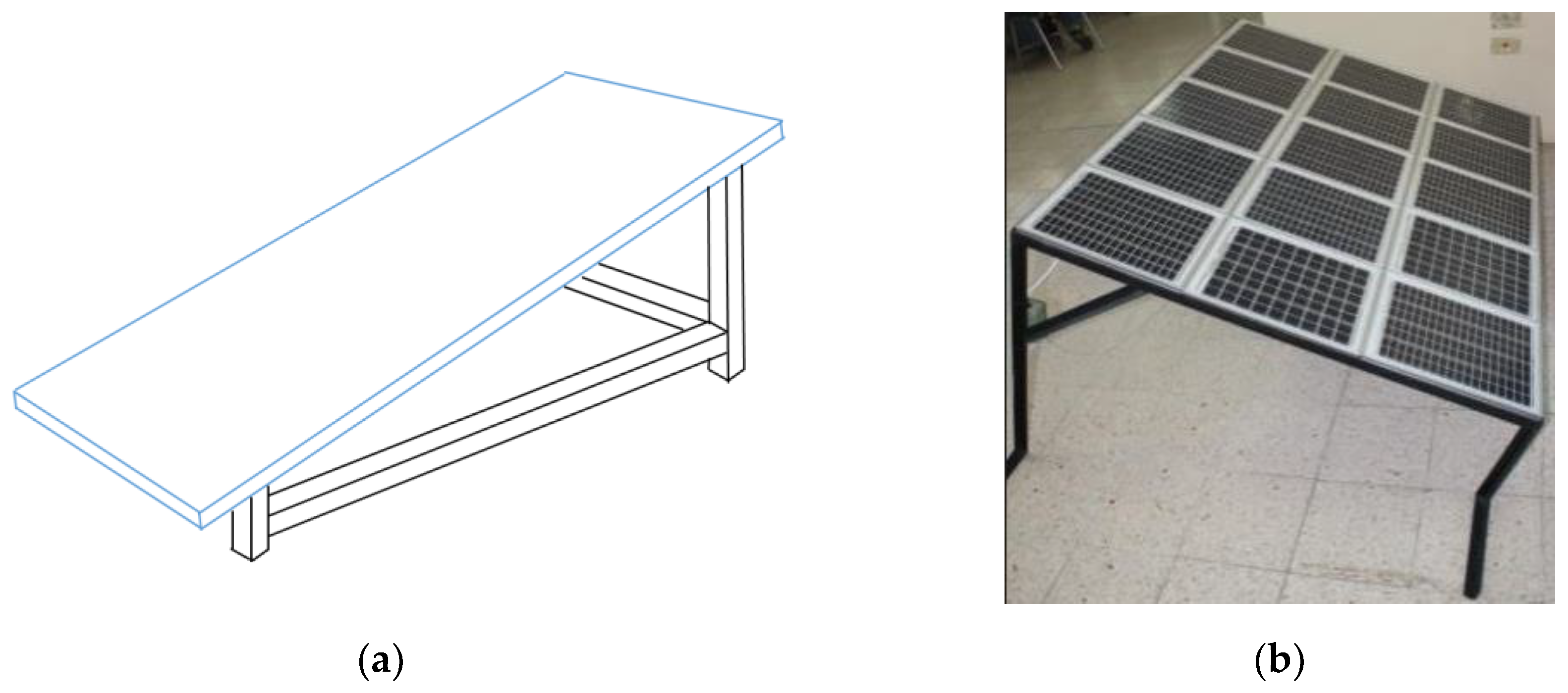
Figure 2.
Degrees of Freedom of the Solar Tracker.
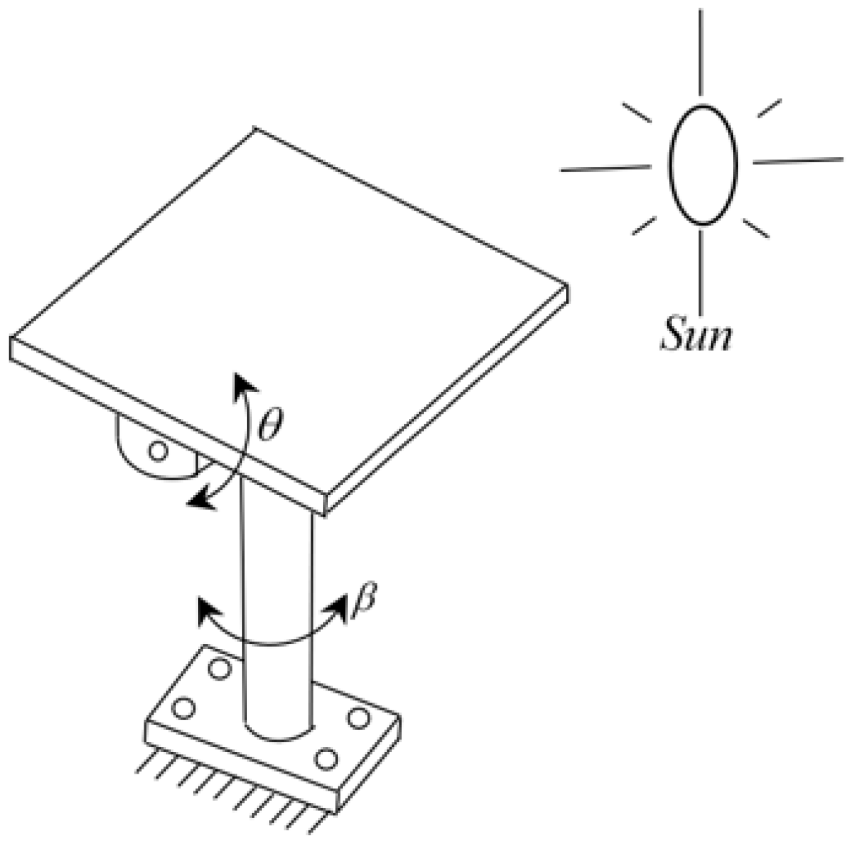
Figure 3.
(a) Commercial 4-bar mechanism. (b) Schematic diagram of the offset crank-rocker.
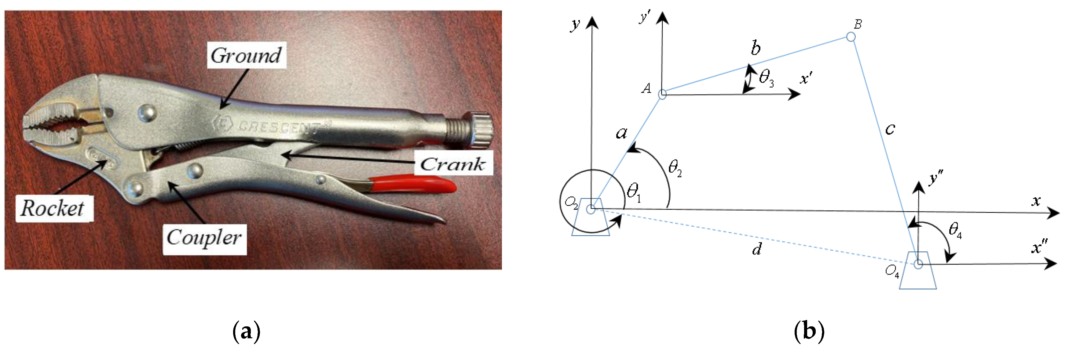
Figure 4.
Vector diagram of the offset crank-rocker mechanism.
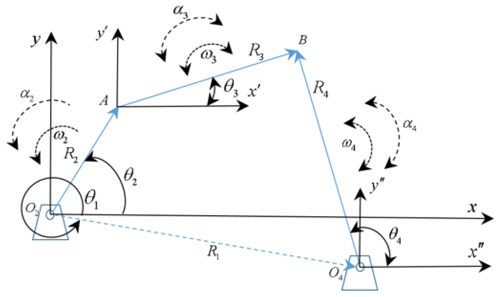
Figure 5.
(a) Commercial can crusher mechanism. (b) Schematic diagram of offset crank-slider.
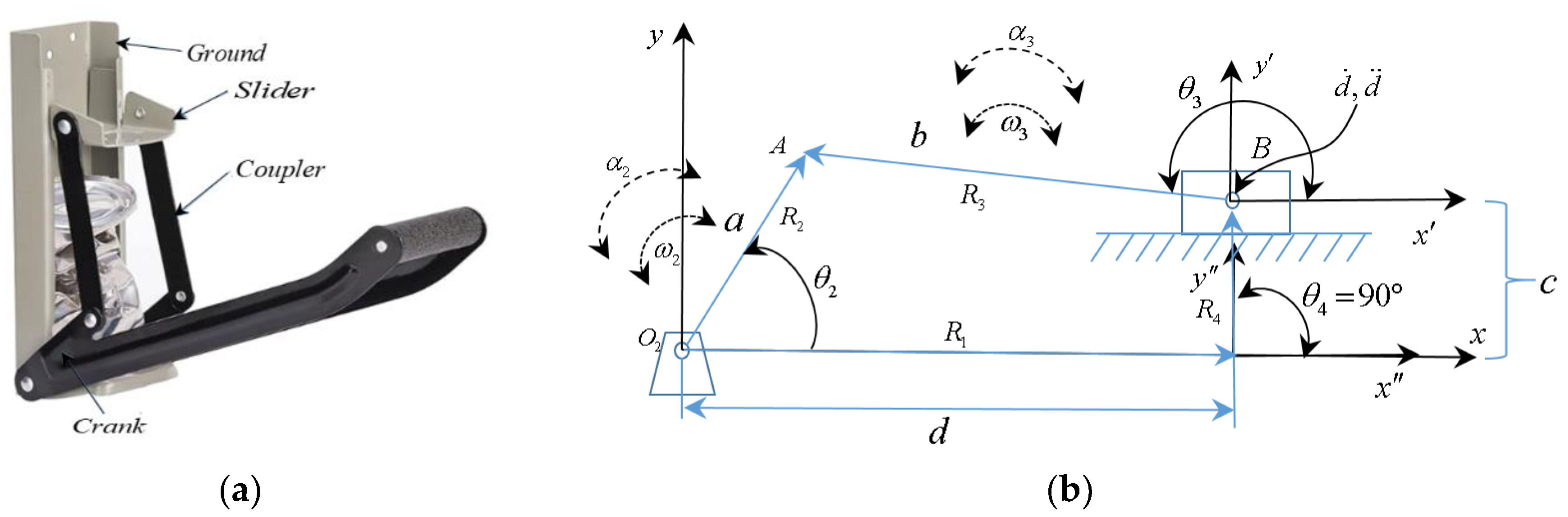
Figure 6.
Integration of a crank-rocker into a solar tracker.
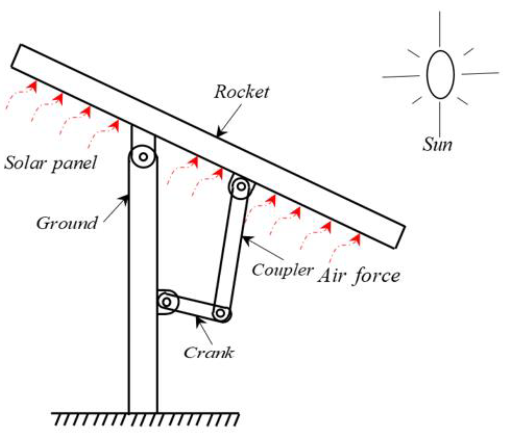
Figure 7.
(a) Geometric design proposal made in CAD SolidWorks 2019. (b) Functional 3-D printed model.
Figure 7.
(a) Geometric design proposal made in CAD SolidWorks 2019. (b) Functional 3-D printed model.
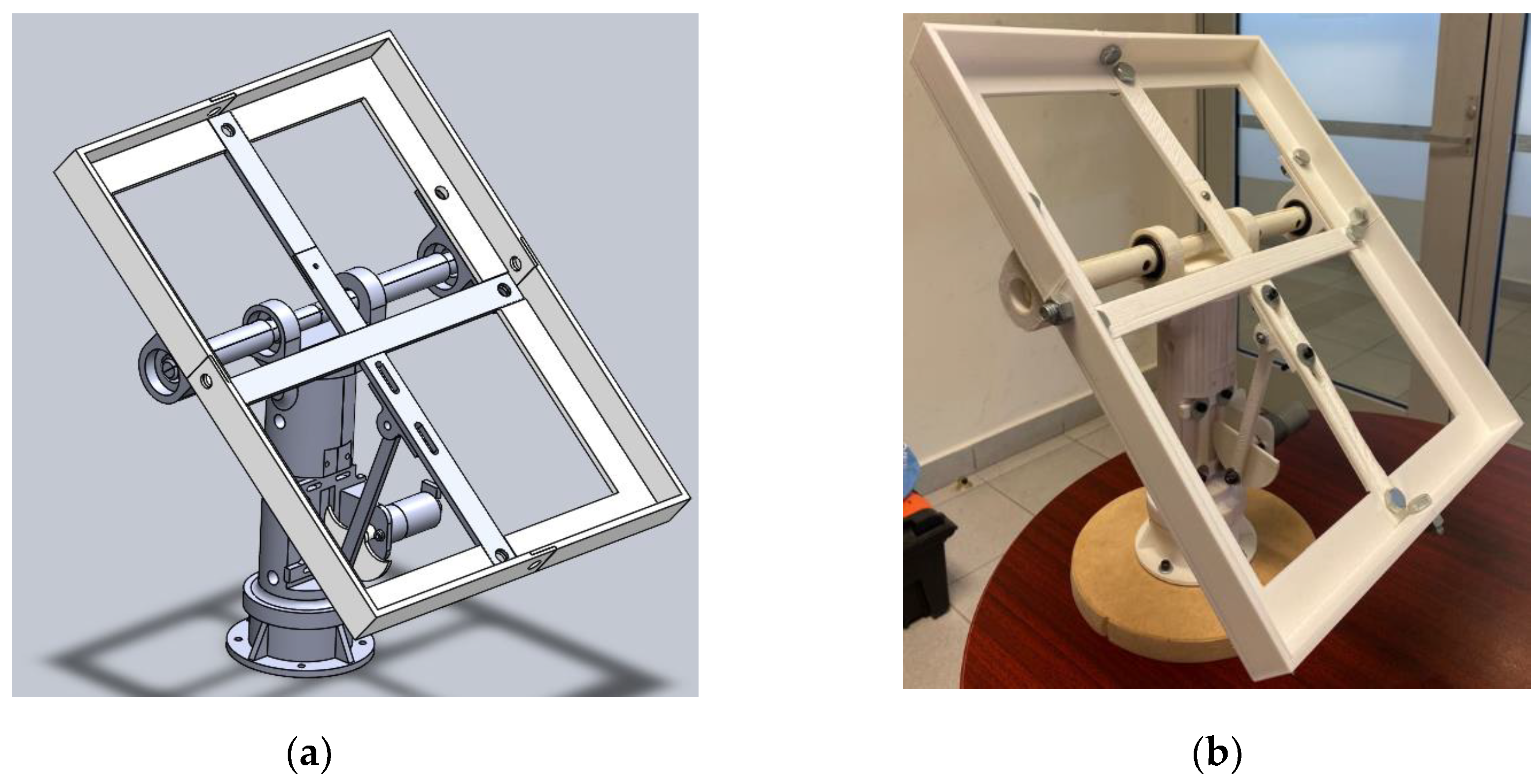
Figure 8.
Integration of a crank-slider into a solar tracker.
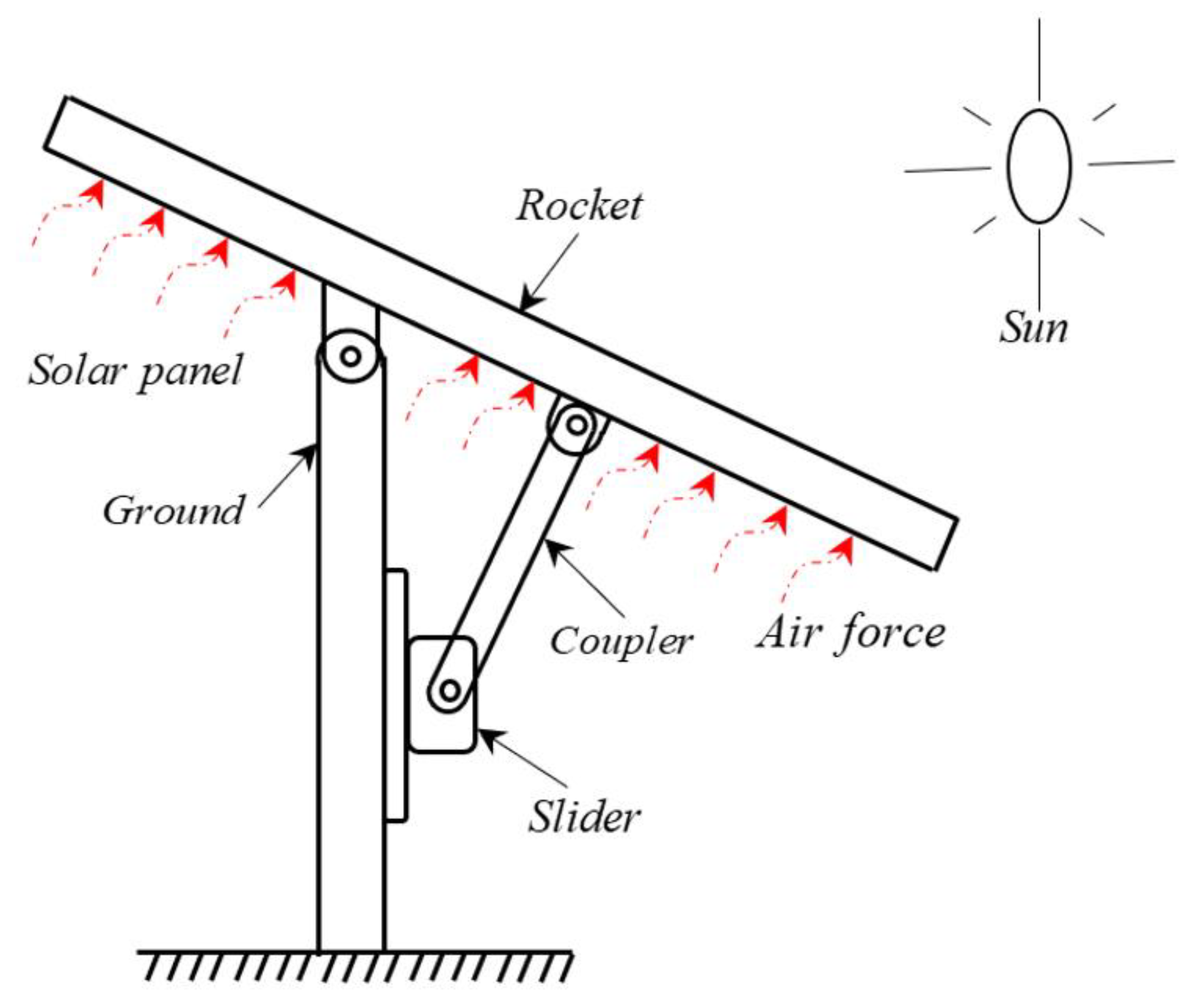
Figure 9.
(a) Proposed geometric design of the crank-slider in CAD SolidWorks 2019. (b) Functional 3D printed model of the crank-slider.
Figure 9.
(a) Proposed geometric design of the crank-slider in CAD SolidWorks 2019. (b) Functional 3D printed model of the crank-slider.
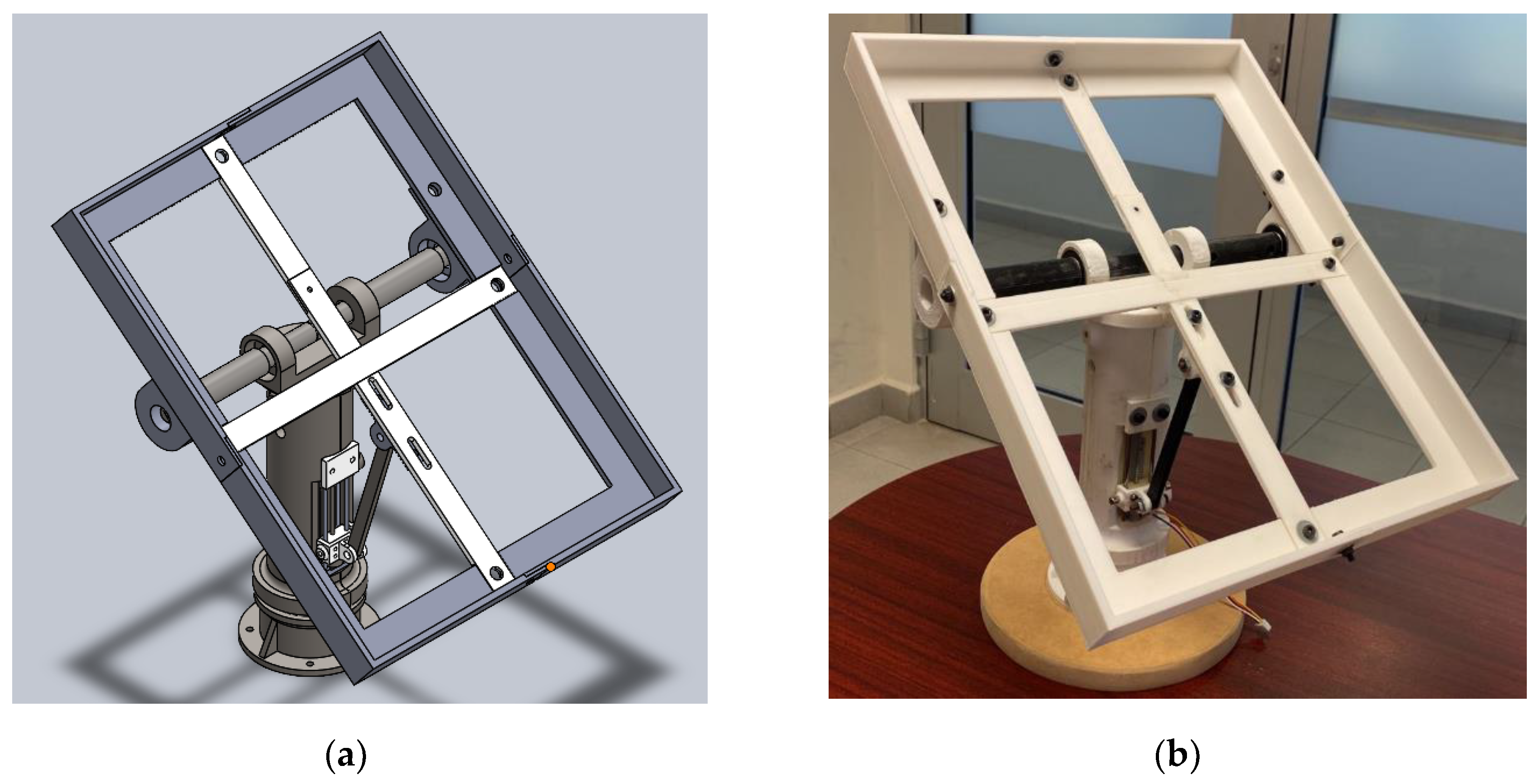
Figure 10.
Rocker arm position and acceleration pattern in its working range.
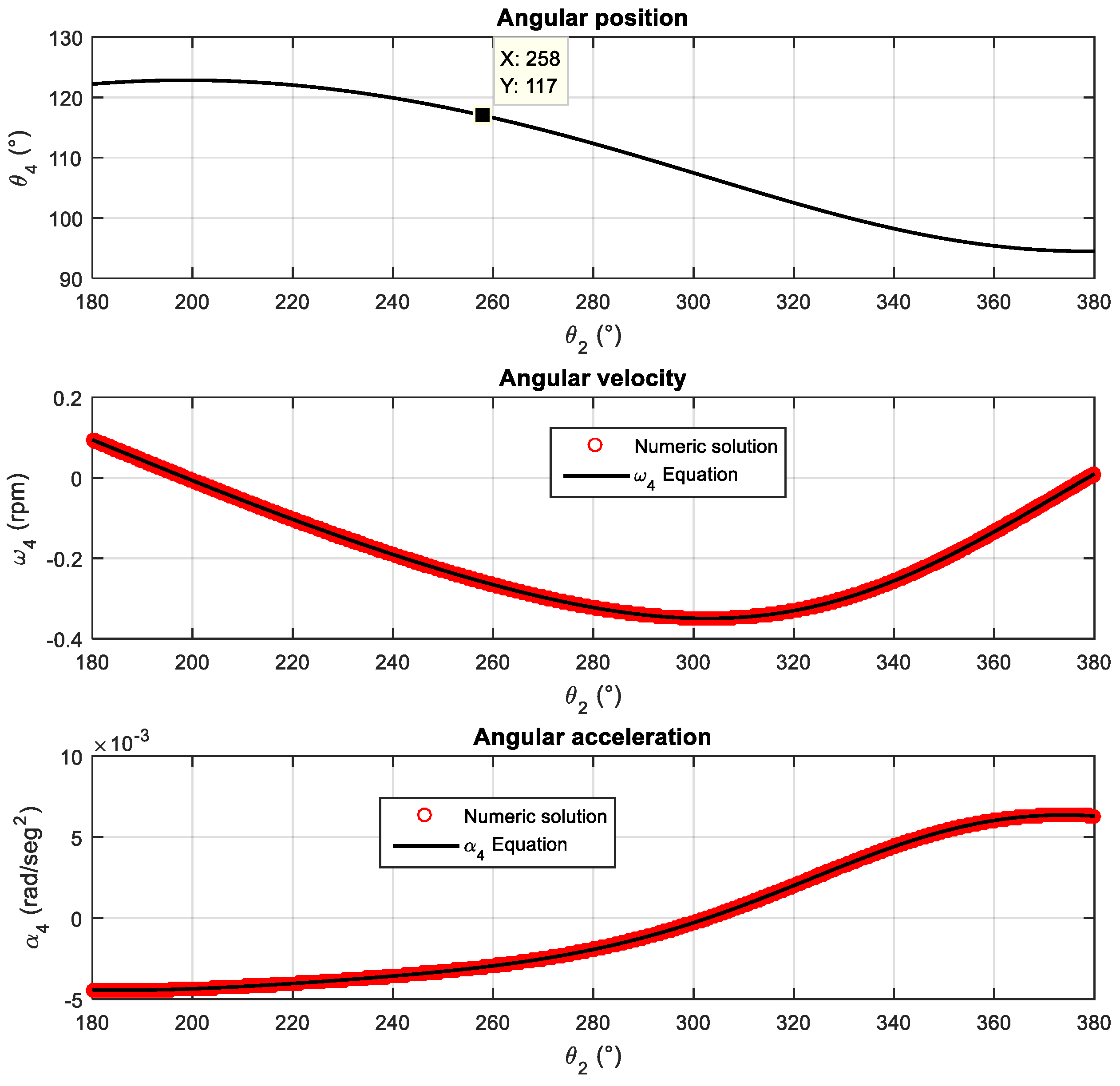
Figure 11.
(a) Characteristic pattern of the transmission angle in crank-rocker mechanisms. (b) Schematic diagram of a crank-rocker mechanism.
Figure 11.
(a) Characteristic pattern of the transmission angle in crank-rocker mechanisms. (b) Schematic diagram of a crank-rocker mechanism.
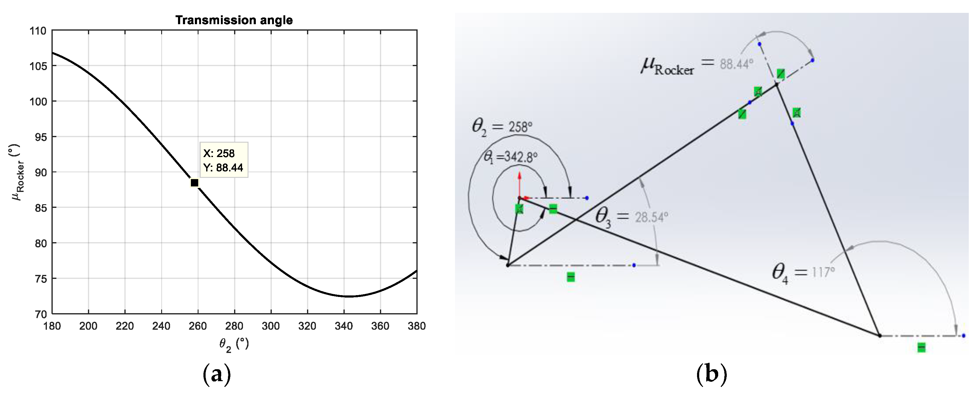
Figure 12.
Slider mechanism position and acceleration pattern in its working range.
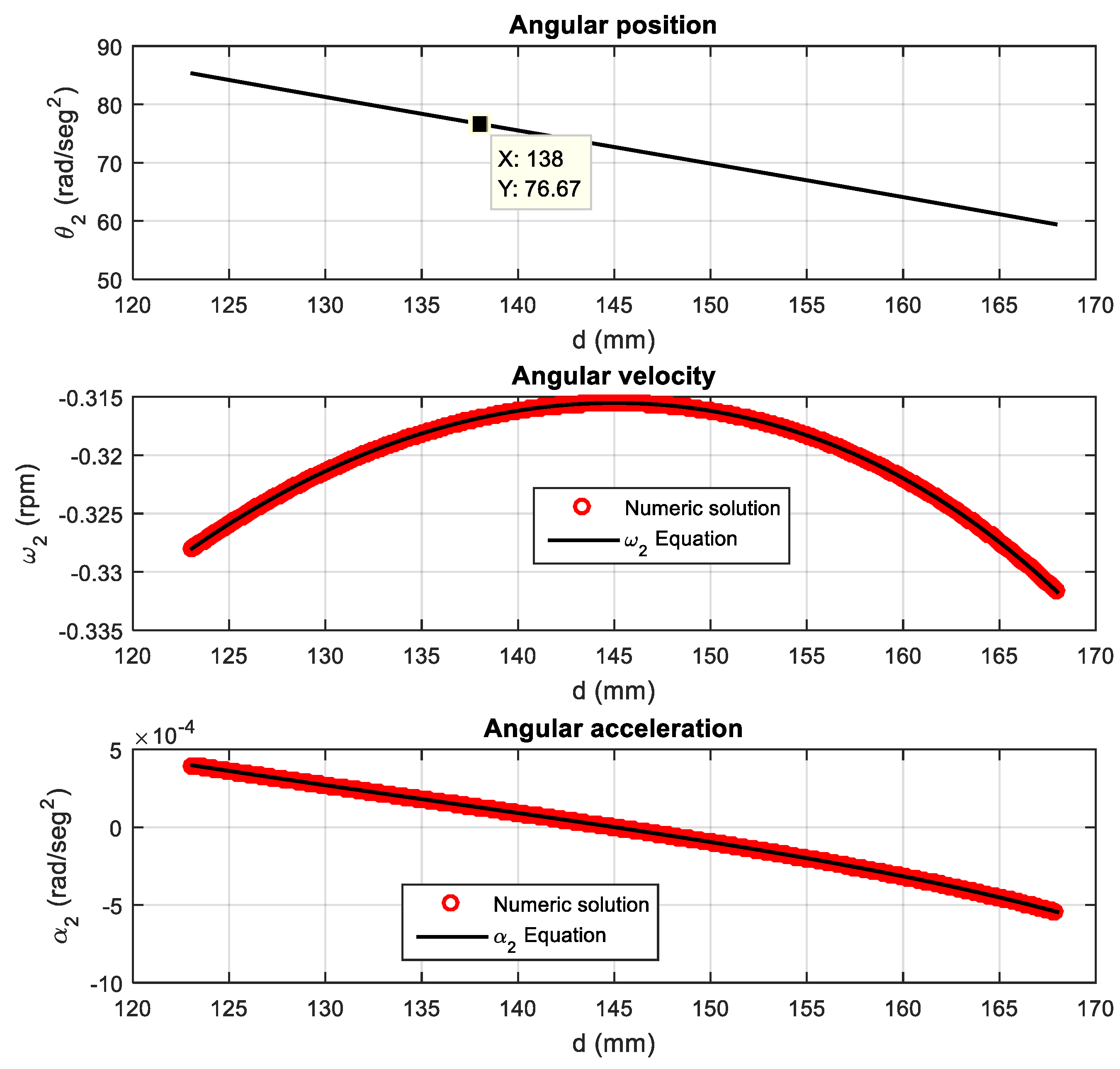
Figure 13.
(a) Characteristic pattern of the transmission angle in crank-slider mechanisms. (b) Schematic diagram of a crank-slider mechanism..
Figure 13.
(a) Characteristic pattern of the transmission angle in crank-slider mechanisms. (b) Schematic diagram of a crank-slider mechanism..
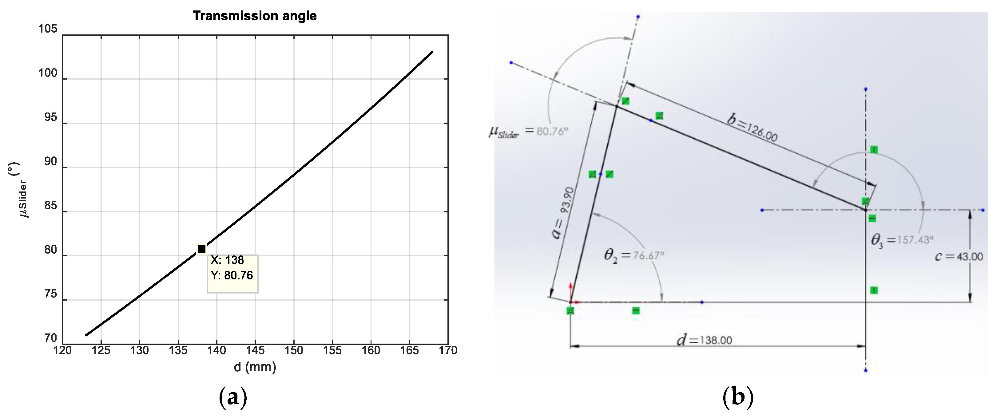

Table 1.
Numerical parameters for the scale crank-rocker mechanism.
| Description | Variable | Value |
|---|---|---|
| Crank | ||
| Coupler | ||
| Rocker | ||
| Ground | ||
| Ground angle | ||
| Working Range | ||
| Input Angular Velocity | ||
| Input Angular Acceleration |
Table 2.
Numerical parameters for the scale crank-slider mechanism.
| Description | Variable | Value |
|---|---|---|
| Crank | ||
| Eccentricity | ||
| Slider | ||
| Linear Slider Speed (manufacturer data) | ||
| Linear Slider Acceleration |
Disclaimer/Publisher’s Note: The statements, opinions and data contained in all publications are solely those of the individual author(s) and contributor(s) and not of MDPI and/or the editor(s). MDPI and/or the editor(s) disclaim responsibility for any injury to people or property resulting from any ideas, methods, instructions or products referred to in the content. |
© 2024 by the authors. Licensee MDPI, Basel, Switzerland. This article is an open access article distributed under the terms and conditions of the Creative Commons Attribution (CC BY) license (http://creativecommons.org/licenses/by/4.0/).
Copyright: This open access article is published under a Creative Commons CC BY 4.0 license, which permit the free download, distribution, and reuse, provided that the author and preprint are cited in any reuse.


