
Submitted:
01 July 2024
Posted:
01 July 2024
You are already at the latest version
Abstract
Due to the manufacturing process of Additive Manufacturing (AM) Parts the mechanical properties cannot be predicted. The scope of the present work is to propose a predictive tool for the mechanical properties of AM parts through the use of Adaptive Neuro-Fuzzy Inference System (ANFIS). The Adaptive Neuro-Fuzzy Inference System (ANFIS) combines neural networks with fuzzy logic to generate a mapping between the inputs and the output. Real data experiments from different AM technologies and materials compose the initial dataset so a detailed investigation is conducted to gain knowledge of how different parameters affect the UTS, the elongation and the Young modulus of each experiment. Experimental data were also use to train, check and verify the methodology. The method is tested for FFF technology, PLA material and 3 point bending stress, with interesting results.
Keywords:
Adaptive Neuro-Fuzzy Inference System
; ANFIS
; Additive Manufacturing
; AM
; 3D-Printing
; Mechanical Properties
; Predictive Model
; Bending
1. Introduction
Within the context of the fourth industrial revolution, several science sections merge with each other in order to lead the industry to new horizons. Fuzzy modelling, a tool which can impressively represent nonlinear relations between the parameters of system [1], along with an adaptive Artificial Neural Network (ANN) results in the Adaptive Neuro-Fuzzy Inference System (ANFIS). ANFIS can establish inputs-output systems based on both “if-then” rules and specified input-output data pairs [2]. This combination takes advantage of both tools in a single framework.
Additive Manufacturing is a rapidly expanding technology, applied to a wide range of industrial sectors, transforming design files to functional products –parts and assemblies as well. The main advantages of AM are the freedom of design, sustainability in energy and materials, the ability for complex structures to be manufactured and the affordability in fast prototyping. However, AM still faces low productivity and uncertainty of the parts, regarding its mechanical properties. The main reason is the multifactorial process parameters that influence the manufacturing procedure.
Several studies have been made to propose new methods and materials in AM, offering solutions and further development on the AM, as it is one of the four manufacturing pillars. In 1986 Charles Hull presented a new technology, which successive layers of materials are formed on top of each other creating three-dimensional parts. This new process was named stereolithography (SLA). Since then, new methods are being developed and novel materials are being applied allowing new applications and industry fields to merge in AM, continuously.
The seven major Additive Manufacturing categories, as classified and described by ASTM [20]:
- Binder Jetting: additive manufacturing process in which a liquid bonding agent is selectively deposited to join powder materials.
- Direct Energy Deposition: additive manufacturing process in which focused thermal energy is used to fuse materials by melting as they are being deposited.
- Material Extrusion: additive manufacturing process in which material is selectively dispensed through a nozzle or orifice, such as Fused Deposition Modelling (FDM) and Fused Filament Fabrication (FFF).
- Material Jetting: Additive manufacturing process in which droplets of build material are selectively deposited.
- Powder Bed Fusion: additive manufacturing process in which thermal energy selectively fuses regions of a powder bed, such as Selective Laser Sintering (SLS) and Selective Laser Melting (SLM).
- Sheet Lamination: additive manufacturing process in which sheets of material are bonded to form an object.
- VAT Photopolymerization: additive manufacturing proccess in which liquid photopolymer in a vat is selectively cured by light-activated polymerization, such as Stereolithography (SLA).
- The large variety of materials, used in AM, can be summoned [21] into four groups:
- Metals and Alloys in AM have been used for research, prototyping or advanced applications in aerospace, biomedical, defense and automotive industries, as their features are suitable for manufacturing complex geometries with special connections. The most common techniques for printing metals and alloys are PBF and DED. Stainless and tool steels, some aluminum alloys, titanium and its alloys, nickel-based alloys, some cobalt-based and magnesium alloys are materials which can be used in PBF-based processes as well.
- Polymers and Composites are the most common materials in AM and they are used along with SLA, SLS, FDM, 3D bio-printing and inkjet printing techniques. Such materials are being applied to aerospace, architectural, toy fabrication and medical fields.
- Ceramics is the answer to the challenge of the accuracy and the laminated appearance of the additively manufactured parts in tissue engineering (section of the biomedical engineering). The main methods in which ceramics are used are inkjet (suspension), PBF, paste extrusion and SLA.
- Concrete has been added to the list of the AM materials. Material extrusion process by using large nozzles and high pressure for the extruded material. The size of the constructions and the required early strength of concrete to support successive layers are the challenge of this material.
New Additive Manufacturing (AM) technologies are continually being developed and the variety of materials utilized in these processes is expanding rapidly. Moreover, AM, also known as 3D-Printing, is experiencing significant growth rapidly due to its facilitation capabilities and plays a pivotal role in industries, such as aerospace, oil and gas, automotive, energy, medical, tool and die, and other consumer goods [3]. As Artificial Intelligence (AI) tools can be applied to control the factors that affect the anisotropic mechanical properties of the materials [4]-[5], this study will explore the convergence of AM and ANFIS. The aim is to develop a tool that can predict the mechanical properties of specimens taking into consideration most of the setting parameters during the AM process, thereby enhancing the efficiency of AM applications.
Although Additive Manufacture is gaining popularity due to its reduced product cycle time and the lack of need for expensive tools, the commercialization of this technology is still limited because of several shortcomings. One of the most significant issues is the difficulty in determining the strength of the parts, which arises from the anisotropic and heterogeneous microstructure of the fabricated parts. The most critical material characteristics are the mechanical properties, as they determine the product’s ability to meet the designed requirements. These properties, which include stress, Young's modulus, and elongation, depend on various process parameters, such as the applied AM method, material, infill pattern & percentage, layer thickness, the existence of wall and its thickness, temperature, building orientation, curing conditions etc.
Previous studies ([6] - [18]) on the same subject usually focus on the study of a limited number of the most significant parameters, within the strict boundaries of the conducted experiments, using several experimental, numerical and statistic methods.
This research is triggered by the need to develop a unified tool for predicting the mechanical properties of AM parts, adaptable to any AM technology and material, while accounting for the various process parameters that impact the final product. The mechanical properties to be approached are Maximum Stress, Young Modulus and Elongation Percentage.
With the rapid invention of new AM technologies and the expanding range of materials used, there is a focus on a wide array of applications. Additionally, novel techniques are being continuously applied. Therefore, Artificial Intelligence (AI) can be employed to control the factors that affect the mechanical properties of the materials ([4]).
This study examines the synergy between Additive Manufacturing (AM) and Artificial Intelligence (AI) to develop an AI tool aimed at enhancing the understanding and efficient use of materials in AM. This tool will be used to predict the mechanical properties of the specimens, considering the majority of setting parameters during the AM process, thereby benefiting research and practical applications.
2. The Adaptive Neuro-Fuzzy Inference System (ANFIS)
Modeling of processes and system identification using input-output data has attracted many research efforts. The main components of soft computing, such as fuzzy logic and neural networks have shown great ability in solving complex non-linear system identification and control problems. The Adaptive Neuro-Fuzzy Inference System (ANFIS) model is a hybrid predictive model that combines the learning capabilities of Artificial Neural Networks (ANNs) with the reasoning capabilities of fuzzy logic. ANFIS uses input–output sets and a series of IF–THEN fuzzy rules to incorporate the human-like reasoning style of fuzzy inference systems (FIS). The ANFIS model is especially effective in a variety of engineering applications when data is inconsistent or nonlinear, where conventional methods fail or are too complicated to employ.
A typical ANFIS structure consists of five layers, wherein each layer is constructed by several nodes. The outputs of the previous layer are used as input nodes for the current layer. Considering a first-order Sugeno fuzzy model with two inputs x and y and one output f, a typical rule set with two fuzzy if–then rules can be expressed as
- Rule 1: If (x is A1) and (y is B1) then (f1 = p1x + q1y + r1)
- Rule 2: If (x is A2) and (y is B2) then (f2 = p2x + q2y + r2)
Where x, y are inputs, Ai, Bi are membership functions and pi, qi, ri are consequent parameters and i is the node number. The corresponding equivalent ANFIS architecture is shown in Figure 1. The entire system architecture consists of five layers, namely, the fuzzy layer (Layer 1), product layer (Layer 2), normalized layer (Layer 3), consequence layer (Layer 4) and total output layer (Layer 5). The number of nodes in other layers (layer 2–4) relates to the number of fuzzy rules (R).
The basic idea behind using neuro-adaptive learning techniques is that it is very simple and allows implementation of multi-input–single-output first order Sugeno type FIS. This technique provides a method for the fuzzy modeling procedure to learn information about a data set, in order to compute the membership function parameters that best allow the associated fuzzy inference system to track the given input/output data. This learning approach takes place prior to the operation of the control system. The ANFIS methodology can be decomposed into four steps:
Step 1: A set of input–output data, to be used as training data, is obtained from the sewing process. Another optional data set can be used as test data after training.
Step 2: The initial Sugeno-type FIS structure, regarding antecedent membership functions, number of rules and consequence parameters is created.
Step 3: The learning process is carried out using the training data to adjust the membership functions, to create the interference rules and to determine the consequent parameters.
Step 4: The model is validated using the testing data, which have not been used during the training. The objective of this validation is to validate its generalization capability.
3. Experimental Results and Validation
Through literature review and experiments [9], many factors that influence the mechanical properties of the AM specimens were gathered. By the use of Taguchi methodology and sensitivity analysis these factors were classified according to their impact on the mechanical properties of the specimens. These factors and their values were selected as input to the ANFIS Model. Bending, Tension and Torsion experiments were conducted on various materials and the use of many AM technologies, such as SLA, FFF, SLS etc. All experiments were conducted according to ASTM standards such as ASTM D638, D695, D7791, D790 and D5279.
3.1. Gathering Experimental Data
Some of the specimens used for bending test are visually presented in Figure 2. Figure 3 illustrates the bending test (a) conducted according to ASTM D790 and the specimen after the test (b) according to ASTM D790. All data used for the model, were from experiments conducted at the strength of materials Laboratory, Mechanical Engineering Department, University of West Attica.
The constant settings of the printing devices during the process are recorded along with the values of the examined parameters in order to describe the conditions in total. Figure 4 is indicatively presented to record the information of the experiments.
A dataset is created to host all the experimental data. Each column represents one input parameter. Twenty one parameters are used in total; namely, (1) AM Technology, (21) Tension Type, (3) Material, (4) Infill Pattern, (5) Infill Percentage, (6) Layer Thickness, (7) Wall Thickness, (8) Speed, (9) Extruder Temperature, (10) Laser Power Ratio, (11) Bed Temperature, (12) Position on Printer Bed, (13) Incline against Printer Bed, (14) Twist around Axis of Centre of Gravity, (15) Raster Angle, (16) Layers for Alternating Raster Angle, (17) Percentage of First Material, (18) Curing Time, (19) Curing Power, (20) Layer Composition and (21) Cross Section. The conditions of each specimen are recorded in one line of the dataset. Figure 2 shows a portion of the dataset where both the examined and the constant conditions are recorded. Figure 5(a) and Figure 5(b) illustrate how the position of the specimens on the printer table are codified.
3.2. The Proposed ANFIS Model
Considering that ANFIS models have only one output, three similar models (one for each output property) are developed. In this work, the model for “Maximum Stress” is presented, while remarkable facts for the other two models are demonstrated. Using a short program code in MATLAB, the three individual arrays are randomly split into training and checking data.
Firstly, a new Neuro-Fuzzy system is created using the aforementioned inputs-output pair of data. The Fuzzy Inference System (FIS) is generated following the Subtractive Clustering method [19], as suggested for systems with more than 6 input parameters. Figure 6 shows the scattering of the output values, while Figure 7 shows the training process of the system. The FIS test against the training data (Figure 8) revealed a well-trained system, but the test against the checking data (Figure 9) showed low performance. The Root Mean Square Error (RMSE) of the model equals to 9.17, 20% within the range of the outputs, caused probably by the high number of the examined factors compared to the low number of the entries. Regarding the RMSE for Young Modulus and the Elongation Percentage, the values for the index error were correspondingly high (41% and 51% within the range of the data for each one, respectively).
3.3. The Evaluation Model
During the evaluation of the results of the ANFIS, it is observed that more data entries are necessary in order that the system reveals the ability to predict accurate results. Thus, it is decided a more adaptable model to be created and tested in order to evaluate the appropriateness of the method. A new 9-parameter “evaluating” model is developed. For that purpose, the experiments are checked thoroughly and only areas with satisfactory information are preserved. Twelve of the input parameters are either removed or filtered. The new dataset refers only to PLA material, fabricated with Fused Filament Fabrication (FFF) technology, while the specimens will be tested in bending only. The input parameters in it are Infill Pattern, Infill Percentage, Layer Thickness, Speed, Extruder Temperature, Bed Temperature, Position on Printer Bed, Incline against Printer Bed and Raster Angle. Table 3 shows a portion of the dataset for this model

Table 1.
Portion of the datasheet for the evaluation model.
| Infill Pattern | Infill (%) | Layer Thickness (mm) | Speed (mm/s) | Temperature (oC) |
|---|---|---|---|---|
| 2 | 50 | 0.1 | 50 | 200 |
| 2 | 75 | 0.1 | 50 | 200 |
| 3 | 100 | 0.1 | 50 | 200 |
| 2 | 75 | 0.2 | 50 | 200 |
| 2 | 100 | 0.2 | 50 | 200 |
| 3 | 50 | 0.2 | 50 | 200 |
| 2 | 100 | 0.3 | 50 | 200 |
| 2 | 50 | 0.3 | 50 | 200 |
| 3 | 75 | 0.3 | 50 | 200 |
Table 2.
Portion of the datasheet for the evaluation model.
| Bed Temperature (°C) | Position on Bed | Twist angle (°) | Inclination (°) |
|---|---|---|---|
| 60 | 1 | 1 | 5 |
| 60 | 3 | 1 | 5 |
| 60 | 5 | 1 | 7 |
| 60 | 5 | 1 | 5 |
| 60 | 1 | 1 | 5 |
| 60 | 3 | 1 | 7 |
| 60 | 3 | 1 | 5 |
| 60 | 5 | 1 | 5 |
| 60 | 1 | 1 | 7 |
Further examination of the new dataset revealed three areas where the responses vary from low to quite accurate. Taking this into account, more investigation on the settings of the FIS is conducted. Figure 10 illustrates the five processing layers and the connections between them within the structure of the ANFIS model. The dataset is split into a training-checking pair of data, using the program code, and the pair is loaded in a new ANFIS (Figure 11). The training process depicted in Figure 12 declares that due to the limited entries, the system achieves the best convergence since the first epoch. Finally, Figure 13 represents the error resulted in the test against the checking data. It equals to 1.17, which compared to the range of the checking outputs equals to 9.75%.
Similarly, two predicting ANFIS’s αre developed for the Young Modulus and the Elongation Percentage of the subject dataset. For both models the training error equals to zero. Figure 14 and Figure 15 represent the checking data for the two cases, respectively. Regarding the Young Modulus, the error equals to 3049 which reflects the 40% of the range of the data. However, the error on the Elongation Percentage equals to 2.21, being reduced to 20% within the range of the data.
4. Analysis of Model Performance
The ANFIS initially developed for 21 outputs showed inadequate performance in achieving satisfactory results for the analyzed properties of the specimens. Although the training process showed excellent recognition of the correlations of the 3D-Printing parameters with the output values, the test against the checking data proved that the entries in the dataset are few to support the method. The resulted RMSE against checking data is 20%, 41% and 51% within the range of data for Maximum Stress, Young Modulus and Elongation Percentage, respectively.
The limited ANFIS model, consisting of nine inputs, appeared improved RMSE for Max Stress and Elongation Percentage, equal to 9.75% and 20%, respectively. The fact that the index for the Young Modulus remained at the level of 40% seems to be illusory, as there is one value the deviation of which is about 8000 units and that shoots up the RMSE. It could be an evidence that the number of the available data were not adequate.
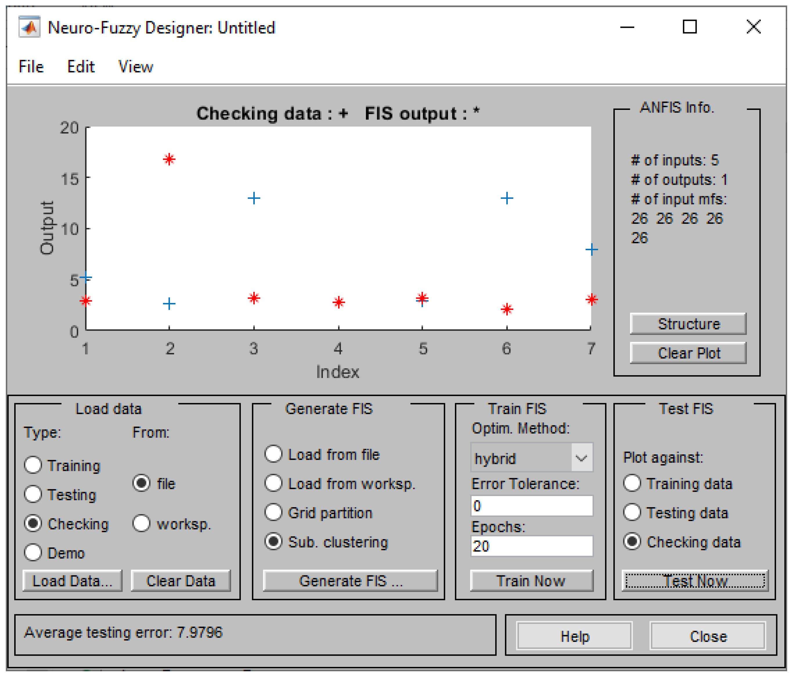
Additionally, a diminished model is created to check whether a more limited model would give better results. Five inputs and one output composed this set. The input parameters in this model were Infill Percentage, Layer Thickness, Speed, Extruder Temperature and Raster Angle. Although the system was trained correctly (Figure 16), the high RMSE (Figure 17) during the test of the checking data proved that the information that were ignored, by removing some inputs of minor significance, led the system to fail.
5. Conclusions
This work presents a novel approach for predicting the mechanical properties of AM specimens. The main focus of this research aimed at establishing a novel, flexible method for predicting the mechanical properties of Additively Manufactured parts through Artificial Neural Networks and Fuzzy Logic.
In line with the objective of optimizing the AM fabrication process, the majority of the relevant studies typically focus and examine a limited number of parameters within the strict boundaries of the experiments. The innovative aspect of this research is the development of a predictive model capable of adapting to any AM technology and material, while considering the various process parameters that affect the Maximum Stress, Young Modulus and Elongation Percentage of the final product.
The results of the developed systems revealed the potentiality of the method to provide successful predictions, highlighting the necessity for more input data. This would enable an accurate initial estimation of the applied AM process (including AM technology, material, structure settings and process parameters), thereby avoiding the waste of crucial resources.
Despite the potential of this novel approach, it is clear that further experiments are necessary to enhance the model. Future experiments will enrich the dataset with results from different AM technologies, materials and experimental studies.
Given ANFIS's proven capability to identify nonlinear relationships in the field of mechanical properties, it can be applied to other areas of research. For example, examining the surface quality of AM parts using ANFIS, while integrating the knowledge gained from this study, would be particularly interesting.
Author Contributions
Conceptualization, V.D.S and P.Z.; methodology, V.D.S, P.Z. and A.T.; P.Z. and A.T.; validation, V.Δ.S., P.Z. and A.T.; formal analysis, A.T., P.Z. and V.D.S.; investigation, A.T., V.D.S. and P.Z.; resources, V.D.S. and A.T.; data curation, V.D.S. and A.T.; writing—original draft preparation, A.T., V.D.S, and P.Z.; writing—review and editing, V.D.S., A.T., P.Z. and C.S.; visualization, A.T.; supervision, C.S.; funding acquisition, C.S.. All authors have read and agreed to the published version of the manuscript.
Funding
This research received no external funding.
Institutional Review Board Statement
Not applicable.
Informed Consent Statement
Not applicable.
Data Availability Statement
Data are contained within the article.
Conflicts of Interest
The authors declare no conflicts of interest.
References
- Takagi, T. & Sugeno, M.. Fuzzy identification of systems and its applications to modeling and control. IEEE transactions on systems, man, and cybernetics 1985, SMC-15, 116–132.
- Jang, J.-S. ANFIS: adaptive-network-based fuzzy inference system. IEEE transactions on systems, man, and cybernetics 1993, 23, 665–685. [Google Scholar] [CrossRef]
- Callı, M. , Albak, E.I. and Ozturk, F..Prediction and Optimization of the Design and Process Parameters of a Hybrid DED Product Using Artificial Intelligence. Applied Sciences 2022, 12, 5027. [Google Scholar] [CrossRef]
- Ali, M. H, Batai, S. and Sarbassov, D.. 3D printing: a critical review of current development and future prospects. Rapid prototyping journal 2019, 25, 1108–1126. [Google Scholar] [CrossRef]
- Divjak, A. , Modrić, D., Kovačić, I. & Cviljušac, V.. Anisotropic Mechanical Properties of Materials in Stereolithographic Additive Manufacturing. Technical Gazette 2020, 27, 1748–1753. [Google Scholar]
- Khorasani, A. , Gibson, I., Awan, U. S., & Ghaderi, A.. The effect of SLM process parameters on density, hardness, tensile strength and surface quality of Ti-6Al-4V. Additive manufacturing 2019, 25, 176–186. [Google Scholar]
- Ramesh, M. & Panneerselvam, K. Mechanical investigation and optimization of parameter selection for Nylon material processed by FDM. Materials Today: Proceedings 2021, 46, 9303–9307. [Google Scholar]
- Abouelmajd, M. , Bahlaoui, A., Arroub, I., Zemzami, M., Hmina, N., Lagache, M., & Belhouideg, S.. Experimental analysis and optimization of mechanical properties of FDM-processed polylactic acid using Taguchi design of experiment. International journal for simulation and multidisciplinary design optimization 2021, 12, 30. [Google Scholar]
- Sagias, V. D. , Giannakopoulos, K. I., & Stergiou, C.. Mechanical properties of 3D printed polymer specimens. Procedia Structural Integrity 2018, 10, 85–90. [Google Scholar]
- Polyzos, E. , Katalagarianakis, A., Polyzos, D., Van Hemelrijck, D., & Pyl, L. A multi-scale analytical methodology for the prediction of mechanical properties of 3D-printed materials with continuous fibres. Additive Manufacturing 2020, 36, 101394. [Google Scholar]
- Kumar Mishra, P. & Senthil, P.. Prediction of in-plane stiffness of multi-material 3D printed laminate parts fabricated by FDM process using CLT and its mechanical behaviour under tensile load. Materials today communications 2020, 23, 100955. [Google Scholar]
- Yadav, D. , Chhabra, D., Gupta, R. K., Phogat, A., & Ahlawat, A.. Modeling and analysis of significant process parameters of FDM 3D printer using ANFIS. Materials Today: Proceedings 2020, 21, 1592–1604. [Google Scholar]
- Mehrpouya, M. , Gisario, A., Rahimzadeh, A., Nematollahi, M., Baghbaderani, K. S., & Elahinia, M.. A prediction model for finding the optimal laser parameters in additive manufacturing of NiTi shape memory alloy. International journal of advanced manufacturing technology 2019, 105, 4691–4699. [Google Scholar]
- Mohamed, O. A. & Xu, W.. Comment about lack of sufficient data on ‘A prediction model for finding the optimal laser parameters in additive manufacturing of NiTi shape memory alloy’ by Mehrpouya, M., Gisario, A., Rahimzadeh, A., Nematollahi, M., Baghbaderani, K. S., & Elahinia, M.. The International Journal of Advanced Manufacturing Technology 2019, 105, 4691– 4699. Progress in Additive Manufacturing 2021, 7, 435–442. [Google Scholar]
- Dhar, A. R. , Gupta, D., & Roy, S. S..Development of a bi- directional multi- input- multioutput predictive model for the fused deposition modelling process using co-active adaptive neurofuzzy inference system, IOP Conference Series. Materials Science and Engineering 2021, 1136, 12007. [Google Scholar]
- Abate, K. M. , Nazir, A., & Jeng, J.-Y.. Design, optimization, and selective laser melting of vin tiles cellular structure-based hip implant. International journal of advanced manufacturing technology 2021, 112, 2037–2050. [Google Scholar]
- Hu, Z. , & Mahadevan, S. Uncertainty quantification in prediction of material properties during additive manufacturing. Scripta Materialia 2019, 135, 135–140. [Google Scholar]
- Dev, S. & Srivastava, R. Experimental investigation and optimization of FDM process parameters for material and mechanical strength. Materials Today: Proceedings 2017, 26, 1995–1999. [Google Scholar]
- Srisaeng, P. & Baxter, G.. Predicting Australia’s Domestic Airline Passenger Demand using an Anfis Approach. Transport and telecommunication 2022, 23, 151–159. [Google Scholar]
- ASTM International, Standard Terminology for Additive Manufacturing Technologies. ASTM F2792-12 2012, 1, 1.
- Ngo, T.D. , Kashani, A., Imbalzano, G., Nguyen, K.T., Hui, D.Additive manufacturing (3D printing): A review of materials, methods, applications and challenges. Composites. Part B, Engineering 2018, 143, 172–196. [Google Scholar] [CrossRef]
Figure 1.
ANFIS Architecture.
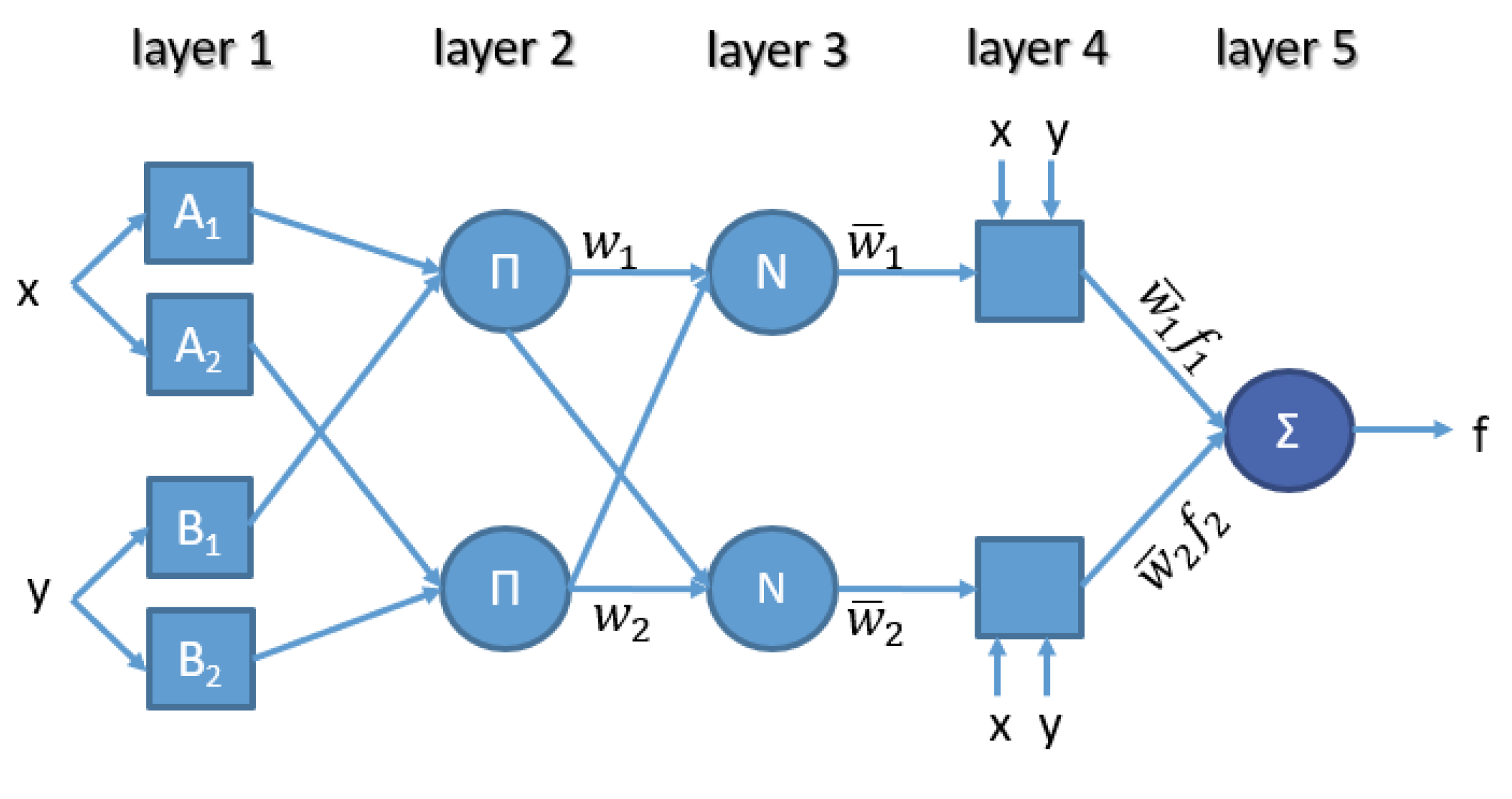
Figure 2.
One group of specimens used for bending.
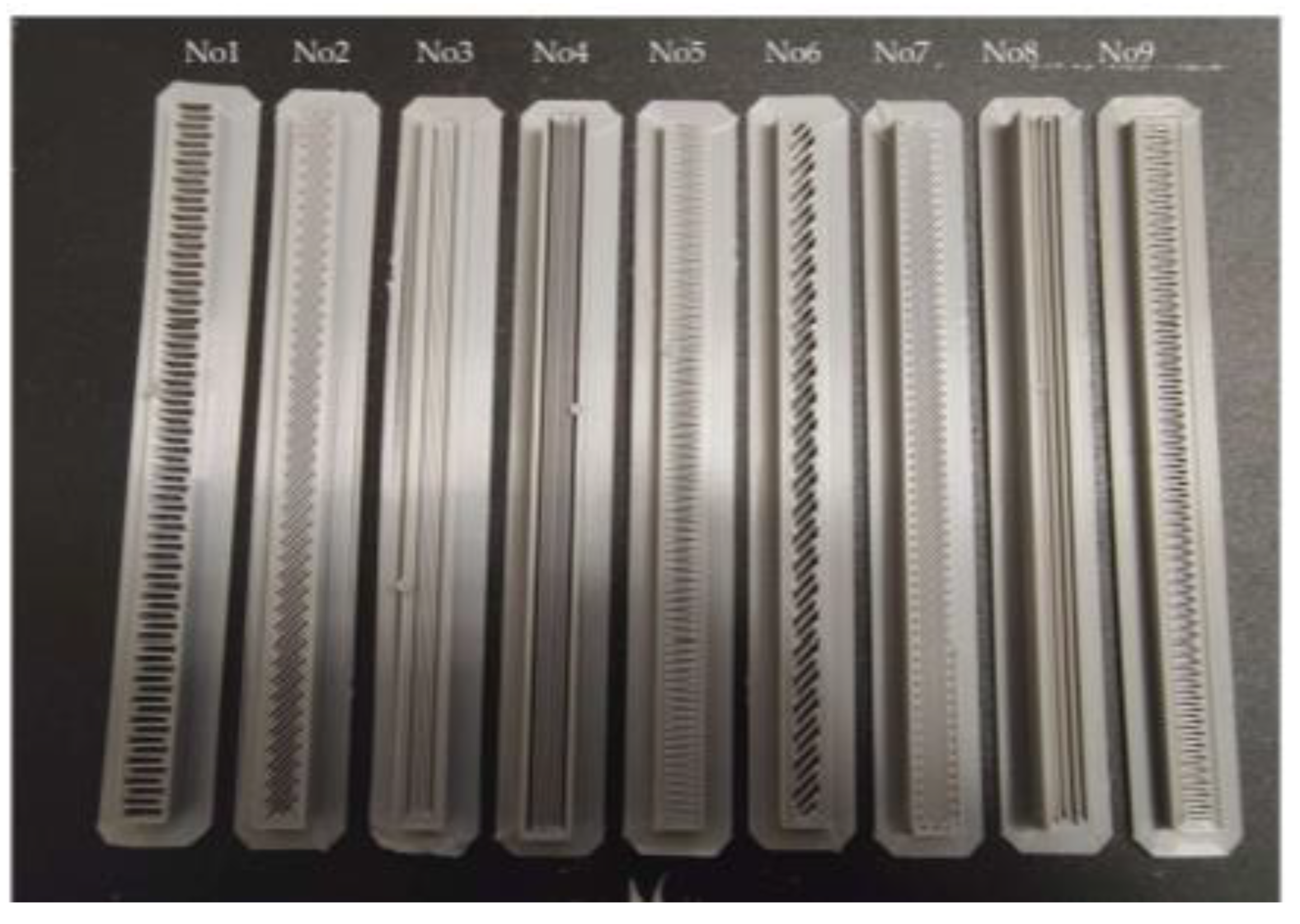
Figure 3.
Bending Test on PLA material manufactured by FFF.: (a) The Bending test; (b) Bending specimen after the test.
Figure 3.
Bending Test on PLA material manufactured by FFF.: (a) The Bending test; (b) Bending specimen after the test.
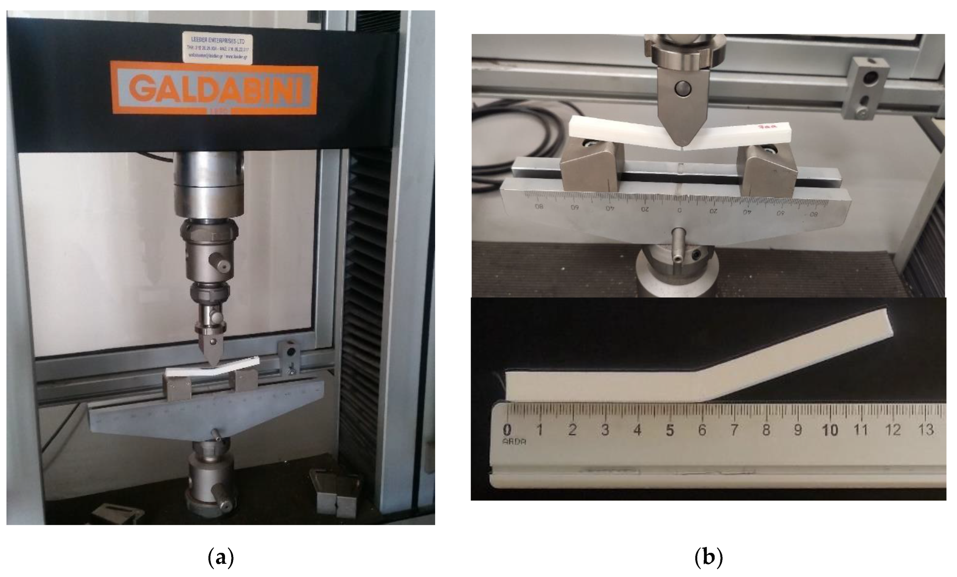
Figure 4.
The process parameters for each experiment.
Figure 5.
Schematic representation of selected parameters: (a) Input 12, Position on Printer Bed; (b) Input 13, Incline against Printer Bed.
Figure 5.
Schematic representation of selected parameters: (a) Input 12, Position on Printer Bed; (b) Input 13, Incline against Printer Bed.
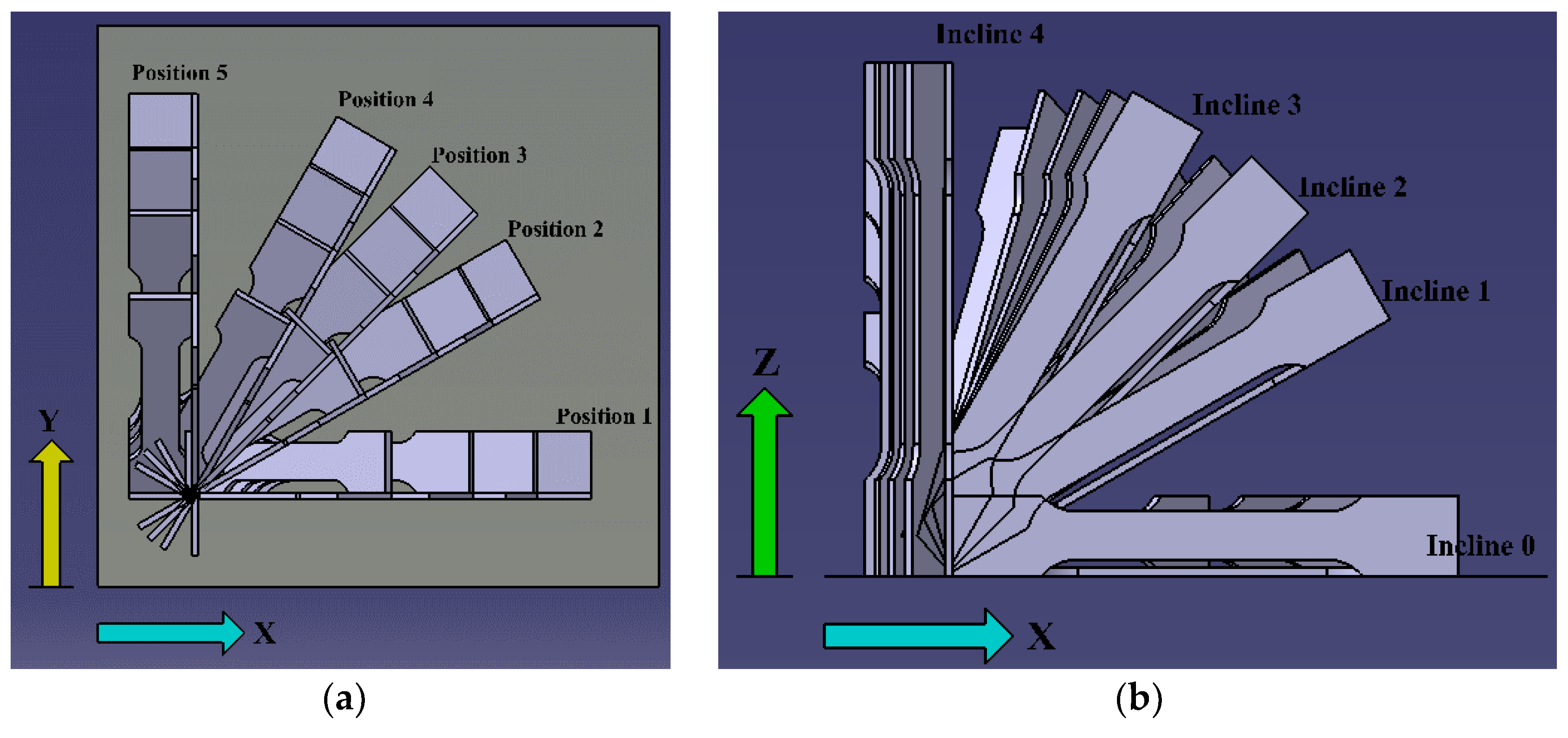
Figure 6.
Input 13, Data for 21 input variables.
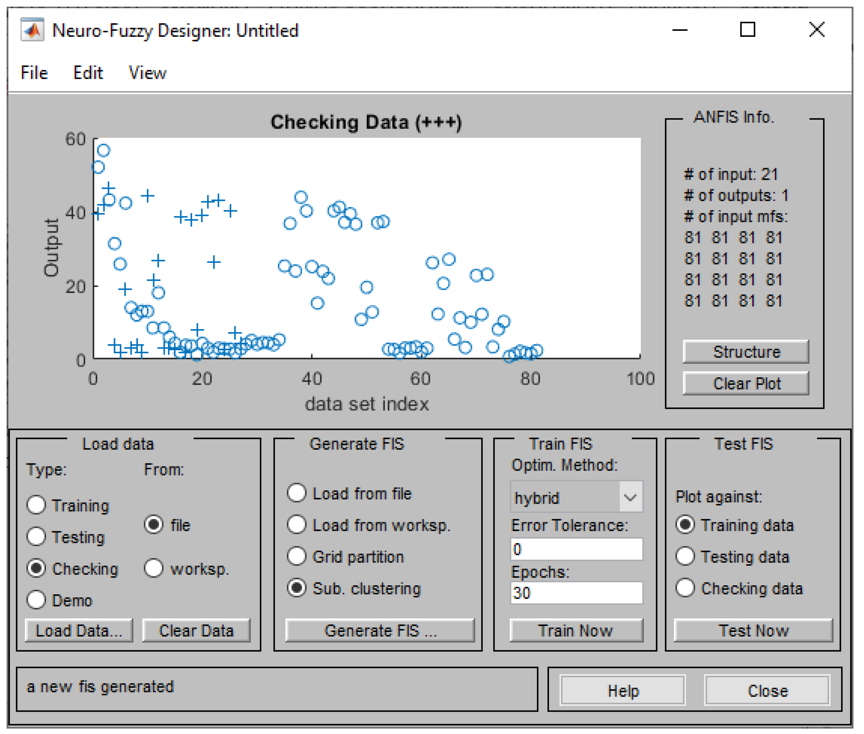
Figure 7.
Training process of the ANFIS.
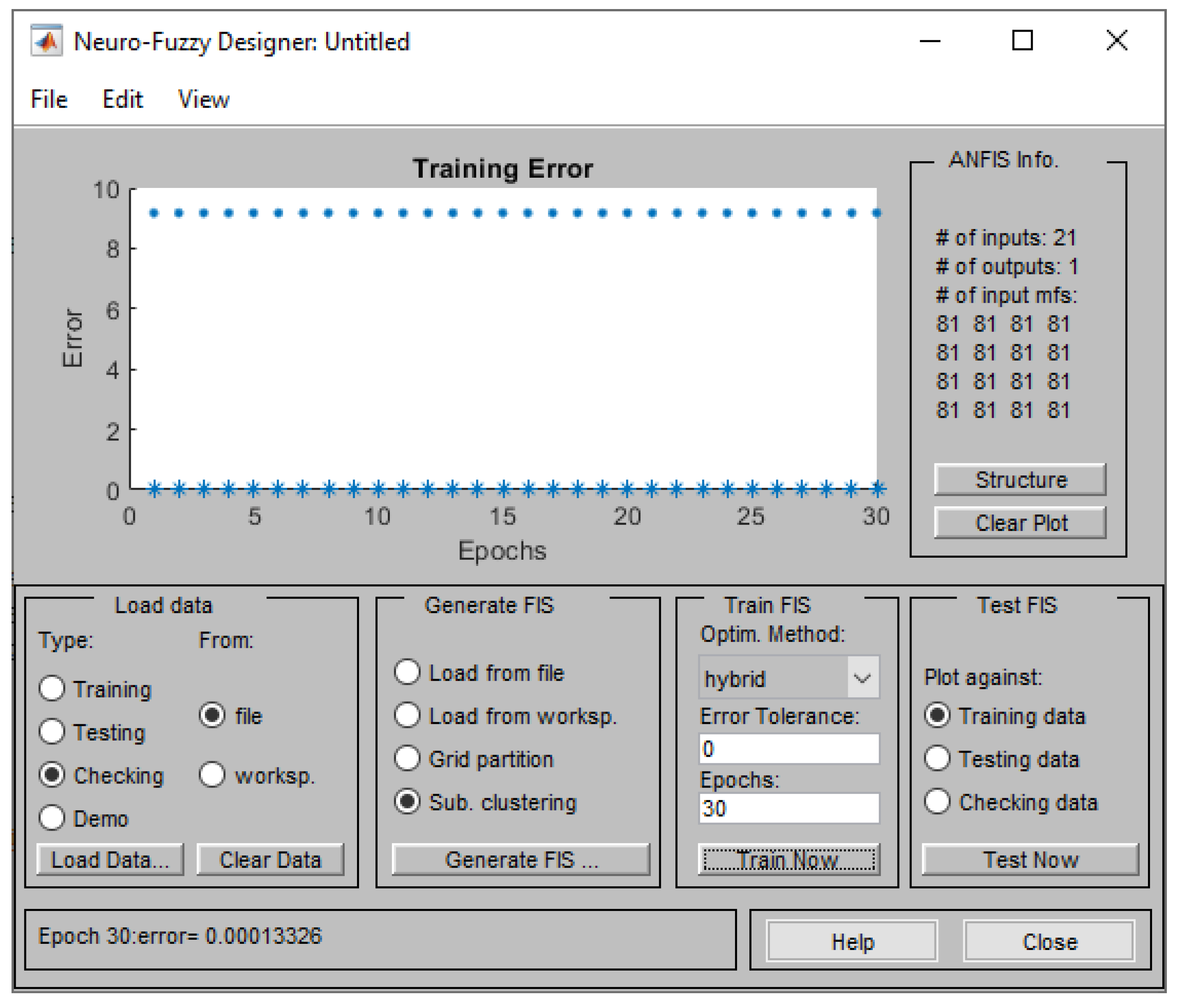
Figure 8.
Testing error against training data (Maximum Stress).
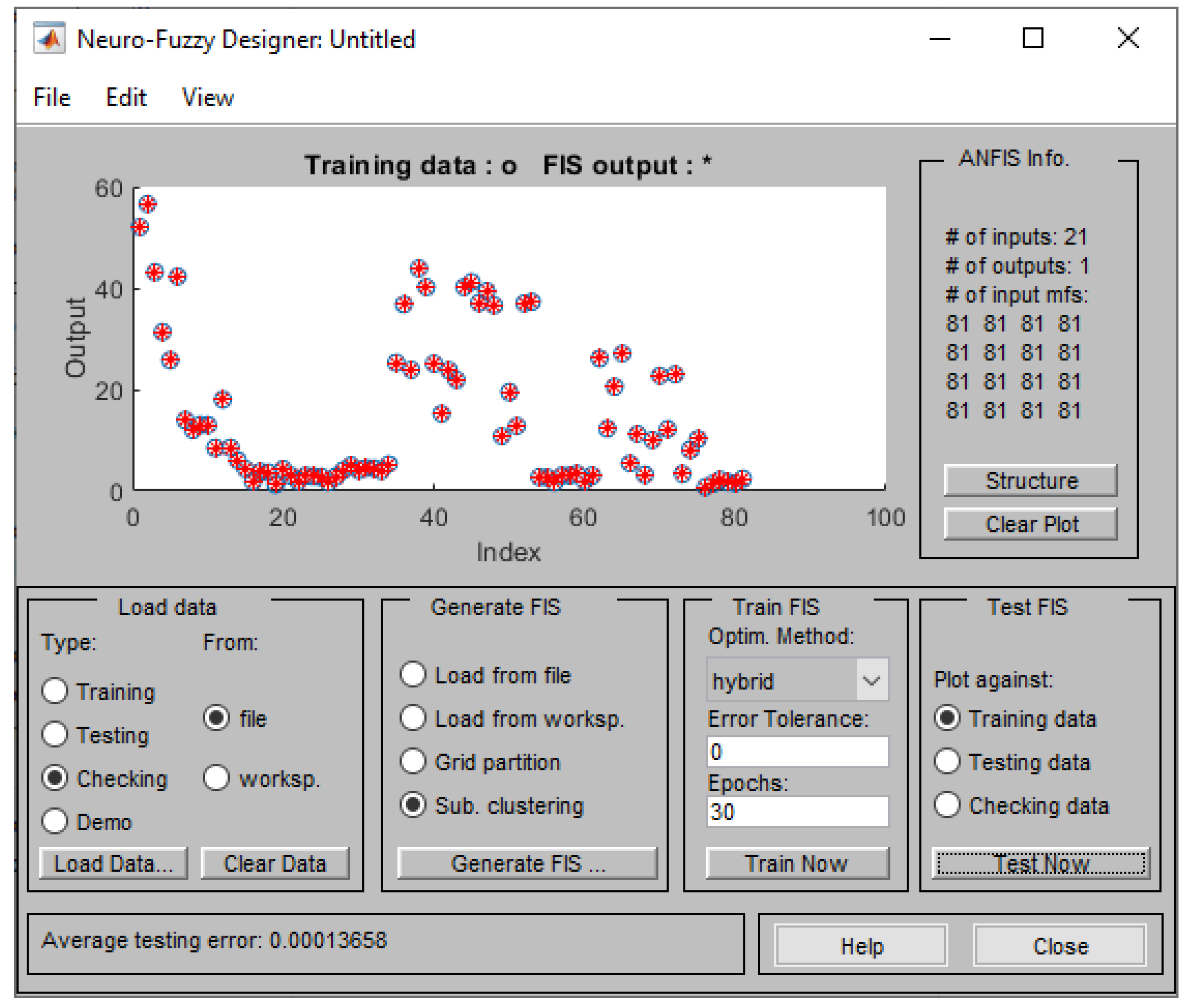
Figure 9.
Testing error against checking data (Maximum Stress.
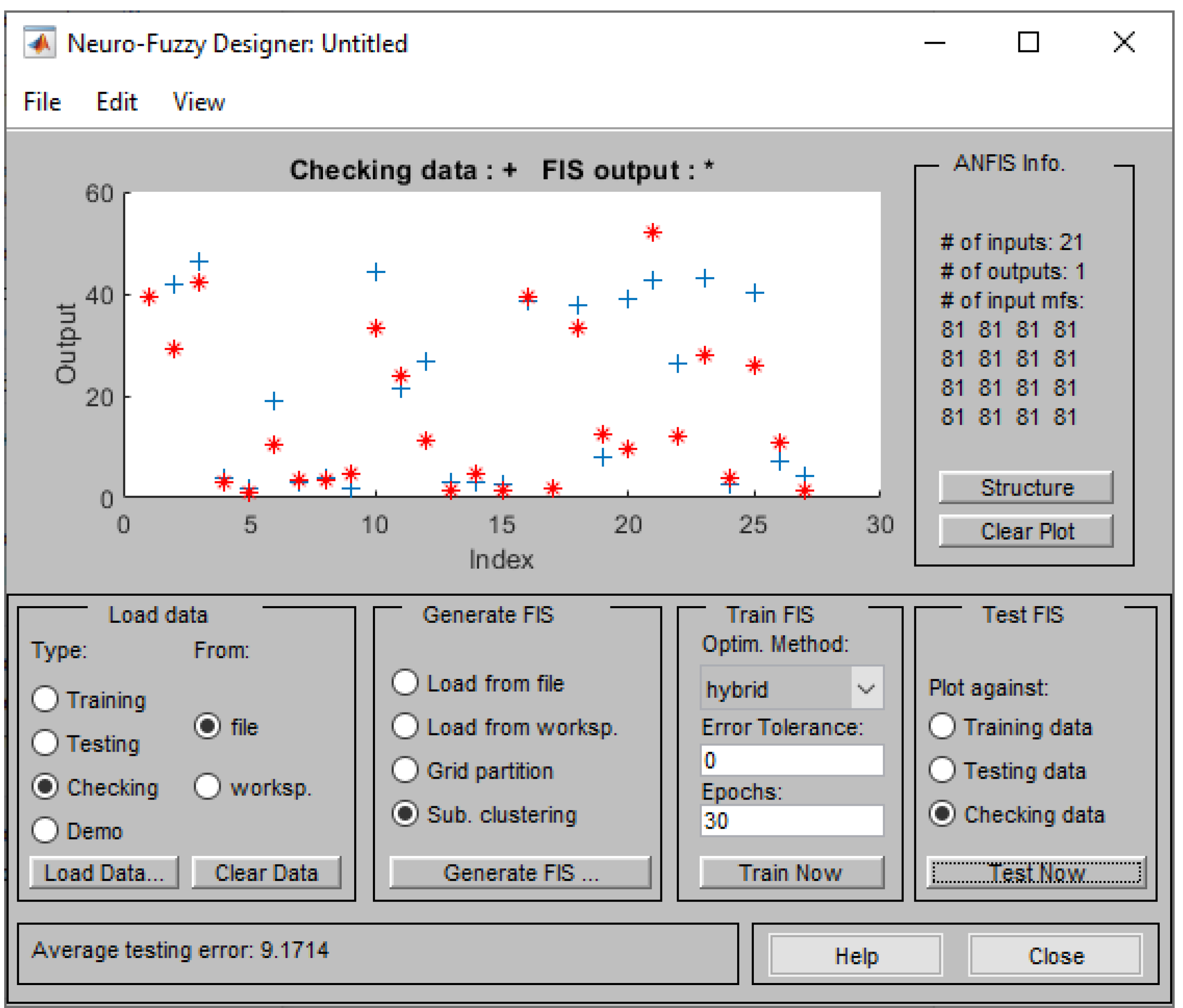
Figure 10.
ANFIS model structure.
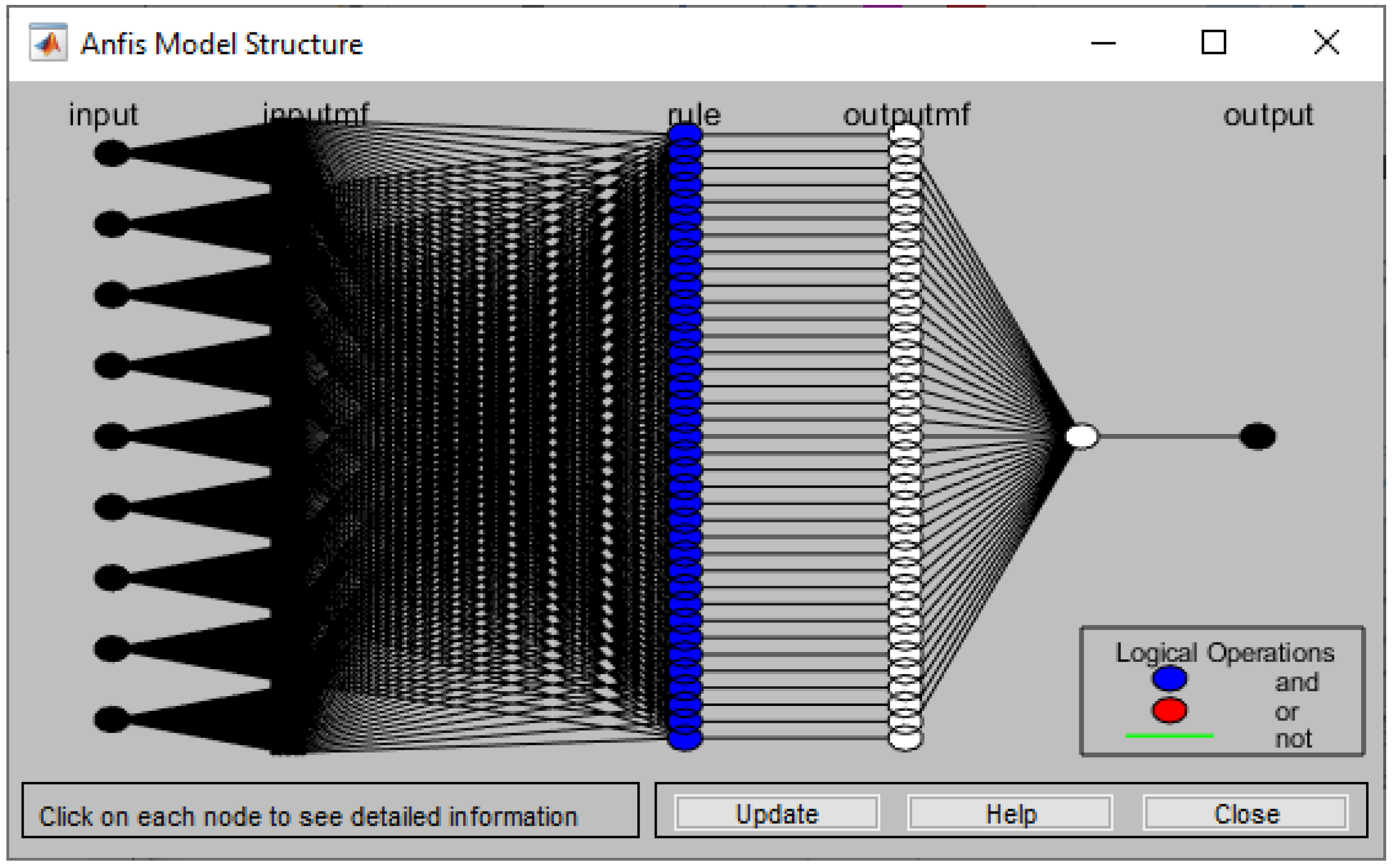
Figure 11.
Data for 9 input variables.
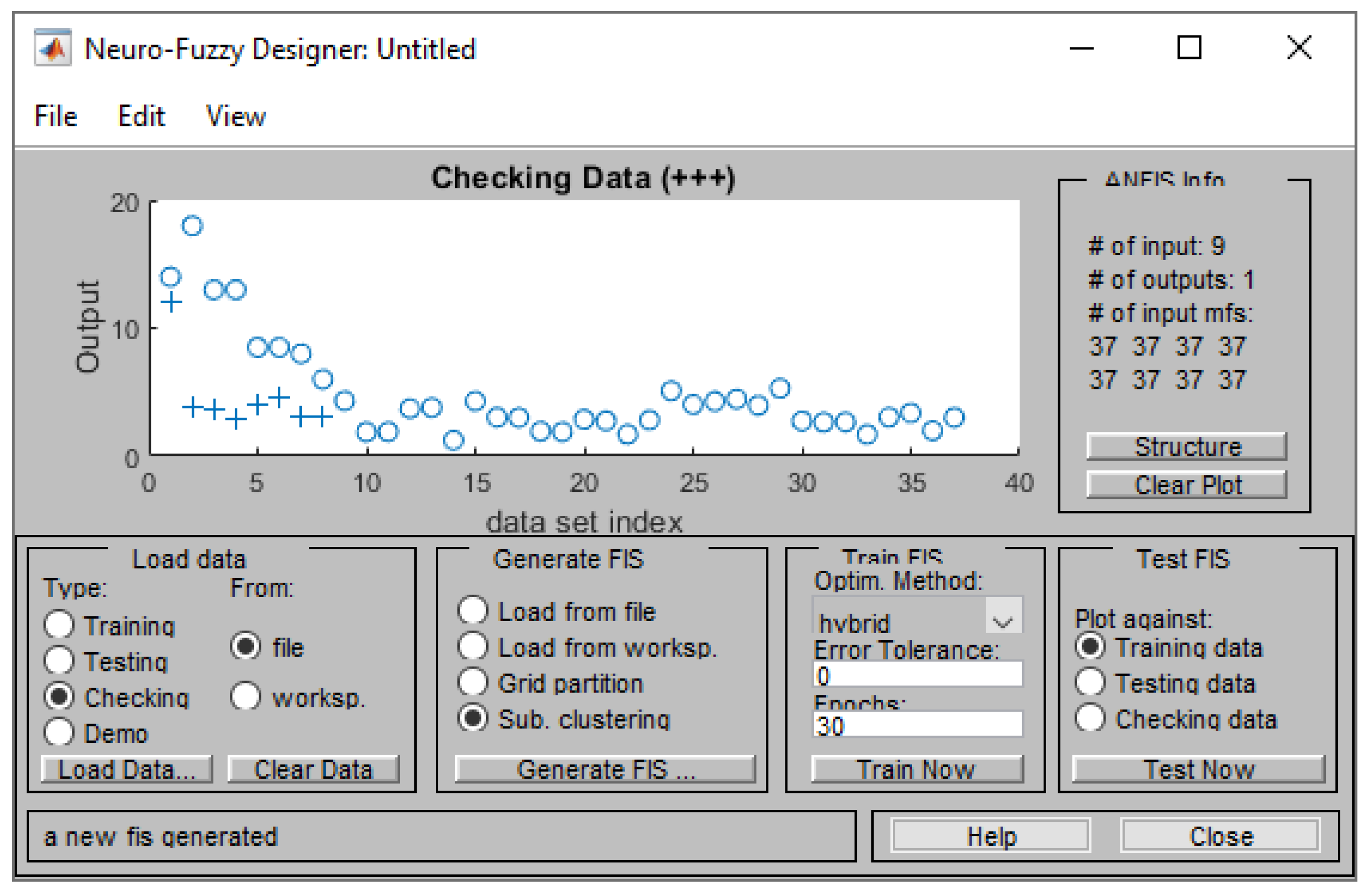
Figure 12.
Training process of the ANFIS.
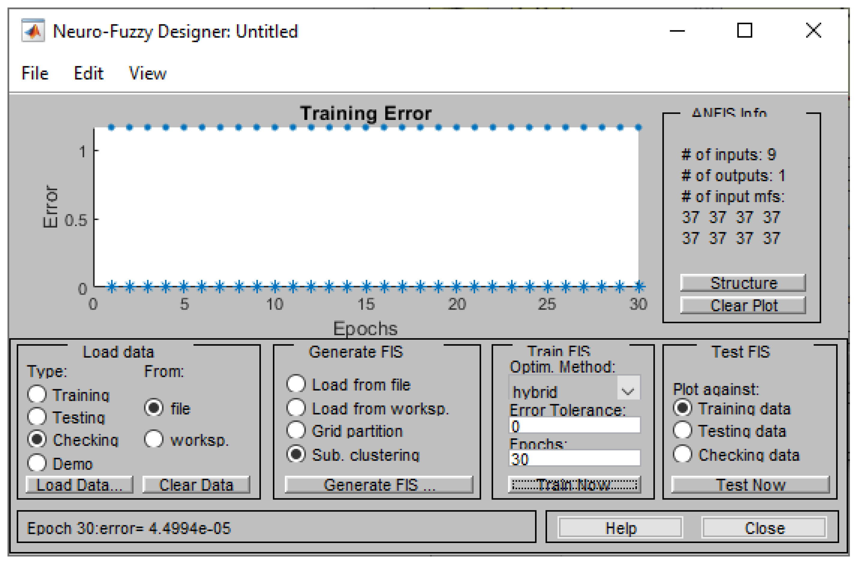
Figure 13.
Testing error against checking data (Maximum Stress).
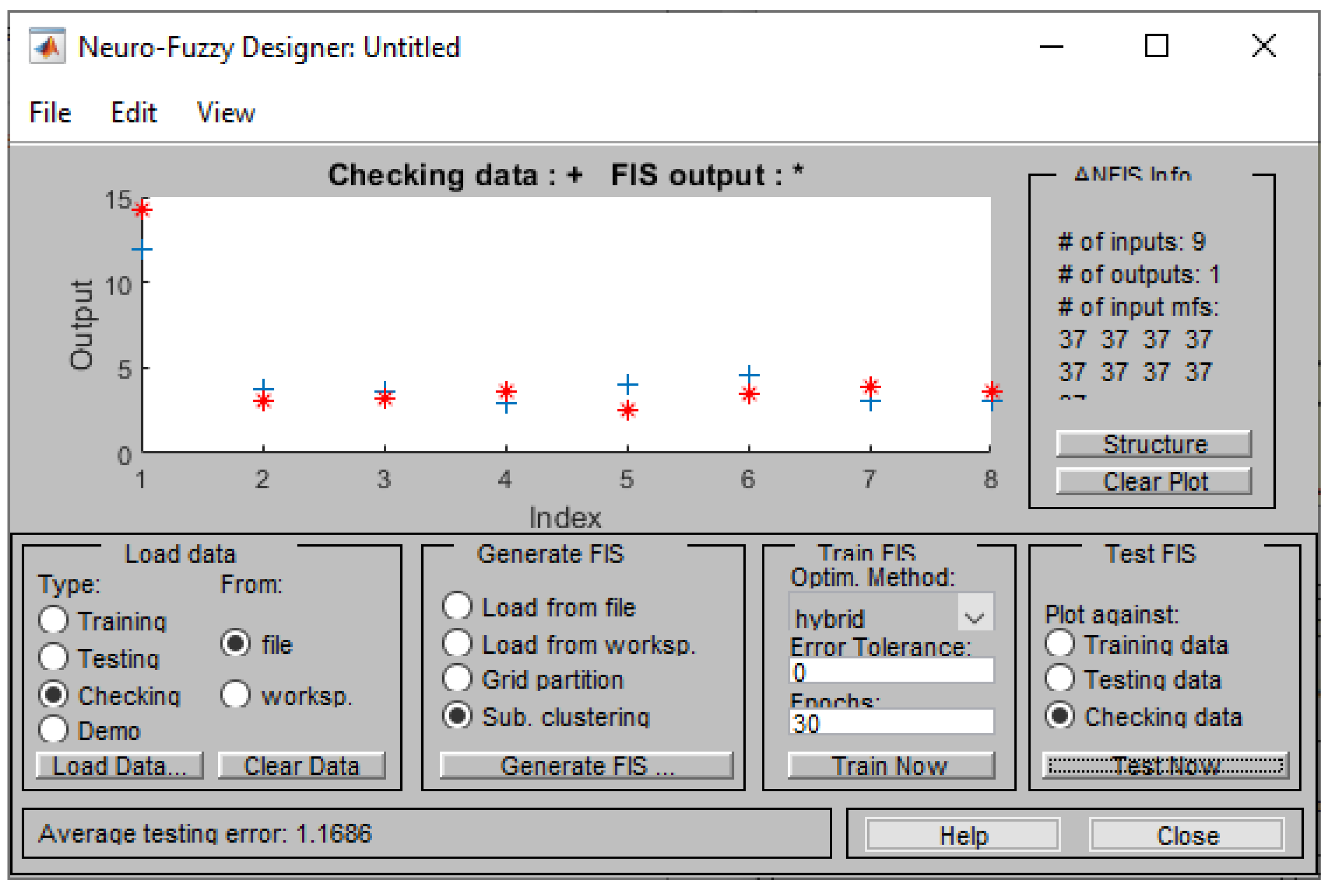
Figure 14.
Error against checking data (Young Modulus).
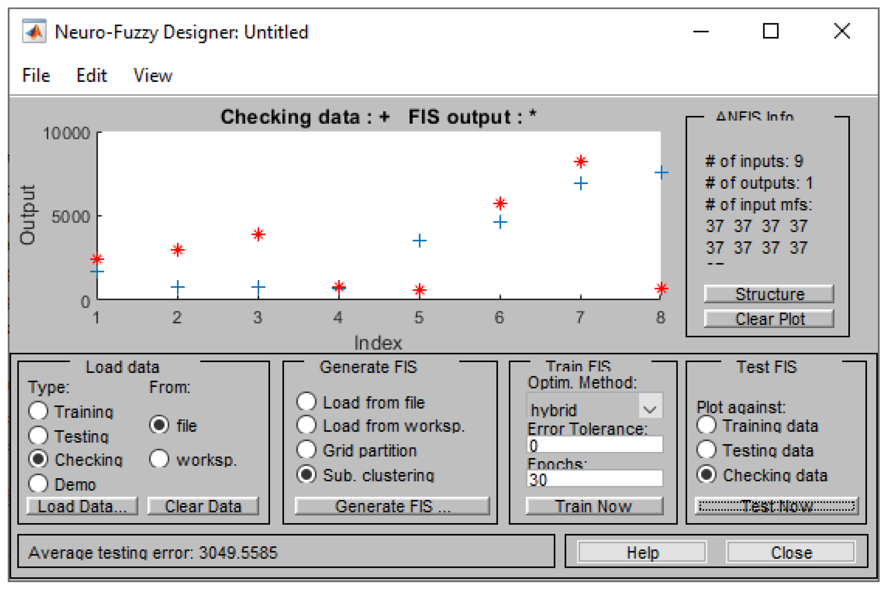
Figure 15.
Error against checking data (Elongation %).
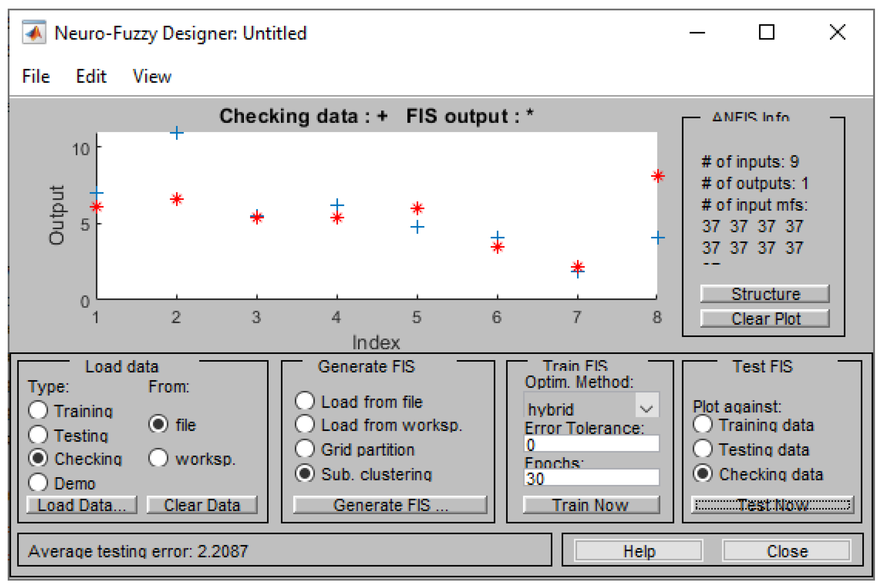
Figure 16.
Test against training data (Maximum Stress).
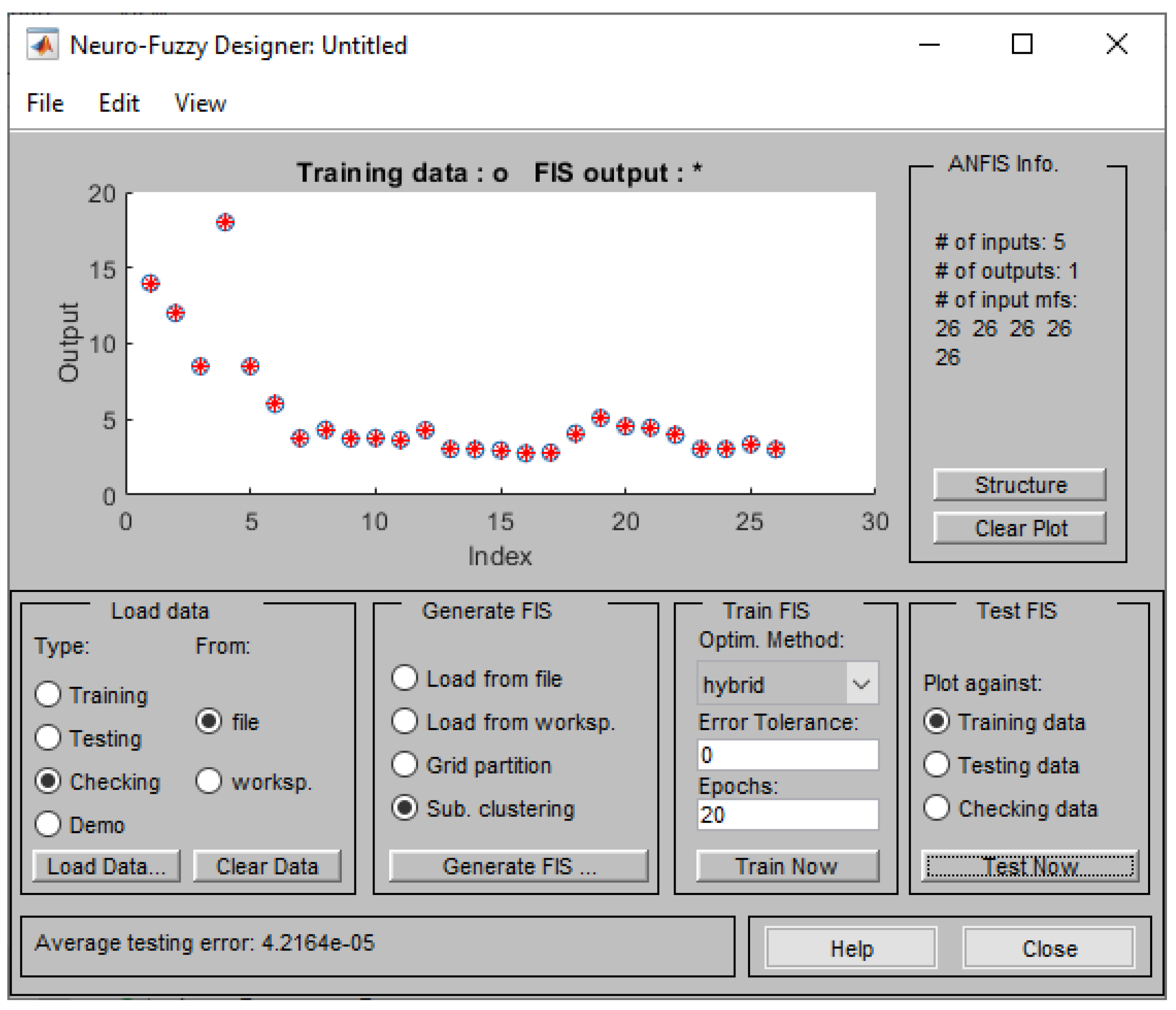
Figure 17.
Test against checking data (Maximum Stress).
Disclaimer/Publisher’s Note: The statements, opinions and data contained in all publications are solely those of the individual author(s) and contributor(s) and not of MDPI and/or the editor(s). MDPI and/or the editor(s) disclaim responsibility for any injury to people or property resulting from any ideas, methods, instructions or products referred to in the content. |
© 2024 by the authors. Licensee MDPI, Basel, Switzerland. This article is an open access article distributed under the terms and conditions of the Creative Commons Attribution (CC BY) license (http://creativecommons.org/licenses/by/4.0/).
Copyright: This open access article is published under a Creative Commons CC BY 4.0 license, which permit the free download, distribution, and reuse, provided that the author and preprint are cited in any reuse.


