
Submitted:
27 June 2024
Posted:
27 June 2024
You are already at the latest version
Abstract
The Marquis of Benicarlo’s House is a prime example of 18th-century Baroque civil architecture in the Valencian region. Inside, it preserves ceramic panels from this period of great historical and heritage value. However, prior to its designation as a Cultural Heritage Site, the building lost some of its most architecturally significant elements, such as the flooring in one of the main rooms, which was decorated with rich iconography. Fortunately, the original tiles from this flooring have been located in the collections of the National Museum of Ceramics. This study presents the recovery and graphic restitution of the flooring based on the pieces found in the museum's collections. This work allows us to understand the original appearance of the flooring before its dismantling and may enable its in-situ restoration through digital ceramic printing techniques, thus returning one of its most unique architectural elements to the building. It also details the process of digitally restoring the flooring to its original location using advanced digitization techniques. This enables the visualization of the hall in its authentic state using virtual reality methods, thereby facilitating its appreciation and dissemination as a heritage architectural space.
Keywords:
decorative ceramics
; baroque
; Marquis of Benicarlo's House
; graphic restitution
; ceramic digital printing
; ceramic flooring
; architectural heritage
; Virtual Reality
1. Introduction
Decorative ceramics have been one of the widely used decorative arts throughout the history of architecture, especially during the Baroque period, known for its opulence and stylistic exuberance. During this time, decorative ceramics not only served a utilitarian function but also became a decorative element used to embellish palaces and noble residences to reference the purchasing power of their owners, due to their elegance and sophistication.
These decorative ceramics were mainly used in under-balconies, kitchen and other rooms, ceramic baseboards, as well as in salon floors. Decorative ceramic floors sometimes replaced or imitated carpets, which occasionally covered them in winter, helping in their preservation. Esclapés in 1737 already mentioned that the tile factories in Valencia had managed to produce ceramic carpets imitating those of Messina [1,2].
However, in many cases, the passage of time and the inevitable effects of deterioration have caused these ceramic works of art to suffer irreparable damage. In other cases, elginism [3] has led that these architectural coverings, like other elements of great artistic and patrimonial value, being stripped from the buildings that housed them.
The restoration of these decorative ceramic coverings becomes a significant challenge, as on one hand, the historical and stylistic authenticity of the pieces must be preserved, and on the other hand, efforts must be made to avoid that their use conditions may affect their original properties and characteristics. Some technical, scientific and interdisciplinary works on conservation and restoration serve as a reference and background to this study, such as the publication of Ascensión Ferrer on ceramic conservation in architectural restoration [4]. In the field of archaeology, it is common to study, analyze and restore ceramic objects with historical and museum-cultural interest in order to preserve them [5,6].
In addition, this type of restoration is of interest to promote both educational and touristic values. For example, the work of Mortara and his team explores educational aspects using virtual environments to enhance the experience of cultural heritage to a wide audience through the use of serious games [7] and the recent work of Amin on Egyptian historical architecture, which uses virtual technologies to enable the acquisition of learning skills to students of architecture in that country [8]. Regarding tourism, it is well known the role of new technologies to improve the visit experience [9,10] and even the visit intention to cultural heritage [11].
The restitution of this hall, including these decorative ceramics, presents a significant challenge, requiring preservation of historical and stylistic authenticity while safeguarding their original properties and characteristics. Digital modeling techniques allow us to graphically restore these architectural elements in their original buildings and to visualize and contextualize them using virtual reality (VR) techniques [12]. The virtual restoration of architectural models requires the use of various techniques, on the one hand those related to the geometric aspects of the architectural space and its details and, on the other hand, to the chromatic aspects. Below we will write a case study in which all these processes can be seen.
2. The Study Case
The Marqués House, also known as Casa dels Miquels, located in the municipality of Benicarló, in the province of Castellón, is a masterpiece of Valencian civil Baroque architecture. It was built in the last quarter of the 18th century by Mr. Joaquín Miquel Lluís, on the site where the old Encomienda house used to stand, headquarters of the Commander of the Order of Montesa. The house consists of a ground floor, mezzanine, main floor, and attic. The building is organized around a large double-height entrance hall and a continuous gallery, accessed by an imperial staircase located in the second bay. Behind the staircase, there is access to a rear garden surrounded by masonry [13]. The most notable elements of the building, besides the staircase, are the ceramic coverings of the chapel, located on the ground floor, the ceramic floors, and decorative paintings of the noble rooms on the main floor, and especially the kitchen completely covered in decorative tiles that recreate culinary scenes from that era. The ceramic pieces were manufactured at the Conde de Aranda factory in Alcora [1,2].
The building was declared a singular BIC (Cultural Heritage) by the Valencian Government on September 28, 2007 [14] and definitively listed as BIC by the Ministry of Culture on December 9, 2008, classified as a 1st category Real Estate with Monument status, with registration number R-I-51-0012141 [15]. Nowadays, the Casa dels Miquels is a private property whose view is not open to the general public. Also, some of the original pavement is located in the National Museum of Ceramics and Decorative Arts “González Martí” (NMCDAGM), as discussed below.
Currently, in one of the main halls on the first floor, the one located at the south-east corner, it can be observed that the central part of the original flooring has been replaced by white ceramic tiles, 20 x 20 cm in size, of recent manufacture, contrasting with the original tiles of the same colour and 21.5 x 21.5 cm in size that make up the perimeter flooring of the room and the adjacent room (see Figure 1).
3. Materials and Methods
3.1. The Ceramic Tiles of the González Martí National Museum
In the storage of the National Museum of Ceramics and Decorative Arts González Martí (NMCDAGM), the pieces of a disassembled ceramic floor are stored. In the text of the Assembly Plan, Annex No. 3 (see Figure 2), the following text appears:
“Hypothetical reconstruction of the panel, following the plan provided by the sellers (Annex 4), which counts 540 tiles. The numbering corresponds to that found on the back of the tiles of each scene (the four seasons and the central panel of time), which have been noted in the count conducted by museum technicians in December 2021. The colours are based on those of the paper in which the tiles were originally wrapped (see illustrations in Annex 2). The rest, in white, corresponds to the white tiles needed to complete the panel. In this scheme, 180 are calculated, and the sales offer included fewer: 103 white tiles wrapped in groups of four in newspaper paper. The remainder consists of 36 tiles from the corners, 216 from the border, 64 from the seasons, and 44 from the central figure, which would be slightly shifted to the left.”
This pavement is classified into different closed plastic boxes containing a specific number of perfectly packaged pieces. They have a first wrapping in white tissue paper and a second one with wrapping paper of different colours, which correspond to the different decorative compositions according to the pavement scheme developed by the museum’s technicians (see Figure 2).
On the wrapping of one of the pieces, the following handwritten text appears:
“Floor from a salon of the Marqués de Benicarló’s house. Alcora, 18th century. In the center, a group representing CHRONOS, and in each corner, a season: SPRING, AUTUMN, WINTER, SUMMER (16 tiles each)”, (See Figure 3).
Although the main production of the Royal Factory of Alcora focused on the manufacture of earthenware and porcelain pieces, the production of tiles and ceramic panels was also significant, judging by those preserved in the factory itself and other panels whose origin has been dated from this historic factory [16].
3.2. Methodology
Within the methodology, we must differentiate between the graphic survey work carried out within the building itself, the data collection work done in the museum, and the graphic processing carried out based on the initial information.
3.2.1. Field Work in the Building
To conduct in-situ data capture within the building, state-of-the-art tools utilizing active 3D imaging systems such as 3D scanners, as well as passive image systems like photography or photogrammetry, have been employed [17]. These tools are utilized for subsequent graphic representation and to obtain a 3D graphical survey or digital replica of the original model. With this model, it becomes possible to clearly identify various structural issues such as diseases, lesions, or deformations affecting the building. This approach ensures that data collection activities do not alter or modify the physical conditions of the buildings, treating them as unchanged samples (non-intrusive measurement), thereby avoiding the high costs associated with employing auxiliary means for data collection [18,19].
The outcome is a tangible reverse architecture representation of the building segment in question. Fieldwork is undertaken to materialize these results, involving data collection to capture the buildings’ metric, geometric, and graphical characteristics.
Sensor-based 3D passive systems, specifically the advancement in automated digital photogrammetric lifting systems, facilitate the creation of highly accurate 3D images defining the object to be represented. These systems generate a point cloud, spatial meshes, and textured meshes with real colour application derived from the obtained photos.
Regarding the massive data-taking systems utilized in these case studies, it is noteworthy to highlight the accuracy and quantity of information provided by the 3D terrestrial scanner based on class-one long-range invisible laser pulses. This scanner allows for fast and agile surveying work. Data capture is supplemented with a digital camera.
A Leica-branded BLK360 3D Imaging Laser Scanner is employed for graphic surveying. This 3D scanner features a built-in spherical imaging system and operates with a single button or device. It weighs 1 kg and measures 16 x 10 cm. It incorporates a high-speed distance measurement system enhanced by waveform scanning (WFD) technology. It is classified as a Class 1 laser according to IEC 60825-1:2014.
Its technical characteristics are:
- Laser Class 1 in accordance with IEC 60825-1: 2014
- Vision field: 360° (horizontal) / 300° (vertical)
- Distances: min. 0.6 - max. 60 m
- Valuation of measurements of points up to 360000 points/sg.
- Precision status: 4 mm at 10 m and 7 mm at 20 m.
The device has 3 integrated HDR digital cameras of 13 M pixels, a full dome capture of 150 Mpx, HDR, LED flash and calibrated spherical image, 360° x 300°.
The tripod used to position it has been a Vanguard Alta Pro 363AT 63-165 cm.
To carry out correct surveys, fieldwork is planned by determining the number of stations to be performed at the main floor of the building. Outside, a minimum of 30% of the scanned surface area is considered; a scan is planned for each smaller room and at least two scans for larger rooms.
For field surveying, the Cyclone Field 360 software installed in a tablet with the Android operating system can be used. Medium quality of the scanner has been chosen and images have been captured in HDR. This software allows to visualize both scanning and images in real time, and to pre-align stations in situ by facilitating subsequent point cloud registrations.
The data collection work of the building has been completed by creating a photogrammetric model of the main floor using Matterport software, utilizing a RICOH THETA Z1 360º photographic camera with the following technical specifications:
- Image sensor: 1.0" × 2 back-illuminated CMOS
- File size (still images): RAW: 7296 × 3648; JPEG: 6720 × 3360
- Aperture: F2.1, F3.5, F5.6
- Lens construction: 14 elements in 10 groups × 2
- Capture mode: still image / video: automatic, shutter speed priority, ISO sensitivity priority, aperture priority, manual
- Capture distance: approximately 40 cm to ∞ (from the front of the lens)
- Exposure control mode: AE program, AE shutter speed priority, AE ISO sensitivity priority, manual exposure
- Exposure compensation: manual compensation (-2.0 to +2.0 EV, in 1/3 EV steps)
-
ISO sensitivity (standard output sensitivity): still image / video: [Auto] ISO 80 to 6400, adjustable upper limit; [Manual] ISO 80 to 6400The resulting 3D model can be viewed at the following link:
3.2.2. Field Work in the Museum
To capture images of the ceramic pieces a 10.2-megapixel Nikon D-80 digital camera and a Nikon 5200 24-megapixel camera, fitted with a conventional lens between 18-135 mm, with a focal aperture of f/3.5-5.6, a Sigma wide-angle 8-16 mm lens and a focal aperture of f/4.5 to 5.6 mm.
The camera has been placed on an adjustable focus support stand on a table. This support allows taking orthogonal images of the pieces. To improve the camera adjustment, a millimeter template base has been placed on the support table, and once the camera has been adjusted, the different ceramic pieces have been placed to capture the images. To prevent lens movements, the images have been taken using a remote trigger using the SnapBridge application (see Figure 4).
In addition to taking the photographic capture, both the obverse and reverse, of each of the pieces, they have been weighed with a digital weighing machine and measured with a caliper.
3.2.3. Graphic Process
To be able to work with the point clouds obtained with the scanner, nine different point clouds are recorded by assembling and orienting them. This operation is performed with Leica Geosystems Cyclone Register 360 software. It imports *.blk files from the scan that are registered to obtain three homonymous points located in each cloud to generate a whole cloud. With the same software, it is possible to clean the site’s point cloud and to orientate it (see Figure 5).
From the point cloud, it has been possible to obtain a digital model of the southeast room where the original pavement was located.
The next step has been the digital processing of the images obtained from each of the ceramic tiles. For this purpose, they have been encoded and numbered according to the initials of each of the sets. For the completion of this process, the graphic restitution work of the pavement of the Sanjoans Palace [20] has been used as a reference.
The images have been rectified using PTlens software to correct the fisheye lens distortion, also known as “barrel distortion” (see Figure 6 and Figure 7).
In most of the images, this rectification process has been sufficient due to the conditions of capture using a support orthogonal to the pieces. In some cases, due to the warping of some of the pieces, it has been necessary to rectify them later with ASRix software to obtain fully orthogonal images of the pieces. The photographs that are rectified by this software are: EA07, BA01, BA02, BA03, BA04, BA05 and BA10.
Once each of the images has been rectified, they have been cropped to remove the background using the GIMP photographic retouching tool (see Figure 8).
4. Results
In this section, the results obtained in the present work will be presented. These have been classified into two parts: graphical restitution of the pavement, digital modeling of the room, and visualization of the set using VR techniques.
4.1. Graphic Restitution of the Flooring
Once cleaned and retouched, the images of the tiles, they have been assembled into the different decorative panels using GIMP software on a grid of 21.5 x 21.5 cm, creating a subset for each pattern: Spring, Summer, Autumn, Winter, Chronos, corner border, brown border, blue border, and white panel. Four Season panels are made up of 16 tiles, Chronos panel of 44 pieces and border and white panels of 9 tiles each one (See Figure 9, Figure 10 and Figure 11).
4.2. Graphical Modelling of the Hall
In this section, the results obtained from the modeling of the room using the various point clouds and images collected during the fieldwork will be presented.
4.2.1. Generation of the Point Cloud
To process the point clouds acquired from the scanner, we utilized LEICA GEOSYSTEMS CYCLONE REGISTER 360 software. This software facilitated the recording and integration of the nine point clouds by importing *.blk files from the scan and aligning them to identify three common points in each cloud, resulting in a consolidated point cloud. Furthermore, the software offered capabilities for refining and orienting the point cloud.
Using this unified point cloud data, we generated a digital model of the southeast hall, the location of the original pavement.
To enhance the clarity of the point cloud, we employed the "smooth surfaces" tool, which effectively eliminated excess points, focusing solely on the walls and floor. Any unselected areas were highlighted in red and subsequently removed automatically (refer to Figure 14).
4.2.2. Meshing and Texturing of the Hall
To create the mesh, the point cloud has been imported into the Cyclone 3DR program in an *.e57 format. Then, the "3D mesh creation" tool has been selected, and the "two-step meshing" option has been chosen (see Figure 15).
The next step has been to select "refine mesh from cloud". From this process, a mesh of the Hall has been obtained. The next step has been to improve the mesh for subsequent texturing.
Afterwards, the "global smoothing" tool has been used, and the "smooth noise" tool has been selected, thus achieving a more homogeneous model. However, there were still several errors in the mesh that need to be corrected using different modelling tools.
Using the "clean/separate," "bridge," "fill holes," and "smooth mesh" tools, all poorly modelled parts have been eliminated, and the mesh has been adjusted. To delineate each part of the room for subsequently applying each texture in its correct place, a polyline has been created on each one of the edges, its projection onto the mesh has been performed, a constrained mesh has been created, and subsequently the "sharp edges" tool has been applied (see Figure 16).
With the GIMP software, the three spherical images captured by the scanner itself have been edited to texture the room The main edits focus on fixing the lights that are generated on the walls and ceiling, removing the stacked tiles on one side of the hall, and eliminating the bed’s headboard (see Figure 17).
The adjusted and refined mesh has been textured using different spherical images of the room once edited. With this procedure, a fully textured mesh of the room has been obtained (see Figure 18).
For the creation of the flooring, two textures have been created from scratch: one depicting the fully decorated flooring for the main room and another one featuring a module of 4 x 4 white tiles for the adjacent room.
To facilitate the flooring placement, the flooring has been divided into two parts and separated from the rest of the room, leaving a mesh of the walls and ceiling, one mesh on one floor, and another mesh on the other one. Each texture has been applied separately by importing each image into the program, and using the "texture adjustment" tool, both textures have been applied by adjusting the values of each image, we position the images in their place.
By adjusting the values of each image, the images have been placed in their correct positions. The result can be observed in Figure 19 and Figure 20.
The result is a complete textured virtual model of the room that integrates the decorated ceramic flooring in its original location (see Figure 21).
4.2.3. Visualization of the Hall Using VR Techniques
To upload the model to the Sketchfab platform, the *.obj file size has been reduced using MeshLab software as follows: Filters -> Remeshing, Simplification, and Reconstruction -> Simplification: Quadric Edge Collapse Decimation (with texture) -> Target number of faces 500,000.
The model has been uploaded to the Sketchfab platform, where it is possible to perform a 3D visualization of the model and navigate through it. The link to view the model is as follows: https://skfb.ly/oORSq (see Figure 22)

5. Discussion
5.1. Physical Restitution through Digital Ceramic Printing Technology
In this context, the introduction of digital ceramic printing technology has revolutionized the field of restoration and preservation of decorative ceramics. This innovative technology allows for precise and detailed reproduction of historical designs, providing an effective solution for restoring damaged or dismounted decorative elements, as in the case of the Marquis of Benicarló’s House or other similar historic buildings.
The methodology for replicating the decorative designs and colour palette of historic tiles developed by the Institute of Ceramic Technology (ITC) in collaboration with the company Fritta, S.L., facilitates the replacement of damaged or lost pieces, as well as the substitution of originals exposed by copies to ensure their preservation in optimal conditions. This methodology consists of three stages: characterization of the materials to be replicated, acquisition and digital processing of the decorative designs to separate the different colours, and development of a set of digital ink for inkjet printing that allows replicating the colour palette of the tiles [21].
5.2. Virtual Restitution through Digital Tools and VR Visualization
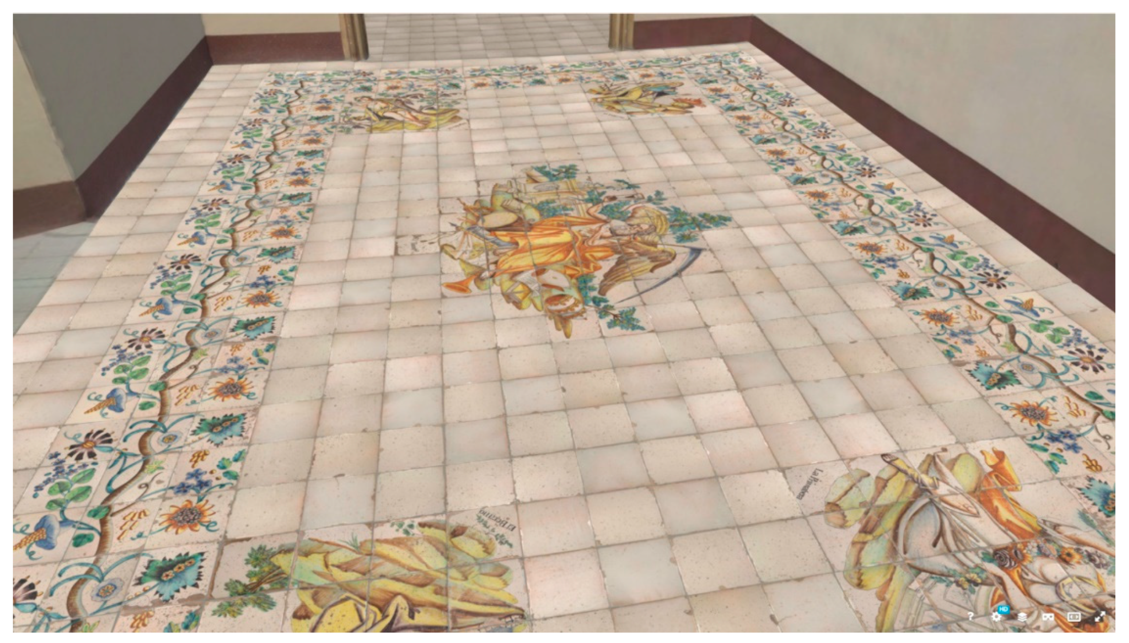
As a result of this digital treatment process, it is possible to offer better accessibility to architectural assets that would otherwise be difficult to access due to their private nature. In addition, the unique ceramic pavement is currently stored in the warehouses of the NMCDAGM. Therefore, this study, through digital visualization techniques, exhibits in an open and freeway "hidden" cultural assets to the population. These assets are not only better documented, but also exposed for other purposes of architectural, educational and/or touristic interest that help disseminate these cultural contents, and even open doors to further developments focused on the field of education and/or tourism, in tune with some of the literature mentioned [7,8,9,10,11] (see Figure 23 and Figure 24).
6. Conclusions
This work has allowed verifying that the pavement preserved in the archives of the National Museum of Ceramics and Decorative Arts González Martí corresponds to the dismantled pavement of one of the noble rooms of the Marquess’s House, as the dimensions of the dismantled panel (6.45 x 4.12 m) match with the measurements of the panel preserved in the MNCADGM, as well as by the annotations found on the packaging of one of the pieces.
The good condition of the pieces that make up the main decorative motifs of the pavement (Chronos and Four Seasons) has been verified, although some of their pieces have suffered minor damage or breakages during the dismantling process.
Regarding the pieces that make up the decorative borders, many pieces have been found to have severe damage to their visible face due to use, although others are in better condition. This difference is undoubtedly due to their placement in areas of greater or lesser foot traffic within the room. The repetition of the module has allowed the creation of three patterns: corner border, blue border, and brown border. A complete recreation of the pavement design has been possible using these three patterns.
Due to the high heritage value of the ceramic pieces and their state of preservation, they should be fully restored by specialized technicians before their exhibition or relocation.
While the best way to enhance the value of this or any historical pavement is its placement in its original position as flooring, this poses a problem of conservation and maintenance.
A common solution is to place a protective sheet of transparent polyethylene, although these coverings prevent wear from abrasion, they do not prevent damage from impacts or overloading.
Another added problem is that these polyethylene sheets became yellow over time, so the pavements cannot be visualized with their original tone and brightness.
The methodology for reproducing historical tiles from an 18th-century Valencian kitchen, known for the complexity and richness of its chromatic decoration developed by technicians from the ITC [21], could be applied to the Four Seasons Pavement of the Marquis of Benicarló`s House.
Therefore, an alternative solution to relocating the original pieces would be to manufacture a copy of the pavement using digital printing techniques from the digital model developed in this study and placing it in its original location, restoring the hall to its original architectural and heritage value.
This technique can be applied to other similar cases of ceramic flooring, or coverings removed from their original buildings.
Finally, the study serves as a starting point for the open nature of its results, to very diverse uses, mainly in the field of education, musealization or even in the promotion of tourism.
Author Contributions
Conceptualization, J.A.M.-M; methodology, J.A.M.-M. and J.G.-O.; software, J.A.M.-M. and J.G.-O; validation, J.A.M.-M. and J.G.-O; formal analysis, J.A.M.-M. and J.G.-O; investigation, J.A.M.-M. and J.G.-O ; resources, J.A.M.-M. and J.G.-O ; data curation, J.A.M.-M.; writing—original draft preparation, J.A.M.-M. and J.G.-O; writing—review and editing, J.A.M.-M. and J.G.-O; visualization, J.A.M.-M. and J.G.-O; supervision, J.A.M.-M. and J.G.-O ; project administration, J.A.M.-M.; funding acquisition, J.A.M.-M. All authors have read and agreed to the published version of the manuscript.
Funding
This research was funded by the Research Promotion Plan of the Jaume I University of Castellón, grant number 24I059. It has been carried out within the research project "Opening doors: a walk through the manor houses of the 17th and 18th centuries" developed by the ARDIPA Research Group.
Data Availability Statement
Data not contained within the article but related to this study may be made available upon reasonable request from the corresponding author.
Acknowledgments
We would like to express our gratitude for their work in the completion of this project to the students Pablo Cantero Pitarch and especially to Sebastián Pla Bernard, who completed their internships in the ARDIPA research group. We also extend our thanks to the current owner of the building, the architect Mr. Santiago Espinosa, for opening the doors of the building, allowing to conduct the data collection work, for his great efforts in the conservation of this magnificent jewel of Valencian Baroque architectural heritage, and for providing us with essential information to carry out this work. Additionally, we would like to thank the National Museum of Ceramics and Decorative Arts González Martí for granting us access to their archives to conduct this research, and especially to Mr. Guillermo Roldan Villareal, Technical Officer of the Documentation Area, and to Mr. Jaume Coll Conesa, the museum’s director.
Conflicts of Interest
The authors declare no conflicts of interest.
References
- Gil-Saura, Y. Arquitectura de la época barroca en Castellón; Bérchez-Gómez, J., Director; Universitat de València: Valencia, 2002. (Doctoral thesis). URI: http://hdl.handle.net/10550/38543.
- Pérez-Guillém, I. V. La cerámica arquitectónica valenciana. Los azulejos de serie, siglos XVI-XVIII; Generalitat Valenciana: Valencia, 1999.
- Delicado Martínez, J. Monumentos desaparecidos de la Comunidad Valenciana. In El Palacio de los Condes de Oliva; Aldana Fernándes, S., Ed.; Consell Valencià de Cultura: Valencia, 1999.
- Ferrer Morales, A. La cerámica arquitectónica: su conservación y restauración, 2007.
- Carrascosa Moliner, B. La conservación y restauración de objetos cerámicos arqueológicos, 2009.
- Lastras Pérez, M.; Yusa Marco, D. J.; Munera Torró, A. L. Restauración de cerámica arqueológica: la eficacia del estrato intermedio. Arché 2011, 6, 213-220. http://hdl.handle.net/10251/33516.
- Mortara, M.; Catalano, C.; Bellotti, F.; Fiucci, G.; Houry-Panchetti, M.; Petridis, P. Learning cultural heritage by serious games. J. Cult. Herit. 2014, 15 (3), 318-325. [CrossRef]
- Amin, F. Virtual reality adaptability in architecture heritage education egyptian universities survey. Int. J. Archit. Eng. Urban Res. 2023, 6 (1), 148-166. [CrossRef]
- Kim, M.; Lee, C.; Jung, T. Exploring consumer behavior in virtual reality tourism using an extended stimulus-organism-response model. J. Travel Res. 2018, 59 (1), 69-89. [CrossRef]
- Alkhaliel, A. Applying virtual reality tourism to cultural heritage sites: a case study on al-diriyah. Univ. Sharjah (Uos) J. Humanit. Soc. Sci. 2022, 19 (3). [CrossRef]
- Atzeni, M.; Chiappa, G.; Pung, J. Enhancing visit intention in heritage tourism: the role of object-based and existential authenticity in non-immersive virtual reality heritage experiences. Int. J. Tour. Res. 2021, 24 (2), 240-255. [CrossRef]
- Puyuelo, M.; Higón, J. L.; Merino, L.; Contero, M. Experiencing augmented reality as an accessibility resource in the UNESCO heritage site called “la lonja”, Valencia. Procedia Comput. Sci. 2013, 25, 171-178. [CrossRef]
- García Lisón, M. A.; Zaragozá, A. Benicarló. In Catálogo de Monumentos y Conjuntos de la Comunidad Valenciana; Generalitat Valenciana: Valencia, 1983; Vol. X, pp 161-165.
- DECRETO 169/2007, de 28 de septiembre, del Consell. BOE 24 de enero de 2008. [WWW document]. URL http://www.cultura.gva.es/es/web/patrimonio-cultural-y-museos/bics (accessed 31 March 2024).
- Inventario general del patrimonio cultural valenciano. Sección 1ª. Bienes de Interés Cultural [WWW document]. URL http://www.cultura.gva.es/es/web/patrimonio-cultural-y-museos/bics (accessed 31 March 2024).
- Coll-Conesa, J. Historia de la Cerámica Valenciana; AVEC: Valencia, 2009; [WWW document]. URL http://www.avec.com/historia_de_la_ceramica_valenciana.asp (accessed 31 March 2024).
- Cabeza-González, M.; Soler-Estrela, A.; Máñez-Pitarch, M. J.; Garfella Rubio, J. T. La cantería gótica en la comarca del Maestrazgo. Modelos virtuales de los sistemas abovedados de tres capillas ochavadas. EGE Rev. Expres. Gráfica Edif. 2014, 8, 106-112. [CrossRef]
- Guerra, F.; Riveiro, B.; Arias, P. Non-invasive techniques for the documentation and monitoring of cultural heritage sites: A review. J. Cult. Herit. 2019, 36, 311-322.
- Murcia-Soler, M.; Abadía-Barrero, C. E.; Otero, M.; Tomé, P. Review on non-destructive techniques for the diagnosis of the built heritage. Heritage 2020, 3 (2), 522-541. [CrossRef]
- Julián-Querol, F.; Julián-Querol, T.; Orenga-Suliano, L.; Padilla-Julian, J. T. Cerámica Zoo-Mórfica del palacio de Santjoans. [WWW document]. URL http://www.santjoans.es/Santjoans.html#presentation (accessed 20 November 2024).
- Lucas, L.; Blanco, C.; Comes, P.; Gosalbo-Nebot, A.; Orts-Tarí, M. J.; Mestre-Beltrán, S.; Bou-Solsona, E. Use of digital jet printing in the reproduction and recovery of architectural ceramic heritage. INTERCERAM 2008, 57 (3), 186-192.
Figure 1.
Marquis of Benicarlo’s House. Floor view of the south-east hall of the main floor get with Matterport.
Figure 1.
Marquis of Benicarlo’s House. Floor view of the south-east hall of the main floor get with Matterport.
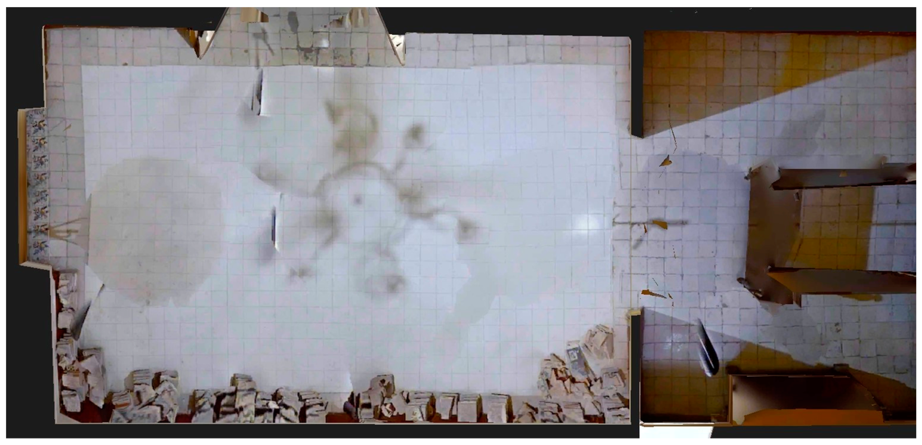
Figure 2.
Assembly Plan of the flooring, Annex No. 3. NMCDAGM storage.
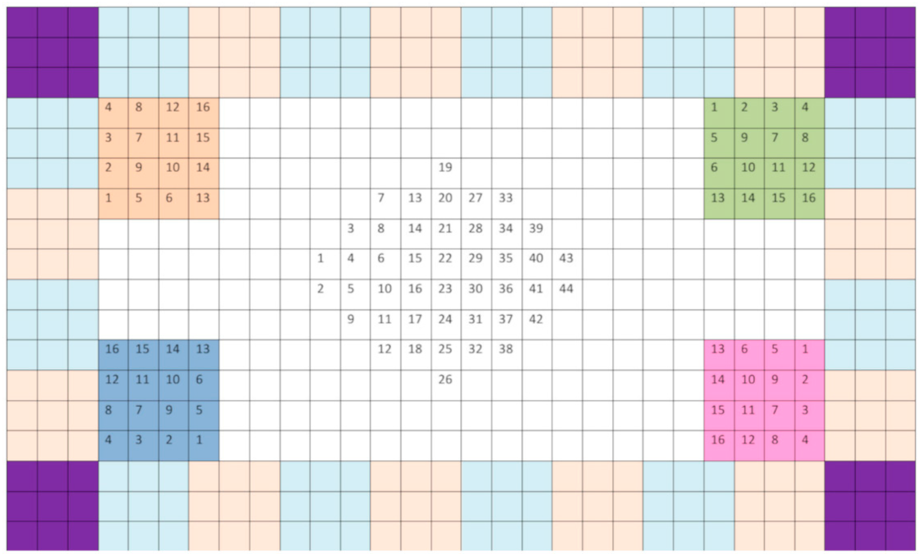
Figure 3.
Handwritten text on the wrapping of one of the pieces.
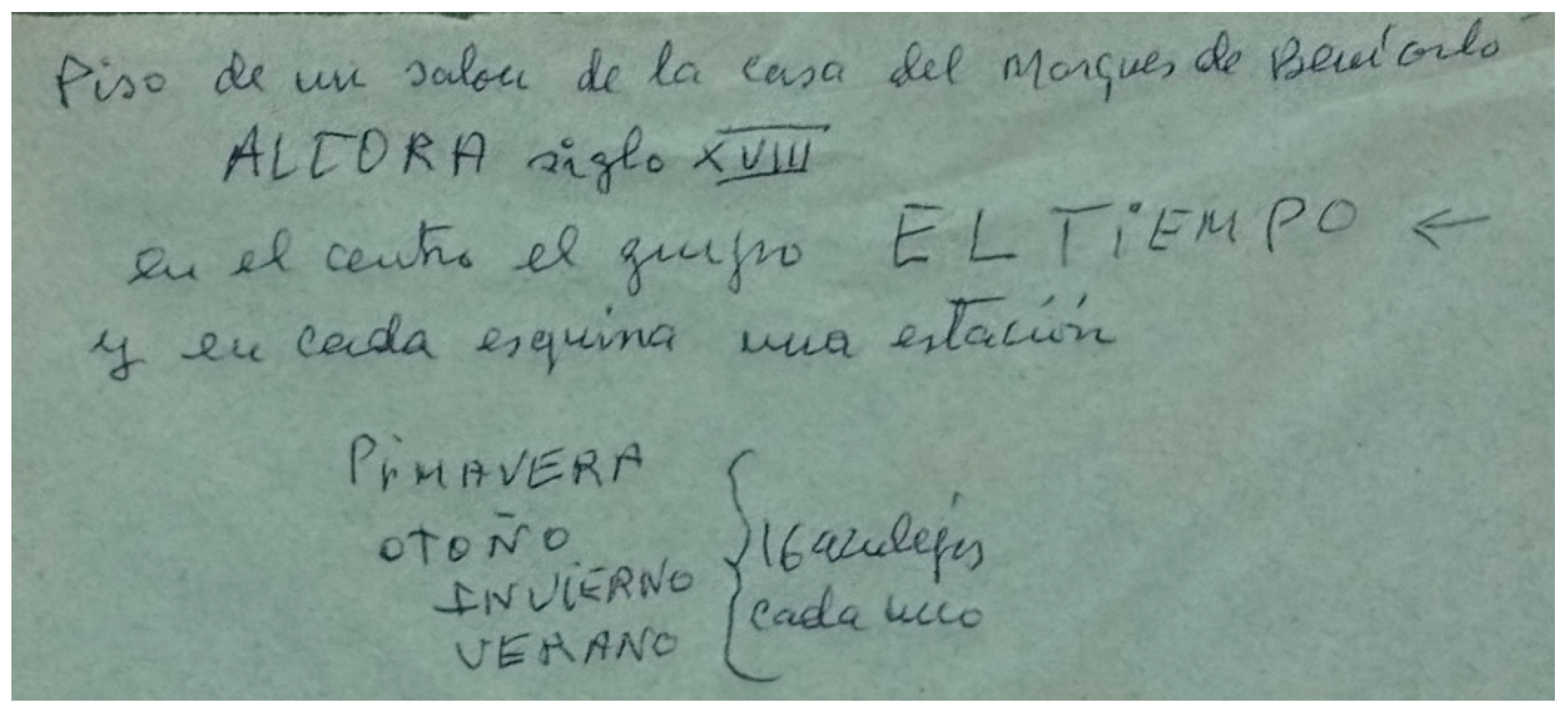
Figure 4.
Photo shooting with adjustable focus support stand on a table.
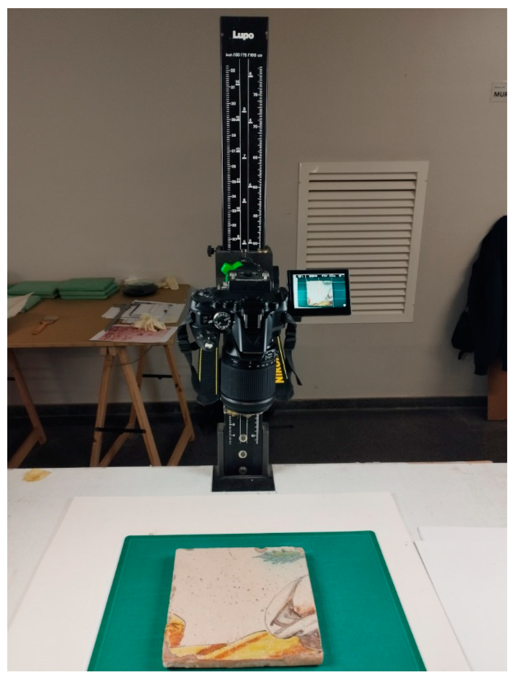
Figure 5.
Registered and oriented point cloud of the set.
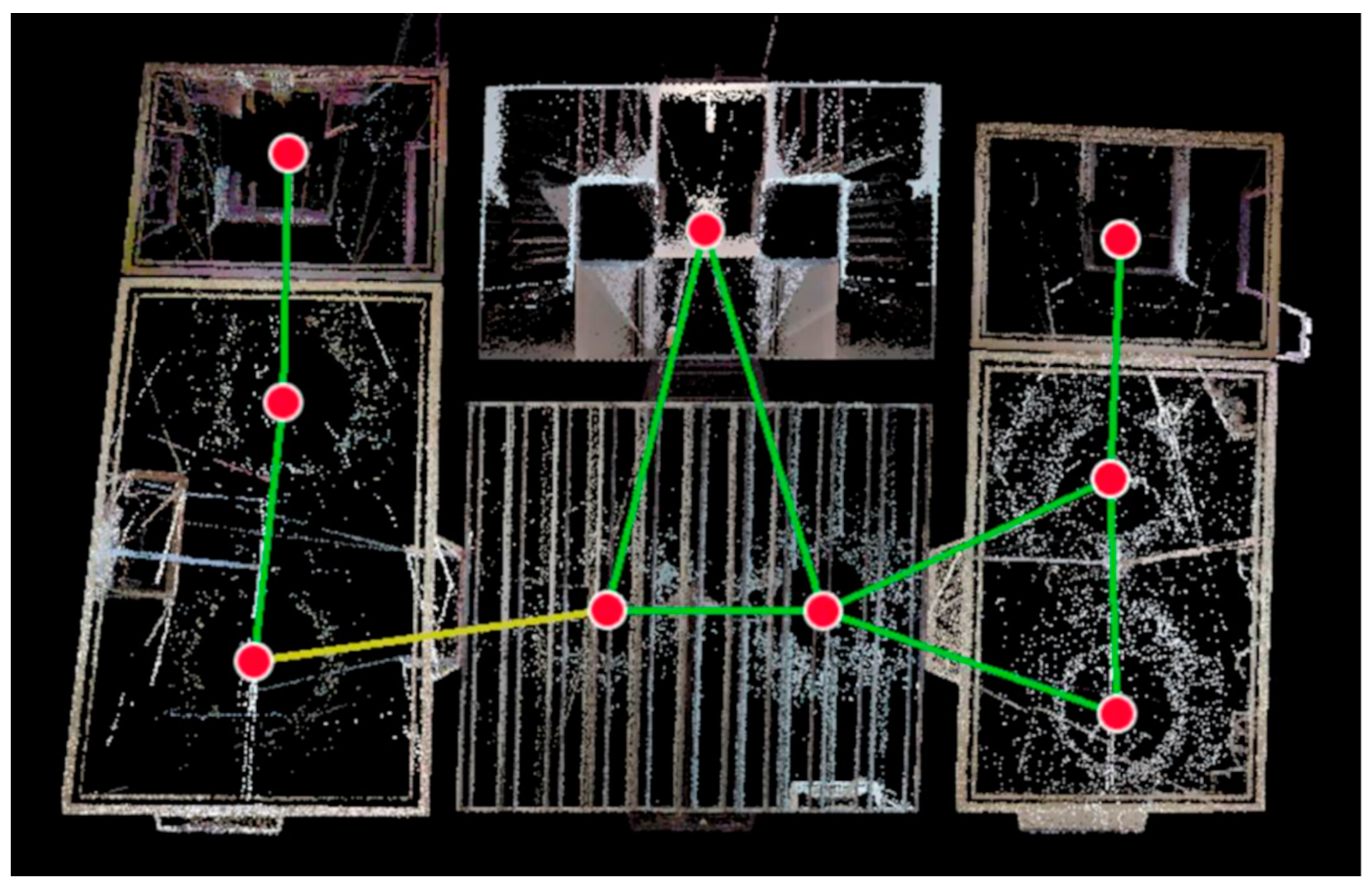
Figure 6.
Original picture of piece PA08. Springtime panel, piece number 8 obverse.
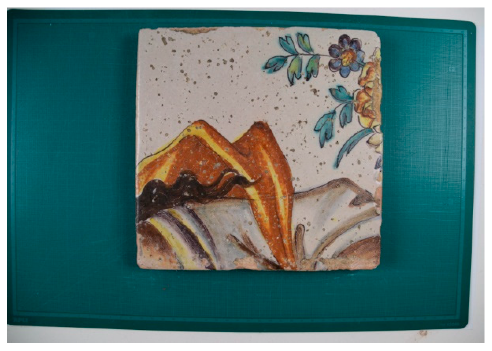
Figure 7.
Piece PA08 rectified with PTLens software.
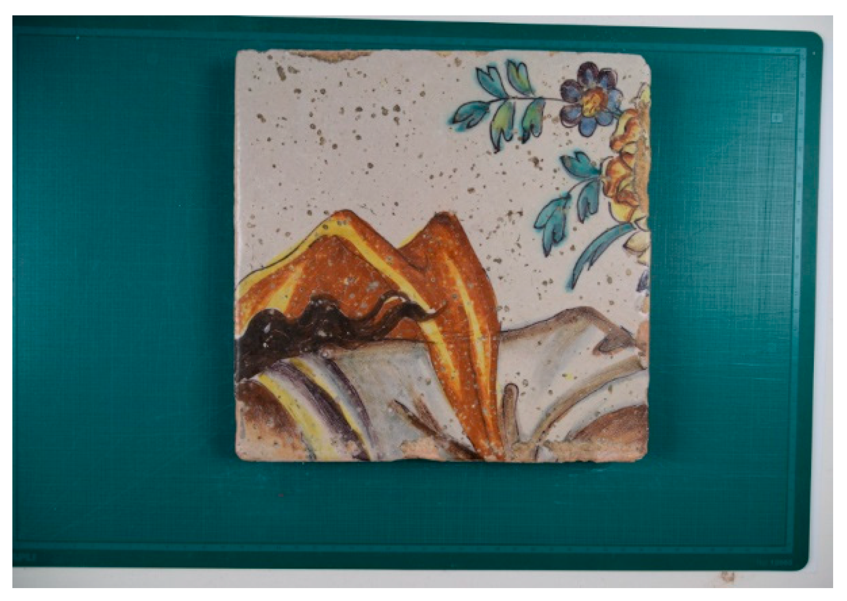
Figure 8.
Piece PA08 rectified and cropped.
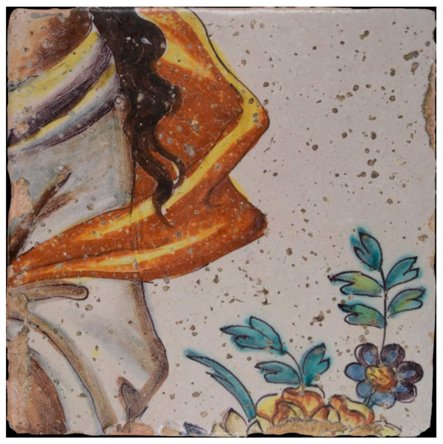
Figure 9.
Spring Panel.
Figure 10.
Chronos panel.
Figure 11.
Corner border panel.
Figure 12.
Layout of the restored pavement with the numbering of the pieces.
Figure 13.
Full design of the Four Seasons pavement.
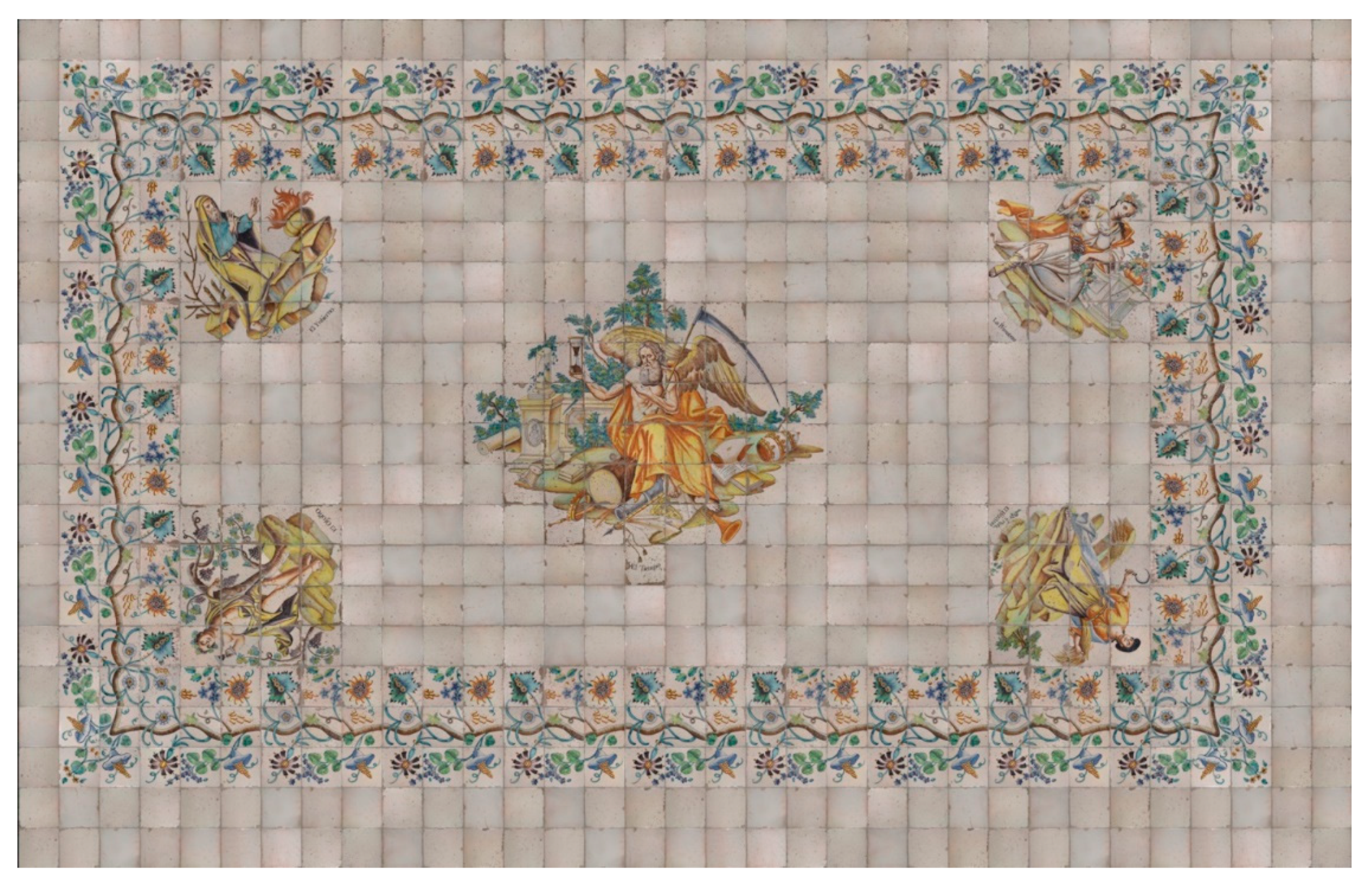
Figure 14.
(a) Cleaning of the point cloud of the Hall. (b) Colour point cloud of the Hall.
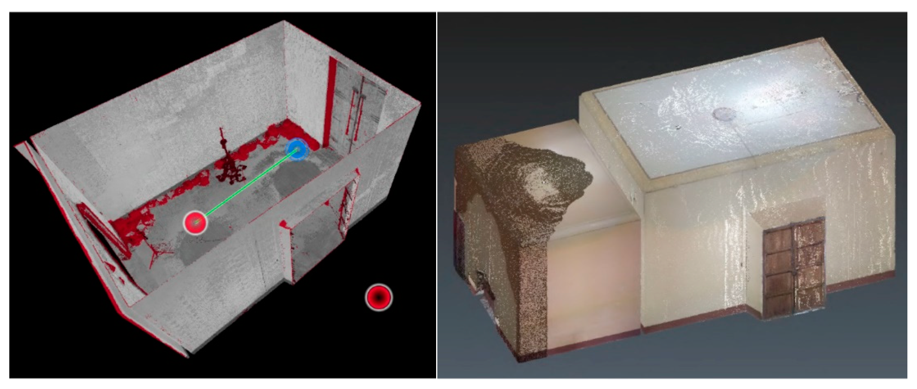
Figure 15.
3D mesh unrefined.
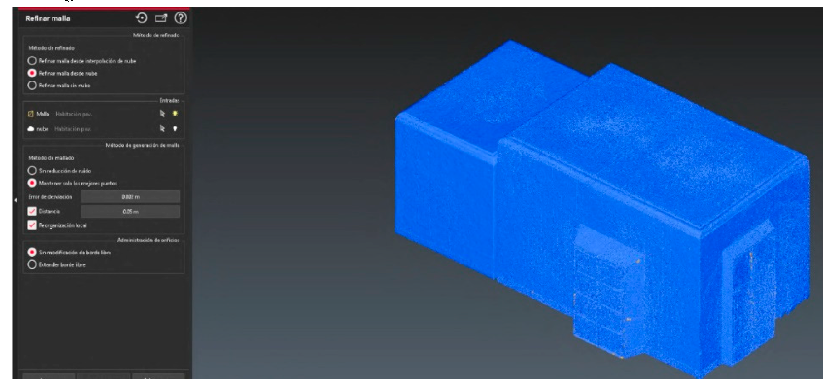
Figure 16.
Tight and refined mesh.
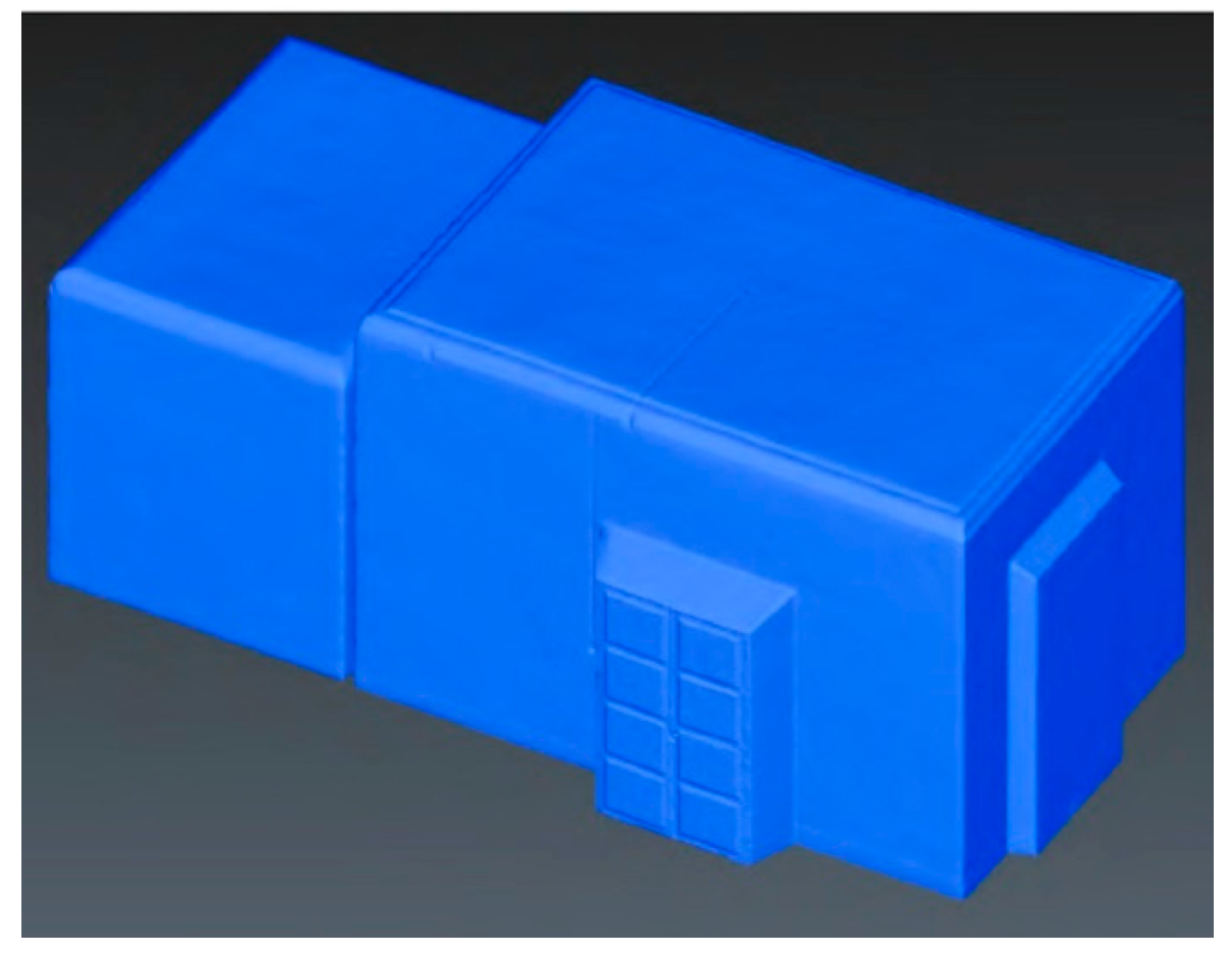
Figure 17.
(a) Original spherical image of the Hall. (b) Edited spherical image of the Hall.
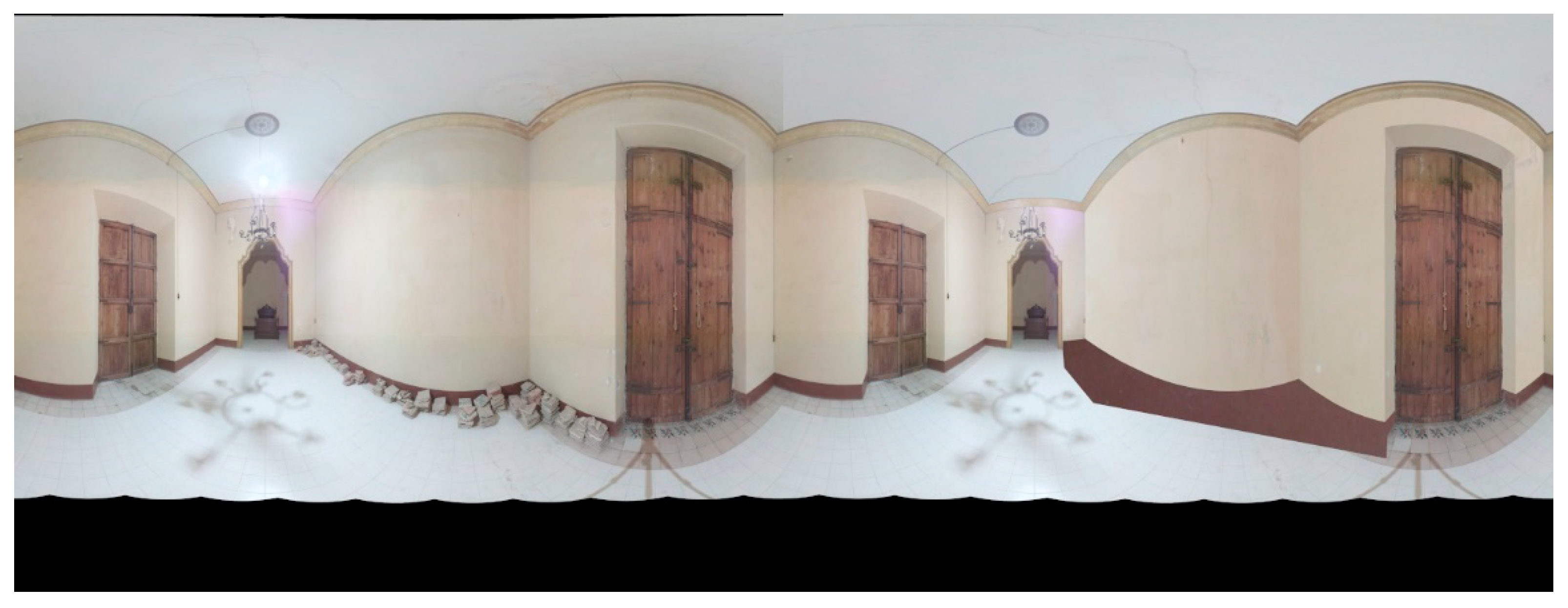
Figure 18.
Mesh textured using spherical images.
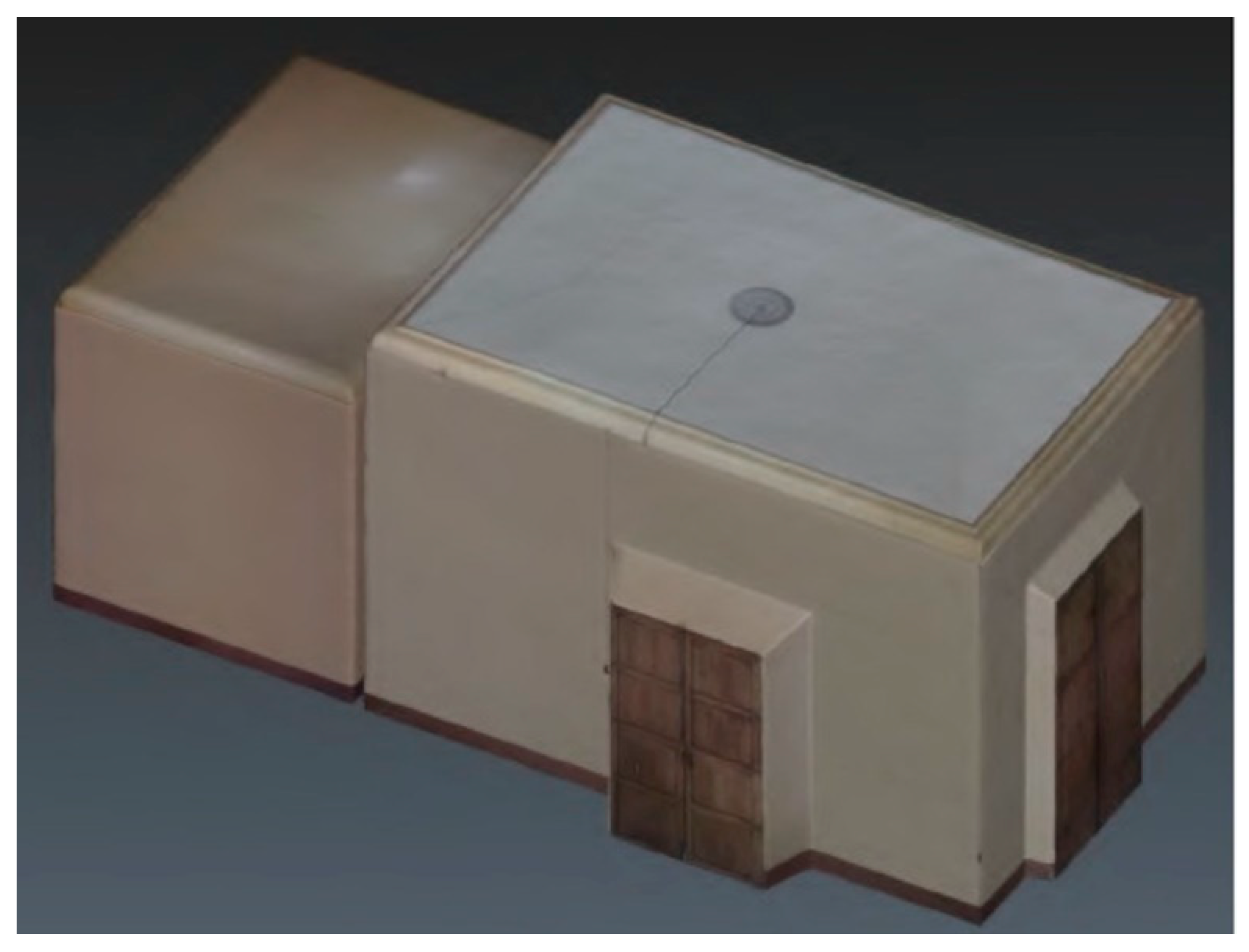
Figure 19.
"Texture adjustment" tool.
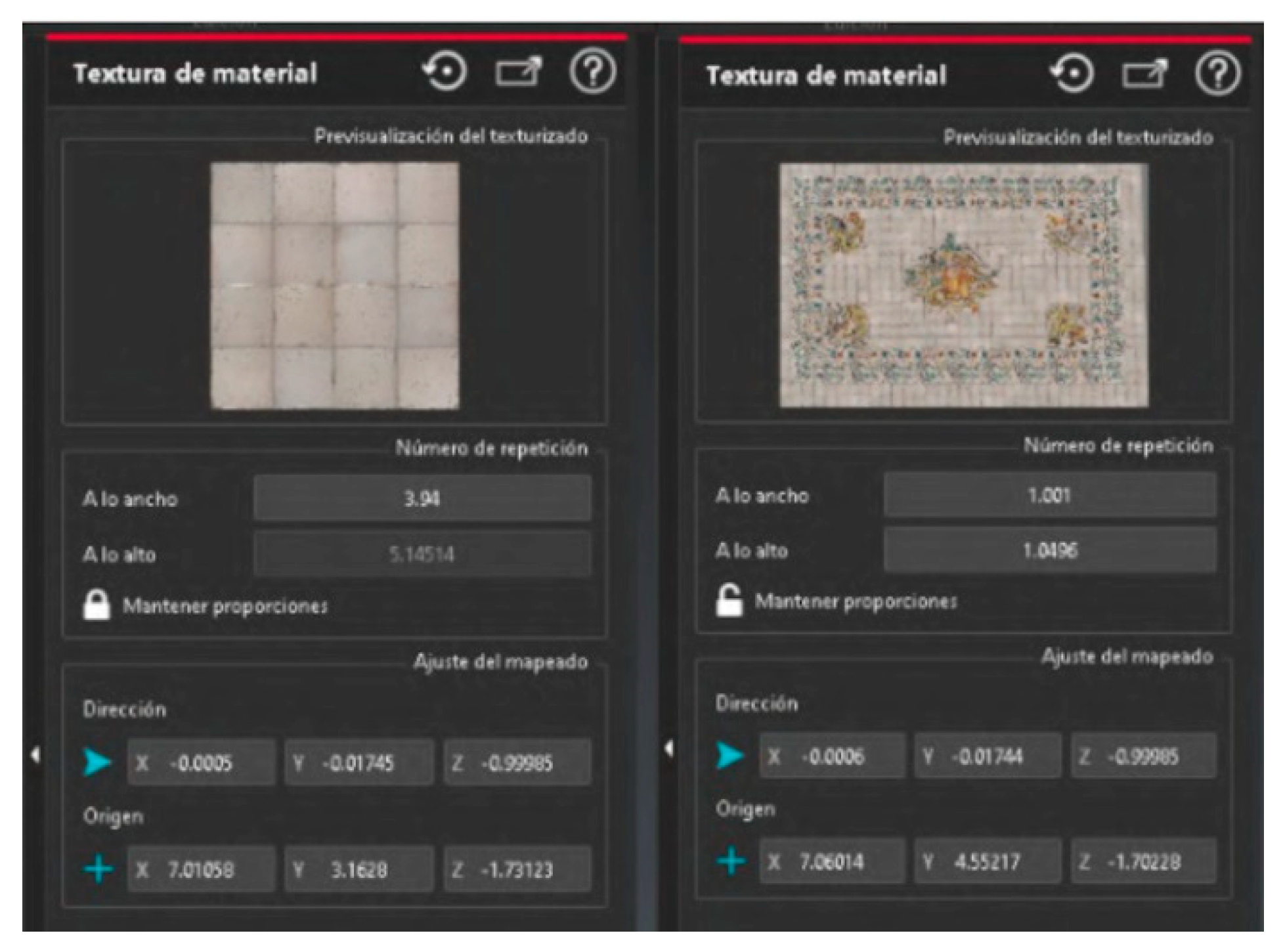
Figure 20.
Pavement texture adjusted to the mesh. floor view.
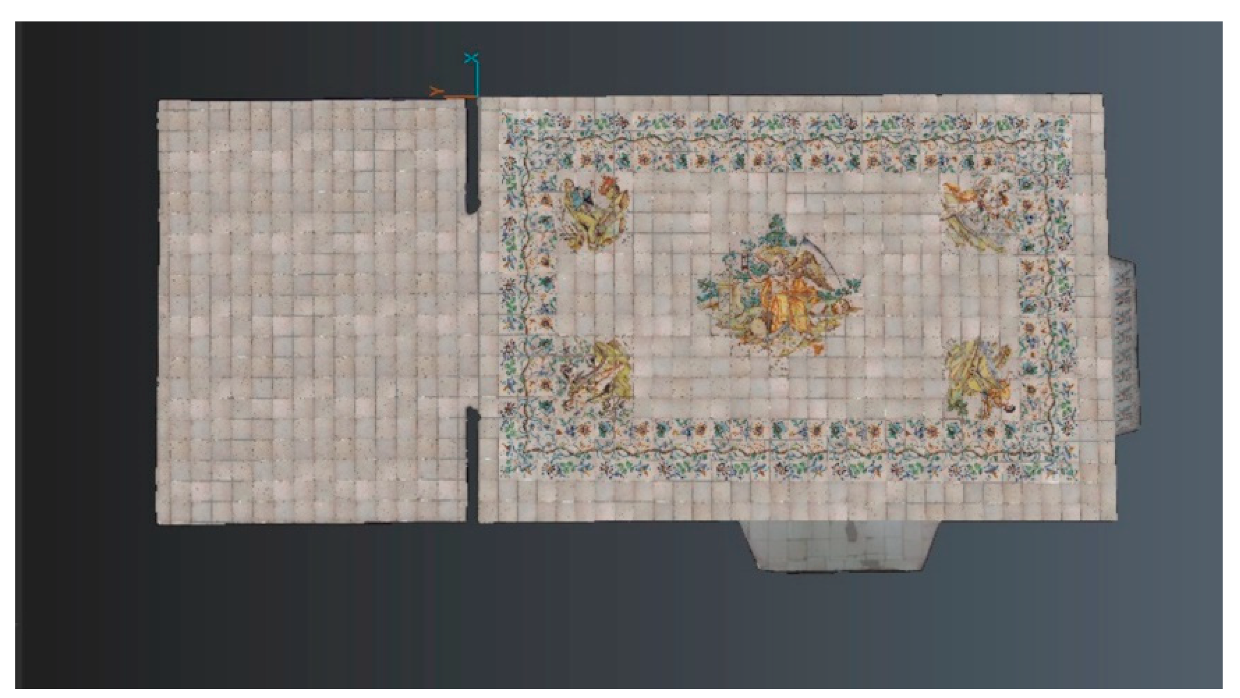
Figure 21.
Mesh textured using spherical images.
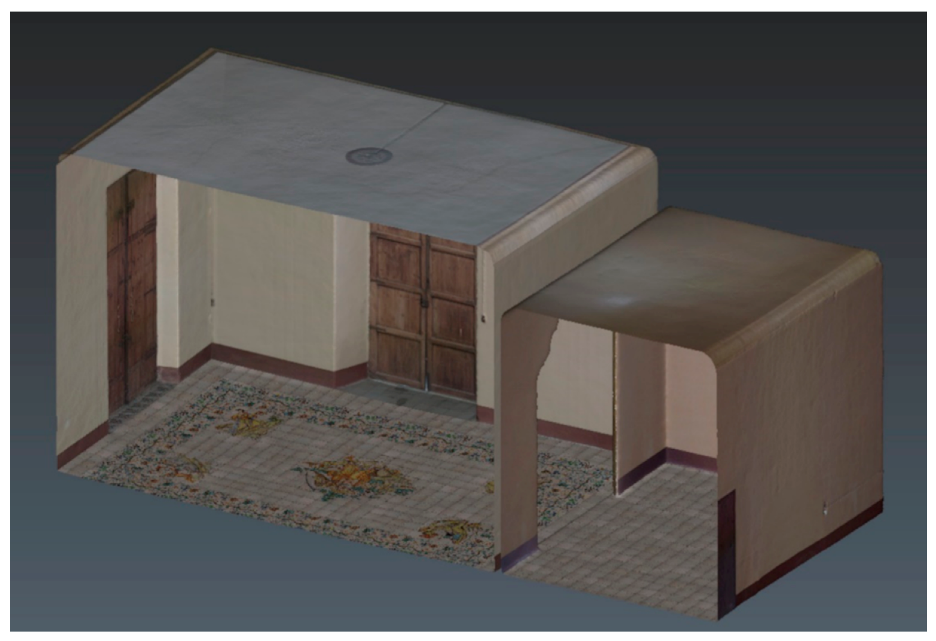
Figure 23.
Visualization of the Hall through VR.
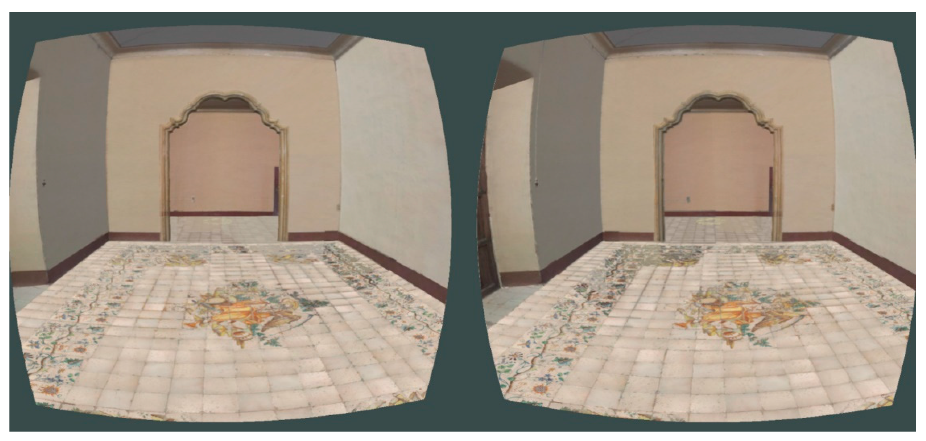
Figure 24.
View of the flooring in the 3D model of the Hall.
Disclaimer/Publisher’s Note: The statements, opinions and data contained in all publications are solely those of the individual author(s) and contributor(s) and not of MDPI and/or the editor(s). MDPI and/or the editor(s) disclaim responsibility for any injury to people or property resulting from any ideas, methods, instructions or products referred to in the content. |
© 2024 by the authors. Licensee MDPI, Basel, Switzerland. This article is an open access article distributed under the terms and conditions of the Creative Commons Attribution (CC BY) license (http://creativecommons.org/licenses/by/4.0/).
Copyright: This open access article is published under a Creative Commons CC BY 4.0 license, which permit the free download, distribution, and reuse, provided that the author and preprint are cited in any reuse.


