
Submitted:
20 June 2024
Posted:
21 June 2024
You are already at the latest version
Abstract
Efficient traffic flow management at intersections is vital for optimizing urban transportation networks. This paper presents a comprehensive approach to refining traffic flow by analyzing the capacity of roads and integrating fuzzy logic-based traffic light control systems. We were examining the capacity of roads connecting intersections, considering factors such as road vehicle capacity, vehicle speed, and traffic flow volume, through detailed mathematical modelling and analysis. Control is determined by the maximum capacity of each road segment, providing valuable insights into traffic flow dynamics. Building upon this capacity and flow analysis, the research introduces a novel Intelligent Traffic Light Controller (ITLC) system based on fuzzy logic principles. By incorporating real-time traffic data and lever-aging fuzzy logic algorithms, our ITLC system dynamically adjusts traffic light timings to optimize vehicle flow at two intersections. The paper discusses the de-sign and implementation of the ITLC system, highlighting its adaptive capabilities in response to changing traffic conditions. Simulation results are presented, demonstrating effectiveness of the ITLC system in improving traffic flow and re-ducing congestion at intersections. Furthermore, this research provides an analysis of the mathematical models used to calculate road capacity, offering insights into the underlying principles of traffic flow optimization. Through the simulation, we have validated accuracy and reliability of our controller.
Keywords:
Fuzzy Controller
; Traffic Light Controller
; Traffic Simulation
; Transportation
; Network
; SUMO
1. Introduction
Traffic control system is one of the key subsystems in the Intelligent Transport Systems (ITS) [1]. Smart vehicles, as well as smart infrastructure, are our main research areas [2], [3,4]. Traffic congestion is a pressing issue in urban areas globally, leading to increased travel time, fuel consumption, and environmental pollution. Efficient traffic signal control systems play a pivotal role in mitigating congestion and enhancing transportation efficiency. Over time, various methods and technologies have been developed to optimize traffic signal timings and improve traffic flow. Understanding the evolution of traffic signal control methods, from conventional fixed-time approaches to more adaptive and intelligent systems, is crucial for addressing the challenges posed by urban traffic congestion.
Traffic signal control methods, as outlined in recent studies, include conventional fixed-time control [1], adaptive control [2], fuzzy logic-based approaches [3,6,7], reinforcement learning (RL)-based methods [4,5,8,9], and fuzzy inference system (FIS)-based approaches [10,11]. Each method offers unique advantages and challenges in optimizing traffic signal settings and managing traffic flow.
Examination of the existing body of research provides insights into the strengths and limitations of each approach, as demonstrated in recent studies. It highlights their applicability in real-world traffic management scenarios. We have reviewed emerging trends and future directions in traffic signal control. Published research emphasizes the need for innovative solutions to address the complexities of modern urban transportation systems. Despite the advancements in traffic signal control systems, several gaps remain in the existing research. Fixed-time control systems, such as those initially developed in the mid-20th century, are inherently static and unable to adapt to real-time traffic conditions. These systems often struggle to handle varying traffic volumes and patterns, resulting in significant inefficiencies, especially during peak hours and under diverse traffic scenarios [1]. Adaptive traffic control systems like Sydney Coordinated Adaptive Traffic System (SCATS) dynamically adjust signal timings based on real-time traffic data. However, these systems are complex and costly to implement and maintain. Their effectiveness is highly dependent on the quality and accuracy of collected traffic data, which can be inconsistent, leading to potential reliability issues [2].
Fuzzy logic, as a powerful control systems approach, was introduced by Lotfi A. Zadeh, in the last century [5,6,7], but relatively recent, compared to digital control logic. Our research team is already using fuzzy logic approach in various science discipline [8,9].
Fuzzy logic-based traffic control systems offer a promising alternative by relying on expert knowledge to define rules that manage traffic flow. Nevertheless, the creation of accurate and comprehensive fuzzy rules is challenging. The performance of these systems can be inconsistent if the input data is highly variable, limiting their scalability and generalizability across different traffic conditions and intersection types [3,6,7].
Reinforcement learning (RL)-based methods have emerged as another innovative approach, requiring substantial computational resources and large amounts of training data to learn optimal policies. The real-time applicability of RL methods is often restricted by the need for continuous learning and adaptation, which can be computationally intensive and time-consuming [4,5,8,9].
Similarly, Fuzzy Inference Systems (FIS) like those using Mamdani models have proven effective in specific traffic scenarios. However, their scalability and integration into existing traffic management infrastructure remain limited. These systems may struggle to handle complex and dynamic urban traffic patterns, with performance potentially degrading as system complexity increases [10,11].
Our proposed fuzzy logic controller (FLC) aims to address some of these gaps by integrating the strengths of fuzzy logic with real-time traffic data to provide dynamic and adaptive traffic signal control. The key features of the novel FLC include definition of dynamic input variables, such as the number of vehicles in red and green lanes, and the waiting time of vehicles in red lanes. FLC constructs rule-based inference systems to map inputs to outputs through a set of fuzzy logic rules, encapsulating expert knowledge and empirical data about traffic flow dynamics. Efficient defuzzification converts fuzzy outputs into crisp values, determining precise control actions for traffic signals. This process ensures that the traffic signal control actions are both precise and effective in optimizing traffic flow. By addressing existing gaps, the proposed FLC offers a promising solution for dynamic and adaptive traffic signal control, potentially leading to reduced congestion and improved traffic flow in urban areas.
Traffic signal control is crucial for managing traffic flow and reducing congestion in urban areas. Over the years, various methods were proposed and implemented to optimize traffic signal settings. This literature review provides an overview of different traffic signal control methods, categorizing them based on their underlying principles and approaches.
Traditional traffic signal control methods, such as fixed timing and vehicle actuation, have long been used in traffic management systems [1]. These methods provide predetermined signal timings or adjust signals based on vehicle presence at intersections. However, they are limited in adaptability to changing traffic conditions and may lead to suboptimal traffic flow.
Adaptive control methods, like Split Cycle Offset Optimization Technique (SCOOT) and SCATS, respond to real-time traffic demands by adjusting signal timings accordingly [2]. These systems use fixed detector data to optimize signal settings but may suffer from limitations in handling dynamic traffic scenarios effectively. However, gaps exist in the literature concerning their implementation and performance. Firstly, these systems heavily rely on fixed detector data, potentially overlooking the need for advanced sensor technologies or data sources to enhance responsiveness and accuracy. Secondly, while effective in typical scenarios, they may not fully account for the complexities of dynamic traffic situations. Future research should explore innovative approaches for data integration and algorithm optimization to enhance their adaptability in diverse urban environments.
Fuzzy logic-based controllers offer an alternative approach, allowing for dynamic adjustments based on uncertain or imprecise inputs [3,6,7]. These controllers utilize fuzzy rules to optimize signal timings, considering factors such as traffic volume, congestion levels, and lane-specific data. By dynamically adjusting green light durations, fuzzy logic controllers aim to improve traffic flow and reduce congestion. Fuzzy logic-based controllers offer a dynamic approach to optimizing signal timings for improved traffic flow and congestion reduction. However, their current representation may overlook critical variables such as their adaptability to varying traffic scenarios. Additionally, inaccuracies in input data or deviations from predefined rules may affect their performance.
Recent advancements in deep reinforcement learning (DRL) have shown promise in optimizing traffic signal control systems [4,5,8,9]. RL-based methods learn optimal control policies through interaction with the environment, utilizing techniques like Deep Deterministic Policy Gradient (DDPG), Proximal Policy Optimization (PPO), and Deep Q-Networks (DQNs). These methods offer adaptability and performance improvements by learning from real-time traffic data and optimizing signal timings accordingly. However, current research overlooks challenges in practical implementation, such as computational complexity. There's a gap in understanding the constraints and limitations of DRL-based methods in real-world traffic management.
Fuzzy Inference System (FIS) based methods leverage fuzzy logic to dynamically adapt signal timings according to real-time traffic conditions [10,11]. These controllers integrate variables like traffic volume, queue length, and arrival flow to enhance traffic flow and alleviate congestion. Specifically, the Mamdani type FIS offers a structured approach to decision-making, utilizing fuzzy rules and linguistic variables, which renders it applicable to traffic systems facing unpredictable conditions. However, existing research may underestimate the challenges associated with integrating FIS-based controllers into extensive urban traffic networks, along with the potential performance decline as system complexity increases.
Comparative studies among various control methods illuminate the strengths and weaknesses of each approach [1,2,3,4,5,6,7,8,9,10,11]. RL-based methods exhibit significant enhancements in traffic flow and efficiency when compared to traditional fixed-time control and adaptive control methods [4,5,8,9]. Similarly, fuzzy logic-based controllers prove effective in reducing queue counts, waiting times, and overall congestion at intersections [6,7]. However, challenges persist in accurately modeling dynamic traffic scenarios and ensuring robust performance in real-world applications. Despite shedding light on the advantages and drawbacks of different control strategies, these comparative studies often overlook the integration challenges and scalability issues faced by RL-based and fuzzy logic-based approaches [1,2,3,6,7,8,9,10,11]. These methods may not fully address the complexities of dynamic traffic scenarios or ensure reliable performance in practical settings, creating gaps in understanding their implementation and effectiveness.
Recent advancements in intelligent transport systems (ITS) have significantly impacted the way urban traffic is managed, emphasizing the integration of smart vehicles and infrastructure. A study by Aldakkhelallah et al. [13] on public opinion in Saudi Arabia highlights the importance of societal acceptance and the perceived benefits of ITS developments. This underscores the need to consider public sentiment in the implementation of ITS projects.
Traffic flow optimization remains a critical area of research, with Rota and Simic [14] exploring various strategies to enhance freeway efficiency. Their work demonstrates the application of computational techniques to mitigate congestion, which is essential for improving travel times and reducing environmental impacts.
Todorovic et al. [15] provide a comprehensive scientometric and bibliometric review of the transition to autonomous and electric vehicles, offering valuable insights into current research trends and future directions. This review identifies key areas where further research is needed to support the widespread adoption of these technologies.
The public's perception of autonomous vehicles is also crucial, as detailed by Aldakkhelallah et al. [16]. Their research indicates that acceptance of autonomous vehicles depends on factors such as safety, reliability, and the perceived advantages over traditional vehicles. Addressing these concerns through public education and policy support is vital for successful integration.
Foundational works by Zadeh [17,19] and Bellman [18] on fuzzy logic and decision-making in fuzzy environments have paved the way for modern adaptive control systems. These principles are now applied in traffic management systems to handle the uncertainty and variability inherent in urban traffic. While these works provide a theoretical basis for fuzzy logic, they do not dive into the practical application of fuzzy logic in large-scale
Simic's study on cascaded fuzzy logic for adaptive cruise control [20] exemplifies the application of fuzzy logic in real-time traffic management. This approach enables dynamic adaptation to changing traffic conditions, enhancing both traffic flow and safety. Such systems are particularly relevant for autonomous vehicle technology and intelligent traffic signal control. The broader application of this approach to other traffic management scenarios, such as intersection control or freeway management, is not explored. The study also does not discuss the challenges of integrating fuzzy logic controllers with other ITS components.
Traffic signal control methods have evolved from conventional fixed-time approaches to more adaptive and intelligent systems. While traditional methods provide a baseline, adaptive control methods, fuzzy logic-based controllers, RL-based approaches, and FIS-based approaches offer enhanced adaptability and performance in managing dynamic traffic scenarios. Future research should focus on refining existing methods, addressing challenges, and integrating emerging technologies to further improve traffic management systems and alleviate urban congestion.
2. Materials and Methods
We have set up a traffic system with simulation that models two adjacent intersections equipped with traffic lights, each controlled by a separate fuzzy logic controller. The two intersections are positioned side by side, simulating a scenario where two neighboring junctions are present along a road network. At each intersection, we employ a fuzzy logic controller to manage traffic flow. These controllers consider inputs such as the number of vehicles in red and green lanes and the maximum waiting time in red lanes. The goal is to optimize traffic flow and reduce congestion by controlling the timing of traffic light changes.
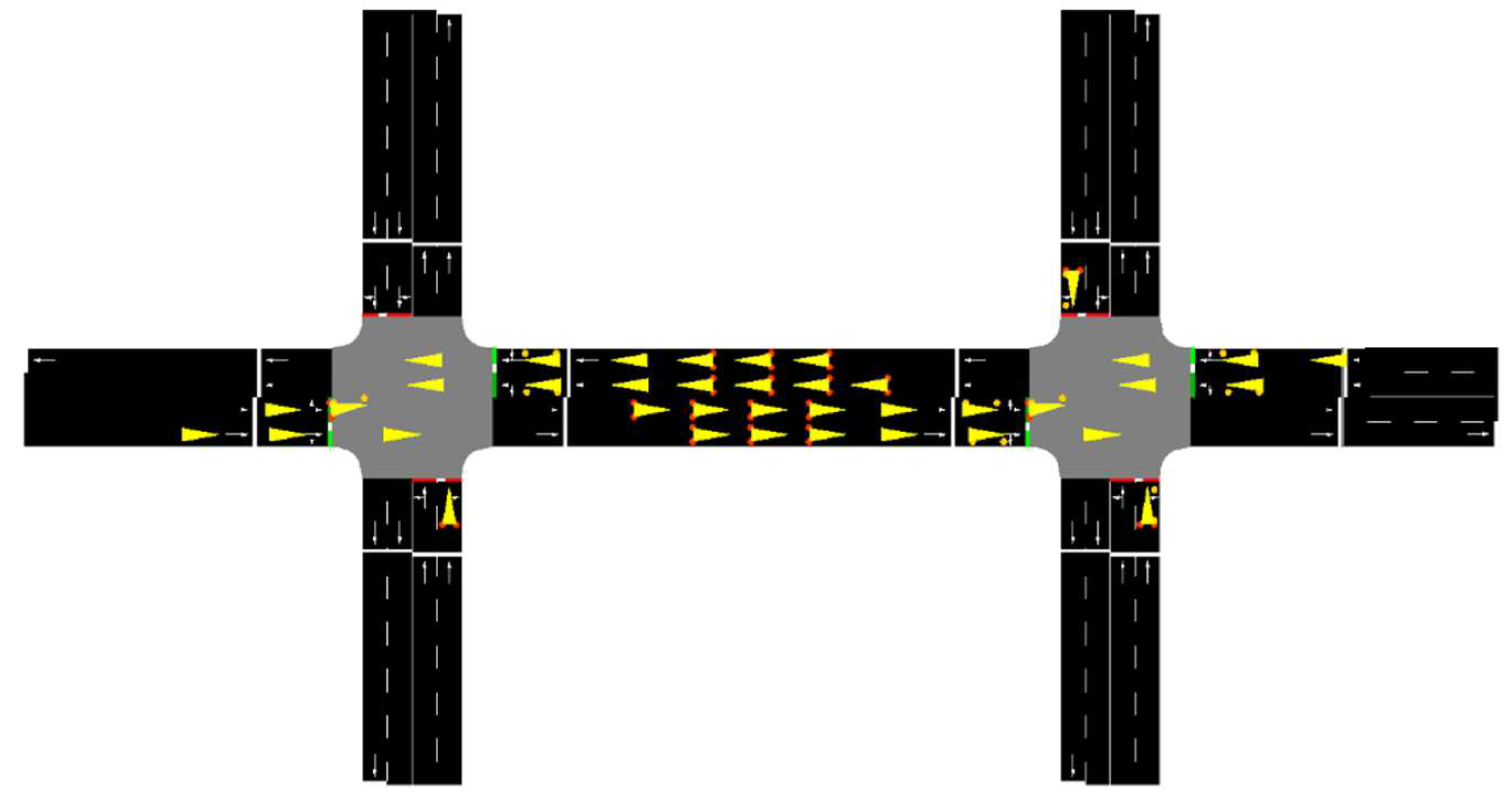
Figure 1.
An illustration of 2 interconnected traffic light intersections during a FIS-Sumo controlled simulation.
Figure 1.
An illustration of 2 interconnected traffic light intersections during a FIS-Sumo controlled simulation.
One unique aspect of our simulation is that the traffic lights at both intersections switch synchronously. This switching ensures coordination between the intersections, allowing for a smooth flow of traffic along the main horizontal road. Furthermore, priority is given to the road, which is the main thoroughfare, ensuring that it has an advantage over side roads. This prioritization is achieved by setting longer green phases for the main road, allowing for uninterrupted traffic flow along this crucial route. By implementing two fuzzy logic controllers working synchronously, and coordinating the traffic lights between adjacent intersections, our simulation aims to replicate real-world traffic management strategies and evaluate their effectiveness in improving traffic flow and reducing congestion.
The simulation models two adjacent intersections equipped with traffic lights, each controlled by a separate fuzzy logic controller. The two intersections are positioned side by side, simulating a scenario where two neighboring junctions are present along a road network. At each intersection, we employ a fuzzy logic controller to manage traffic flow. These controllers consider inputs such as the number of vehicles in red and green lanes and the maximum waiting time in red lanes. The goal is to optimize traffic flow and reduce congestion by controlling the timing of traffic light changes.
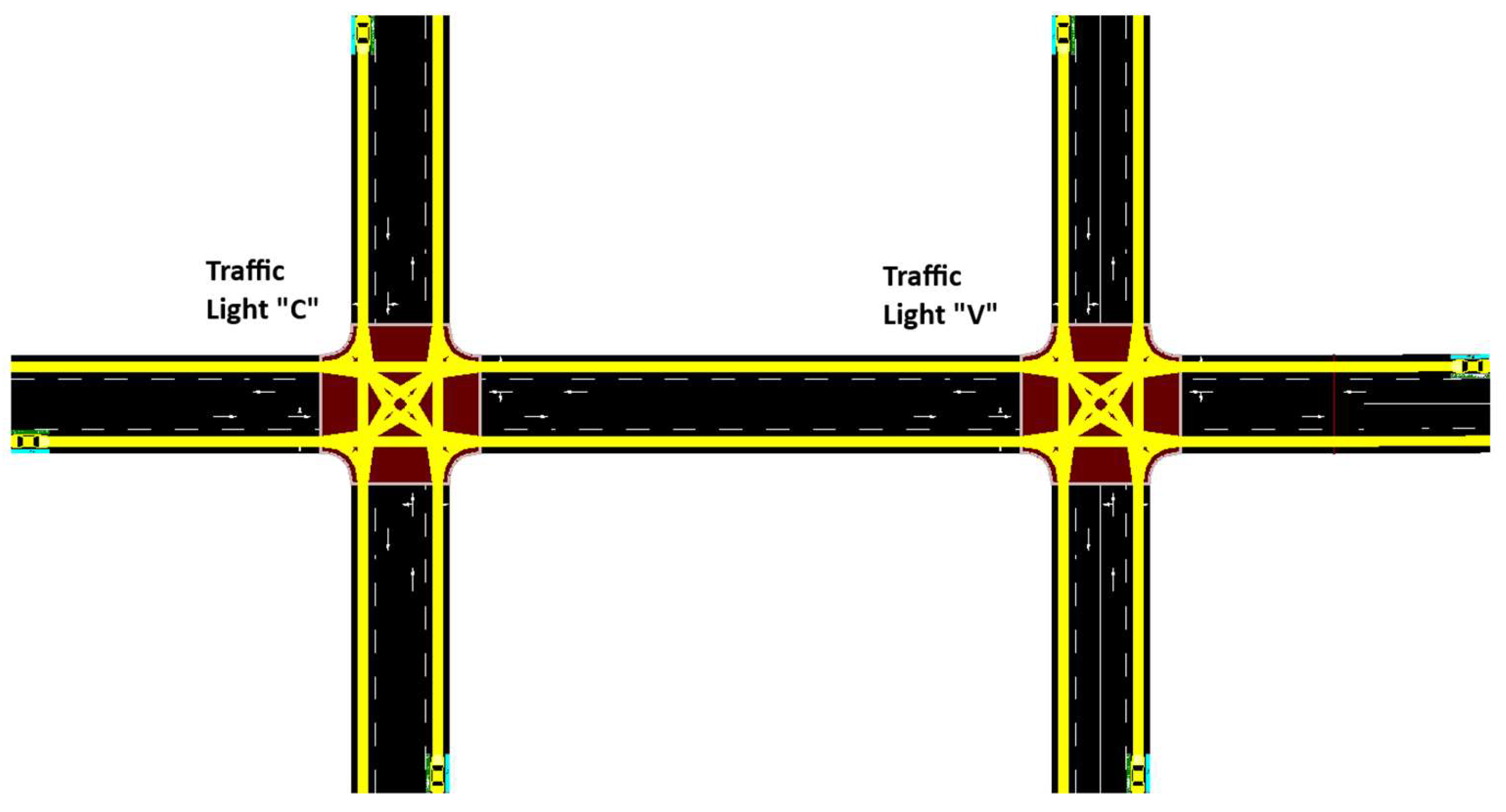
Figure 2.
An illustration of 2 interconnected intersections with 2 lanes in each direction implemented in SUMO.
Figure 2.
An illustration of 2 interconnected intersections with 2 lanes in each direction implemented in SUMO.
One unique aspect of our simulation is that the traffic lights at both intersections switch synchronously. This switching ensures coordination between the intersections, allowing for a smooth flow of traffic along the main horizontal road. This prioritization is achieved by setting longer green phases for the horizontal road, allowing for uninterrupted traffic flow along this crucial route.
In our research, the Simulation of Urban Mobility (SUMO) version 1.9.2 was utilized. SUMO is an open-source, highly portable, and microscopic traffic simulation package designed to handle large road networks. The simulation involves two intersections, each with two lanes in either direction, connected horizontally, as shown in the Figure 1. Traffic is generated to enter the simulation road network at all six lane entries, as shown in a snapshot of the setup in SUMO.
Traffic Control Interface (Traci) was used to integrate SUMO with the fuzzy logic controller. Traci facilitates communication between SUMO and the Python-based fuzzy controller, which is implemented using SciKit Fuzzy and NumPy libraries. This interface allows the simulation to send real-time traffic data to the fuzzy controller, such as the number of cars and their waiting times.
Fuzzy logic controller uses three inputs: the number of vehicles in the red lanes, the number of vehicles in the green lanes, and the maximum waiting time of vehicles in the red lanes. These inputs are processed by the fuzzy controller to evaluate the current traffic conditions. Fuzzy controller's outputs determine whether the traffic lights at either intersection should be toggled. By adjusting the traffic light timings based on real-time data, the system aims to improve traffic flow and reduce waiting times at the intersections.
Simulation runs for a specified duration of 1000 steps. During this period, vehicles are generated at a rate of [vehicles per hour] and introduced into the network at predefined locations such as A, B, etc. The types of vehicles, including their size and speed, are varied to reflect realistic traffic conditions, with speeds set to [Vehicle Speed Range] and sizes categorized as [Vehicle Size Categories]. The probability of vehicles changing lanes or turning at intersections is defined as [Probability Values].
To ensure robust statistical analysis, each simulation is repeated 10 times under identical conditions. The data collected from these repetitions are then analyzed to evaluate the performance of the fuzzy logic controller.
In a standard SUMO simulation, default settings govern the behavior and characteristics of vehicles within the simulated environment. The default vehicle type, typically referred to as "passenger" or "passenger car," embodies the archetype of a typical car found on city streets. With a length averaging between 4 to 5 meters and a width of around 2 meters, these vehicles reflect the dimensions of everyday passenger cars. Their speed parameters, often set within a range of 10 to 20 meters per second (36 to 73 km/hour), mirror the typical velocities encountered in urban traffic. Additionally, the default behavior includes the probability of lane changing, capturing the dynamic nature of traffic flow, and a standard turning behavior at intersections, enabling vehicles to navigate left, right, or straight-ahead based on the road network layout and traffic signals [12]. The default setting for lane changing behavior is typically governed by the lane change model specified in the simulation configuration. By default, SUMO uses the "LC2013" lane change model, which is based on the Intelligent Driver Model (IDM) and the MOBIL lane change model. These default settings provide a foundational framework for simulating realistic traffic scenarios within SUMO, facilitating nuanced analysis and experimentation in urban mobility research and planning.
To ensure robust statistical analysis, each simulation is repeated 10 times under identical conditions. The data collected from these repetitions is then analyzed to evaluate the performance of the controller.
The fuzzy logic controller was implemented using SciKit Fuzzy (skfuzzy). The fuzzy logic controller accepts three inputs: the number of vehicles on the red lanes (no_vehicle_red_lane), the number of vehicles on the green lanes (no_vehicle_green_lane), and the maximum waiting time of vehicles on the red lanes (waiting_time_red_lane).
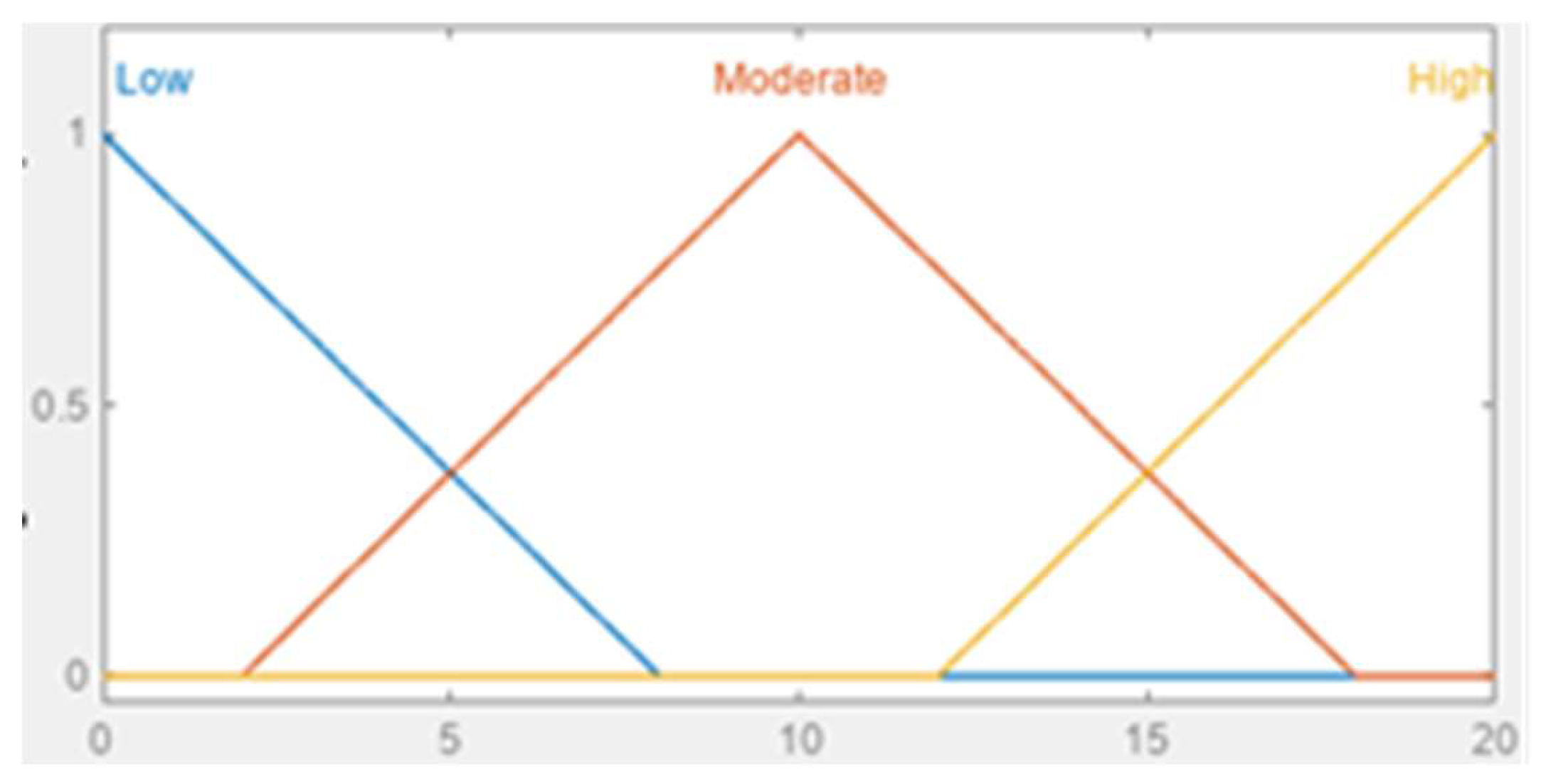
We defined the number of vehicles using an array of integers from 0 to 22. Then we used three types of membership functions to define the memberships. Values from 0 to 8 were defined as "Low" using a z-shaped membership function (zmf). Values from 2 to 18 were defined as "Moderate" using a triangular membership function (trimf). Values from 12 to 20 were defined as "High" using an s-shaped membership function (smf).
Figure 3.
Memberships functions representing the number of vehicles in the Red/Green Lane.
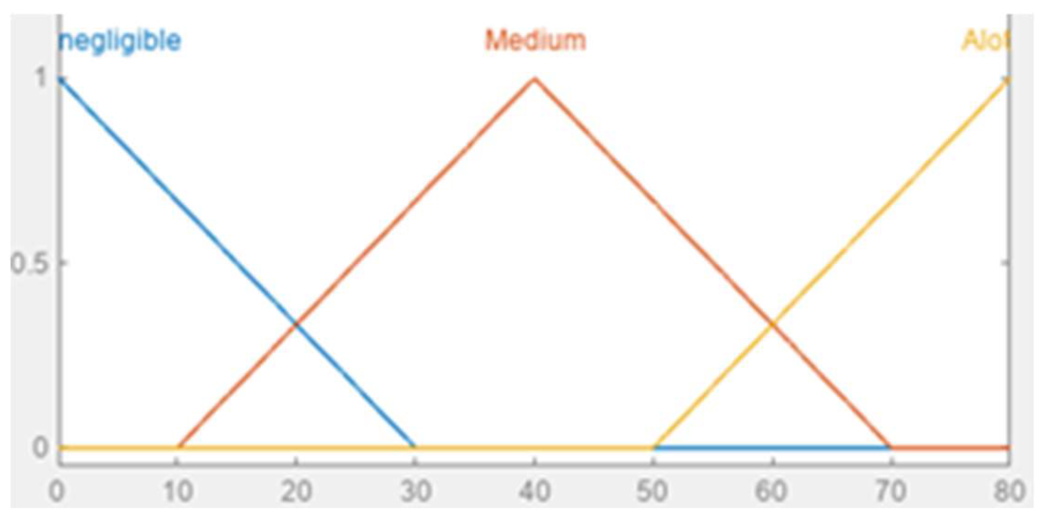
Waiting time was defined using an array of integers from 0 to 80. From our network, we found that the maximum waiting time of vehicles before the traffic light switches falls within the range of 0 to 80. We used three types of membership functions to define the memberships. Waiting times from 0 to 30 were defined as "negligible" using a z-shaped membership function (zmf). Waiting times from 10 to 70 were defined as "Medium" using a triangular membership function (trimf). Waiting times from 50 to 80 were defined as "Alot" using an s-shaped membership function (smf).
Figure 4.
An illustration of fuzzy memberships functions representing the Waiting Time of vehicles in red lane.
Figure 4.
An illustration of fuzzy memberships functions representing the Waiting Time of vehicles in red lane.
The output of the fuzzy logic controller is a value between 0 and 1, implemented by passing an array containing 0 and 1 as the consequent. If the output is 0, then the traffic light is “okay”; if it is 1, then it needs switching. The output is defined using two membership functions: "okay" with a z-shaped membership function (zmf) from 0 to 0.5, and "need-switching" with an s-shaped membership function (smf) from 0.5 to 1.
Figure 5.
An illustration of fuzzy memberships functions representing the Traffic Light Signal membership function.
Figure 5.
An illustration of fuzzy memberships functions representing the Traffic Light Signal membership function.
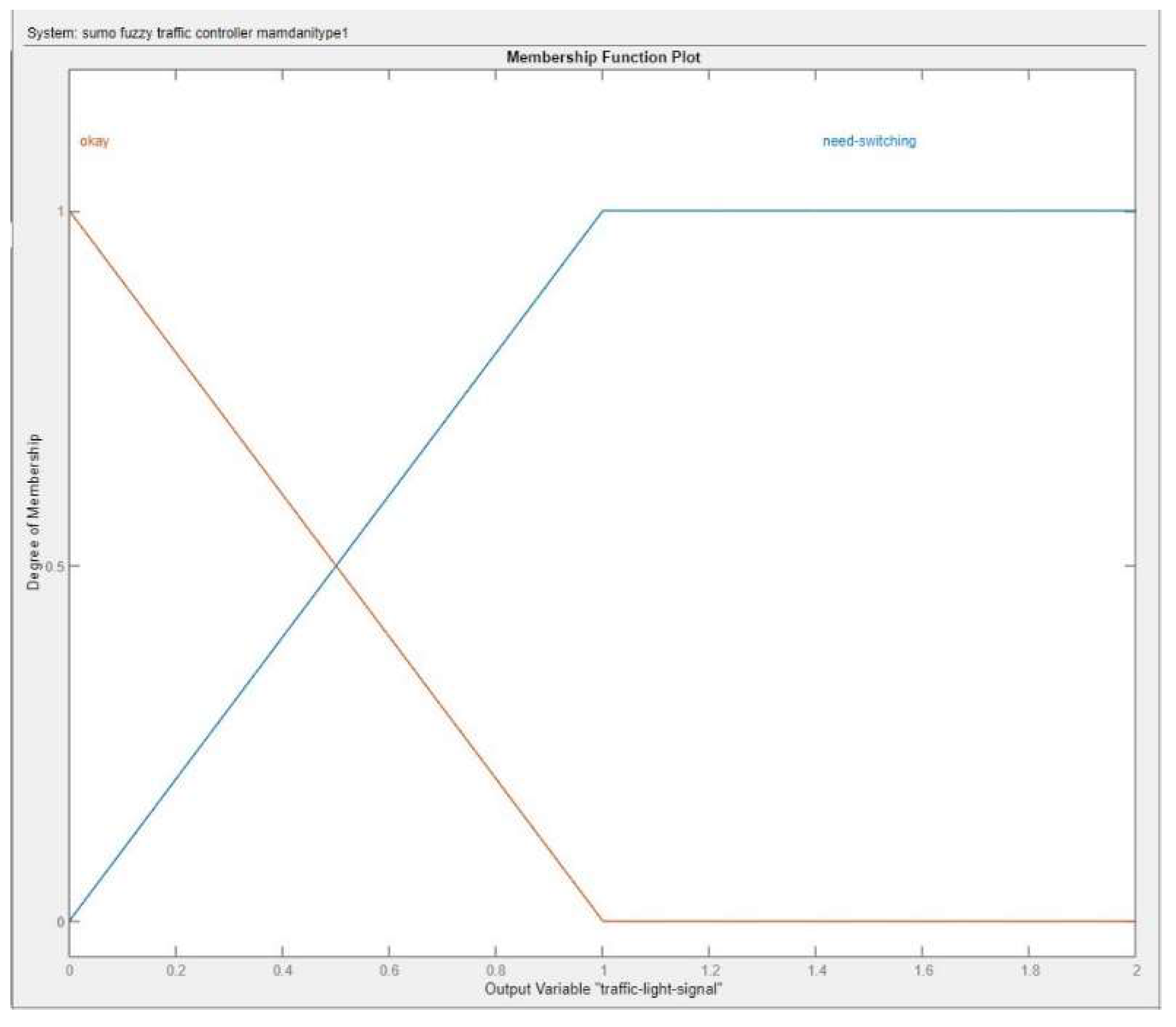
These sets of antecedents and consequents were grouped into fuzzy rules used to create the control system. The control system was then simulated and used to compute outputs based on the three inputs. The output of the fuzzy logic controller is a value from 0 to 1. The output zero indicates that the traffic controller is okay, and the value one means that the controller needs switching. When running the simulation, the output usually falls between 0.3 and 0.7, so we set a bar at 0.5. If the output is below 0.5, the traffic light will not be changed; otherwise, it would be switched.
Based on the evaluation of the fuzzy logic controller implemented in the provided code, it can be inferred that a more intelligent traffic light control system holds the potential to enhance throughput at intersections and diminish overall traffic congestion. Typically, prioritizing certain vehicles entails imposing additional waiting time on others, termed as "unprioritized" vehicles. However, in this project, no such delay was observed for unprioritized vehicles. Consequently, the average waiting time for unprioritized vehicles decreased, reduction in their average waiting time. Furthermore, there was a notable increase in the average number of moving vehicles within the intersection, accompanied by a reduction in the number of vehicles halted by traffic signals.
Algorithm 1. FLC Control algorithm Pseudocode
| Algorithm 1: Interaction Between Simulator and Fuzzy Controller |
| Input: T, τ, λ, ν_range, σ_categories, p_lane_change, p_turn Output: Traffic flow and waiting time statistics Initialize simulator Initialize fuzzy controller Define road network and entry points Generate vehicles at rate λ for t = 0 to T do if t mod τ == 0 then lanes_currently_moving, lanes_stopped_by_light ← getLaneLists(lanes_in_D1B2, lanes_in_G2H1, trafficLightID) vehicles_in_red_lanes ← getVehiclesIn Lane(lanes_stopped_by_light) vehicles_in_green_lanes ← getVehiclesInLane(lanes_cur rently_mov ing) N_r ← len(vehicles_in_red_lanes) N_g ← len(vehicles_in_green_lanes) W_max ← getMaxWaitingTime(vehicles_in_red_lanes) output ← fuzzyControllerFunction(N_r, N_g, W_max) if output ≥ θ then toggleTrafficLights(trafficLightID) end if end for closeSimulator() |
The Algorithm 1 pseudocode outlines the interaction between a traffic simulation system and a fuzzy logic controller to manage traffic flow at intersections. Initially, the simulator and fuzzy controller are initialized, and the road network and entry points are defined. Vehicles are generated at a specified rate to enter the network. The main simulation loop runs from time t=0 to t=T. At every interval τ, the simulator updates the number of vehicles on red and green lanes (Nr and Ng) and the maximum waiting time on the red lanes (Wmax). These parameters are passed to the fuzzy controller, which processes them and returns an output. If the output exceeds a predefined threshold θ, the traffic lights are toggled. The simulator then proceeds to the next simulation step, and data is collected for analysis. After completing the simulation, the system closes, the collected data, and the results are outputted.
Figure 6.
Control Flow Chart.

The flow chart given in the Figure 5 outlines the process for a fuzzy logic-based traffic control simulation. The simulation begins with initialization, setting the step count to zero. The system continuously checks the traffic light state, collecting data on vehicles in both green (moving) and red (stopped) lanes. Depending on the traffic light ID, it determines which lanes are moving or stopped. The core of the simulation runs in a loop until 1000 steps are reached, during which the system applies a Fuzzy Inference System (FIS) to control the traffic lights based on the real-time vehicle data. Every n step, the traffic lights may be toggled according to fuzzy logic rules. This dynamic approach aims to optimize traffic flow by adjusting signals based on current conditions, thereby reducing vehicle waiting times. The simulation concludes once the step count reaches nmax, effectively ending the process. This flow chart demonstrates a structured methodology for enhancing traffic management using fuzzy logic. Fuzzy logic controller (FLC) was implemented in Python using the scikit-fuzzy library, a powerful tool for fuzzy logic systems. This implementation involved several key steps. Firstly, the input and output variables were defined, including linguistic terms and their associated membership functions. For example, input variables such as 'no_vehicle_red_lane' and 'waiting_time_red_lane' were defined with terms like 'Low', 'Moderate', and 'High', each with appropriate membership functions. Next, fuzzy rules were established to govern the system's behavior, specifying how inputs should be mapped to outputs. These rules were constructed based on expert knowledge of traffic flow dynamics. Once the rules were defined, a control system was created to simulate the FLC's behavior using the Control System class provided by scikit-fuzzy. Finally, the controller was integrated into the larger traffic simulation environment, interacting with the SUMO traffic simulator via the TraCI interface. This implementation allows for real-time traffic control decisions based on fuzzy logic principles, offering an effective and adaptive solution for managing complex traffic scenarios.
3. Results
Figure 7 presents comparation the average vehicle waiting times at red lights between two different traffic control strategies: a SUMO fixed-time traffic controller and a fuzzy logic traffic controller. The results indicate that the fuzzy logic traffic controller significantly reduces the average waiting time at red lights compared to the fixed-time controller. Specifically, the average waiting time with the fuzzy logic controller is much lower, demonstrating its effectiveness in dynamically adjusting traffic light phases based on real-time traffic conditions. This reduction in waiting time likely leads to smoother traffic flow and decreased congestion, highlighting the advantages of using fuzzy logic for adaptive traffic management.
Error! Reference source not found. compares the performance of two traffic control systems: a fuzzy logic-controlled traffic system and a fixed time-controlled traffic system, over a series of 1000 time steps. The y-axis represents the waiting time of vehicles, while the x-axis represents the time steps.
The fuzzy logic-controlled traffic, depicted by the blue line, consistently shows lower average vehicle waiting times compared to the fixed time-controlled traffic, represented by the orange line. Throughout the 1000-time steps, the waiting times for the fixed time-controlled traffic demonstrate a recurring pattern of sharp increases, indicating periods where vehicles experience significant delays. These peaks can reach over 1200 seconds, suggesting that the fixed time system is less efficient in managing varying traffic conditions.
In contrast, the fuzzy logic-controlled traffic exhibits a more stable pattern with smaller and less frequent peaks. This indicates that the fuzzy logic system is more effective in adapting to changing traffic conditions, thereby reducing the overall waiting time for vehicles. The ability of the fuzzy logic system to maintain lower waiting times is evident, as it avoids the extreme delays observed with the fixed time control.
Overall, the graph highlights the superior performance of the fuzzy logic traffic controller in minimizing vehicle waiting times, thus demonstrating its effectiveness in enhancing traffic flow and reducing congestion. This adaptive approach allows for more responsive traffic management, aligning closely with real-world traffic dynamics and improving overall efficiency.
4. Discussion
To achieve optimal results in our traffic control system, fine-tuning of the fuzzy logic controller was essential. One crucial aspect of this fine-tuning process was determining an appropriate threshold value to trigger traffic light phase changes. This threshold value significantly influences the frequency and timing of phase changes, thereby directly impacting traffic flow efficiency. To determine the optimal threshold value, a series of trials were conducted, varying the threshold from 0.30 to 0.60. Each trial was evaluated based on its ability to improve traffic flow and reduce congestion, as shown in the Table 1.
Threshold values of 0.30 and 0.35 both resulted in identical average waiting times of approximately 72,252 seconds, with 48 signal changes and an average vehicle speed of around 16.65 km/h. A slight improvement is observed at a threshold value of 0.40, where the average waiting time decreases to 71,470 seconds, with 46 signal changes and a marginal increase in vehicle speed to 16.72 km/h.
At a threshold value of 0.45, the average waiting time increases to 84,246 seconds, while the number of signal changes drops to 33, leading to an improved average vehicle speed of 18.30 km/h. However, further increasing the threshold value to 0.50 and 0.60 results in significant increases in average waiting times (246,974 and 206,403 seconds, respectively) and a notable reduction in the number of signal changes (19 and 0, respectively). Despite the higher waiting times, these higher thresholds correspond to higher average vehicle speeds of approximately 28.99 and 28.88 km/h.
The data suggests that lower threshold values (0.30 to 0.40) result in more frequent signal changes and lower vehicle speeds, while higher threshold values (0.50 and 0.60) reduce the number of signal changes but at the cost of increased waiting times. The threshold value of 0.45 appears to strike a balance, achieving moderate waiting times, a reasonable number of signal changes, and improved vehicle speeds. This balance indicates that 0.45 is a potentially optimal threshold for efficient traffic management using fuzzy logic control.
The trials revealed that the most effective threshold value was 0.45. At this threshold, the controller demonstrated a balanced response, effectively managing traffic flow without causing unnecessary phase changes. Lower threshold values tended to make the controller overly sensitive, resulting in frequent and sometimes unnecessary phase changes, leading to reduced efficiency and increased driver frustration. Conversely, higher threshold values made the controller less responsive, causing delays in adapting to changing traffic conditions and potentially worsening congestion.
By carefully analyzing the outcomes of these trials, we were able to fine-tune the fuzzy logic controller to achieve optimal performance in our traffic control system. This highlights the importance of iterative testing and refinement in designing effective traffic management solutions.
Effective traffic management relies on carefully timed adjustments to traffic light control. In this section, we explore the rationale behind selecting an update interval of 40 simulation steps for our traffic light control system. By choosing this interval, we aim to strike a balance between responsiveness and stability, simulating real-life traffic scenarios while optimizing traffic flow and minimizing disruptions.
The decision to update the traffic light control every 40 simulation steps was a choice made to establish a balance between responsiveness and stability. This interval was carefully selected to align with real-life scenarios, where frequent traffic light changes can disrupt traffic flow and increase driver frustration. By updating the traffic light control every 40 steps, we aim to achieve less frequent switching of traffic lights. This approach mirrors real-life traffic management strategies, where traffic light changes are not made impulsively but rather in response to significant changes in traffic conditions.
Choosing an interval of 40 seconds allows the traffic light control system to adapt to evolving traffic patterns without excessively frequent changes. This helps in maintaining smoother traffic flow and reducing the likelihood of unnecessary disruptions. By emulating real-life traffic scenarios, our simulation provides a more accurate representation of traffic dynamics, enabling us to evaluate the effectiveness of our control strategies in a manner that aligns with real-world conditions.
Table 2 illustrates the average vehicle waiting times at red lights using two different types of traffic controllers: the SUMO Fixed Time Traffic Controller and the Fuzzy Logic Traffic Controller. Across various conditions, the SUMO Fixed Time Traffic Controller consistently resulted in a waiting time of 400 seconds. In contrast, the Fuzzy Logic Traffic Controller demonstrated more variability and generally shorter waiting times, except at the highest update interval. For instance, with traffic light updates at 35 seconds and 40 seconds, the Fuzzy Logic Traffic Controller had an average waiting time of 250 seconds, significantly lower than the fixed controller. As the update intervals increased, the waiting time for the Fuzzy Logic Traffic Controller also increased, with 300 seconds at a 45-second update, 370 seconds at a 50-second update, and eventually matching the fixed controller at 400 seconds for a 60-second update.
Based on this data, the choice to use a 40-second update interval in the code is justified because it offers the optimal balance between efficiency and performance. At 40 seconds, the Fuzzy Logic Traffic Controller achieves a significant reduction in waiting times (250 seconds) compared to the fixed time controller, maximizing the benefits of the Fuzzy Logic system while maintaining stability. This interval ensures minimal vehicle wait times without the diminishing returns observed at longer update intervals, making it the most efficient option among the tested scenarios.
In addition to the fuzzy logic controllers managing traffic light timings, we fine-tuned the traffic flows entering the two intersections in our SUMO simulation. These adjustments were made to prevent gridlocks and ensure that the roads do not reach full capacity, thus maintaining a smooth flow of traffic.
By carefully adjusting the traffic flows, we aim to replicate real-world traffic conditions where road capacities are not exceeded, preventing congestion and ensuring efficient movement of vehicles. This involved balancing the inflow of vehicles into each intersection, considering factors such as the number of lanes, road capacities, and expected traffic volumes.
Through iterative adjustments and simulation runs, we optimized the traffic flows to maintain a steady flow of vehicles without overwhelming the road network. This fine-tuning process is crucial for creating a realistic simulation environment that accurately reflects traffic conditions in urban areas. Combining the fine-tuned traffic flows with the fuzzy logic controllers for traffic light management allows us to comprehensively evaluate the effectiveness of our traffic management strategies in minimizing congestion and improving traffic flow.
The proposed study focuses on addressing key limitations in existing intelligent traffic management systems by integrating advanced fuzzy logic controllers. Firstly, ensuring high-quality and real-time traffic data is critical. The proposed system aims to enhance data collection accuracy and mitigate potential delays by employing robust sensor networks and advanced data processing techniques. Secondly, the proposed system aims to bridge the gap between simulation environments and real-world traffic scenarios. By incorporating unpredictable factors such as driver behavior, weather conditions, and road incidents into the simulation models, the study seeks to provide a more accurate representation of real-world traffic conditions.
5. Conclusions
This paper presents a comprehensive study on the implementation and evaluation of an Intelligent Traffic Light Controller (ITLC) using fuzzy logic to optimize urban traffic flow. By integrating real-time traffic data and leveraging fuzzy logic algorithms, the ITLC system dynamically adjusts traffic light timings to improve vehicle flow at intersections. The simulation results demonstrate that the fuzzy logic-based controller significantly reduces average vehicle waiting times compared to the traditional fixed-time traffic controller. Specifically, the fuzzy logic controller effectively adapts to changing traffic conditions, maintaining lower waiting times, and avoiding the extreme delays observed with the fixed-time controller.
The study underscores the potential of fuzzy logic systems in enhancing traffic management, reducing congestion, and improving overall urban transportation efficiency. Future research should focus on additional refining these systems, considering factors such as mixed vehicle fleets and advanced data integration to verify and enhance the performance of traffic control algorithms. Intelligent traffic control systems are crucial subsystems in the future ITS.
Author Contributions
Conceptualization, F.Z., C.T.C. and M.S.; methodology, F.Z., C.T.C. and M.S.; validation, F.Z., C.T.C.; formal analysis, F.Z., C.T.C. and M.S.; investigation, F.Z., C.T.C. and M.S.; conducting reviews C.T.C. and M.S.; data curation, F.Z.; writing original draft preparation, F.Z.; writing review and editing, C.T.C. and M.S.; supervision C.T.C. and M.S. All authors have read and agreed to the published version of the manuscript.
Funding
This research received no external funding.
Acknowledgments
The first author, Firas Zahwa, acknowledges The Australian Postgraduate Awards (APA) scholarship, funded by the Australian Federal Government, for the support in the study and research in traffic management.
Conflicts of Interest
The authors declare no conflicts of interest.
References
- Webster, F.V. Traffic Signal Settings. Road Research Technical Paper No. 39. H.M. Stationery Office, London, UK, 1958.
- SCATS (Sydney Coordinated Adaptive Traffic System). Available online: https://www.swarco.com/solutions/urban-traffic-management-control-systems/scats (accessed on 15 May 2024).
- Rao, B.S., Swathi, D., Naresh, B. Traffic Signal Control Using Fuzzy Logic. International Journal of Advanced Engineering Research and Science, 2017, 4(7), 219–227.
- Li, X., Wang, D., Cao, Z., Yu, W. Deep Reinforcement Learning for Intelligent Traffic Signal Control. IEEE Transactions on Intelligent Transportation Systems, 2019, 20(9), 3362–3372.
- Arel, I., Liu, C., Urbanik, T., Kohls, A.G. Reinforcement Learning-Based Multi-Intersection Traffic Signal Control. In Proceedings of the 2007 IEEE Symposium on Computational Intelligence in Multi-Criteria Decision-Making, Honolulu, HI, USA, 1–5 April 2007.
- Akhavan Rezai, E., Akhavan Rezai, E., Jahangiri, P. Traffic Light Control Using Fuzzy Logic. International Journal of Computer Applications, 2013, 77(13), 19–23.
- Chen, Z., Li, J., Liu, M., Jin, X. PressLight: Learning Max-Pressure Control to Coordinate Traffic Signals in Arterial Network. In Proceedings of the 28th International Joint Conference on Artificial Intelligence (IJCAI), Macao, China, 10–16 August 2019.
- Abiodun, O.I., Adewumi, A.O., Odetunmibi, O.A. Traffic Signal Control: A Reinforcement Learning Approach. In Proceedings of the International Conference on Computational Science and Its Applications, Fukuoka, Japan, 1–4 July 2019.
- Eom, M., Kim, B.-I. Traffic Lights Analysis and Simulation Using Fuzzy Inference System of Mamdani on Three-Signaled Intersections. European Transport Research Review, 2020.
- Vogel, A., et al. Traffic Lights Analysis and Simulation Using Fuzzy Inference System of Mamdani on Three-Signaled Intersections. European Transport Research Review, 2020.
- Eom, M., Kim, B.-I. Traffic Lights Analysis and Simulation Using Fuzzy Inference System of Mamdani on Three-Signaled Intersections. European Transport Research Review, 2020.
- 12. Simulation of Urban MObility (SUMO) Documentation.
- A. A. A. Aldakkhelallah, N. Shiwakoti, T. Dabic, J. Lu, W. Yii, and M. Simic, "Public opinion survey on the development of an intelligent transport system: A case study in Saudi Arabia," AIP Conference Proceedings, vol. 2681, no. 1, p. 020089, 2022/11/17 2022. [CrossRef]
- B. C. R. Rota and M. Simic, "Traffic Flow Optimization on Freeways," Procedia Computer Science, vol. 96, pp. 1637-1646, // 2016. [CrossRef]
- M. Todorovic, A. Aldakkhelallah, and M. Simic, "Managing Transitions to Autonomous and Electric Vehicles: Scientometric and Bibliometric Review," World Electric Vehicle Journal, vol. 14, no. 11. [CrossRef]
- Aldakkhelallah, A. S. Alamri, S. Georgiou, and M. Simic, "Public Perception of the Introduction of Autonomous Vehicles," World Electric Vehicle Journal, vol. 14, no. 12, p. 345, 2023. [Online]. Available: https://www.mdpi.com/2032-6653/14/12/345.
- L. A. Zadeh, "The evolution of systems analysis and control: a personal perspective," IEEE Control Systems Magazine, vol. 16, no. 3, pp. 95-98, 1996. [CrossRef]
- R. E. Bellman and L. A. Zadeh, "Decision-Making in a Fuzzy Environment," Management Science, vol. 17, no. 4, pp. B-141-B-164, 1970. [CrossRef]
- L. A. Zadeh, "Fuzzy sets," Information and Control, vol. 8, no. 3, pp. 338-353, 1965/06/01/ 1965. [CrossRef]
- M. Simic, "Cascaded Fuzzy Logic for Adaptive Cruise Control," MIST International Journal of Science and Technology, vol. 10, p. 7, 2022-06-26 2022. [Online]. Available: https://mijst.mist.ac.bd/mijst/index.php/mijst/article/view/370/289.
Figure 7.
Total Average waiting time at red light with FLC vs Fixed Controller.
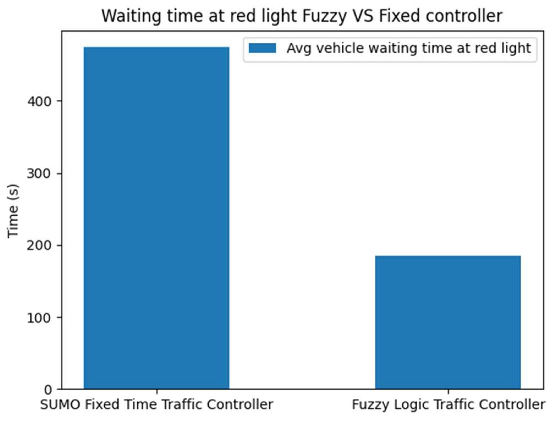
Figure 8.
Combined waiting Time Fuzzy vs Fixed.
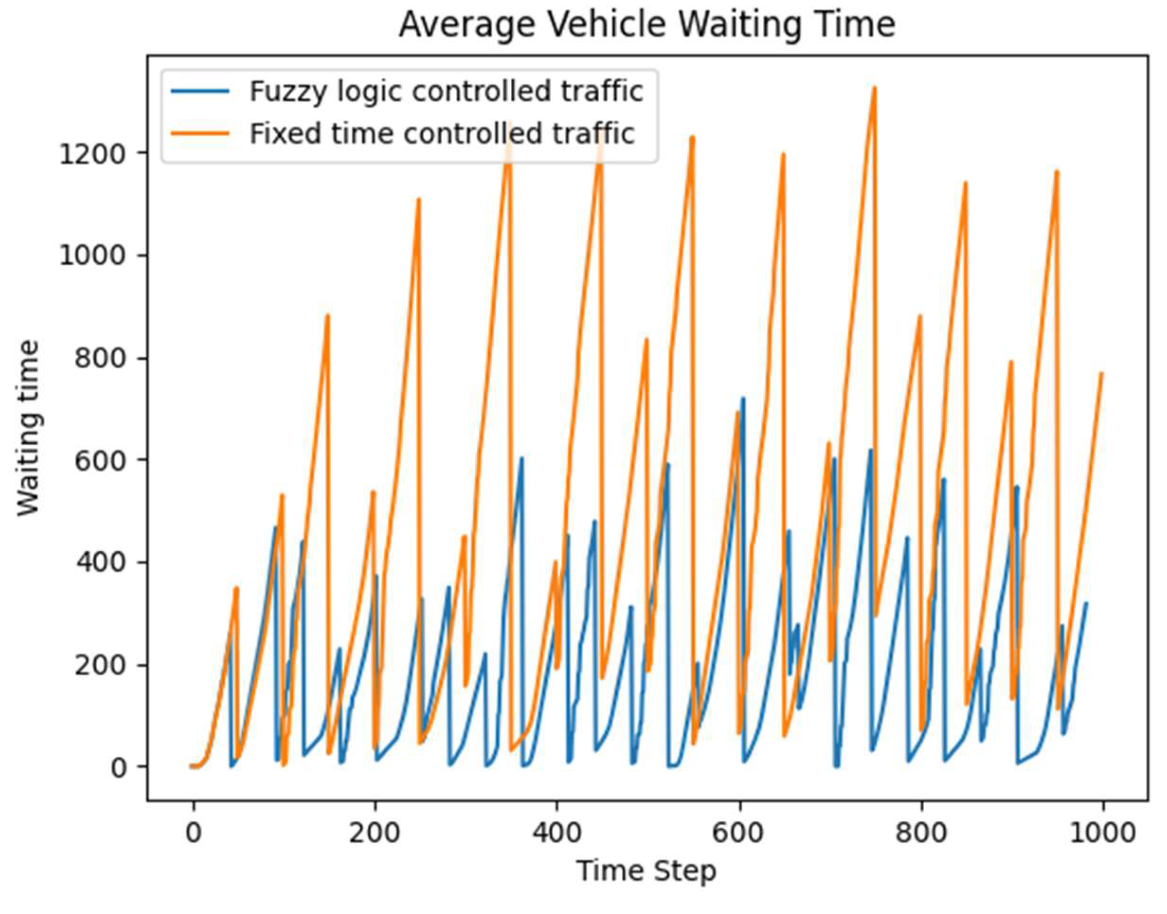

Table 1.
Impact of threshold on Traffic Light Controller Performance.
| Threshold Value (FIS threshold Unit) | Total Waiting Time (secs) | Number of Signal Changes | Average Vehicle Speed (km/h) |
| 0.30 | 72,257 | 48 | 16.65 |
| 0.35 | 72,252.077 | 48 | 16.65 |
| 0.40 | 71,470.049 | 46 | 16.72 |
| 0.45 | 84,246.454 | 33 | 18.30 |
| 0.50 | 246,974.142 | 19 | 28.99 |
| 0.60 | 206,403.332 | 0 | 28.88 |
Table 2.
Comparison of Average Vehicle Waiting Times Between Fixed-Time & Fuzzy controllers at Different Updated Intervals.
Table 2.
Comparison of Average Vehicle Waiting Times Between Fixed-Time & Fuzzy controllers at Different Updated Intervals.
| Condition | SUMO Fixed Time Traffic Controller Wait time (s) | Fuzzy Logic Traffic Controller Wait Time (s) |
| TL update 35s | 400 | 250 |
| TL update 40s | 400 | 250 |
| TL update 45s | 400 | 300 |
| TL update 50s | 400 | 370 |
| TL update 60s | 400 | 400 |
Disclaimer/Publisher’s Note: The statements, opinions and data contained in all publications are solely those of the individual author(s) and contributor(s) and not of MDPI and/or the editor(s). MDPI and/or the editor(s) disclaim responsibility for any injury to people or property resulting from any ideas, methods, instructions or products referred to in the content. |
© 2024 by the authors. Licensee MDPI, Basel, Switzerland. This article is an open access article distributed under the terms and conditions of the Creative Commons Attribution (CC BY) license (http://creativecommons.org/licenses/by/4.0/).
Copyright: This open access article is published under a Creative Commons CC BY 4.0 license, which permit the free download, distribution, and reuse, provided that the author and preprint are cited in any reuse.


