Submitted:
05 June 2024
Posted:
07 June 2024
You are already at the latest version
Abstract
This study introduces an innovative approach to designing membranes capable of separating CO2 from industrial gas streams at higher temperatures. The novel membrane design seeks to leverage the well-researched high-temperature CO2 adsorbent, hydrotalcite, by transforming it into a membrane. This is achieved by combining it with an amorphous organo-silica-based matrix, extending the polymer-based Mixed Matrix Membrane concept to inorganic compounds. Following the membrane material preparation and investigation of the individual membrane in Part 1 of this study, we examine its permeation and selectivity here. The pure 200 nm thick hydrotalcite membrane exhibits Knudsen behavior due to large intercrystalline pores. In contrast, the organo-silica membrane demonstrates a permselectivity of 13.5 and permeance for CO2 of 1.3 107 mol m2 s1 Pa1 at 25°C, at 150°C the good separation behavior is reduced. Combining both components results in a hybrid microstructure, featuring selective surface diffusion in the microporous regions and unselective Knudsen diffusion in the mesoporous regions. Further attempts to bridge both components to form a purely microporous microstructure are outlined.
Keywords:
inorganic membrane
; silica membrane
; CO2/N2 separation
; hydrotalcite membrane
; microporous mixed matrix membrane
1. Introduction
Providing captured CO2 from industrial exhaust streams is a basic premise for circular processing e.g. in methanisation or reverse water-gas-shift. A continuous and concentrated CO2 stream at temperatures exceeding 200°C is necessary for efficient process operation. However, no separation process currently operates continuously without experiencing a temperature drop.
State of the art separation processes for carbon capture, such as methanol scrubbing, operate at low temperatures whilst pressure-swing-adsorption (PSA) yields CO2 pseudo-continuously [1]. Current developments facilitate adsorption at higher temperatures by employing appropriate high-temperature adsorbents and implementing intelligent process interconnections. However, this approach requires relatively high operating costs and capital investment. Membrane processes might offer a solution by utilizing separation layers that incorporate adsorbents, allowing for the separation of CO2 at elevated temperatures [2]. These processes can provide continuous volume flows by spatially separating adsorption and desorption through diffusion across the membrane (see Figure 1). Therefore, membrane processes can be viewed as spatially separated PSA applications.
A vast amount of research is dedicated to the development of membranes with the potential to overcome the previously mentioned separation challenges. Gas separation membranes still do not manage to separate CO2 from N2 selectively while maintaining high flows at high temperatures. This work tries to offer a new route in developing high-temperature gas separation membranes by combining high-temperature adsorbents within well-known amorphous matrices.
Operational conditions at temperatures above 200°C exclude polymeric membranes for gas separation [3]. Therefore, the focus shifts to porous inorganic membranes, as they can withstand these conditions.
To design selective membranes, the mass transport mechanisms of the respective gas components in the membrane are the critical design criteria. The mass transport characteristics in porous materials are primarily influenced by the size of the pore diameter dp. In macro pores (dp > 50 nm), the primary mechanism is viscous flow, and the material of the membrane plays a negligible role in mass transport kinetics due to the pores being larger than the mean free pathways of gaseous compounds.
Smaller pores within the mesopore range (2 nm < dp < 50 nm) experience increased prominence of Knudsen diffusion. Mass transport kinetics in these pores are influenced by the molecular weight, with lighter molecules exhibiting faster movement.
In membranes containing micropores (dp < 2 nm), the impact of the internal surface becomes relevant, facilitating the adsorption/desorption behavior of gas components as an additional mass transport effect. In such cases, the membrane material becomes the dominant factor influencing mass transport kinetics, given the significance of mass transport over the surface [4,5].
Within the ultramicroporous range (dp << 1 nm), the selective exclusion of gaseous molecules begins, resulting in a decline in permeation or molecules larger than the pore opening, eventually approximating zero. Membranes featuring pores within the molecular sieving range can demonstrate significant selectivities. Nevertheless, such membranes often display very low fluxes for the permeating component, influenced by temperature-dependent activated permeation [6]. The same phenomena are observed for molten hydroxides and carbonate membranes operating at high temperatures [7] showing good permeances above 650°C - 850°C [8,9]. Therefore, membranes with pore sizes below 2 nm, made of a CO2 adsorption agent, are the most efficient solution for CO2 gas separation [4,5].
Several membrane materials based on various zeolites [10], metal-organic frameworks (MOFs) [11], carbon-based membranes [12], and sol-gel derived silica gels [13,14] have been extensively studied for selectivity of CO2 in microporous media. Silica membranes demonstrate good selectivity for CO2 and reasonable permeance.
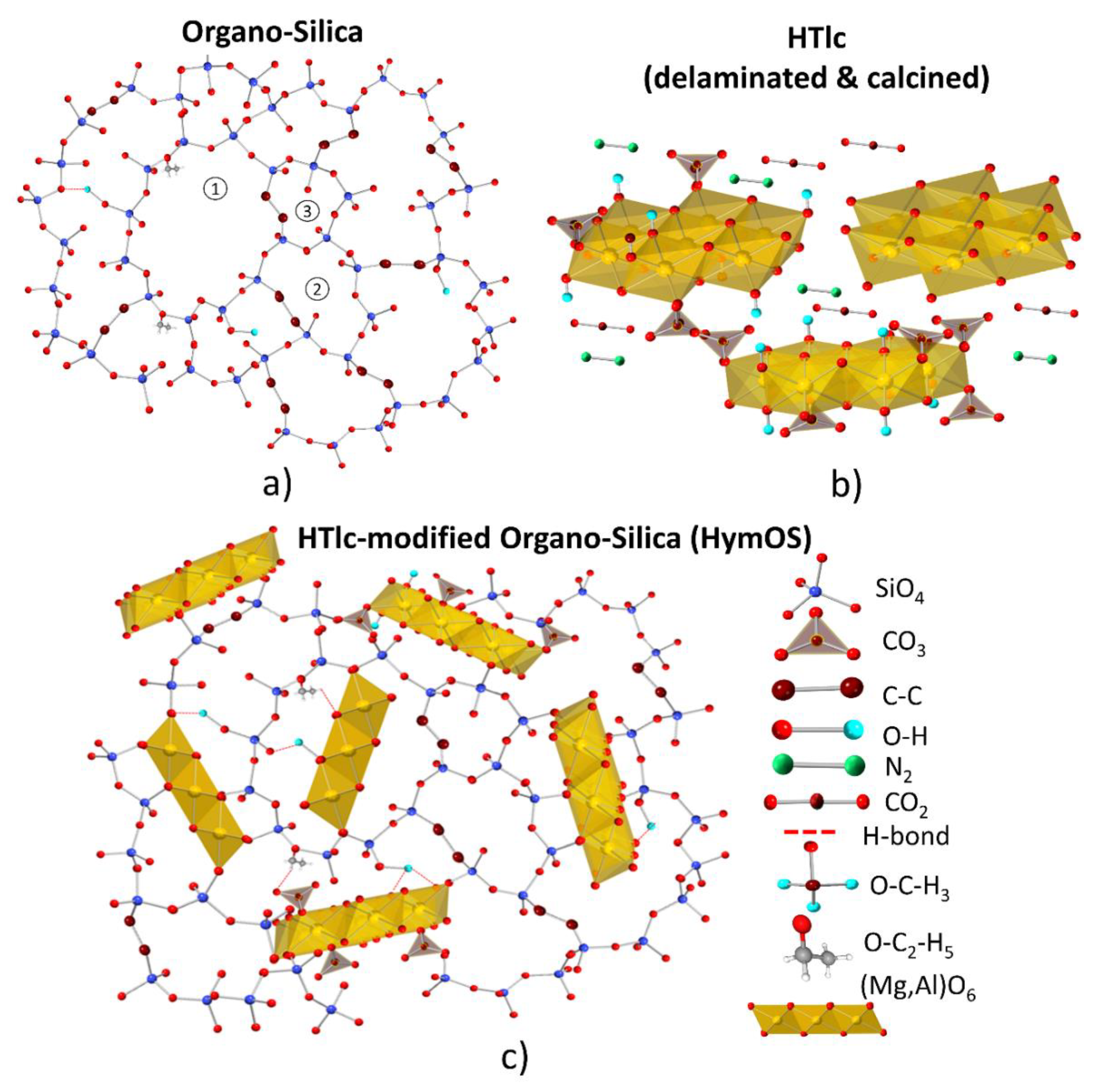
Figure 2a portrays the amorphous organo-silica structure, wherein mass transport occurs along the interior of the silica network through pores of different sizes (pores with different sizes marked by (1), (2), and (3). The selectivity of silica membranes is primarily based on their adsorptive affinity for CO2. However, the utilization of silica membranes is limited to lower temperature ranges (<200°C) due to a strong decrease in their adsorption capacity upon increasing temperatures [15,16] .
Therefore, for a membrane to effectively separate CO2 at high temperatures, the active membrane material must provide adsorption sites with a high exothermic heat of adsorption at operation temperature.
The field of high-temperature adsorbents has received a lot of attention, leading to the identification of a layered double hydroxides (LDH) as a suitable precursor for CO2 adsorption applications at elevated temperatures [17,18,19,20]. The used LDH can differ in the composition of cations (e.g Mg, Al, Fe, Co, Mo,…etc.), anions (e.g. sulfate, chlorides, nitrates), structural order (crystalline, partially disordered, amorphous) as well as in content and bonding of hydrogen (hydrous/anhydrous, partially dehydroxylated up to hydrogen-free, “mixed oxides”)[21]. While there is extensive research on the use of calcined hydrotalcite-like components (HTlcs) as an adsorbent, there have been relatively few investigations regarding its application as an active separation agent, particularly as the sole membrane material for gas separation. Membranes solely made of LDHs yielded low selectivity for CO2 as the fabricated membranes showed pore structures that favored Knudsen diffusion [22,23]. Figure 2b shows the delaminated calcined HTlc membrane microstructure schematically as a result of thermal treatment and delamination
The approach to overcome the selectivity problem is demonstrated by mixing a crystalline compound with high selective diffusion properties into an amorphous matrix as shown in Figure 2 c. This is state-of-the-art for polymeric matrixes [24]. There are several approaches for the use of LDH as a filler in polymeric matrices forming classic mixed matrix membranes (MMM). They all show good separation behavior but have limited temperature stability and low permeance [25]. Glassy inorganic MMMs however are not well investigated, yet. Embedding a sorption-enhancing agent into a silica membrane is studied by the group of Othman and Wiheeb with tetraethylorthosilicate as a precursor for silica, which is very sensitive to moisture for applications in flue gases with water content [26,27,28,29,30,31].
Figure 2.
Schematic visualization of the microstructures of (a) Organo-Silica, (b) the pure calcined hydrotalcite (c) and the Hydrotalcite modified Organo-Silica (HymOS) as the combination of both (c).
Figure 2.
Schematic visualization of the microstructures of (a) Organo-Silica, (b) the pure calcined hydrotalcite (c) and the Hydrotalcite modified Organo-Silica (HymOS) as the combination of both (c).
This work presents a possible way to combine the adsorptive effect of calcined HTlc with an amorphous silica matrix to enhance the separation performance at high temperatures. First, a description of the individual preparation methods for silica and hydrotalcite membranes as well as for the combination of the two materials is given. Second, the experimental setup for conducting mass transport experiments with the prepared membrane is illustrated. Finally, the preparation techniques and the corresponding mass transport performance are evaluated.
2. Materials and Methods
Membrane Fabrication
As a substrate for membrane deposition, a macroporous α-alumina disc with a thickness of 2.2 mm and a diameter of 39 mm with an approximate pore size of 80 nm of its top layer (Pervatech, the Netherlands) was used. On the top of the α-Al2O3 substrate, a supportive intermediate mesoporous γ-Al2O3 layer was deposited, produced by sol-gel synthesis, using a thermally treated boehmite (γ-AlO(OH)) sol after the method of Yoldas [32]. To obtain reproducible layer thickness, 3.5 g of Polyvinylalcohol (PVA) is dissolved in 100 ml water and mixed with the boehmite sol in a ratio of 2:3.
A detailed description of the mass transport-enhancing compound synthesis, hydrotalcite, and respective analysis of all steps are given in part 1 of this work.
The HTlc used in this work is synthesized by dissolving 6.1 g of magnesium chloride hexahydrate and 2.41 g of aluminum chloride hexahydrate, with a molar ratio of Mg/Al = 3, in 100 ml methanol. This mixture is heated to 65°C and stirred under reflux. The pH is set by a solution of 3.8 g of sodium hydroxide in 100 ml of methanol that is added dropwise to the metal salt solution [33,34]. For a small particle size distribution, the synthesis time is reduced from 3 days to 1 hour.
After cooling the reaction mixture to room temperature, it is centrifuged, and the remaining pellet is dispersed in water. This process is repeated until the pH becomes neutral. The remaining pellet is then dispersed in water and left overnight to delaminate. As a result, a clear and stable dispersion of delaminated hydrotalcite-like nanosheets is produced. This sol is used to fabricate the pure HTlc membrane. After coating and drying thermal treatment to activate the agent was carried out at 400°C for 3 hours in air [17].
The synthesis of the microporous organo-silica membrane (Org-Sil), for CO2 separation, was performed after the approach of van Gestel et al. and Castricum et al.[16,35]. It involves mixing 16.655 ml of the membrane-forming precursor, 1,2-bis(triethoxysilyl)-ethane (BTESE), with 28.14 ml of ethanol (both Thermo Scientific chemicals), 0.63 ml of nitric acid (65 wt%), and 4.57 ml of water. These amounts result in a water-to-hydrolysable ethoxy group ratio of one. The rapid mixing and reaction of the starting materials redundancies the use of ice bad as elsewhere described. The resulting mixture was heated to 60°C and refluxed for 90 minutes, followed by cooling to room temperature. The sol was stabilized for storage by the addition of 50 ml ethanol. The resulting mixture was stored in the refrigerator (stock sol). For the coating process in terms of the formation of defect-free films, the mixture was diluted in a ratio of 1 to 20 with ethanol. After coating and drying at room temperature for 1 hour, thermal treatment of the membrane was conducted under an N2 atmosphere at 300°C for 3 hours [35,36].
A detailed description of the process to transfer the water-based HTlc sol into a mixable solution with silica is given in part 1 of this study. The stable delaminated HTlc sol is first dried and then calcined at 400°C. Two grams of the resulting calcined and ground hydrotalcite are redispersed in ethanol with the assistance of an ultrasonic device.
To ensure the removal of undispersed particles, the dispersion was subjected to centrifugation for 20 min at 4000 rpm, resulting in a stable dispersion of calcined delaminated hydrotalcite-like nanosheets.
Various mixing ratios of both sols were explored, but only the lower and higher ends of the mixing range are presented here.
At the lower end of the mixing range, 100 ml of the same silica sol used for the pure organo-silica (Org-Sil) membrane was combined with 5 ml of ethanol-based hydrotalcite sol to form the HymOS1-sol. At the higher end of the mixing range, 100 ml of the hydrotalcite dispersion was mixed with 5 ml of the silica stock sol resulting in the HymOS2-sol. After 30 minutes of mixing, the mixtures were ready for coating onto the substrate to form the mixed matrix membranes. The resulting as-deposited film was then allowed to air dry for approximately 1 hour. Subsequently, thermal treatment was carried out at 300°C for 3 hours under a N2 atmosphere.
The coating process for all the aforementioned sols was performed uniformly. A 39 mm disc, used as the substrate, was attached to a vacuum suction cup located at the end of a rotating pendulum. A petri dish containing 50 ml of the respective sol was positioned at the lowest point of the pendulum. The coating process involved immersing the polished surface of the substrate into the sol with a controlled and defined velocity.
Once the pendulum reached a perpendicular position, its movement was halted for 15 seconds. After this pause, the substrate was rotated out of the sol with the same velocity as before. To prevent cracking caused by thermally induced tension, both the heating and cooling rates during thermal treatment were controlled to be 1 K/min. To ensure the production of crack-free membranes, all coating and thermal treatment processes were conducted twice. Afterward, the membranes were ready for structural and permeation analysis.
Structural Characterization
A high-resolution scanning electron microscope (SEM) was used for qualitative assessment of the prepared membrane layers. Images were captured using the Zeiss Supra 55 VP microscope with an acceleration voltage of 18 kV.
To prepare the membrane for SEM analysis, a crucial step involved freezing the glassy silica layer by placing the membrane disc in liquid N2. This step was essential for obtaining high-quality images, as attempts to analyze the membrane without this freezing step resulted in images with varying quality. After spending a few minutes in liquid N2, the membrane was cut into small 1 mm² pieces using a side cutter. In a further step, the pieces were then sputtered with gold to ensure electrical conductivity.
Additional analyses by X-ray diffraction, IR, and Raman spectroscopy and thermal analysis of the products after every step of preparation are extensively described in part 1 of this study.
Gas Permeation and Separation Experiments
A custom-made cell designed to hold 39 mm membrane discs, was used for single gas experiments. The top of the membrane was sealed via a 32 mm Viton O-ring to the cell resulting in an effective permeation area Am of 804 mm2. The thermal stability of the Viton limited the use of this setup to temperatures up to 200°C.
The gases used in this study were delivered from gas bottles with reducers, allowing measurements at pressures up to 6 bar. They were fed in the cell via an inlet on the top side. The setup also included a retentate outlet (top side), as well as a permeate outlet at the bottom side of the cell. A Bronkhorst El Press pressure controller valve was installed in the retentate line. Pressure measurements were performed in the feed pf and the permeate pp line.
The mass flow of the permeating stream was quantified by three Bronkhorst EL-Flow Prestige mass flow meters with different measurement ranges to reduce the measurement error (0-1g/h, 0-10g/h, 200g/h). A Membrane pump (KNF LABORPORT N938.50) installed in the permeate line allowed vacuums as low as 70 mbar. To measure the membrane performance at different temperatures, the module was placed in an oven. The temperature was controlled with a thermocouple installed in the proximity of the membrane.
The Permeance Qi is calculated from the measured membrane area, transmembrane pressure difference and mole flow according to equation (1)
The permselectivity Si/j as the ratio of the single gas permeances is calculated by equation (2)
A resistance-in-series model is utilized to determine the successive mass transport resistances in the composite membrane [22]. The resistance of each layer is inversely proportional to the intrinsic mass transport kinetics of the layer l, expressed by its permeability, Pi. Sequential measurements of each membrane layer provide the permeance (Eq. (1)), and using the corresponding membrane thickness, dl, obtained from SEM images, the permeability is calculated according to Equation (3).
3. Results
3.1. HTlc Membrane
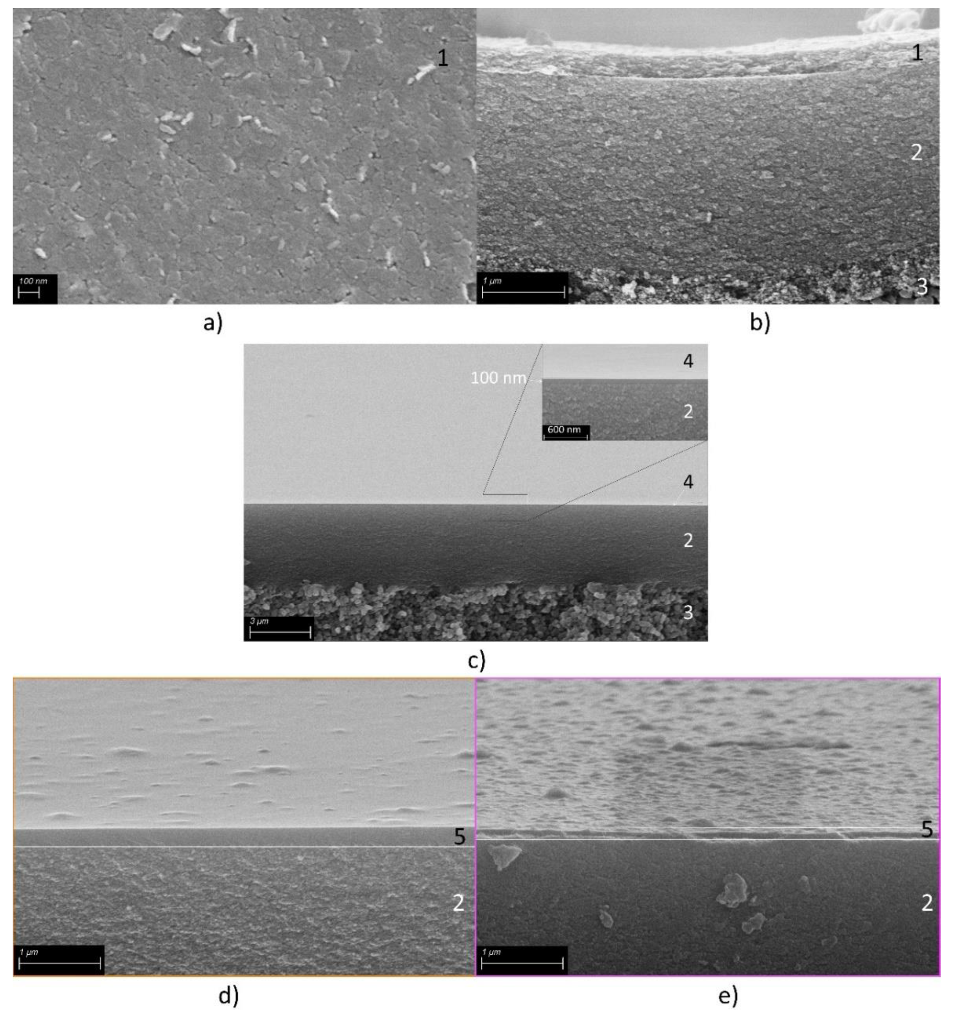
Figure 5 presents SEM images of a pure calcined delaminated hydrotalcite-like membrane, showing the surface (a) and the cross-section (b). In panel a, the characteristic platy hexagonal shape of the crystal is evident, and due to the membrane coating process, all crystals are preferentially oriented parallel to the substrate. Figure 5b shows a defect-free calcined HTlc layer with a thickness of 200 nm on top of a 2,2µm thick γ-Al2O3 layer.
For a better comparison and understanding of the influence of the support layers of the membrane, a consecutive investigation of the membrane layers was conducted. Figure 3 shows the permeance of the substrate and the substrate + γ-Al2O3 layer, respectively. A detailed listing of all permeance & permeabilities is shown in Table 1. The supporting layers show Knudsen behavior, the pure support shows slightly higher permeance than the combination of the support with the γ-Al2O3 layer. This is as expected since the γ-Al2O3 layer introduces an additional resistance.
The permeance in the HTlc membrane is lower for both components (2.5 10-7 mol m-2 s-1 Pa-1 for CO2 and 3.1 10-7 mol m-2 s-1 Pa-1 for N2) than in the supporting layers demonstrating a further resistance for the permeating gas molecules. Additionally, N2 is the primary permeating component, displaying a similar behavior to γ-Al2O3 and the substrate, albeit at a lower level. This suggests that the pure calcined HTlc layer possesses a structure with fewer or smaller pores than the other layers. The selectivity for CO2 at 20°C is 0.81, indicating that the diffusion through this layer is primarily governed by Knudsen diffusion. Based on the selectivity the size of the pores is in the same range as in the support. However, the lower flux is a consequence of the orientation of the crystals. They are arranged parallel to the substrate surface, thereby blocking a portion of the flow, as there is no direct path for diffusion through the crystal.
To our knowledge no pure hydrotalcite membrane with surface diffusion as the predominant mass transport mechanism has been reported yet. However, its theoretical feasibility is convincing. For a material to have surface diffusion that can impact the overall mass transport its heat of adsorption is crucial. Calcined hydrotalcite exhibits a heat of adsorption for CO2 in the range of 40-50 kJ mol-1 at temperatures between 573K and 623K [37,38]. This enables surface diffusion according to the correlation presented by Yang [38,39]. The resulting surface diffusion coefficient ranges in the way of 10-4 to 10-5 cm2s-1. This is in the same range as the diffusion of CO2 on silica at 300 K [40]. This shows that calcined HTlcs are a suitable material for enhancing mass transport at elevated temperatures.
However, the way the crystals are arranged always leads to inter-crystalline pores in the range where Knudsen diffusion is dominating. Therefore, it is not possible to take advantage of the CO2 affine surface. Several studies have observed the similar diffusion through pure hydrotalcite layers with permeabilities in the same range (see Table 1) but always with selectivities in the Knudsen range [22,23]. To shift the mass transport from diffusion through the free pore volume to surface diffusion, the free volume must be reduced. Approaches to achieve this comprise stacking the hydrotalcite layers up to 300 µm thick packages that show selectivity for CO2 but lead to very low permeances due to the enhanced layer thickness [22]. More promising is the effort to fill the free volume with a permeable material that allows for economically feasible flows. This leads to mixed matrix membranes that utilize polymers as the permeable matrix. Tsotsis et al. tried silicone as a matrix material with success, creating membranes with high selectivities but still on a low permeance level and with no application at higher temperatures [23].
The approach in this work focuses on creating a microstructure where an organo-silica inorganic polymer fills up the free space between the HTlc phase. It tries to transfer the idea of organic matrices with an inorganic filler to a membrane where the matrix is made of an inorganic material, too.
3.2. Pure Organo-Silica Membrane (Org-Sil)
To understand the inorganic matrix material, its permeating properties as a single layer are investigated. Figure 5c displays SEM images of an organo-silica membrane in a cross-section with the surface visible in the upper part. Three distinct layers are visible. In the insert, the organo-silica top layer 4 is shown, with a thickness of about 100 nm and a defect-free smooth surface.
Single gas permeation experiments were conducted with CO2 and N2 to determine the permeation kinetics (see Figure 3 a). The organo-silica layer deposited on the top of the γ-Al2O3 layer shows different permeation behavior compared to the other membranes. While both gases traverse micropores, surface diffusion emerges as the predominant mass transport mechanism. For N2, which can solely diffuse through the free pore volume, the permeance decreases to approximately~0.1 10-7 mol m-2 s-1 Pa-1 at room temperature. CO2 having an additional diffusion path along the inner pore surface, undergoes a smaller decrease, resulting in a permeance of around~1.3 10-7 mol m-2 s-1 Pa-1. Consequently, the permselectivity reaches 13.
Figure 4.
Single-gas permeation of CO2 and N2 through an Org-Sil membrane (red) at different temperatures, in reference to the permeances shown in Figure 2 at 25°C. The transmembrane pressure is kept constant at 3.2 bar. Permeances for CO2 and N2 both in scientific and technical units.
Figure 4.
Single-gas permeation of CO2 and N2 through an Org-Sil membrane (red) at different temperatures, in reference to the permeances shown in Figure 2 at 25°C. The transmembrane pressure is kept constant at 3.2 bar. Permeances for CO2 and N2 both in scientific and technical units.
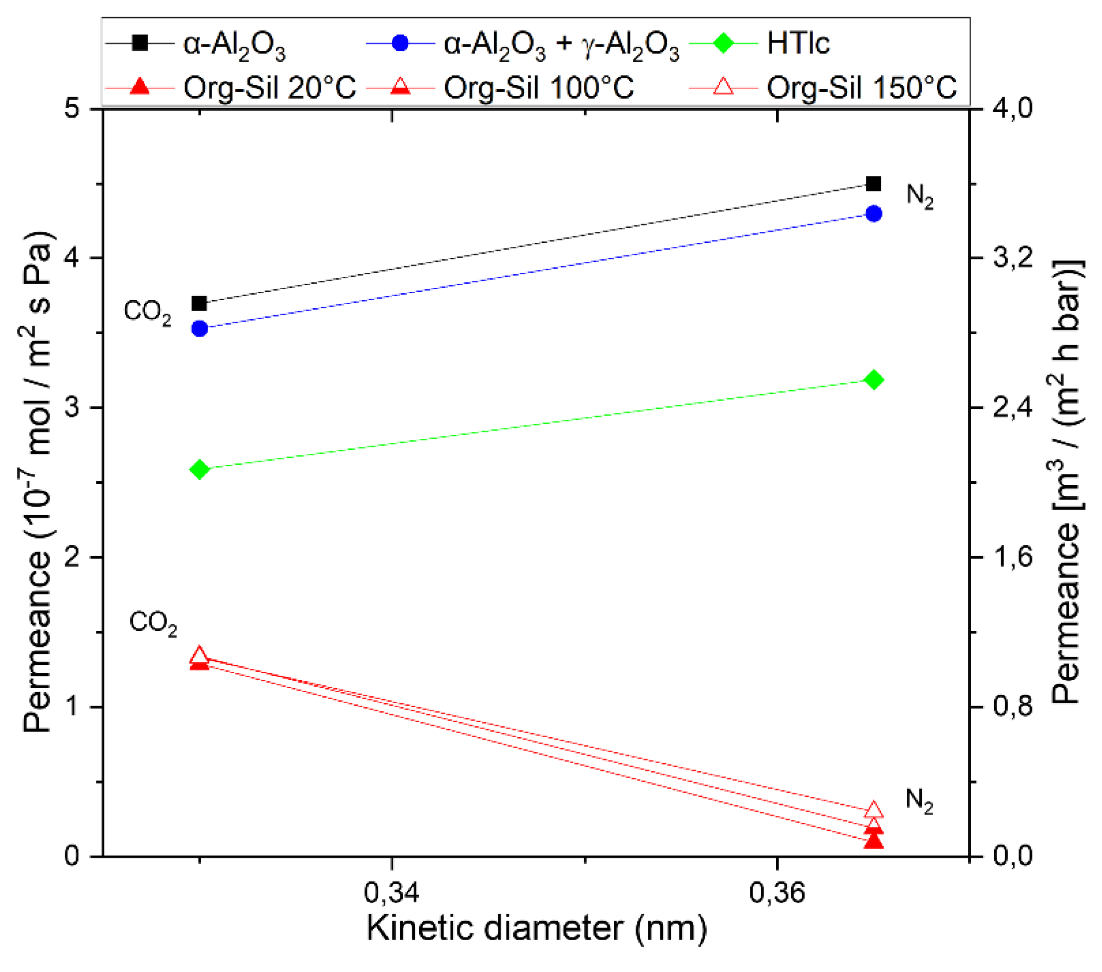
As temperature rises during organo-silica measurements, two distinct behaviors become apparent. Firstly, the permeance for N2 increases, attributed to activated permeation. A comprehensive description of activated permeation can be found in the study conducted by Lange et al. [41]. Secondly, the permeance for CO2 appears to remain unaffected. As temperature increases, activated permeation rises, while surface diffusion, which relies on active adsorption sites, decreases. [16]. These two mass transport mechanisms seem to counterbalance each other in the case of CO2, resulting in a relatively consistent permeance as temperature rises. However, because of the increasing N2 permeance, the selectivity diminishes to 4.3 at 150°C. For a better comparison of the intrinsic mass transport properties, all permeabilities are calculated and listed in Table 1.
While an efficient separation of N2 and CO2 is achievable at low temperatures, a decrease in separation efficiency at elevated temperatures is observed. This could be explained by the fact that whereas the CO2 permeance remains relatively constant at higher temperatures, the N2 permeance increases. The combination of organo-silica and HTlcs is expected to overcome the respective limitations in a novel MMM.
3.3. HTlc Modified Organo-Silica Membrane (HymOS)
Figure 5 displays two SEM images of the modified membrane with different HTlc concentrations: lower concentration (5d), and higher concentration (5e). The preparation of mixed membranes proved to be challenging in terms of HTlc/sol ratio. Too little hydrotalcite in the silica sol would not notably alter the mass transport behavior, while an excess would enlarge the pores creating voids and thus enhancing Knudsen diffusion as seen in Figure 2c [28,42].
Figure 5.
SEM Secondary electron images of a) the surface of calcined HTlc membrane (1), b) a cross-section of the composite membrane with 200 nm calcined HTlc on top of the mesoporous γ-Al2O3 mesolayer (2) and the pervatech macroporous support (3). Panel c) shows the microporous organo-silica top layer (4) on top of the γ-Al2O3 layer (2) and the α-Al2O3 support (3). The insert shows the same membrane at a higher magnification for better visualization of the organo-silica layer thickness. Panel (d) shows the HymOS1 membrane (5) with a low hydrotalcite concentration, and panel (e) the HymOS2 membrane with a higher concentration.
Both SEM images exhibit continuous and defect-free membranes with clearly seen differences in the hydrotalcite content. To assess the functionality of the prepared membranes, single-gas experiments were conducted. Figure 6. illustrates the permeance of HymOS1 and HymOS2. All permeances and permeabilities are listed in Table 1. A resistance-in-series model is employed to calculate the consecutive mass transport resistances [43].
Both membranes exhibit higher permeance values for both components compared to the pure organo-silica membrane. This outcome aligns with expectations, as the presence of HTlcs disrupts the silica microstructure, increasing porosity and pore size. For HyMOS1, with lower hydrotalcite content, the permeance increased from around 1.4 10-7 mol m-2 s-1 Pa-1 to 1.85 10-7 mol m-2 s-1 Pa-1 for CO2 and from 0.09 10-7 mol m-2 s-1 Pa-1 to 0.6 10-7 mol m-2 s-1 Pa-1 for N2. Consequently, the selectivity dropped from 13 to 3. The second membrane (HyMOS2), with higher hydrotalcite content, demonstrates similarly elevated permeance for both components, albeit at a higher level. With more hydrotalcite crystals further disrupting the microstructure, the ratio favoring Knudsen diffusion is intensified, leading to a further reduced selectivity of 1.6.
4. Discussion
Research efforts have yielded various materials that potentially facilitate the selective separation of N2 from CO2. This study focused on utilizing a hydrotalcite-derived component in a way that has not been investigated, yet. Numerous studies prepared membranes by use of some LDH-derived components [44]. Most are designed to facilitate selectivity by molecular sieving through the interlayer gallery. Some have prepared LDHs with CO2 transport channels that have some sort of carrier mechanic that is highly selective for CO2 [45]. Former membranes lack the applicability for flue gas cleaning as the permeances are low and expected to decrease further if mixed gas permeances were investigated. The transport channel membranes however show enormous permeances while having high selectivities. To our knowledge, the transport mechanism is highly pressure-dependent and reduces at technical operation points.
Therefore, this study tried to introduce a membrane with a third option of facilitating high flux and high selectivity at elevated temperatures by utilizing calcined hydrotalcite, which has proven its application in high-temperature CO2 adsorbent processes. Creating selective CO2 diffusion paths by providing high-temperature adsorption sites within a matrix is a membrane design concept with little research, yet.
For the insertion of an active separation agent into a permeable matrix to form a functioning membrane an imagined resistance interconnection needs to be considered [46]. As proposed by Zimmermann et al. MMMs with polymeric matrices can be viewed as parallel resistance of the respective permeating components [47]. This approach is transferred to inorganic-inorganic hybrid microstructures. Equations (2) show the effective permeance Q for CO2 and equation (3) for N2 through an imagined MMM with the volume fraction Φ of the calcined HTlc. The permeance through the silica matrix is described by (), exhibiting a decreasing portion of the overall permeance with increasing volume fraction of the HTlc phase.
For the mixture to be a selective membrane the mass transport of CO2 along the surface of the HTlc () needs to reach higher values than for N2 () at operating temperatures. Increasing the volume fraction of HTlcs improves the overall surface for CO2 diffusion. However, at the same time the filler material causes the creation of voids that favor Knudsen diffusion () and thus rendering the membrane less selective. Therefore, the membrane design needs to focus on finding the right amount of surface diffusion agent incorporated in the matrix to increase the selectivity. Figure 7 displays equation (2) & (3) schematically to show the proposed design criteria.
For low contents of HTlc the CO2 permeance increases faster than the Knudsen diffusion through the added free volume. In small pores the influence of the added surface favors surface diffusion. This trend is reversed as the pores get larger as the volume of the pores grows faster than the surface thus favoring Knudsen diffusion with higher permeances, leading to a decrease in the overall selectivity.
The prepared membranes in this work are located on the right side of Figure 7. Both membranes showed lower selectivities than the pure matrix (Φ = 0) and both have higher permeances. Further investigations with lower adsorption agent content or smaller particles that create less voluminous voids can shift the selectivity to its optimum. Furthermore, for the design of a functioning membrane, the bridging between matrix and HTlcs needs to be ensured. Part one of this study showed evidence for those bridges to form, however this process seems to be a challenge deserving optimization. This could be achieved with further manipulation of the boundary surfaces for faster polymerization via bridging oxygens between octahedral layers of the HTlc and silica. Variation of the acidity during the formation of the gels could also provide optimization of their pore size. In addition, the allocation of third-party bridging agents to help close of the voids seems a possible approach [42].
5. Conclusion
This work offers a new design approach to fabricating membranes for high-temperature gas separation. LDH of hydrotalcite type was synthesized, delaminated, and made into a 200 nm thick membrane, which provides highly CO2 affinitive adsorption sites after calcination. As expected the resulting pore size distribution favores unselective Knudsen diffusion. The microporous membrane, made of amorphous organo-silica showes selective permeation behavior up to 150°C. Combining both materials into a novel Mixed Matrix Membrane comprised of two inorganic materials proves to be possible. Although the functionality of the mixed organosilica-HTlc membrane seems still to be temperature-limited for gas separation, these materials provide a large field for optimization. A combination of unselective Knudsen diffusion and selective surface diffusion explained the observed permeation behavior of the MMM. Incorporating the crystalline adsorption agent into the microporous structure is assumed to create voids at the interfaces that favor Knudsen diffusion. As a main objective for further research, the optimization of both: pore size distribution of the gel matrix as well as the improvement of the connectivity between the gel bridging sites and octahedral layers are identified.
This work establishes the foundation for membranes of this kind and fosters research for finding ways to overcome the bridging problems between both components.
Author Contributions
Conceptualization, L.B.; methodology, L.B.; validation, L.B., T.K.; formal analysis, L.B.; investigation, L.B.; data curation, L.B.; writing—original draft preparation, L.B.; writing—review and editing T.K. K.G. P.S. D.S.; visualization, T.K and L.B.; supervision, K.G, P.S and D.S.; funding acquisition, D.S. All authors have read and agreed to the published version of the manuscript.”
Funding
Program-oriented funding for this research was provided through the German Helmholtz association in the frame of the “Materials and Technologies for the Energy Transition” program.
Institutional Review Board Statement
Not applicable
Data Availability Statement
The data that support the findings of this study are available from the corresponding author, upon request.
Conflicts of Interest
The authors declare no conflict of interest
References
- Sircar, S. Pressure Swing Adsorption Technology. In Adsorption: Science and Technology; Rodrigues, A.E., LeVan, M.D., Tondeur, D., Eds.; Springer-Verlag: Dordrecht, 1989; pp 285–321.
- Kenarsari, S.D.; Yang, D.; Jiang, G.; Zhang, S.; Wang, J.; Russell, A.G.; Wei, Q.; Fan, M. Review of recent advances in carbon dioxide separation and capture. RSC Adv. 2013, 3, 22739. [CrossRef]
- Rezakazemi, M.; Sadrzadeh, M.; Matsuura, T. Thermally stable polymers for advanced high-performance gas separation membranes. Prog. Energy. Combust. Sci. 2018, 66, 1–41. [CrossRef]
- Baker, R.W. Membrane Transport Theory. In Membrane Technology and Applications; Baker, R.W., Ed.; John Wiley & Sons, Ltd: Chichester, UK, 2004; pp 15–87.
- Burggraaf, A.J. Transport and separation properties of membranes with gases and vapours. In Fundamentals of inorganic membrane science and technology; Burggraaf, A.J., Cot, L., Eds.; Elsevier: Amsterdam, 1996; pp 331–434.
- Robeson, L.M. Correlation of separation factor versus permeability for polymeric membranes. J. Membr. Sci. 1991, 62, 165–185. [CrossRef]
- Cerón, M.R.; Lai, L.S.; Amiri, A.; Monte, M.; Katta, S.; Kelly, J.C.; Worsley, M.A.; Merrill, M.D.; Kim, S.; Campbell, P.G. Surpassing the conventional limitations of CO2 separation membranes with hydroxide/ceramic dual-phase membranes. J. Membr. Sci. 2018, 567, 191–198. [CrossRef]
- Lu, B.; Lin, Y.S. Synthesis and characterization of thin ceramic-carbonate dual-phase membranes for carbon dioxide separation. J. Membr. Sci. 2013, 444, 402–411. [CrossRef]
- Anderson, M.; Lin, Y.S. Carbonate–ceramic dual-phase membrane for carbon dioxide separation. J. Membr. Sci. 2010, 357, 122–129. [CrossRef]
- Bernal, M.P.; Coronas, J.; Menéndez, M.; Santamaría, J. Separation of CO 2 /N 2 mixtures using MFI-type zeolite membranes. AIChE J. 2004, 50, 127–135. [CrossRef]
- Liu, Y.; Wang, N.; Diestel, L.; Steinbach, F.; Caro, J. MOF membrane synthesis in the confined space of a vertically aligned LDH network. Chem. Commun. (Camb ) 2014, 50, 4225–4227. [CrossRef]
- Richter, H.; Voss, H.; Kaltenborn, N.; Kämnitz, S.; Wollbrink, A.; Feldhoff, A.; Caro, J.; Roitsch, S.; Voigt, I. High-Flux Carbon Molecular Sieve Membranes for Gas Separation. Angew. Chem. Int. Ed Engl. 2017, 56, 7760–7763. [CrossRef]
- Vos, R.M. de; Verweij, H. High-selectivity, high-flux silica membranes for gas separation. Science 1998, 279, 1710–1711. [CrossRef]
- Elshof, J.E. ten. Hybrid Materials for Molecular Sieves. In Handbook of Sol-Gel Science and Technology; Klein, L., Aparicio, M., Jitianu, A., Eds.; Springer International Publishing: Cham, 2018; pp 1–27.
- Kanezashi, M.; Matsugasako, R.; Tawarayama, H.; Nagasawa, H.; Tsuru, T. Pore size tuning of sol-gel-derived triethoxysilane (TRIES) membranes for gas separation. J. Membr. Sci. 2017, 524, 64–72. [CrossRef]
- van Gestel, T.; Velterop, F.; Meulenberg, W.A. Zirconia-supported hybrid organosilica microporous membranes for CO2 separation and pervaporation. Sep. Purif. Technol. 2021, 259, 118114. [CrossRef]
- Ram Reddy, M.K.; Xu, Z.P.; Lu, G.Q.; Diniz da Costa, J.C. Layered Double Hydroxides for CO 2 Capture: Structure Evolution and Regeneration. Ind. Eng. Chem. Res. 2006, 45, 7504–7509. [CrossRef]
- León, M.; Díaz, E.; Bennici, S.; Vega, A.; Ordóñez, S.; Auroux, A. Adsorption of CO 2 on Hydrotalcite-Derived Mixed Oxides: Sorption Mechanisms and Consequences for Adsorption Irreversibility. Ind. Eng. Chem. Res. 2010, 49, 3663–3671. [CrossRef]
- Wang, Q.; Tay, H.H.; Ng, D.J.W.; Chen, L.; Liu, Y.; Chang, J.; Zhong, Z.; Luo, J.; Borgna, A. The effect of trivalent cations on the performance of Mg-M-CO(3) layered double hydroxides for high-temperature CO(2) capture. ChemSusChem 2010, 3, 965–973. [CrossRef]
- Bublinski, M. CO2-Abtrennung aus Synthesegasen mit Hydrotalciten unter Hochtemperatur-Hochdruckbedingungen. Dissertation; Universität Stuttgart, Stuttgart, 2016.
- Zhang, J.; Xu, Y.F.; Qian, G.; Xu, Z.P.; Chen, C.; Liu, Q. Reinvestigation of Dehydration and Dehydroxylation of Hydrotalcite-like Compounds through Combined TG-DTA-MS Analyses. J. Phys. Chem. C 2010, 114, 10768–10774. [CrossRef]
- Kim, T.W.; Sahimi, M.; Tsotsis, T.T. The Preparation and Characterization of Hydrotalcite Thin Films. Ind. Eng. Chem. Res. 2009, 48, 5794–5801. [CrossRef]
- Wook Kim, T.; Sahimi, M.; Tsotsis, T.T. The preparation and characterization of hydrotalcite micromembranes. Chem. Eng. Sci. 2009, 64, 1585–1590. [CrossRef]
- Vinoba, M.; Bhagiyalakshmi, M.; Alqaheem, Y.; Alomair, A.A.; Pérez, A.; Rana, M.S. Recent progress of fillers in mixed matrix membranes for CO 2 separation: A review. Sep. Purif. Technol. 2017, 188, 431–450. [CrossRef]
- Fajrina, N.; Yusof, N.; Ismail, A.F.; Jaafar, J.; Aziz, F.; Salleh, W.; Nordin, N. MgAl-CO3 layered double hydroxide as potential filler in substrate layer of composite membrane for enhanced carbon dioxide separation. J. Environ. Chem. Eng 2021, 9, 106164. [CrossRef]
- Wiheeb, A.D.; Ahmad, M.A.; Murat, M.N.; Kim, J.; Othman, M. Identification of Molecular Transport Mechanisms in Micro-Porous Hydrotalcite–Silica Membrane. Transp Porous Med 2014, 104, 133–144. [CrossRef]
- Wiheeb, A.D.; Ahmad, M.A.; Murat, M.N.; Kim, J.; Othman, M. The declining affinity of microporous hydrotalcite-silica membrane for carbon dioxide. J Por Media 2014, 17, 159–167. [CrossRef]
- Wiheeb, A.D.; Ahmad, M.A.; Murat, M.N.; Kim, J.; Othman, M. The Effect of Hydrotalcite Content in Microporous Composite Membrane on Gas Permeability and Permselectivity. Sep. Sci. Technol. 2014, 49, 1309–1316. [CrossRef]
- Wiheeb, A.D.; Kim, J.; Othman, M. Highly Perm-Selective Micro-Porous Hydrotalcite-Silica Membrane for Improved Carbon Dioxide-Methane Separation. Sep. Sci. Technol. 2015, 50, 1701–1708. [CrossRef]
- Wiheeb, A.D.; Mohammed, T.E.; Abdel-Rahman, Z.A.; Othman, M. Flow dynamics of gases inside hydrotalcite-silica micropores. Microporous Microporous Mater. 2017, 246, 37–42. [CrossRef]
- Wiheeb, A.D.; Ahmad, M.A.; Murat, M.N.; Kim, J.; Othman, M. Predominant Gas Transport in Microporous Hydrotalcite–Silica Membrane. Transp Porous Med 2014, 102, 59–70. [CrossRef]
- Yoldas, B.E. Alumina Sol Preparation from Alkoxides. Amer. Ceram. Soc. Bull. 1975, 289–290.
- Gardner, E.; Huntoon, K.M.; Pinnavaia, T.J. Direct Synthesis of Alkoxide-Intercalated Derivatives of Hydrocalcite-like Layered Double Hydroxides: Precursors for the Formation of Colloidal Layered Double Hydroxide Suspensions and Transparent Thin Films. Adv. Mater. 2001, 13, 1263. [CrossRef]
- Gursky, J.A.; Blough, S.D.; Luna, C.; Gomez, C.; Luevano, A.N.; Gardner, E.A. Particle-particle interactions between layered double hydroxide nanoparticles. J. Am. Chem. Soc. 2006, 128, 8376–8377. [CrossRef]
- Castricum, H.L.; Sah, A.; Kreiter, R.; Blank, D.H.A.; Vente, J.F.; Elshof, J.E. ten. Hydrothermally stable molecular separation membranes from organically linked silica. J. Mater. Chem. 2008, 18, 2150. [CrossRef]
- Kanezashi, M.; Yada, K.; Yoshioka, T.; Tsuru, T. Organic–inorganic hybrid silica membranes with controlled silica network size: Preparation and gas permeation characteristics. J. Membr. Sci. 2010, 348, 310–318. [CrossRef]
- Iruretagoyena Ferrer, D. Supported Layered Double Hydroxides as CO2 Adsorbents for Sorption-enhanced H2 Production; Springer International Publishing: Cham, 2016.
- Radha, S.; Navrotsky, A. Energetics of CO 2 Adsorption on Mg–Al Layered Double Hydroxides and Related Mixed Metal Oxides. J. Phys. Chem. C 2014, 118, 29836–29844. [CrossRef]
- R.T. Yang. Rate Processes in Adsorbers. In Gas separation by adsorption processes, 1.th ed.; Yang, R.T., Ed.; Butterworths: London, 1987; pp 108–124.
- Alsyouri, H.M.; Lin, J.Y.S. Gas diffusion and microstructural properties of ordered mesoporous silica fibers. J. Phys. Chem. B 2005, 109, 13623–13629. [CrossRef]
- Lange, R. de; Keizer, K.; Burggraaf, A.J. Analysis and theory of gas transport in microporous sol-gel derived ceramic membranes. J. Membr. Sci. 1995, 104, 81–100. [CrossRef]
- Goh, P.S.; Ismail, A.F.; Sanip, S.M.; Ng, B.C.; Aziz, M. Recent advances of inorganic fillers in mixed matrix membrane for gas separation. Sep. Purif. Technol. 2011, 81, 243–264. [CrossRef]
- Kim, T.W.; Sahimi, M.; Tsotsis, T.T. Preparation of Hydrotalcite Thin Films Using an Electrophoretic Technique. Ind. Eng. Chem. Res. 2008, 47, 9127–9132. [CrossRef]
- Lu, P.; Liu, Y.; Zhou, T.; Wang, Q.; Li, Y. Recent advances in layered double hydroxides (LDHs) as two-dimensional membrane materials for gas and liquid separations. J. Membr. Sci. 2018, 567, 89–103. [CrossRef]
- Xu, X.; Wang, J.; Zhou, A.; Dong, S.; Shi, K.; Li, B.; Han, J.; O'Hare, D. High-efficiency CO2 separation using hybrid LDH-polymer membranes. Nat. Commun. 2021, 12, 3069. [CrossRef]
- Monsalve-Bravo, G.; Bhatia, S. Modeling Permeation through Mixed-Matrix Membranes: A Review. Processes 2018, 6, 172. [CrossRef]
- Zimmerman, C.M.; Singh, A.; Koros, W.J. Tailoring mixed matrix composite membranes for gas separations. J. Membr. Sci. 1997, 137, 145–154. [CrossRef]
Figure 1.
Conceptual comparison of PSA and membrane processes for CO2/N2 separation. Panels a) show the CO2 mole fraction XCO2 in the gas phase as a function of the position z, a-I) in the adsorption column, and a-II) in the membrane, at a point in time t. Panels b), show the CO2 mole fraction in the gas phase as a function of the time, b-I) at the column head for the PSA, and b-II) at the permeate side for the membrane. In the process I (PSA) adsorption and desorption take place at the same location a-I), but at different times b-I). In process II (Membrane) adsorption and desorption are spatially separated a-II), but occur simultaneously b-II).
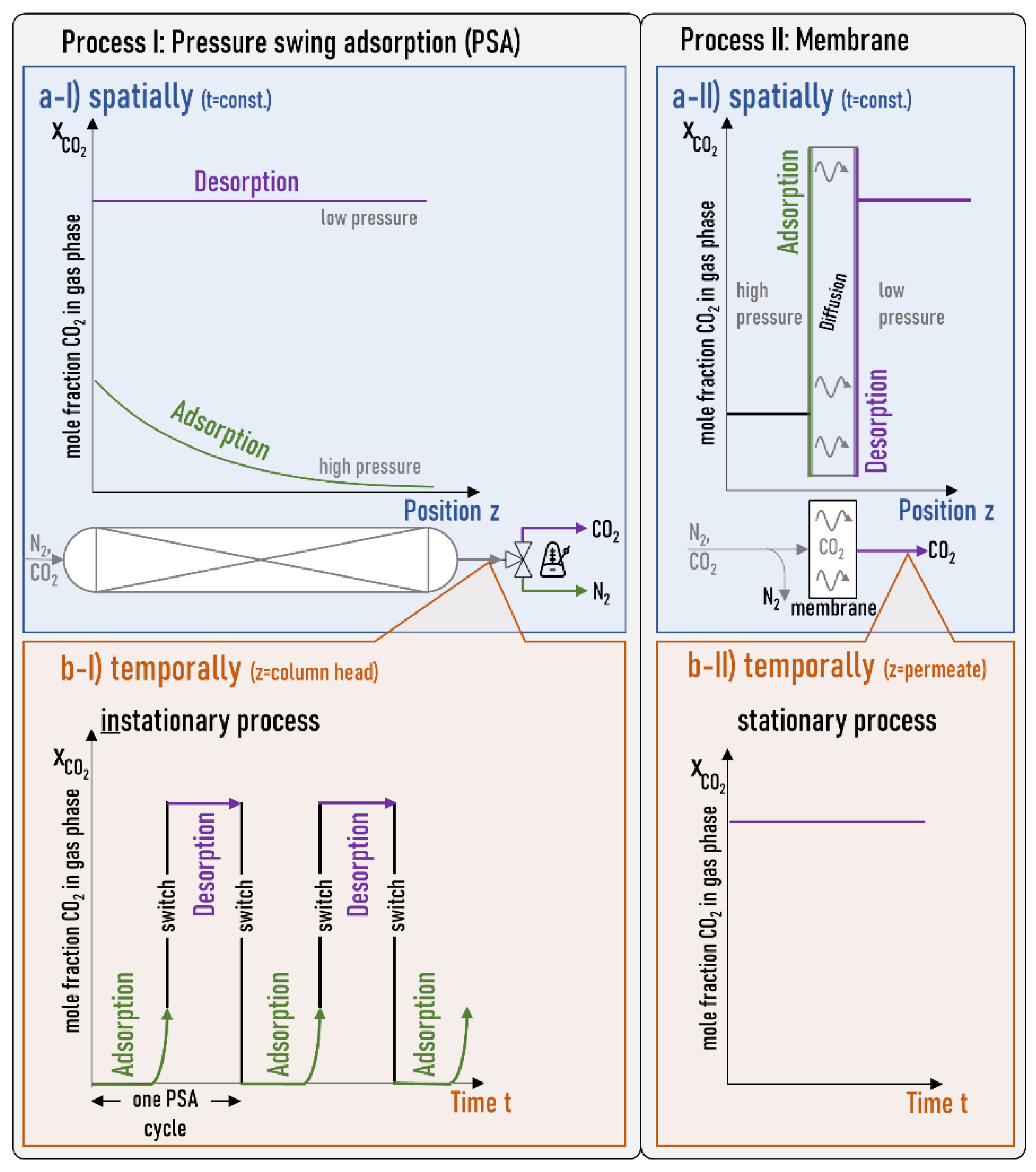
Figure 3.
Single-gas permeation through the α-Al2O3 support (squares), the support + γ-Al2O3 (circle), and the pure hydrotalcite membrane on top of both (diamond) at 25°C, 3.2 bar. Permeances for CO2 and N2 both in scientific and technical units.
Figure 3.
Single-gas permeation through the α-Al2O3 support (squares), the support + γ-Al2O3 (circle), and the pure hydrotalcite membrane on top of both (diamond) at 25°C, 3.2 bar. Permeances for CO2 and N2 both in scientific and technical units.
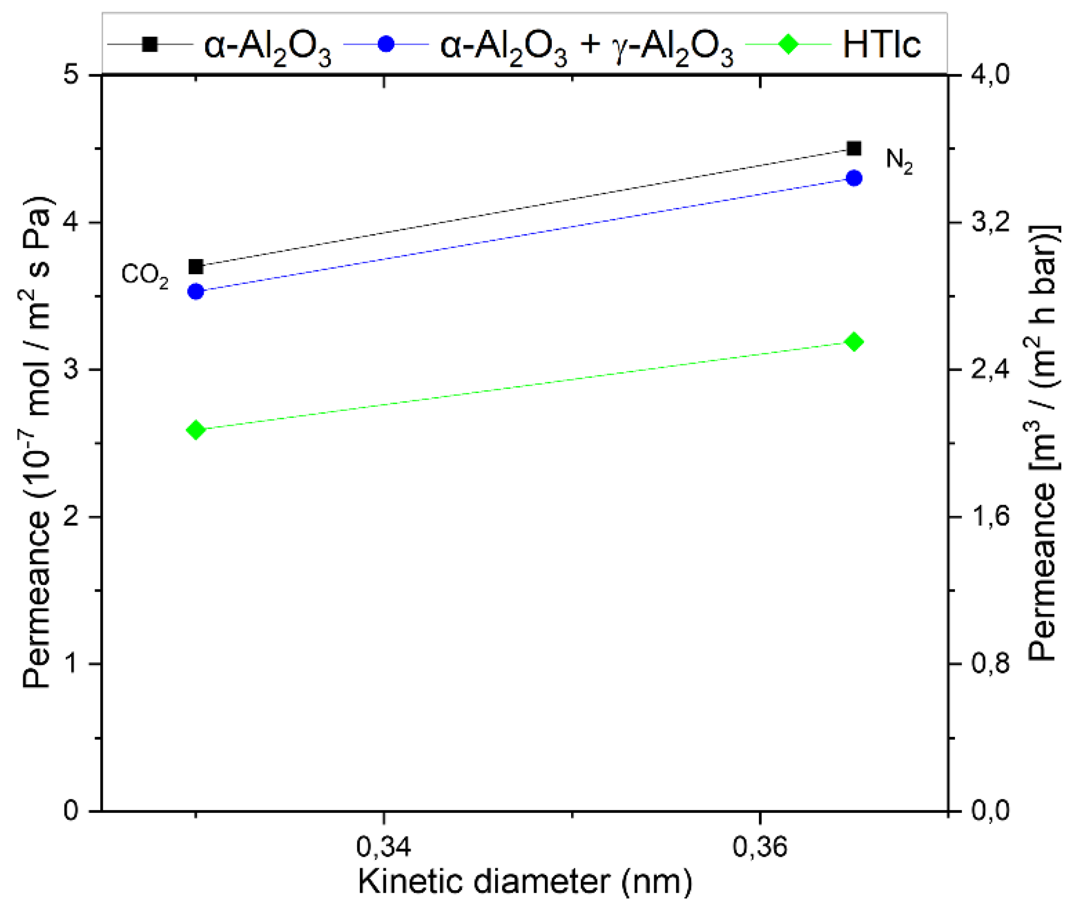
Figure 6.
Single-gas permeation at 20°C (other temperatures are indicated) through two modified membranes (HymOS1 orange star & HymOS2 pink square) in relation to the permeances of the single component membranes described before. The transmembrane pressure is kept constant at 3.2 bar. Permeances for CO2 and N2 both in scientific and technical units.
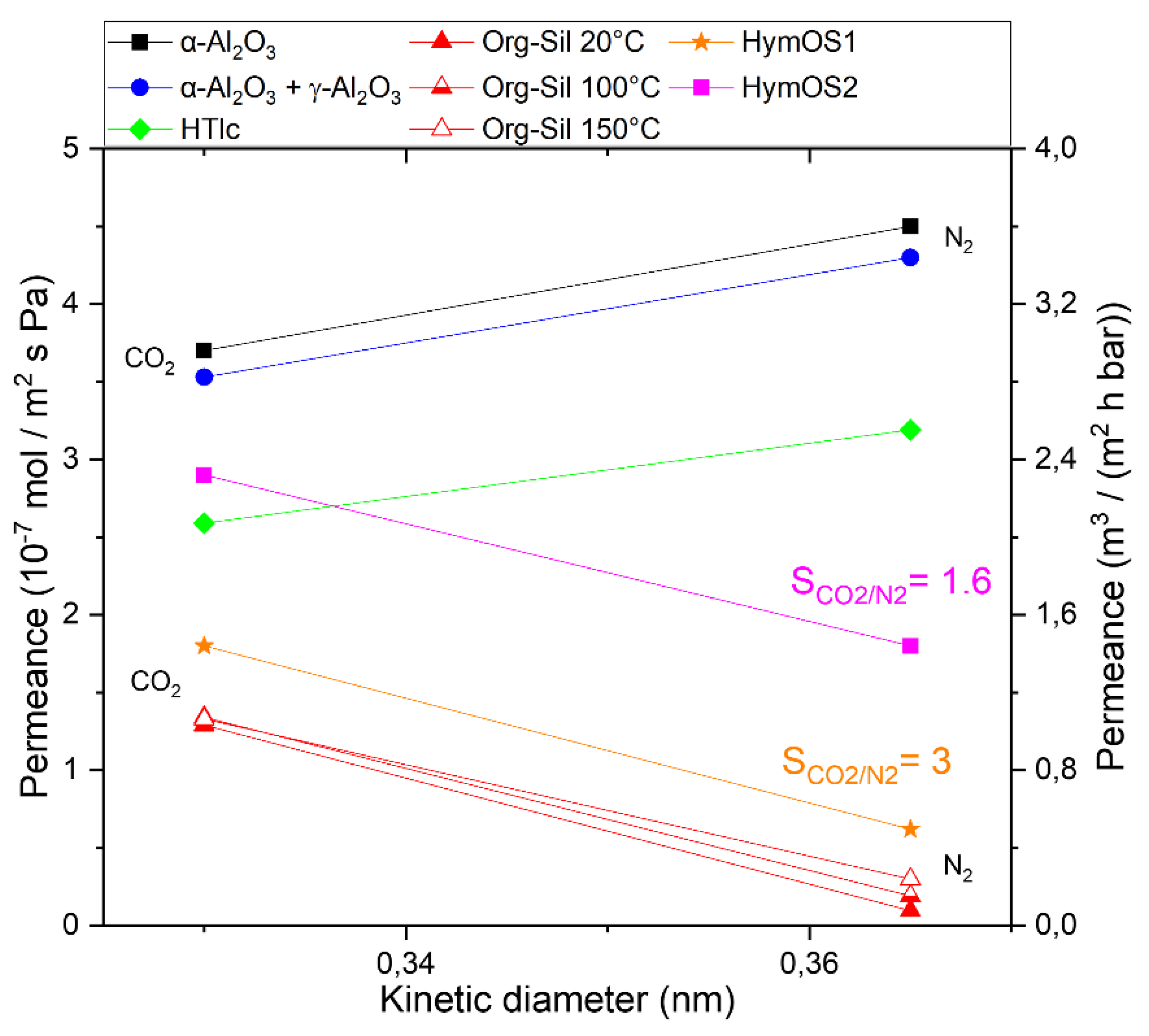
Figure 7.
Visualization of the total MMM permeance described in Equation (2) for CO2 and Equation (3) for N2 as a function of the added HTlc content. The total permeance and the permeances for different mass transport mechanisms that comprise the total permeance are given in dark for CO2 and blue for N2. The resulting selectivity is shown in red.
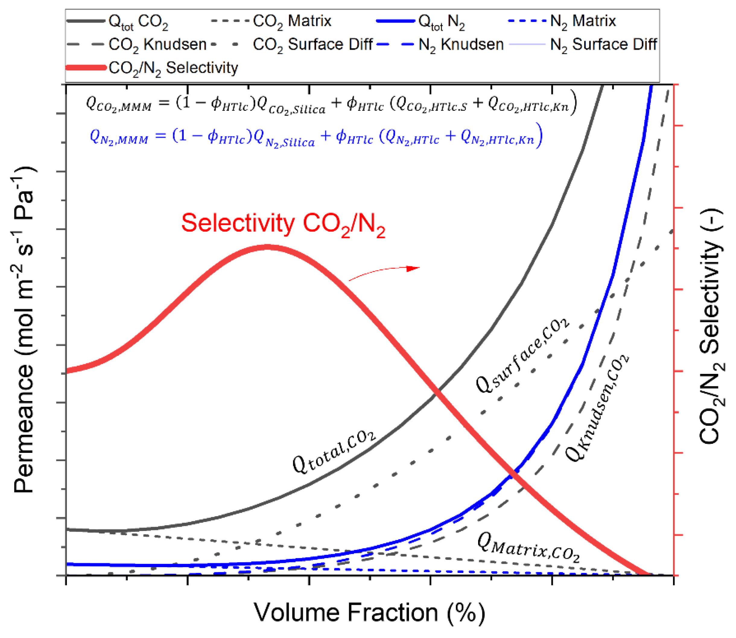

Table 1.
Calculated single gas, stand-alone single layer permeances, permeabilities, and respective permselectivities at 25°C. Measured layer thickness derived from SEM images are 2,2 mm for α-Al2O3, 4 µm for γ-Al2O3, 100 nm for Org-Sil, HymOS1 and HymOS2.
Table 1.
Calculated single gas, stand-alone single layer permeances, permeabilities, and respective permselectivities at 25°C. Measured layer thickness derived from SEM images are 2,2 mm for α-Al2O3, 4 µm for γ-Al2O3, 100 nm for Org-Sil, HymOS1 and HymOS2.
| Single Layer | Permeance (10-7 mol (m2 s Pa)-1) |
Permeability /10-14 mol (m s Pa)-1 |
Perm- Selectivity CO2/N2 |
||
|---|---|---|---|---|---|
| N2 | CO2 | N2 | CO2 | ||
| α-Al2O3 | 4.5 | 3.6 | 99000 | 79200 | 0.80 |
| γ-Al2O3 | 36 | 61.2 | 1440 | 2448 | 1.7 |
| HTlc | 14.7 | 12.3 | 29.52 | 24.6 | 0.83 |
| Organo- silica |
0.10 | 2.1 | 0.10 | 2.10 | 20.52 |
| HymOS1 | 0.73 | 3.83 | 0.73 | 3.83 | 5.2 |
| HymOS2 | 3.27 | 19.72 | 3.27 | 19.72 | 6 |
Disclaimer/Publisher’s Note: The statements, opinions and data contained in all publications are solely those of the individual author(s) and contributor(s) and not of MDPI and/or the editor(s). MDPI and/or the editor(s) disclaim responsibility for any injury to people or property resulting from any ideas, methods, instructions or products referred to in the content. |
© 2024 by the authors. Licensee MDPI, Basel, Switzerland. This article is an open access article distributed under the terms and conditions of the Creative Commons Attribution (CC BY) license (http://creativecommons.org/licenses/by/4.0/).
Copyright: This open access article is published under a Creative Commons CC BY 4.0 license, which permit the free download, distribution, and reuse, provided that the author and preprint are cited in any reuse.


