

Submitted:
21 May 2024
Posted:
21 May 2024
You are already at the latest version
Abstract
Quantum-dot cellular automata (QCA) is an emerging transistor-less field-coupled nanocomputing (FCN) approach to ultra-scale ‘nanochip’ integration. In QCA, to represent digital circuitry, electrostatic repulsion between electrons and the mechanism of electron tunnelling in quantum dots are used. QCA technology can surpass conventional complementary metal-oxide semiconductor (CMOS) technology in terms of clock speed, reduced occupied chip area, and energy efficiency. To develop QCA circuits, irreversible majority gates are typically used as the primary components. Recently, some studies have introduced reversible design techniques, using reversible majority gates as the main building block, to develop ultra-energy efficient QCA circuits. However, this approach resulted in time delays, an increase in the number of QCA cells used, and an increase in the chip area occupied. This work introduces a novel hybrid design strategy employing QCA irreversible, reversible, and partially reversible gates to establish an optimal balance between power consumption, delay time, and occupied area. The hybrid technique allows the designer to have more control over the circuit characteristics to meet different system needs. A combination of reversible, irreversible, and innovative partially reversible majority gates is used in the proposed hybrid design method. We have evaluated the hybrid design method by examining the half-adder circuit as a case study. We have developed four hybrid QCA half-adder circuits, each of which simultaneously incorporates various types of majority gates. The QCADesigner-E 2.2 simulation tool was used to simulate the performance and energy efficiency of the half-adders. This tool provides numerical results for the circuit input/output response and heat dissipation at the physical level, within a microscopic quantum mechanical model.
Keywords:
Quantum-dot cellular automata (QCA)
; Hybrid
; Half-adder
; QCADesigner-E
1. Introduction
Quantum-dot cellular automata (QCA) is a field-coupled nanocomputing (FCN) approach in which information is encoded as the polarisation of each cell in terms of the orientation of the electrons in a quantum dot [1]. Theoretically, QCA offers several advantages over complementary metal-oxide semiconductor (CMOS) technology in the development of digital circuits, including lower power consumption, higher speed, and higher integration density. The QCA concept for encoding binary information relies on QCA cells, which consist of four quantum dots and two electron charges arranged in an antipodal orientation [2]. The information is subsequently propagated to neighbouring cells via Coulombic electrostatic forces [3], which results in energy-efficient digital circuits with no current flow and no associated ohmic dissipation.
The process of designing QCA digital circuits typically entails the use of majority gates and inverters. An 'AND' or 'OR' gate can be generated by assigning a binary value of '0' or '1' to one of the majority gate inputs, respectively. Thus, the incorporation of majority gates and inverters enables the development of different digital circuits. QCA technology allows the construction of computer systems by building complex Boolean functions using inverters and majority gates. The QCA-based computer system improvement is particularly significant for fields in which speed, area, and power consumption are critical considerations. The standard QCA inverter is reversible due to the one-to-one connection between the input and output signals, as shown in Figure 1a. Conversely, the conventional majority gate is irreversible because of its configuration, which includes three inputs and only a single output pin, as depicted in Figure 1b.
The conventional irreversible QCA majority gate has been utilised as a fundamental component in several studies to develop various QCA digital circuits [4,5,6]. According to the second law of thermodynamics, information loss typically occurs in conventional irreversible computing methods, accompanied by heat dissipation, in which bits are irreversibly erased within the logic circuitry, known as Landauer’s limit [7]. The heat dissipation due to the information loss is quantified as kBTln2 joules per bit erased, where kB is the Boltzmann constant and T is the temperature [7]. The experimental verification of Landauer's theory has confirmed the existence of a physical limit to irreversible computing [8,9,10]. In CMOS technology, for example, the amount of energy dissipated due to information loss is approximately fifty times greater than Landauer’s lower limit [11].
To perform computing operations with ultralow energy dissipation below kBTln2, reversible logic operations are essential, with each input signal having a unique associated output pin [12]. Theoretically, reversible computing operations, in which reversibility is maintained from the logic synthesis level down to the physical layout level, result in no information loss and consequently zero energy dissipation into the environment [13]. Several studies have simulated QCA digital circuits with extremely low energy dissipation by utilising logically and physically reversible design techniques [14,15,16,17,18]. These reversible design techniques use reversible majority gates, which recycle the input signals, as the main building blocks. Figure 2a shows the logic symbol of the reversible majority gate, while Figure 2b shows the QCA layout.
The implementation of QCA circuits with logically and physically reversible approaches results in significantly less energy dissipation than that employing irreversible circuits [12]. However, reversible design methods often lead to time delays, increased area usage, and the use of more QCA cells, i.e., increases in circuit cost metrics [19]. This study introduces an innovative hybrid design method that provides a compromise between energy-efficiency-oriented reversible design methods and cost-efficiency-oriented irreversible design methods. The hybrid design strategy described here utilises a combination of reversible and irreversible majority gates, as well as the novel partially reversible majority gate, developed in this study. The performance of the hybrid design strategy is examined using the half-adder circuit as a case study. Four different half-adder designs are developed in this research, each utilising a specific combination of three types of majority gates. The information loss, energy dissipation, speed of data transmission, occupied area, number of QCA cells used, and circuit cost of the introduced half-adder designs, are comprehensively examined. A comparison of the results shows that the hybrid design approach provides the designer with high control over the circuit characteristics, allowing an optimal trade-off between circuit cost and energy efficiency to be achieved, to meet the requirements of different systems.
The subsequent sections of this paper are structured as follows: Section 2 elucidates the underlying principle of the proposed hybrid design method. Section 3 presents a case study on the hybrid QCA design method for the half-adder circuit. Section 4 presents the simulation results for the half-adder designs. Section 5 discusses the simulation results of the hybrid QCA half-adders. Section 6 provides the conclusions of this study.
2. Hybrid Design Method
Power consumption, operating frequency, and area are key specifications that need to be considered when designing digital integrated circuits (ICs) to ensure that the circuit meets its intended performance, efficiency, and application requirements [20]. Current QCA design methodologies use a single form of a majority gate, either reversible or irreversible, to build QCA digital circuits. Irreversible majority gates are employed in QCA circuits when the primary consideration is cost-effectiveness in terms of the operating frequency and occupied area. Conversely, reversible majority gates are employed in QCA circuits when the primary emphasis is on power efficiency. Most applications require circuits that simultaneously demonstrate optimal levels of efficiency in terms of power consumption, time, and area. This study introduces an innovative hybrid design method that represents a compromise solution between energy-efficiency-oriented reversible design methods and cost-efficiency-oriented irreversible design methods.
In the hybrid design method discussed in this study, three types of majority gates are simultaneously used to develop QCA digital circuits. The hybrid design method utilises reversible and irreversible majority gates, along with a novel partially reversible majority gate, as the primary building blocks for creating hybrid QCA circuits. The key advantage of the proposed hybrid design method is its ability to provide high control over the circuit characteristics during the circuit design process. The ultimate function of the circuit determines the number of majority gates employed for each of the three types of majority gates.
For example, if energy efficiency is prioritised for the circuit while maintaining an appropriate level of cost efficiency, then the number of reversible majority gates must surpass the number of irreversible and partially reversible majority gates in the circuit. In contrast, if minimising area costs while maintaining a suitable level of energy efficiency is the focus, then the circuit must include more irreversible majority gates than reversible and partially reversible majority gates. To establish the optimal trade-off between energy dissipation and circuit cost, the use of a greater proportion of partially reversible majority gates than of reversible and irreversible majority gates is advisable. Thus, the hybrid design method allows the designer to determine the number of different types of majority gate in the circuit, i.e., reversible, partially reversible, or irreversible, thereby providing significant control over the circuit characteristics throughout the design process.
To execute the hybrid design strategy, we first developed an innovative, partially reversible majority gate. Only a few previous studies have investigated the partially reversible design concept [21,22,23]. In 2011, Ottavi et al. introduced a partially reversible method to balance the energy dissipation, delay time, and area used through the inclusion of memory stages and a control mechanism, which resembled a pipeline [21]. However, this strategy is less efficient when more pipeline clock zones are utilised [22]. In 2019, Chaves et al. presented an alternative approach to designing partially reversible circuits in FCN technologies by considering layout alterations rather than timing modifications [23]. This approach relies on recycling one input signal for the logic gate. To our knowledge, this method has not yet been validated for QCA logic gate design.
For the first time, this study shows how to use a partially reversible design method to make a novel three-input partially reversible QCA majority gate. Figure 3 shows the proposed three-input partially reversible QCA majority gate that recycles one input signal. The logic symbol diagram of this partially reversible majority gate is shown in Figure 3a, and the QCA layout design is shown in Figure 3b. The functionality of the three-input partially reversible majority gate is determined by setting one of its inputs to a binary value of 0 or 1, which determines whether the gate operates as an AND gate or an OR gate, respectively. For example, when the input C is set to 0, the gate is an AND gate, whereas when the input C is set to 1, the gate is an OR gate.
The novel partially reversible majority gate, as well as the conventional irreversible and reversible majority gates, are all used in the proposed hybrid design method to create hybrid QCA digital circuits.
Data synchronisation is essential for precise data transmission and accurate operation in digital logic circuits [24]. To manage the timing of QCA circuits, external clocks are employed to precisely adjust the tunnelling barriers between QCA cells [1,25,26]. This study integrates the universal, scalable, and efficient (USE) clocking scheme [26] with the proposed hybrid design method to synchronise the data transmission of hybrid QCA digital circuits. The USE clocking scheme has notable adaptability, so it can effectively meet the requirements of the designed QCA circuit. These requirements include the integration of feedback channels with various loop sizes, the establishment of common cell libraries, and simplified routing. The USE clocking system is divided into four time zones, designated 1 to 4. Each time zone is composed of 25 QCA cells arranged in a five-by-five pattern, and each time zone corresponds to a unique period. A complete clock cycle is formed with these four time zones. Further details can be found in previous works [27,28,29,30].
In addition, wire crossing is a crucial issue in digital circuits. The proposed hybrid design method employs the multilayer approach developed by Bajec and Pecar [31] to address this issue.
3. Design of Hybrid QCA Half-Adder Circuits
A comprehensive case study is a valuable tool for demonstrating the practical applicability and effectiveness of the proposed hybrid design methodology in designing QCA digital circuits. In very large-scale integration (VLSI) systems, the half-adder circuit is a fundamental building block for arithmetic operations. The circuit adds two single-bit binary numbers and generates the sum (S) and carry (C) outputs. This section presents the design of the half-adder circuit as a case study to demonstrate the effectiveness of the innovative hybrid design methodology.
The type and number of majority gates used to design a QCA circuit are critical aspects that can influence circuit specifications. In previous studies, only one type of majority gate, either the reversible majority gate [14,18] or the irreversible majority gate [32,33,34,35,36,37], was used in the design of QCA half-adder circuits. In terms of the number of majority gates used for designing the half-adder circuit, a few prior studies used five majority gates [34,36], whereas others used four majority gates [14,18,37]. In this case study, we developed hybrid QCA half-adder circuits by simultaneously using three types of majority gates: reversible, irreversible, and partially reversible. Furthermore, the total number of majority gates used to build these half-adders was four. By using the three different types of majority gates to represent the four majority gates that constitute the half-adder, we can obtain a total of 81 different possible combinations that can represent the same QCA half-adder circuit. Despite all these designs having the same functionality, each has unique specifications. The number of majority gates for each of the three types of majority gates used in the circuit determines the energy consumption, delay time, and area occupied. Thus, by changing the types of majority gates included in the circuit, the designer can achieve a higher level of control over the final specifications of the circuit.
Describing the 81 possible combinations that represent the hybrid QCA half-adder circuit is a large design configuration space. This section takes four distinct combinations of majority gates to design four different hybrid QCA half-adder circuits as a sample of the full design configuration space. These four versions are sufficient to effectively illustrate the concept of the hybrid design methodology. The main difference between these four hybrid QCA half-adder circuits lies in the number of reversible, partially reversible, and irreversible majority gates employed in designing the half-adder circuit. The first proposed design of a hybrid QCA half-adder uses three fully reversible majority gates and one irreversible majority gate. The second proposed design uses two fully reversible majority gates, one partially reversible majority gate, and one irreversible majority gate. The third proposed design consists of two fully reversible and two irreversible majority gates. The fourth proposed design consists of two partially reversible and two irreversible majority gates. Table 1 lists the technological parameters used to develop the novel hybrid QCA half-adder circuits. To prevent wire junction issues, a multilayer approach with three distinct layers was used. Furthermore, we employed the USE clocking technique to synchronise the data transmission.
Equation 1 describes the Boolean expression, and Table 2 presents the truth table of the proposed hybrid QCA half-adder circuits.
3.1. First Hybrid QCA Half-Adder Design (Three Fully Reversible and One Irreversible Majority Gate)
Figure 4 presents the first developed design of a hybrid QCA half-adder. The circuit uses three fully reversible majority gates (M1, M2, and M3) and one irreversible majority gate (M4). Figure 4a depicts the logic synthesis of this hybrid half-adder circuit, whereas Figure 4b displays the QCA layout. The circuit consists of 117 QCA cells, which occupy an area of 0.16 µm2. The measured latency is 11 clock phases, which is equal to 2.75 clock cycles.
3.2. Second Hybrid QCA Half-Adder Design (Two Fully Reversible, One Partially Reversible and One Irreversible Majority Gate)
Two fully reversible majority gates (M1 and M2), one partially reversible majority gate (M3), and one irreversible majority gate (M4) make up the second hybrid QCA half-adder circuit. Figure 5a shows the logic synthesis of this hybrid half-adder circuit, whereas Figure 5b shows the QCA layout. In the second design, the only modification compared with the first design is the change in the reversibility of one majority gate, M3, from fully to partially reversible. Consequently, there is a 6% decrease in the number of QCA cells compared to the first design, resulting in a total of 110 QCA cells in the second design. However, the occupied area and delay time are consistent with those of the first design, with an area of 0.16 m2 and a delay of 11 clock phases, equivalent to 2.75 clock cycles.
3.3. Third Hybrid QCA Half-Adder Design (Two Fully Reversible, and Two Irreversible Majority Gate)
Figure 6 shows the third design for a hybrid QCA half-adder. The circuit is composed of two fully reversible majority gates (M1 and M2) and two irreversible majority gates (M3 and M4). Figure 6a depicts the logic synthesis of the third hybrid QCA half-adder circuit, whereas Figure 6b displays the QCA layout. In the third design, the only modification compared with the second design is the change in the reversibility of one majority gate, M3, from partially reversible to irreversible. As a result, the number of QCA cells decreases by 8.2%, the occupied area decreases by 18.8%, and the speed improves by 9% compared to those of the second design. For the third hybrid QCA half-adder, 101 QCA cells are used to build the circuit, which occupy an area of 0.13 µm2. The measured latency is 10 clock phases, which is equal to 2.5 clock cycles.
3.4. Fourth Hybrid QCA Half-Adder Design (Two Partially Reversible, and Two Irreversible Majority Gate)
Figure 7 presents the fourth developed design of a hybrid QCA half-adder. Two partially reversible majority gates (M1 and M2) and two irreversible majority gates (M3 and M4) are used in the circuit. Figure 7a displays the logic synthesis of this hybrid half-adder circuit, while Figure 7b displays the QCA layout. The fourth design differs from the third design in that the reversibility of two majority gates, M1 and M2, changes from partially reversible to irreversible. As a result, compared with those of the third design, the number of QCA cells decreases by 11.9%, the occupied area decreases by 7.7%, and the speed significantly improves by 60%. The fourth hybrid QCA half-adder consists of 90 QCA cells, which occupy an area of 0.12 µm2. The measured latency is 4 clock phases, which is equal to 1 clock cycle.
4. Simulation Results
This section offers an in-depth examination of the hybrid QCA half-adder circuits discussed in Section 3, focusing on their performance reliability, information loss, energy dissipation, and circuit cost.
4.1. Performance Evaluation
We used the QCADesigner-E 2.2 simulation tool to simulate the input/output behaviour of the four presented hybrid QCA half-adder designs. QCADesigner-E 2.2 uses a microscopic quantum mechanical model of tunnelling inside a QCA cell, along with the intra- and intercell electrostatic interactions, and a density matrix description of energy dissipation within a phenomenological model [30]. Our earlier paper [17] provides more details on the energy dissipation treatment within the quantum mechanical coherence vector formalism for the density matrix.
To validate the reliability of the innovative hybrid design method in developing QCA digital circuits, we compared the simulated waveforms with the values in the truth table of the half-adder circuit given in Table 2.
4.1.1. Simulated Waveforms of the First Hybrid (Three Fully Reversible and One Irreversible Majority Gate) QCA Half-Adder Design
4.1.2. Simulated Waveforms of the Second Hybrid (Two Fully Reversible, One Partially Reversible and One Irreversible Majority Gate) QCA Half-Adder Design
4.1.3. Simulated Waveforms of the Third Hybrid (Two Fully Reversible, and Two Irreversible Majority Gate) QCA Half-Adder Design
4.1.4. Simulated Waveforms of the Fourth Hybrid (Two Partially Reversible, and Two Irreversible Majority Gate) QCA Half-Adder Design
4.2. Information Dissipation Calculation
This section presents calculations of the information dissipation for the hybrid QCA half-adder circuits considered. Shannon's entropy is a key concept in information theory that quantifies the level of information contained within a set of possible outcomes [38]. Various disciplines, including telecommunications, encryption, and data compression, commonly employ Shannon's entropy. Thus, Shannon's entropy was used to calculate the total amount of information dissipated in each of the four hybrid QCA half-adder circuits presented in this study. The formula for Shannon's entropy for a discrete random variable with possible values of is given by Equation 2:
where is the probability of outcome and is the logarithm of the two-bit entropy.
To determine the amount of information lost in each gate, we measured the difference between Shannon's entropy for the probability distributions of the initial and final states of the gates, i.e., , where the entropy of is the summation of the contributions of all initial states and the entropy of is the summation of the contributions of all final states. Finally, the total information dissipated in a circuit is computed by summing the information lost for the gates comprising the circuit using Equation 3.
where is the number of gates used to construct the circuit.
4.2.1. Information Dissipation of the First Hybrid (Three Fully Reversible and One Irreversible Majority Gate) QCA Half-Adder Design
First, we calculated Shannon's entropy using Equation 2 to define the amount of information lost for each gate in the first design. This design consists of three fully reversible majority gates (M1, M2, and M3) and one irreversible gate (M4), as illustrated in Figure 4. Table 3 provides a comprehensive breakdown of Shannon's entropy calculations for all gates in the first design. Tables 3a, 3b, and 3c show that the fully reversible majority gates M1, M2, and M3 recycle all the information without any information loss. Table 3d, in contrast, shows that the irreversible majority gate M4 loses 0.5 bits of information. Next, we used Equation 3 to compute the total amount of information lost in the first design. Equation 3 aggregates the Shannon's entropy lost from all the majority gates that form the circuit. According to Table 3, the information loss of the first design is solely attributable to the irreversible majority gate M4. Thus, the total amount of information lost in the first design is equivalent to the M4 information loss, which is 0.5 bits.
4.2.2. Information Dissipation of the Second Hybrid (Two Fully Reversible, One Partially Reversible and One Irreversible Majority Gate) QCA Half-Adder Design
Initially, we calculated Shannon's entropy using Equation 2 to define the amount of information lost for each gate in the second design. This design consists of two fully reversible majority gates (M1 and M2), one partially reversible gate (M3), and one irreversible gate (M4), as illustrated in Figure 5. Table 4 provides a comprehensive breakdown of Shannon's entropy calculations for all gates in the second design. Tables 4a and 4b show that the fully reversible majority gates M1 and M2 recycle all the information without any information loss. In contrast, Tables 4c and 4d show that the partially reversible majority gate M3 and the irreversible majority gate M4 lose 0.5 bits of information each. According to Table 4, the information loss of the second design is attributable to the partially reversible majority gate M3 and irreversible majority gate M4. Thus, the total amount of information lost in the second design is equivalent to the summation of the M3 and M4 information losses, which is 1 bit.
4.2.3. Information Dissipation of the Third Hybrid (Two Fully Reversible, and Two Irreversible Majority Gate) QCA Half-Adder Design
First, we calculated Shannon's entropy using Equation 2 to define the amount of information lost for each gate in the third design. This design consists of two fully reversible majority gates (M1 and M2) and two irreversible majority gates (M3 and M4), as illustrated in Figure 6. Table 5 provides a comprehensive breakdown of Shannon's entropy calculations for all gates in the third design. Tables 5a and 5b demonstrate that the fully reversible majority gates M1 and M2 recycle all the information without any information loss. In contrast, Tables 5c and 5d show that the irreversible majority gates M3 and M4 lose 1.19 bits and 0.5 bits of information, respectively. Next, we used Equation 3 to compute the total amount of information lost in the third design. According to Table 4, the information loss of the third design is attributable to the irreversible majority gates M3 and M4. Thus, the total amount of information lost in the third design is equivalent to the summation of the M3 and M4 information losses, which is 1.69 bits.
4.2.4. Information Dissipation of the Fourth Hybrid (Two Partially Reversible, and Two Irreversible Majority Gate) QCA Half-Adder Design
Initially, we calculated Shannon's entropy using Equation 2 to define the amount of information lost for each gate in the fourth design. This design consists of two partially reversible majority gates (M1 and M2) and two irreversible majority gates (M3 and M4), as illustrated in Figure 7. Table 6 provides a comprehensive breakdown of Shannon's entropy calculations for all gates in the fourth design. Tables 5a, 5b, 5c, and 5d show that the partially reversible majority gates M1 and M2 and the irreversible majority gates M3 and M4 lose 0.5, 0.5, 0.5, and 1.19 bits of information, respectively. Next, we used Equation 3 to compute the total amount of information lost in the fourth design. According to Table 4, the information loss of the fourth design is attributable to the partially reversible majority gates M1 and M2 and irreversible majority gates M3 and M4. Thus, the total amount of information lost in the fourth design is equivalent to the summation of the M1, M2, M3 and M4 information losses, which is 2.69 bits.
4.2.5. Summary of Information Dissipated in the Hybrid QCA Half-Adder Designs
Table 7 presents a summary of the information dissipation for the four hybrid half-adder designs discussed earlier in this section.
Table 7 demonstrates that a reduction in circuit reversibility can lead to an increase in information loss. Simply stated, replacing a reversible majority gate with an irreversible or partially reversible gate, or replacing a partially reversible majority gate with an irreversible gate will result in greater loss of information in the circuit.
The first hybrid QCA half-adder design uses three fully reversible majority gates (M1, M2, and M3) and one irreversible majority gate (M4), resulting in a loss of 0.5 bits of information.
The second hybrid QCA half-adder design uses two fully reversible majority gates (M1 and M2), one partially reversible majority gate (M3), and one irreversible majority gate (M4). The only alteration compared to the first design is a change in the reversibility of the third majority gate (M3) from fully reversible to partially reversible. The substitution of the third reversible majority gate (M3) with a partially reversible gate results in a twofold increase in information dissipation, from 0.5 bits to 1 bit, compared to the first design.
The third hybrid QCA half-adder design uses two fully reversible majority gates (M1 and M2) and two irreversible majority gates (M3 and M4). The only change from the second design is the substitution of the third majority gate (M3). The third majority gate (M3) has changed from being partially reversible in the second design to becoming irreversible in the third design. In comparison with the second design, changing the third majority gate (M3) results in an increase in information loss, from 1 bit to 1.69 bits. This implies a 0.69-bit increase in information loss, which equates to 69%. Compared to the first design, the third design shows an increase in information loss, from 0.5 bits to 1.69 bits. This implies a 1.19-bit increase in information loss, which equates to 238%.
The fourth hybrid QCA half-adder design uses two partially reversible majority gates (M1 and M2) and two irreversible majority gates (M3 and M4). The fourth design exhibits a 1-bit increase in information dissipation compared to the third design, rising from 1.69 bits to 2.69 bits, which corresponds to a 59% increase. In comparison to the second design, the fourth design has demonstrated a 1.69-bit increase in information dissipation, representing a 169% increase from 1 bit to 2.69 bits. Compared to the first design, the fourth design has seen a substantial rise in information dissipation with a 2.19-bit increase, equivalent to a 438% increase from 0.5 bits to 2.69 bits.
4.3. Energy Dissipation Simulation
Precise calculations of energy dissipation are essential for evaluating the efficiency of QCA circuits. In QCA, energy efficiency is crucial because it enables a promising solution for realising low-power computing, which is a major challenge in contemporary electronic architecture. An in-depth assessment of circuit energy management is essential for improving circuit design and performance since the circuit involves the dissipation of energy between the clock, cells, and environment.
This study has used the QCADesigner-E 2.2 [30] simulation tool to evaluate the energy dissipation in hybrid QCA half-adder circuits. QCADesigner-E extends the well-known QCA simulation tool QCADesigner specifically for detailed analysis of energy dissipation within QCA circuits. This tool provides a mechanism for evaluating the energy dissipation to the surrounding environment by solving the ordinary differential equations for the coherence vector description of the density matrix [30]. A small time step helps reduce simulation errors, leading to more accurate results. The time step (Tstep) for each iteration of the simulation was set to 0.1 fs in this study. This led to a simulation error tolerance of approximately 5%. This approach strikes a balance between the need for precision and the practical aspects of the simulation run time, ensuring that the simulation remains computationally feasible. This value is a practical threshold taken, to reduce the CPU time for numerical simulations. However, the time step is low enough to ensure that the results are still meaningful, in terms of having the necessary degree of numerical energy conservation, and thus being useful for design evaluation. Managing and understanding these errors is critical for improving simulation models and interpreting simulation results. Table I presents a comprehensive description of the technological and simulation parameters used in this study to simulate energy dissipation.
Table 8 shows the simulation results for the energy dissipation of the innovative, partially reversible QCA majority gate. Additionally, Table 8 illustrates the energy losses associated with both the fully reversible and irreversible majority gates commonly used in QCA digital circuit construction. The simulation results show that the fully reversible QCA majority gate reported in reference [18] uses 93% less energy than the partially reversible QCA majority gate suggested in this work. Additionally, the partially reversible QCA majority gate introduced in this study consumes 92% less energy than the conventional irreversible majority gate.
The energy dissipation simulation results of the novel hybrid QCA half-adder circuits are shown in Table 9. The energy dissipation values of all the designs were simulated using QCADesigner-E by employing the simulation and technological parameters presented in Table I.
The simulation findings on the energy dissipation in the hybrid QCA half-adder circuits indicate that the use of majority gates with a higher level of reversibility, which can recycle more input data, can lead to a decrease in the energy dissipation of the QCA circuit. To compare the energy dissipation results of the hybrid QCA half-adder circuits under study, we have calculated the average energy dissipation values. The average energy dissipation represents the average energy dissipation value across all input signal combinations in a circuit. Table 9 shows the total and average energy dissipation calculations for the proposed hybrid QCA half-adder circuits.
The first design of the QCA half-adder circuit utilises three reversible majority gates (M1, M2, and M3) and one irreversible majority gate (M4), resulting in an average energy dissipation of 0.314 meV per operation.
The average energy dissipation of the hybrid QCA half-adder circuit increases by 97% to 0.617 meV when the third majority gate (M3) changes from fully reversible in the first design to partially reversible in the second design.
In the third design of the hybrid QCA half-adder circuit, the energy dissipation further increases. The average energy dissipation in the third design increases by 6.7% to 0.664 meV when the third majority gate (M3) is changed from partially reversible in the second design to irreversible in the third design.
In the fourth design of the hybrid QCA half-adder circuit, there is a significant increase in energy dissipation. Compared to the third design, the average energy dissipation increases by 107% to 1.374 meV. The fourth hybrid QCA half-adder design includes two partially reversible majority gates (M1 and M2) and two irreversible majority gates (M3 and M4), and it does not include any fully reversible majority gates, which can explain the significant increase in energy dissipation in the fourth design.
4.4. Cost Calculation
The circuit cost encompasses several aspects, including the complexity of the design and manufacturing process and the operational cost associated with the delay time. The delay time, number of logic gates, and number of crossovers are essential metrics for measuring the circuit performance, design complexity, and fabrication difficulty of a QCA circuit.
The cost function can be computed as a figure-of-merit (FOM) to evaluate the characteristics of QCA circuits [19,39]. Currently, there are two recognised cost functions for calculating the cost of QCA circuits. The first cost function is employed to calculate the cost of designs utilising three-input majority gates [19], while the second cost function is utilised to evaluate the cost of designs employing five-input majority gates [39]. Thus, the costs of hybrid half-adder circuits, which utilise three-input majority gates, can be calculated using the first cost function [19]. The cost function is shown in Equation 4.
where represents the number of three-input majority gates, represents the number of inverters, represents the number of crossovers, and represents the delay time of the circuit measured in clock phases. In addition, the variables , , and represent the powers assigned to the number of majority gates, number of crossovers, and delay time, respectively. Typically, we assign a weight of 1 to the number of inverters because they have a limited impact on the complexity of QCA circuits.
The cost function prioritises different metrics based on the , , and values. For instance, if speed should be prioritised, then the delay measure might be assigned greater significance by increasing . If the primary concern is the manufacturing cost, then should be greater than and . Consequently, the weight values can be altered based on the main design goal. In most scenarios, both the number of majority gates M and the number of crossovers C are considered important [19]. Thus, the following cost function is typically used:
Table 10 presents the cost calculation results of the hybrid QCA half-adder circuits obtained using Equation 5.
The cost calculations for the hybrid QCA half-adder circuits demonstrate that using majority gates with lower reversibility can effectively decrease the circuit's overall cost. The first design of the hybrid QCA half-adder circuit utilises three reversible majority gates (M1, M2, and M3) and one irreversible majority gate (M4), resulting in a total cost of 253. The second design modified the third majority gate (M3) from being fully reversible to being partially reversible. As a result, the circuit cost decreased by 13%, from 253 to 220. The third half-adder design has changed the third majority gate (M3) to be irreversible. As a result, the circuit cost has decreased by an additional 9%, from 220 to 200, compared to the second design. The fourth hybrid QCA half-adder design uses two partially reversible majority gates (M1 and M2) and two irreversible majority gates (M3 and M4). Importantly, the fourth design does not use any fully reversible majority gates. As a result, the fourth hybrid QCA half-adder design demonstrates a significant reduction in circuit cost, dropping 56% from 200 to 88 compared to the third design.
5. Discussion
This section provides a comprehensive analysis of the simulation findings for the four hybrid QCA half-adder circuits considered. The four hybrid QCA half-adder designs demonstrate various degrees of reversibility. This is attributed to the utilisation of diverse combinations of distinct types of majority gates, including irreversible, partially reversible, and fully reversible majority gates. The analysis of the simulation findings elucidates the direct relationship between the level of reversibility, amount of information lost, quantity of energy dissipated into the environment, and circuit cost.
The thermodynamic principle and information theory confirm the intrinsic correlation between reversibility, information loss, and energy dissipation in computer circuits [40]. The capacity to recycle input information directly correlates with the level of reversibility, where recycling more input information increases the level of reversibility and thus reduces data erasure [12]. Put succinctly, QCA circuits with a greater capacity to reuse input information are intrinsically more reversible because they preserve a greater amount of information throughout their processes. Therefore, if a circuit's level of reversibility decreases, in terms of a reducing number of reversible gates, information loss increases. Figure 12 shows that the information loss and energy dissipation steadily increase as the reversibility level decreases, in the hybrid QCA half-adders moving from the first design to the second, third, and fourth designs.
A reduction in the circuit reversibility can result in a decrease in the circuit cost. However, reducing the circuit reversibility to achieve a lower cost can result in an increase in information loss and energy dissipation. Figure 13 shows that the first hybrid QCA half-adder design, which has the highest level of reversibility among the four considered designs, also has the highest cost compared to the other three designs. As the degree of reversibility decreases, the circuit cost gradually decreases for the second, third, and fourth designs.
The first half-adder circuit, which has the highest level of reversibility compared to the other half-adder circuits developed in this study, experiences information loss of 0.5 bits combined with energy dissipation of 0.314 meV. This is accomplished by employing three fully reversible majority gates and one irreversible majority gate. The cost of this half-adder circuit is 253.
The second design exhibits a twofold increase in information loss, from 0.5 bits to 1 bit, compared to the first design. Simultaneously, there is a 96.5% increase in energy dissipation, from 0.314 meV to 0.617 meV, compared to the first design. The reason for this change is that the reversibility level of the third majority gate decreases from fully reversible in the first design to partially reversible in the second design. Conversely, the cost of the second design decreases by 13%, from 253 to 220, compared to that of the first design.
In the third design, the reversibility is decreased more by replacing the third partially reversible majority gate with an irreversible gate. This results in an additional 69% increase in information loss, from 1 bit to 1.69 bits, compared to the second design. This increase is accompanied by a 7.6% increase in energy dissipation, from 0.617 meV to 0.664 meV, compared to the second design. However, the third design enables an additional 9% cost improvement, from 220 to 200, compared to the second design.
The reversibility of the fourth hybrid QCA half-adder design also decreases. In the fourth design, two partially reversible and two irreversible majority gates are employed, and this design does not include any fully reversible majority gates. This results in a 59% increase in information loss, from 1.69 bits to 2.69 bits, compared to the third design. The energy dissipation also increases compared to that of the third design by 113%, from 0.644 meV to 1.374 meV. Conversely, the cost of the fourth design further improves by 56%, from 200 to 88, compared to that of the third design.
6. Conclusions
This work presents an innovative hybrid design method for developing QCA digital circuits. The hybrid design method uses a combination of irreversible, partially reversible, and fully reversible majority gates, as the basic building blocks. The hybrid design method offers a significant degree of flexibility in controlling the QCA circuit metrics of chip power, speed, and area, during the design development process. Thus, the designer can establish an optimal balance between the QCA circuit power, speed, and area tailoring the circuit to meet various system requirements.
The reliability of the hybrid design method was validated using the half-adder circuit as a case study. Four hybrid QCA half-adder circuits were designed, each of which used a specific combination of the three types of reversible, partially reversible, and irreversible majority gates. The major difference between these four hybrid QCA half-adder circuits lie in the actual numbers of reversible, partially reversible, and irreversible majority gates employed in designing the half-adder circuit. These four half adder circuits designs are enough to effectively illustrate the concept of the hybrid design methodology. The QCADesigner-E 2.2 simulation tool was used to simulate the performance and energy efficiency of the hybrid QCA half-adders, at the physical level. Shannon’s entropy was used to calculate the information lost for each half-adder circuit and the associated energy dissipation.
The simulation findings confirm that the hybrid design method can be used to control QCA circuit metrics, including information loss, energy dissipation, delay time, data transmission, and circuit cost, by manipulating the degree of reversibility. An increase in the circuit reversibility can negatively affect its cost. At the same time, the circuit energy efficiency can be improved by reducing the information loss and energy dissipation. Conversely, a decrease in the reversibility level of the circuit can positively affect its cost, while negatively affecting the energy efficiency, by increasing information loss and energy dissipation.
In future studies, the proposed hybrid design method can be used to develop more sophisticated combinational and sequential QCA digital circuits.
Author Contributions
All authors contributed to the conception and design of the study. The circuit design, simulation, and analysis were conducted by MA and examined by all authors. The first draft of the manuscript was written by MA, and all authors revised the manuscript. All authors approved the final manuscript.
Funding
This research received no external funding.
Data Availability Statement
The original contributions presented in the study.
Conflicts of Interest
The authors declare no conflicts of interest.
References
- Lent, C.S.; Tougaw, P.D. A device architecture for computing with quantum dots. Proceedings of the IEEE 1997, 85, 541–557. [Google Scholar] [CrossRef]
- Lent, C.S.; Tougaw, P.D.; Porod, W.; Bernstein, G.H. Quantum cellular automata. Nanotechnology 1993, 4, 49. [Google Scholar] [CrossRef]
- Tougaw, P.D.; Lent, C.S. Logical devices implemented using quantum cellular automata. Journal of Applied Physics 1994, 75, 1818–1825. [Google Scholar] [CrossRef]
- Ahmadpour, S.-S.; Mosleh, M.; Rasouli Heikalabad, S. The design and implementation of a robust single-layer QCA ALU using a novel fault-tolerant three-input majority gate. The Journal of Supercomputing 2020, 76, 10155–10185. [Google Scholar] [CrossRef]
- Ahmadpour, S.S.; Mosleh, M.; Rasouli Heikalabad, S. Robust QCA full-adders using an efficient fault-tolerant five-input majority gate. International Journal of Circuit Theory and Applications 2019, 47, 1037–1056. [Google Scholar] [CrossRef]
- Kassa, S.; Misra, N.K.; Ahmadpour, S.S.; Lamba, V.; Vadthiya, N. A novel design of coplanar 8-bit ripple carry adder using field-coupled quantum-dot cellular automata nanotechnology. The European Physical Journal Plus 2023, 138, 731. [Google Scholar] [CrossRef]
- Landauer, R. Irreversibility and heat generation in the computing process. IBM journal of research and development 1961, 5, 183–191. [Google Scholar] [CrossRef]
- Bérut, A.; Arakelyan, A.; Petrosyan, A.; Ciliberto, S.; Dillenschneider, R.; Lutz, E. Experimental verification of Landauer’s principle linking information and thermodynamics. Nature 2012, 483, 187–189. [Google Scholar] [CrossRef] [PubMed]
- Hong, J.; Lambson, B.; Dhuey, S.; Bokor, J. Experimental test of Landauer’s principle in single-bit operations on nanomagnetic memory bits. Science advances 2016, 2, e1501492. [Google Scholar] [CrossRef]
- Lent, C.S.; Orlov, A.; Porod, W.; Snider, G. Energy Limits in Computation; Springer: 2018.
- Agarwal, S.; Cook, J.; DeBenedictis, E.; Frank, M.P.; Cauwenberghs, G.; Srikanth, S.; Deng, B.; Hein, E.R.; Rabbat, P.G.; Conte, T.M. Energy efficiency limits of logic and memory. In Proceedings of the 2016 IEEE International Conference on Rebooting Computing (ICRC); 2016; pp. 1–8. [Google Scholar]
- DeBenedictis, E.P.; Frank, M.P.; Ganesh, N.; Anderson, N.G. A path toward ultra-low-energy computing. In Proceedings of the 2016 IEEE International Conference on Rebooting Computing (ICRC); 2016; pp. 1–8. [Google Scholar]
- Bennett, C.H. Logical reversibility of computation. IBM journal of Research and Development 1973, 17, 525–532. [Google Scholar] [CrossRef]
- Alharbi, M.; Edwards, G.; Stocker, R. Design and Simulation of Reversible Time-Synchronized Quantum-Dot Cellular Automata Combinational Logic Circuits with Ultralow Energy Dissipation. International Transaction Journal of Engineering, Management, & Applied Sciences & Technologies 2022, 13, 1–22. [Google Scholar] [CrossRef]
- Alharbi, M.; Edwards, G.; Stocker, R. Novel ultra-energy-efficient reversible designs of sequential logic quantum-dot cellular automata flip-flop circuits. The Journal of Supercomputing 2023, 1–28. [Google Scholar] [CrossRef]
- Alharbi, M.; Edwards, G.; Stocker, R. Reversible Quantum-Dot Cellular Automata-Based Arithmetic Logic Unit. Nanomaterials 2023, 13, 2445. [Google Scholar] [CrossRef]
- Alharbi, M.; Edwards, G.; Stocker, R. An Ultra-Energy-Efficient Reversible Quantum-Dot Cellular Automata 8: 1 Multiplexer Circuit. Quantum Reports 2024, 6, 41–57. [Google Scholar] [CrossRef]
- Torres, F.S.; Niemann, P.; Wille, R.; Drechsler, R. Near Zero-Energy Computation Using Quantum-Dot Cellular Automata. ACM Journal on Emerging Technologies in Computing Systems 2020, 16, 1–16. [Google Scholar] [CrossRef]
- Liu, W.; Lu, L.; O’Neill, M.; Swartzlander, E.E. A first step toward cost functions for quantum-dot cellular automata designs. IEEE Transactions on Nanotechnology 2014, 13, 476–487. [Google Scholar]
- Cavin, R.; Hilbert, J.L. Design of integrated circuits: directions and challenges. Proceedings of the IEEE 1990, 78, 418–435. [Google Scholar] [CrossRef]
- Ottavi, M.; Pontarelli, S.; DeBenedictis, E.P.; Salsano, A.; Frost-Murphy, S.; Kogge, P.M.; Lombardi, F. Partially reversible pipelined QCA circuits: combining low power with high throughput. IEEE transactions on nanotechnology 2011, 10, 1383–1393. [Google Scholar] [CrossRef]
- Stearns, K.J.; Anderson, N.G. Throughput-dissipation tradeoff in partially reversible nanocomputing: A case study. In Proceedings of the 2013 IEEE/ACM International Symposium on Nanoscale Architectures (NANOARCH); 2013; pp. 101–105. [Google Scholar]
- Chaves, J.F.; Ribeiro, M.A.; Torres, F.S.; Neto, O.P.V. Designing partially reversible field-coupled nanocomputing circuits. IEEE Transactions on Nanotechnology 2019, 18, 589–597. [Google Scholar] [CrossRef]
- Messerschmitt, D.G. Synchronization in digital system design. IEEE Journal on Selected Areas in Communications 1990, 8, 1404–1419. [Google Scholar] [CrossRef]
- Vankamamidi, V.; Ottavi, M.; Lombardi, F. Two-dimensional schemes for clocking/timing of QCA circuits. IEEE Transactions on Computer-Aided Design of Integrated Circuits and Systems 2007, 27, 34–44. [Google Scholar] [CrossRef]
- Campos, C.A.T.; Marciano, A.L.; Vilela Neto, O.P.; Torres, F.S. USE: A Universal, Scalable, and Efficient Clocking Scheme for QCA. IEEE Transactions on Computer-Aided Design of Integrated Circuits and Systems 2016, 35, 513–517. [Google Scholar] [CrossRef]
- Wang, Y.; Lieberman, M. Thermodynamic behavior of molecular-scale quantum-dot cellular automata (QCA) wires and logic devices. IEEE Transactions on Nanotechnology 2004, 3, 368–376. [Google Scholar] [CrossRef]
- Lent, C.S. Bypassing the transistor paradigm. Science 2000, 288, 1597–1599. [Google Scholar] [CrossRef]
- Ardesi, Y.; Beretta, G.; Vacca, M.; Piccinini, G.; Graziano, M. Impact of molecular electrostatics on field-coupled nanocomputing and quantum-dot cellular automata circuits. Electronics 2022, 11, 276. [Google Scholar] [CrossRef]
- Sill Torres, F.; Wille, R.; Niemann, P.; Drechsler, R. An Energy-Aware Model for the Logic Synthesis of Quantum-Dot Cellular Automata. IEEE Transactions on Computer-Aided Design of Integrated Circuits and Systems 2018, 37, 3031–3041. [Google Scholar] [CrossRef]
- Bajec, I.L.; Pečar, P. Two-layer synchronized ternary quantum-dot cellular automata wire crossings. Nanoscale research letters 2012, 7, 1–6. [Google Scholar] [CrossRef] [PubMed]
- Lakshmi, S.K.; Athisha, G. Design and analysis of adders using nanotechnology based quantum dot cellular automata. Journal of Computer Science 2011, 7, 1072. [Google Scholar] [CrossRef]
- Jagarlamudi, H.S.; Saha, M.; Jagarlamudi, P.K. Quantum dot cellular automata based effective design of combinational and sequential logical structures. World Academy of Science, Engineering and Technology 2011, 60, 671–675. [Google Scholar]
- Ahmad, P.Z.; Ahmad, F.; Khan, H.A. A new F-shaped XOR gate and its implementations as novel adder circuits based Quantum-dot cellular Automata (QCA). IOSR Journal of Computer Engineering (IOSR-JCE) 2014, 16, 110–117. [Google Scholar] [CrossRef]
- Santra, S.; Roy, U. Design and implementation of quantum cellular automata based novel adder circuits. International Journal of Nuclear and Quantum Engineering 2014, 8, 178–183. [Google Scholar]
- Poorhosseini, M.; Hejazi, A.R. A fault-tolerant and efficient XOR structure for modular design of complex QCA circuits. Journal of Circuits, Systems and Computers 2018, 27, 1850115. [Google Scholar] [CrossRef]
- Majeed, A.H.; Zainal, M.S.B.; Alkaldy, E.; Nor, D.M. Full adder circuit design with novel lower complexity XOR gate in QCA technology. Transactions on Electrical and Electronic Materials 2020, 21, 198–207. [Google Scholar] [CrossRef]
- Wu, N. The maximum entropy method; Springer Science & Business Media: 2012; Volume 32.
- Khosroshahy, M.B.; Moaiyeri, M.H.; Navi, K.; Bagherzadeh, N. An energy and cost efficient majority-based RAM cell in quantum-dot cellular automata. Results in physics 2017, 7, 3543–3551. [Google Scholar] [CrossRef]
- Ercan, I.; Anderson, N.G. Heat dissipation in nanocomputing: lower bounds from physical information theory. IEEE Transactions on Nanotechnology 2013, 12, 1047–1060. [Google Scholar] [CrossRef]
Figure 1.
(a) QCA inverter and (b) conventional irreversible QCA majority gate.
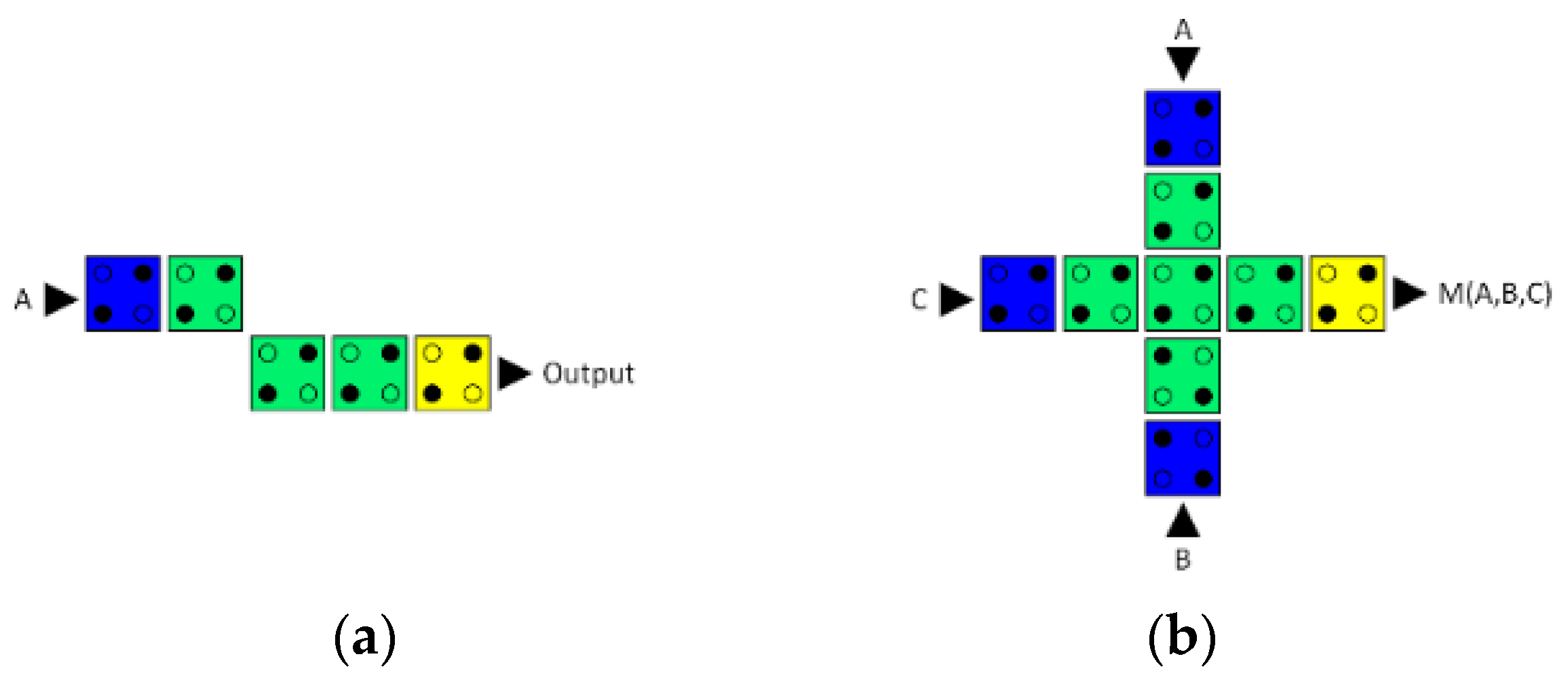
Figure 2.
(a) Logic symbol and (b) QCA layout of the reversible majority gate with three input and three output pins.
Figure 2.
(a) Logic symbol and (b) QCA layout of the reversible majority gate with three input and three output pins.
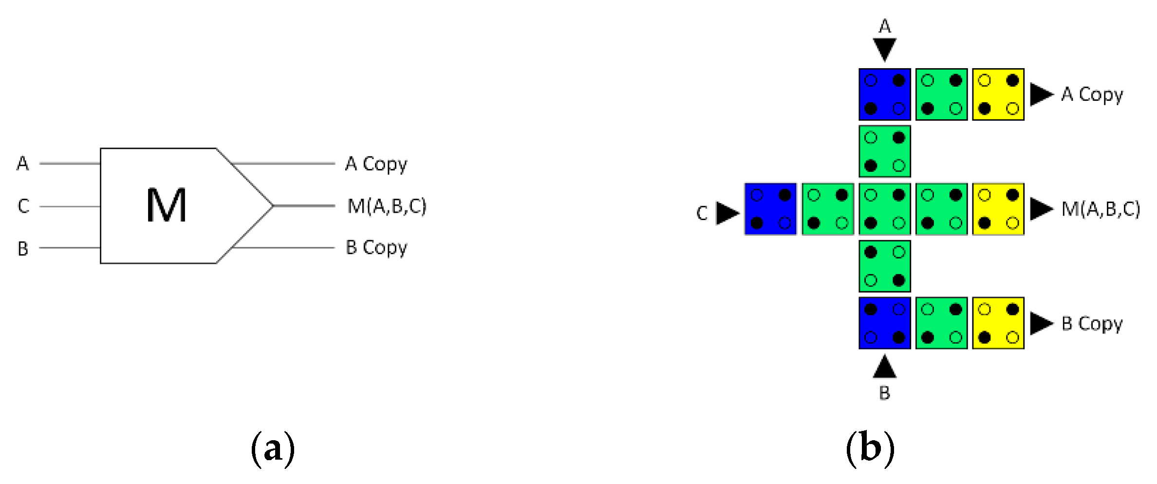
Figure 3.
Partially reversible QCA majority gate: (a) logic symbol diagram and (b) QCA layout.
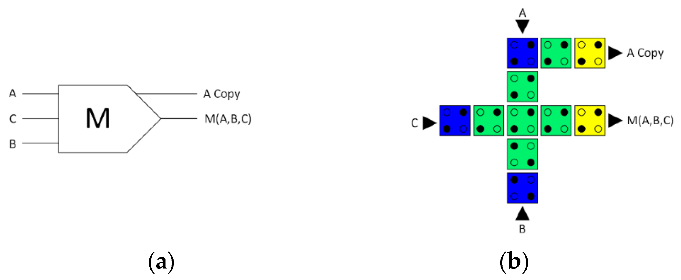
Figure 4.
First hybrid QCA half-adder circuit (a) logic synthesis and (b) QCA layout.
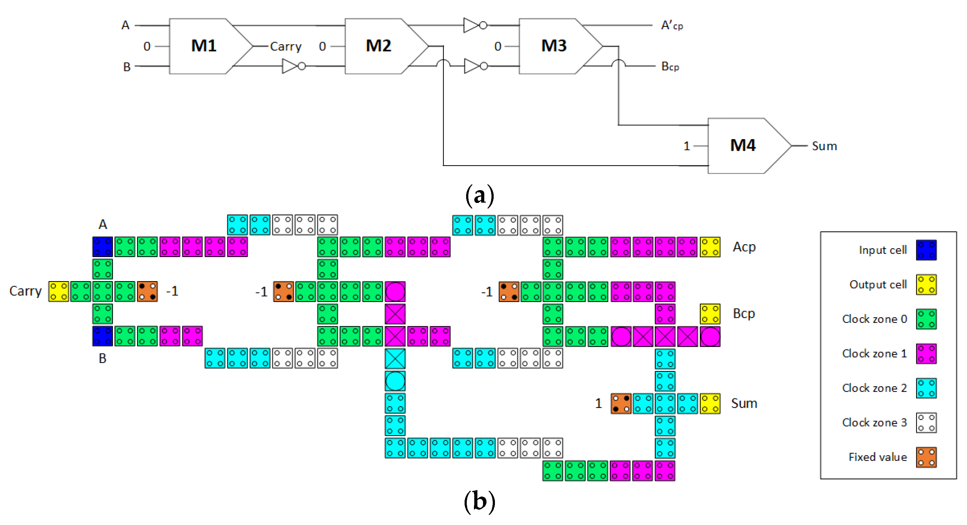
Figure 5.
Second hybrid QCA half-adder circuit (a) logic synthesis and (b) QCA layout.
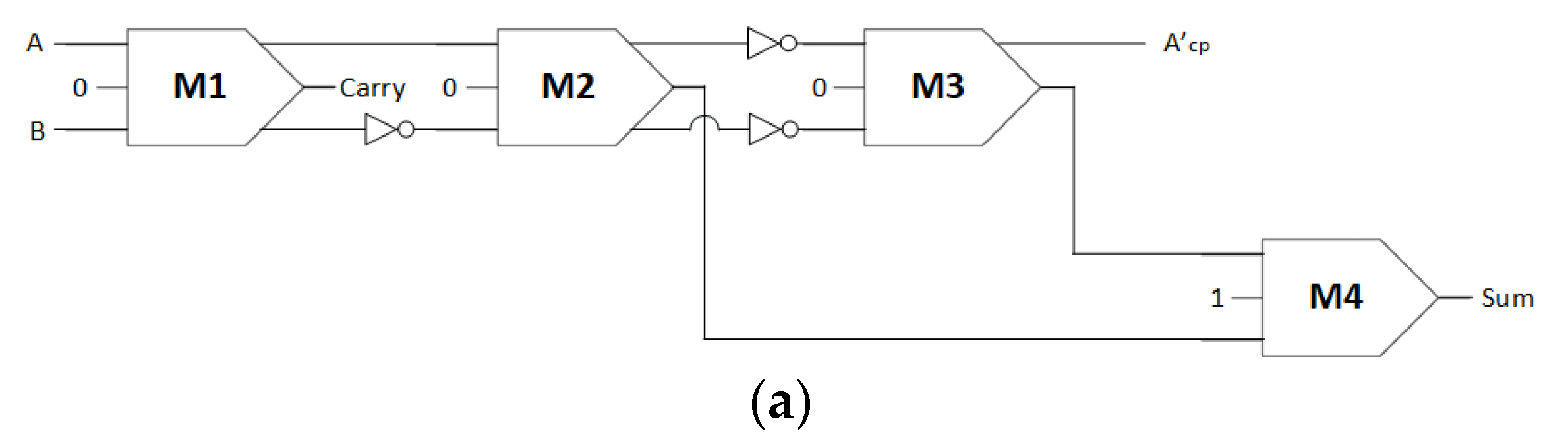
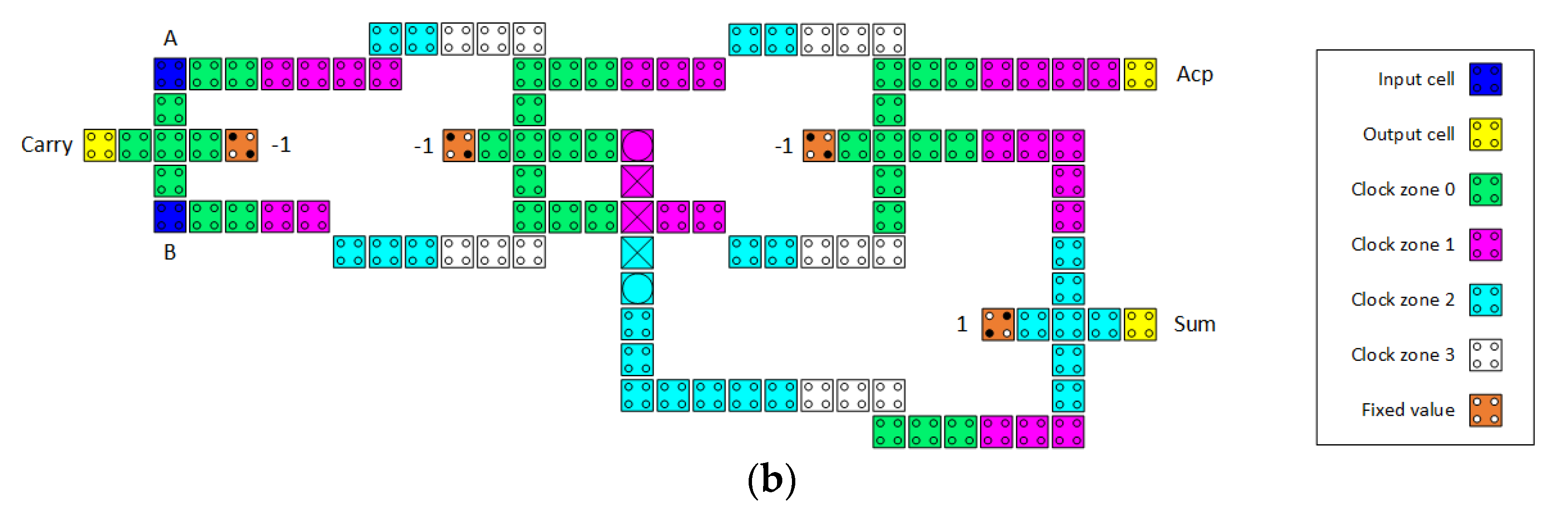
Figure 6.
Third hybrid QCA half-adder circuit (a) logic synthesis and (b) QCA layout.

Figure 7.
Fourth hybrid QCA half-adder circuit (a) logic synthesis and (b) QCA layout.
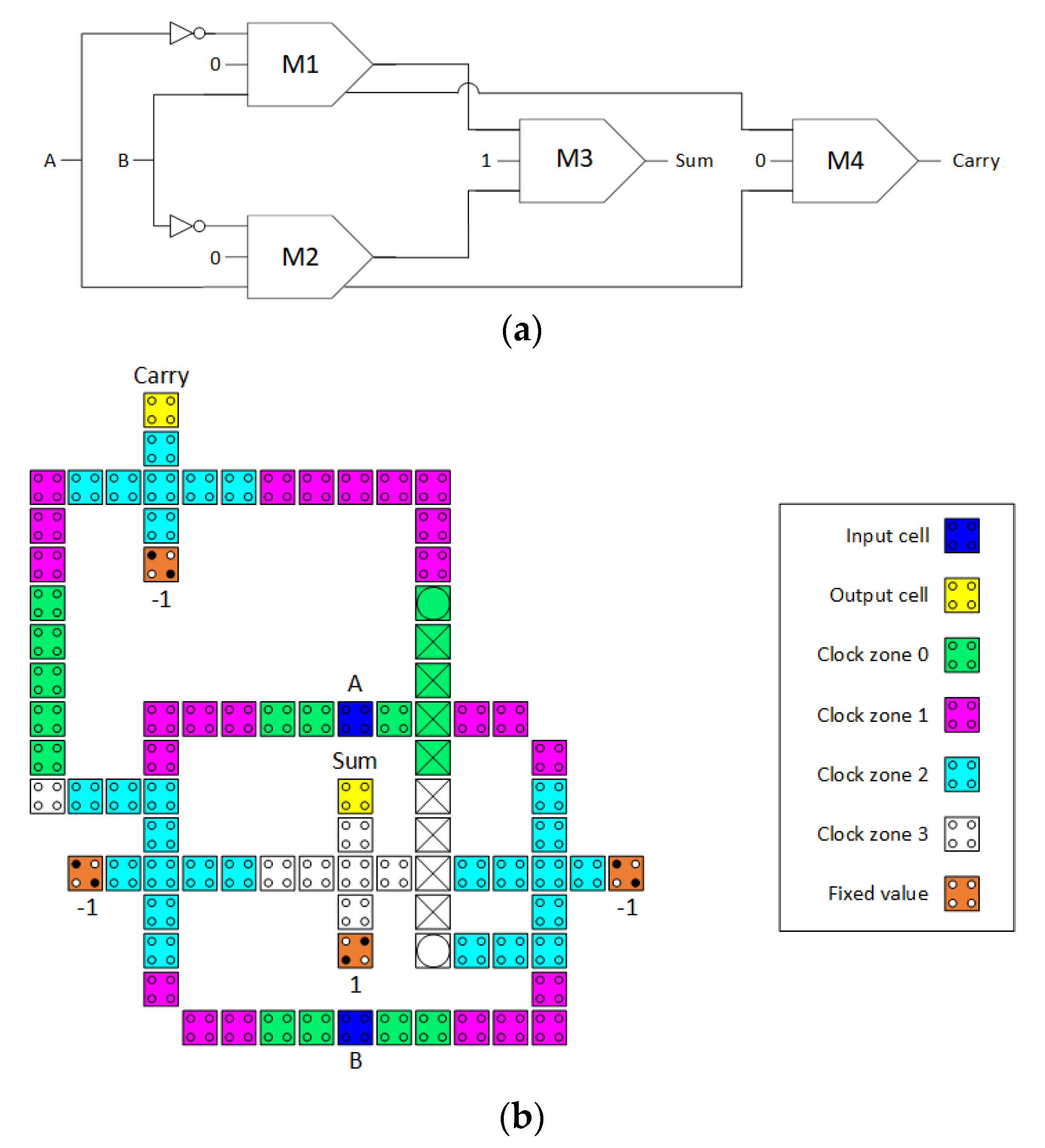
Figure 8.
Simulated waveforms of the first hybrid QCA half-adder design.
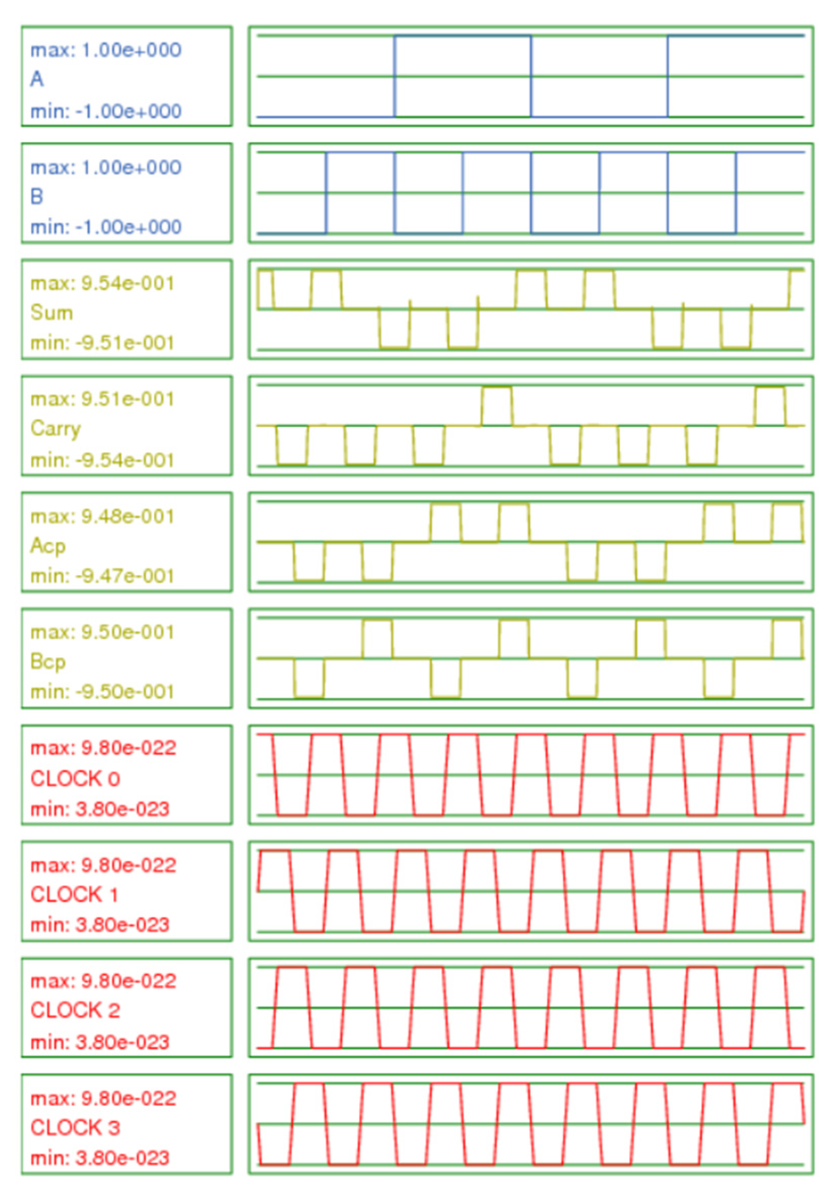
Figure 9.
Simulated waveforms of the second hybrid QCA half-adder design.
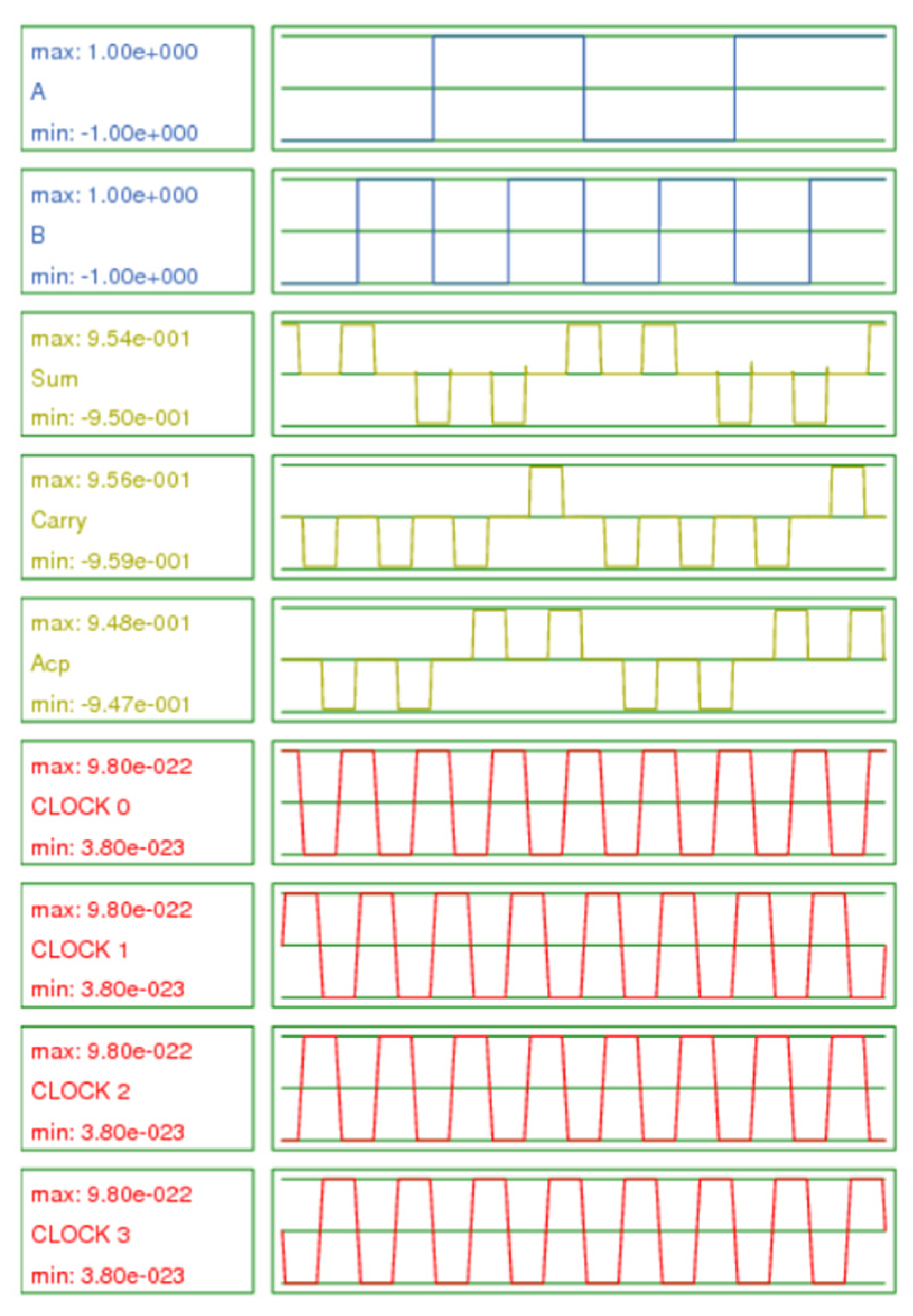
Figure 10.
Simulated waveforms of the third hybrid QCA half-adder design.
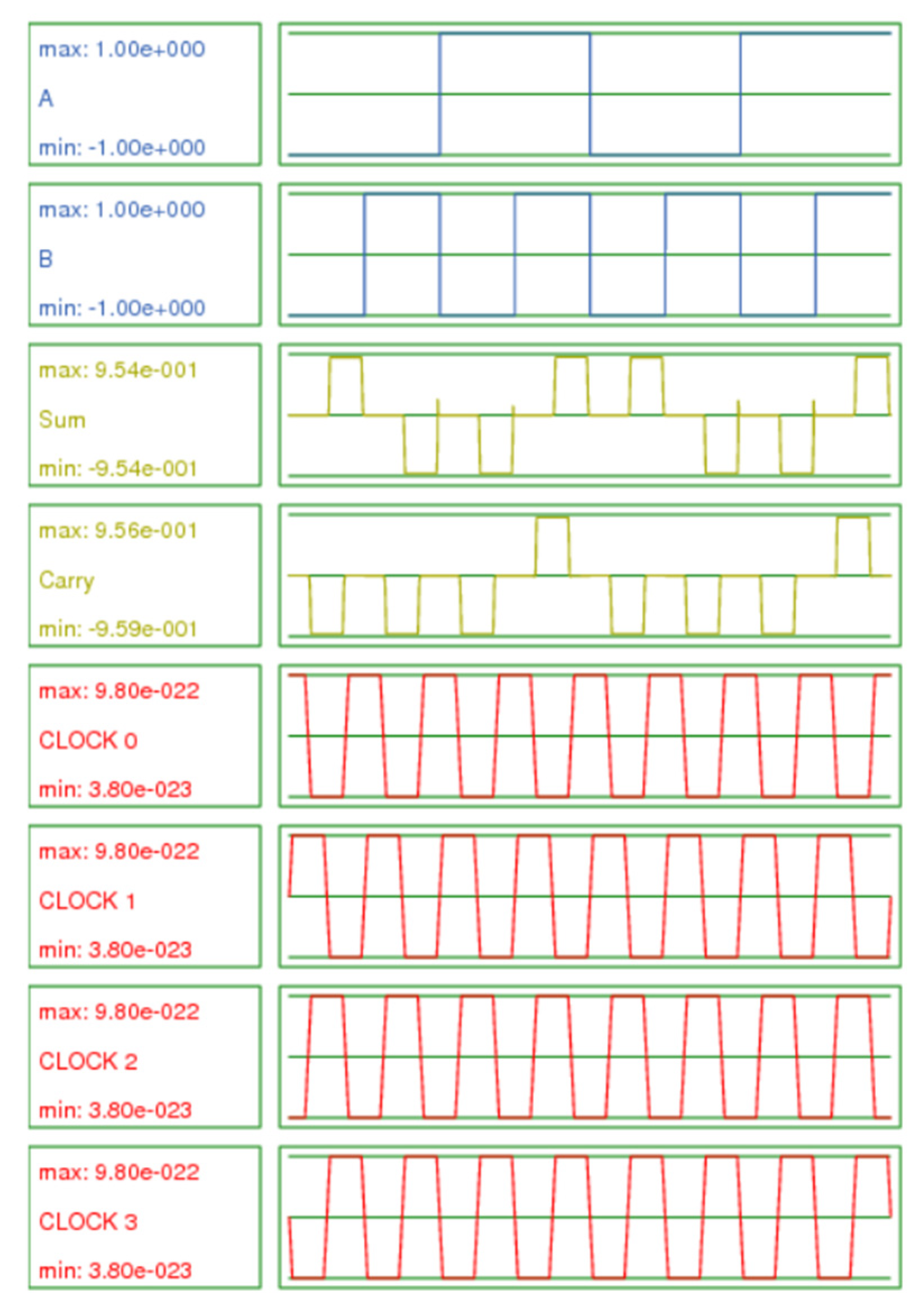
Figure 11.
Simulated waveforms of the fourth hybrid QCA half-adder design.
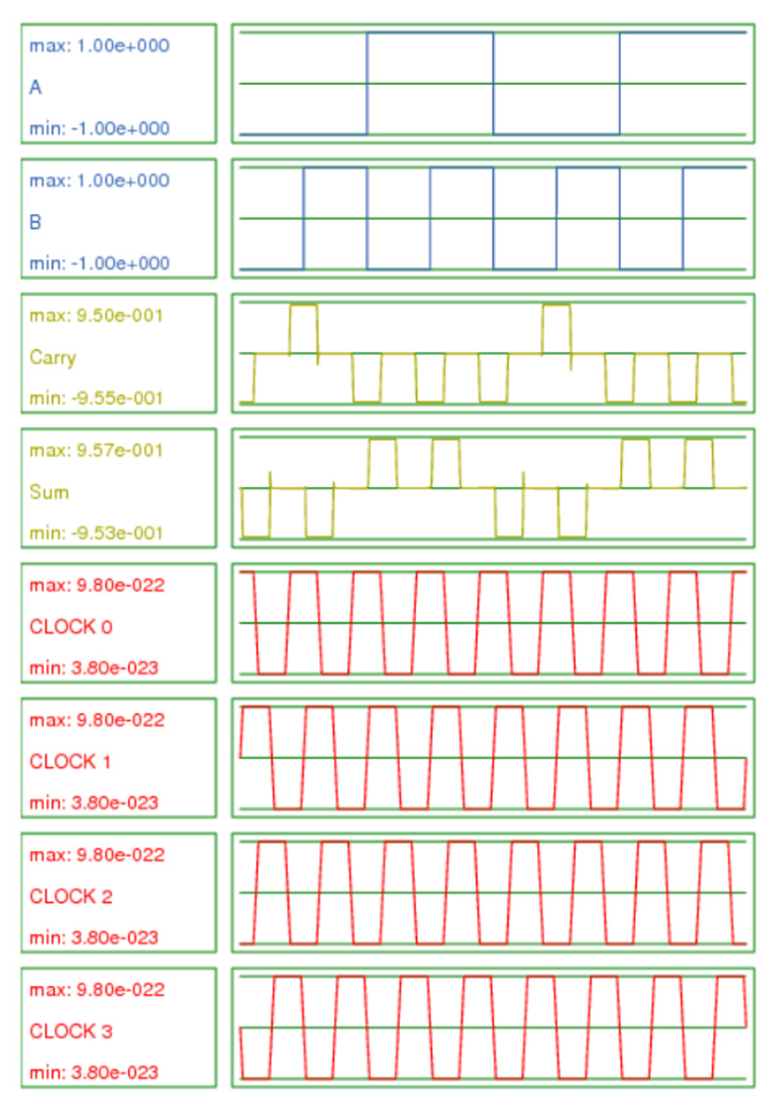
Figure 12.
Average energy dissipation and information loss of the hybrid QCA half-adder circuits (see Table 7 for the gate composition of the 4 designs).
Figure 12.
Average energy dissipation and information loss of the hybrid QCA half-adder circuits (see Table 7 for the gate composition of the 4 designs).
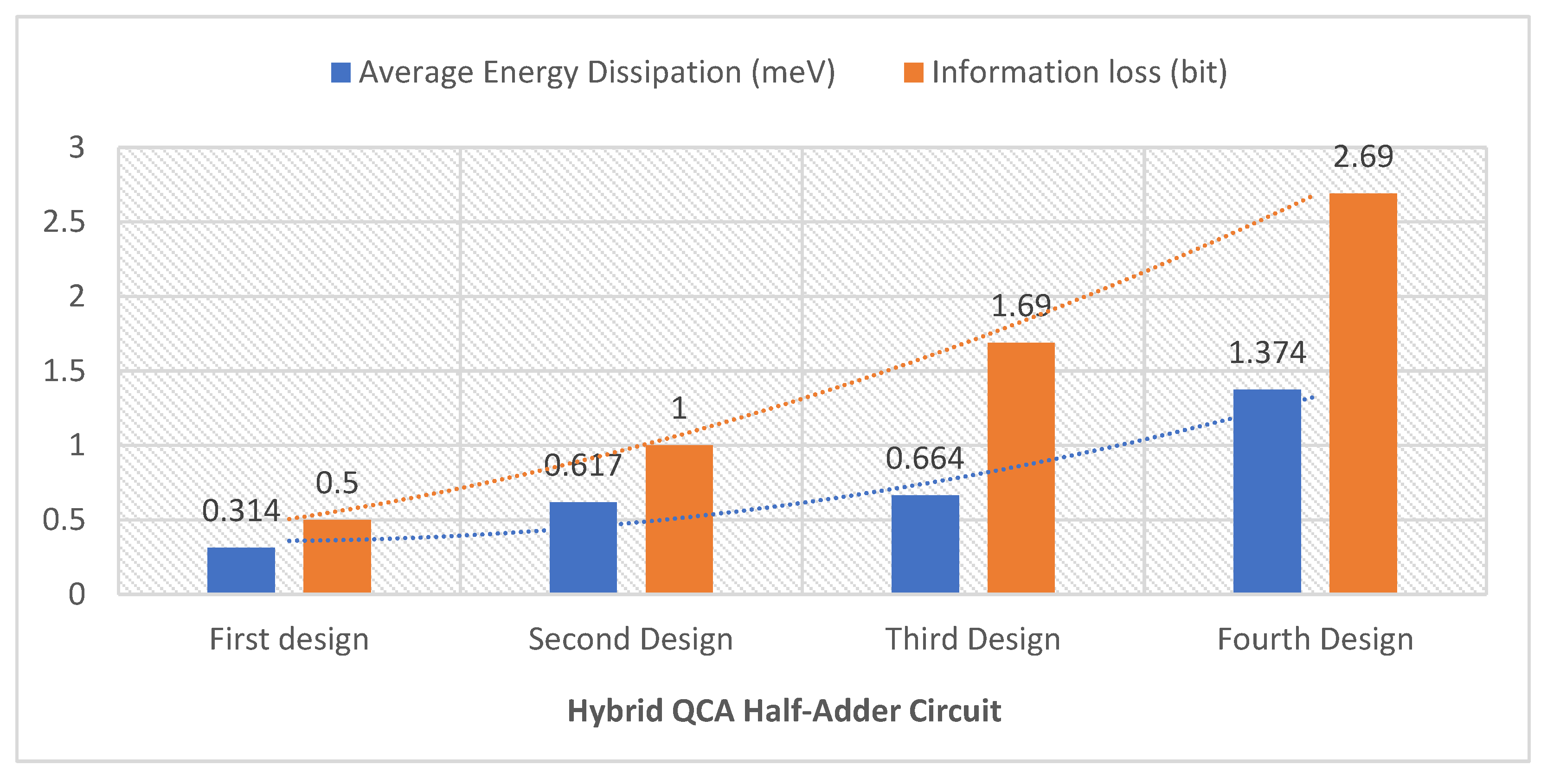
Figure 13.
Cost of the hybrid QCA half-adder circuits.
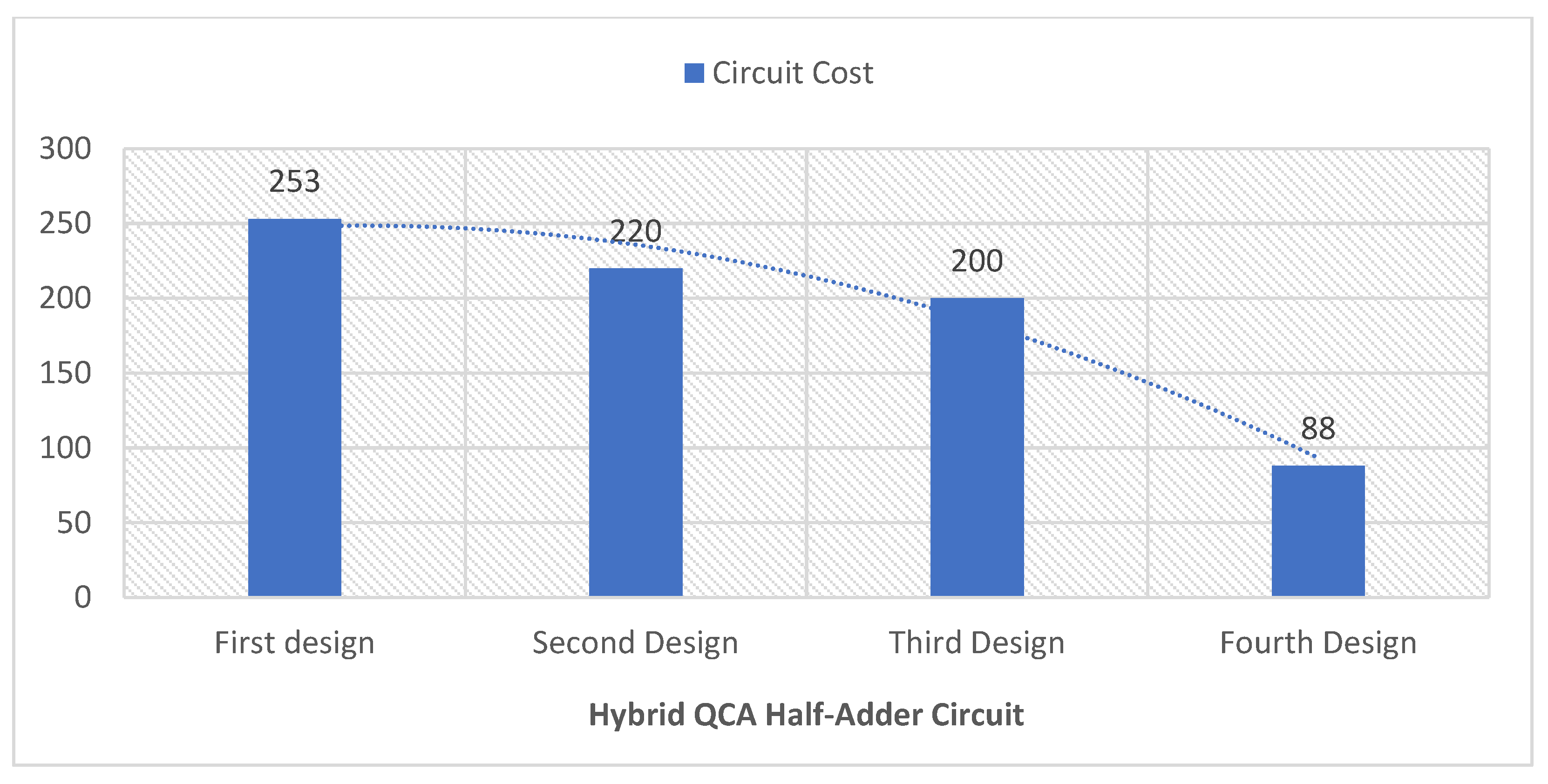

Table 1.
Technological and simulation parameters.
| Parameter | Description | Value |
|---|---|---|
| QD size | Quantum dot size | 5 nm |
| Cell area | Dimensions of each cell | 18×18 nm |
| Cell distance | Distance between two cells | 2 nm |
| Layer separation | Distance between QCA layers in multilayer crossing | 11.5 nm |
| Clock high | Max. saturation energy of the clock signal | 9.8E-22 J |
| Clock low | Min. saturation energy of the clock signal | 3.8E-23 J |
| Relative permittivity | Relative permittivity of the materials used in the QCA systems (GaAs and AlGaAs) | 12.9 |
| Radius of effect | Maximum distance between cells for which interactions are considered | 80 nm |
| Temp | Operating temperature | 1 K |
| τ | Relaxation time | 1E-15 s |
| Tγ | Period of the clock signal | 1E-9 s |
| Tin | Period of the input signals | 1E-9 s |
| Tstep | Time interval of each iteration step | 1E-16 s |
| Tsim | Total simulation time | 8E-9 s |
| γshape | Shape of the clock signal slope | Gaussian |
| γslope | Rise and fall time of the clock signal | 1E-10 s |
Table 2.
Hybrid QCA half-adder circuit truth table.
| A | B | Sum | Carry |
|---|---|---|---|
| 0 | 0 | 0 | 0 |
| 0 | 1 | 1 | 0 |
| 1 | 0 | 1 | 0 |
| 1 | 1 | 0 | 1 |
Table 3.
Information dissipation calculation for the first hybrid QCA half-adder design.
| (a) Gate M1 | |||||||||||||
| Input | Output | ||||||||||||
| 0 | 0 | ¼ | 0.5 | 0 | 0 | 0 | ¼ | 0.5 | |||||
| 0 | 1 | ¼ | 0.5 | 0 | 0 | 1 | ¼ | 0.5 | |||||
| 1 | 0 | ¼ | 0.5 | 0 | 1 | 0 | ¼ | 0.5 | |||||
| 1 | 1 | ¼ | 0.5 | 1 | 1 | 1 | ¼ | 0.5 | |||||
| 2 | 2 | ||||||||||||
| = 0 | |||||||||||||
| (b) Gate M2 | |||||||||||||
| Input | Output | ||||||||||||
| 0 | 1 | ¼ | 0.5 | 0 | 0 | 1 | ¼ | 0.5 | |||||
| 0 | 0 | ¼ | 0.5 | 0 | 0 | 0 | ¼ | 0.5 | |||||
| 1 | 1 | ¼ | 0.5 | 1 | 1 | 1 | ¼ | 0.5 | |||||
| 1 | 0 | ¼ | 0.5 | 0 | 1 | 0 | ¼ | 0.5 | |||||
| 2 | 2 | ||||||||||||
| = 0 | |||||||||||||
| (c) Gate M3 | |||||||||||||
| Input | Output | ||||||||||||
| 1 | 0 | ¼ | 0.5 | 0 | 1 | 0 | ¼ | 0.5 | |||||
| 1 | 1 | ¼ | 0.5 | 1 | 1 | 1 | ¼ | 0.5 | |||||
| 0 | 0 | ¼ | 0.5 | 0 | 0 | 0 | ¼ | 0.5 | |||||
| 0 | 1 | ¼ | 0.5 | 0 | 0 | 1 | ¼ | 0.5 | |||||
| 2 | 2 | ||||||||||||
| = 0 | |||||||||||||
| (d) Gate M4 | |||||||||||||
| Input | Output | ||||||||||||
| 0 | 0 | ½ | 0.5 | 0 | ½ | 0.5 | |||||||
| 0 | 1 | 1 | |||||||||||
| 1 | 0 | ¼ | 0.5 | 1 | ½ | 0.5 | |||||||
| 0 | 0 | ¼ | 0.5 | 0 | |||||||||
| 1.5 | 1 | ||||||||||||
| = 0.5 | |||||||||||||
Table 4.
Information dissipation calculation for the second hybrid QCA half-adder design.
| (a) Gate M1 | ||||||||||
| Input | Output | |||||||||
| 0 | 0 | ¼ | 0.5 | 0 | 0 | 0 | ¼ | 0.5 | ||
| 0 | 1 | ¼ | 0.5 | 0 | 0 | 1 | ¼ | 0.5 | ||
| 1 | 0 | ¼ | 0.5 | 0 | 1 | 0 | ¼ | 0.5 | ||
| 1 | 1 | ¼ | 0.5 | 1 | 1 | 1 | ¼ | 0.5 | ||
| 2 | 2 | |||||||||
| = 0 | ||||||||||
| (b) Gate M2 | ||||||||||
| Input | Output | |||||||||
| 0 | 1 | ¼ | 0.5 | 0 | 0 | 1 | ¼ | 0.5 | ||
| 0 | 0 | ¼ | 0.5 | 0 | 0 | 0 | ¼ | 0.5 | ||
| 1 | 1 | ¼ | 0.5 | 1 | 1 | 1 | ¼ | 0.5 | ||
| 1 | 0 | ¼ | 0.5 | 0 | 1 | 0 | ¼ | 0.5 | ||
| 2 | 2 | |||||||||
| = 0 | ||||||||||
| (c) Gate M3 | ||||||||||
| Input | Output | |||||||||
| 1 | 0 | ¼ | 0.5 | 0 | 1 | ¼ | 0.5 | |||
| 1 | 1 | ¼ | 0.5 | 1 | 1 | ¼ | 0.5 | |||
| 0 | 0 | ¼ | 0.5 | 0 | 0 | ½ | 0.5 | |||
| 0 | 1 | ¼ | 0.5 | 0 | 0 | |||||
| 2 | 1.5 | |||||||||
| = 0.5 | ||||||||||
| (d) Gate M4 | ||||||||||
| Input | Output | |||||||||
| 0 | 0 | ½ | 0.5 | 0 | ½ | 0.5 | ||||
| 0 | 1 | 1 | ||||||||
| 1 | 0 | ¼ | 0.5 | 1 | ½ | 0.5 | ||||
| 0 | 0 | ¼ | 0.5 | 0 | ||||||
| 1.5 | 1 | |||||||||
| = 0.5 | ||||||||||
Table 5.
Information dissipation calculation for the third hybrid QCA half-adder design.
| (a) Gate M1 | ||||||||||
| Input | Output | |||||||||
| 0 | 0 | ¼ | 0.5 | 0 | 0 | 0 | ¼ | 0.5 | ||
| 0 | 1 | ¼ | 0.5 | 0 | 0 | 1 | ¼ | 0.5 | ||
| 1 | 0 | ¼ | 0.5 | 0 | 1 | 0 | ¼ | 0.5 | ||
| 1 | 1 | ¼ | 0.5 | 1 | 1 | 1 | ¼ | 0.5 | ||
| 2 | 2 | |||||||||
| = 0 | ||||||||||
| (b) Gate M2 | ||||||||||
| Input | Output | |||||||||
| 0 | 1 | ¼ | 0.5 | 0 | 0 | 1 | ¼ | 0.5 | ||
| 0 | 0 | ¼ | 0.5 | 0 | 0 | 0 | ¼ | 0.5 | ||
| 1 | 1 | ¼ | 0.5 | 1 | 1 | 1 | ¼ | 0.5 | ||
| 1 | 0 | ¼ | 0.5 | 0 | 1 | 0 | ¼ | 0.5 | ||
| 2 | 2 | |||||||||
| = 0 | ||||||||||
| (c) Gate M3 | ||||||||||
| Input | Output | |||||||||
| 1 | 0 | ¼ | 0.5 | 0 | ¼ | 0.5 | ||||
| 1 | 1 | ¼ | 0.5 | 1 | ¾ | 0.31 | ||||
| 0 | 0 | ¼ | 0.5 | 0 | ||||||
| 0 | 1 | ¼ | 0.5 | 0 | ||||||
| 2 | 0.81 | |||||||||
| = 1.19 | ||||||||||
| (d) Gate M4 | ||||||||||
| Input | Output | |||||||||
| 0 | 0 | ½ | 0.5 | 0 | ½ | 0.5 | ||||
| 0 | 1 | 1 | ||||||||
| 1 | 0 | ¼ | 0.5 | 1 | ½ | 0.5 | ||||
| 0 | 0 | ¼ | 0.5 | 0 | ||||||
| 1.5 | 1 | |||||||||
| = 0.5 | ||||||||||
Table 6.
Information dissipation calculation for the fourth hybrid QCA half-adder design.
| (a) Gate M1 | |||||||||
| Input | Output | ||||||||
| 1 | 0 | ¼ | 0.5 | 0 | 0 | ½ | 0.5 | ||
| 1 | 1 | ¼ | 0.5 | 1 | 1 | ||||
| 0 | 0 | ¼ | 0.5 | 0 | 0 | ¼ | 0.5 | ||
| 0 | 1 | ¼ | 0.5 | 0 | 1 | ¼ | 0.5 | ||
| 2 | 1.5 | ||||||||
| = 0.5 | |||||||||
| (b) Gate M2 | |||||||||
| Input | Output | ||||||||
| 0 | 1 | ¼ | 0.5 | 0 | 1 | ½ | 0.5 | ||
| 0 | 0 | ¼ | 0.5 | 0 | 0 | ||||
| 1 | 1 | ¼ | 0.5 | 1 | 1 | ¼ | 0.5 | ||
| 1 | 0 | ¼ | 0.5 | 0 | 0 | ¼ | 0.5 | ||
| 2 | 1.5 | ||||||||
| = 0.5 | |||||||||
| (c) Gate M3 | |||||||||
| Input | Output | ||||||||
| 0 | 0 | ½ | 0.5 | 0 | ½ | 0.5 | |||
| 1 | 0 | 1 | |||||||
| 0 | 1 | ¼ | 0.5 | 1 | ½ | 0.5 | |||
| 0 | 0 | ¼ | 0.5 | 0 | |||||
| 1.5 | 1 | ||||||||
| = 0.5 | |||||||||
| (d) Gate M4 | |||||||||
| Input | Output | ||||||||
| 0 | 0 | ¼ | 0.5 | 0 | ¾ | 0.31 | |||
| 0 | 1 | ¼ | 0.5 | 0 | |||||
| 1 | 0 | ¼ | 0.5 | 0 | |||||
| 1 | 1 | ¼ | 0.5 | 1 | ¼ | 0.5 | |||
| 2 | 0.81 | ||||||||
| = 1.19 | |||||||||
Table 7.
Information dissipation for the proposed hybrid QCA half-adder designs.
| Proposed Half-Adder Design | Number of Majority Gates Used | Information Loss | ||
|---|---|---|---|---|
| Fully Reversible | Partially Reversible | Irreversible | ||
| First design | 3 | 0 | 1 | 0.5 |
| Second design | 2 | 1 | 1 | 1 |
| Third design | 2 | 0 | 2 | 1.69 |
| Fourth design | 0 | 2 | 2 | 2.69 |
Table 8.
Energy dissipation values for majority gates with different levels of reversibility.
| QCA Majority Gate | Energy Dissipation for an Input Combination Signal [meV] | |||||||
|---|---|---|---|---|---|---|---|---|
| 000 | 001 | 010 | 011 | 100 | 101 | 110 | 111 | |
| Standard irreversible [18] | 0.001 | 0.709 | 0.714 | 0.711 | 0.709 | 0.714 | 0.711 | 0.001 |
| Fully reversible [18] | 0.003 | 0.003 | 0.003 | 0.003 | 0.003 | 0.003 | 0.003 | 0.003 |
| Proposed partially reversible (Figure 3b) | 0.002 | 0.052 | 0.052 | 0.053 | 0.053 | 0.053 | 0.052 | 0.002 |
Table 8.
Energy dissipation values for the proposed hybrid QCA half-adder circuits.
| Proposed Hybrid QCA Half-Adder Design | Energy Dissipation for an Input Combination Signal [meV] | Total Energy Dissipation [meV] |
Average Energy Dissipation [meV] |
|||
|---|---|---|---|---|---|---|
| 00 | 01 | 10 | 11 | |||
| First design | 0.367 | 0.283 | 0.378 | 0.228 | 1.256 | 0.314 |
| Second design | 0.550 | 0.641 | 0.635 | 0.641 | 2.467 | 0.617 |
| Third design | 0.646 | 0.641 | 0.726 | 0.642 | 2.655 | 0.664 |
| Fourth design | 1.470 | 1.310 | 1.250 | 1.466 | 5.496 | 1.374 |
Table 9.
Cost values for the proposed hybrid QCA half-adder circuits.
| QCA Half-Adder Circuit | Number of Majority Gates | Number of Inverters | Number of Cells | Area [µm2] |
Delay [clock cycles] |
Crossover Type | Number of Crossovers | Circuit Cost |
|---|---|---|---|---|---|---|---|---|
| First design | 4 | 3 | 117 | 0.16 | 2.75 | Multilayer | 2 | 253 |
| Second design | 4 | 3 | 110 | 0.16 | 2.75 | Multilayer | 1 | 220 |
| Third design | 4 | 3 | 101 | 0.13 | 2.5 | Multilayer | 1 | 200 |
| Fourth design | 4 | 2 | 90 | 0.12 | 1 | Multilayer | 2 | 88 |
Disclaimer/Publisher’s Note: The statements, opinions and data contained in all publications are solely those of the individual author(s) and contributor(s) and not of MDPI and/or the editor(s). MDPI and/or the editor(s) disclaim responsibility for any injury to people or property resulting from any ideas, methods, instructions or products referred to in the content. |
© 2024 by the authors. Licensee MDPI, Basel, Switzerland. This article is an open access article distributed under the terms and conditions of the Creative Commons Attribution (CC BY) license (http://creativecommons.org/licenses/by/4.0/).
Copyright: This open access article is published under a Creative Commons CC BY 4.0 license, which permit the free download, distribution, and reuse, provided that the author and preprint are cited in any reuse.


