
Submitted:
30 April 2024
Posted:
01 May 2024
You are already at the latest version
Abstract
The article presents a multiphase numerical computational fluid dynamics (CFD) for simulating hydrothermal liquefaction of sewage sludge in a continuous plug-flow reactor. The discrete particle method (DPM) was used to analyze the solid particle interaction in liquid-solid high shear flows to investigated coupling computational fluid dynamics (CFD) and discrete phase model (DPM) method. Increasing solid particles interaction were observed with increasing liquid velocity. The study examined the influence of parameters such as flow rate, temperature and residence time on the efficiency of bio-oil production. Furthermore, the trajectories of the solid particles are affected significantly by the ash flow and the solid particle size, thus the trajectories of particles resembles the streamlines. A parametric study is performed to investigate the effect of slurry flow rate, temperature and external heat transfer coefficient on the biocrude oil productions performance. This simulation data will be used in the future to design and scale up a large-scale HTL reactor.
Keywords:
HTL
; Multiphase flow
; CFD
; Plug-flow reactor
; Biofuels
1. Introduction
Hydrothermal liquefaction (HTL-Hydrothermal Liquefaction) is a thermochemical method of converting wet biomass into biofuel from sewage sludge at a temperature (473-673 K) under pressure (5-20MPa)[1]. As a result of this process, water, organic, gaseous and solid fractions are created. The organic fraction is a viscous, black bio-oil with a calorific value of approximately 28-36 MJ/kg, which can be catalytically upgraded by refining to biofuel used in the transport sector. The resulting water fraction contains a significant amount of dissolved organic substances with a high content of nitrogen and phosphorus, which can be used as a fertilizer in agriculture[2,3]. Most of the works published in the literature over the last few decades regarding the biomass HTL process focus mainly on improving the efficiency of the product obtained from the bioraw material [4,5,6,7,8]. Tubular reactors are characterized by: simple structure, low investment and operating costs, easy technical control of the process and a high degree of mixing with relatively short residence time of the liquid in the apparatus. Optimization of the process conditions, such as temperature, pressure, biomass concentration and reaction time, was carried out by Labanpour and Patel [9,10], while the influence of the type of raw material on the process was carried out by Chen and Ruiz [11,12]. These works on biomass conversion were carried out in small-volume reactors until the optimal product composition was obtained. Designing this type of continuous reactors requires detailed knowledge of flow and heat dynamics, including reaction kinetics. For this reason, computational fluid dynamics (CFD) can be used as a tool to model the hydrothermal liquefaction process and identify important process parameters involved in the production of bio-oil on an industrial scale. Ranganathan and Savithri developed a two-dimensional CFD model combining the HTL kinetic model of a microalgae suspension in a continuous plug flow reactor. The influence of slurry flow rate, inlet temperature and heat source temperature on product performance is discussed. Xiao, Chen et al. [14,15] analyzed the relationship between temperature profiles and the reaction rate of organic components in a tubular reactor using a CFD model. Joshi et al. developed a 3D CFD model to simulate the influence of process parameters on suspension flow and solid particle transport determined by the Prandtl number. However, previous studies mainly focused on predicting the HTL conversion efficiency of microalgae suspension in continuous tubular reactor mode [17]. Recently, few studies have been reported on the HTL process in continuous reactors on a pilot scale.
This article presents a simulation of the HTL process in a three-dimensional reactor using CFD tools. The influence of individual process parameters on the course of the reaction was determined. In this study, an integrated CFD model with HTL process kinetics was proposed to simulate the effects of slurry flow rate, temperature, residence time, and convective heat transfer that affect the yield of the resulting product in a pilot-scale tubular reactor. The results obtained can be practical used to optimize the structure and determine intensive mixing zones in the HTL process
2. Materials and Methods
Three-dimensional Lagrangian-Eulerian multiphase transient model was used to simulate the flow pattern of three-phase gas-liquid-solid flow. Water was considered as continuous phase (primary phase) and sludge were considered as dispersed phase (secondary phase). The present numerical study includes the continuity and momentum conservation equations, which is applied for each phase.
The governing equations of continuity (1) and momentum (2) balance can be written as follows:
where: , ,- it’s a density (kg/m3), viscosity(m2·s−1) and fluid velocity (m/s)
The energy conservation equation is calculated from the formula (3):
where: appropriately and corresponds to the temperature of the suspension under supercritical conditions and the external temperature of the fluid, i - are the specific heat and thermal conductivity of the fluid, respectively , - heat transfer coefficient W/(m²·K), - surface, m2
where: - mass fraction of the k-th component in the phase i , - diffusive flux of the k-th component (kg/m2s), - production of i as a result of a chemical reaction.
In this study, the average mixture diffusion model was used, which was selected for the diffusive stream and was calculated as follows:
where: - mass fraction of the k-th component in the phase i, - diffusive flux of the k-th component (kg/m2s), - production of i as a result of a chemical reaction, - multi-component diffusion coefficient
2.1. Kinetics
A kinetics model to calculated biocrude oil in HTL process from sewage sludge based on reaction pathways was taken from [Hietala DC, Faeth JL, Savage PE,2013 ] presented in Figure 1. Model ten uwzględnia biochemical content of protein, carbohydrates and lipids which content biocrude, gas and aqous phase. Reaction pathways are first ordinary differential equations, which can be assumed follow Arrhenius kinetics, which have been implemented by User-Defined Functions (UDFs) written in C language. Arrhenious parameters for the reaction pathways was presented in Table 1.
2.3. Geometric and Mesh of HTL Reactor
A 3-D geometry model of tube reactor was presented in Figure 2. The details of reactor parameters geometry and physicochemical properties of slurry was presented in Table 2. The analyses employed hexahedral mesh elements embedded thin mesher, where the geometry was mesher in the ICEM code. Suitable numerical grid for accuracy and convergence results was used a different numerical mesh grid refinements, which was investigated to obtain a reasonable computation requirement. The impact of the computational mesh independence test on the simulation results was performed for 0.9-1.8 million mesh elements. For 1.46 million elements, computational independence was achieved. The mesh size has been refined near the geometry faces to improve calculation accuracy in regions of higher process intensity.
2.4. Numerical Simulation
Nonlinear differential equations with distributed parameters were solved by the ANSYS FLUENT solver, based on the FVM-finite volume method. The coupled velocity-pressure equation was solved using the SIMPLEC algorithm. The Peclet number of the microalgae suspension in the flow ranged from 56 to 952. A second-order differential scheme was used to approximate the convective heat transfer "second-order upwind scheme". The lateral walls were modelled using the slip velocity boundary condition. The central difference scheme was used to approximate diffusion terms in the momentum, energy and composition conservation equations. CFD-DPM model has been applied to study the solid particle movement and their tendency to interaction each other in contact surfaces, thus the particle injection region supplements of an exact numerical solution of species concentration distribution and the particle diffusion.The convergence criteria for conservation of momentum, heat and mass were set to a value of 10-6.
3. Results and Discussions
This paper proposes a CFD tube reactor model integrated with HTL kinetics to simulate the HTL process together with convective heat transfer. Figure 2 shows the effect of temperature (Figure 2a) and residence time distribution (Figure 2b) on the biocrude oil yield, the amount of which increases with increasing temperature, while the amount of the aqueous fraction decreases. This is due to the fact that part of the organic fraction dissolved in water is converted into a gaseous product. As the residence time increases, the amount of gas in the HTL process also increases. At a temperature of 670 K, a yield of approximately 38% biocrude oil was obtained, which corresponds to about 3.8 minutes of residence time of the slurry suspension in the reactor.
Figure 2.
Effects of temperature a) and residence time distribution b) on product yield, %.
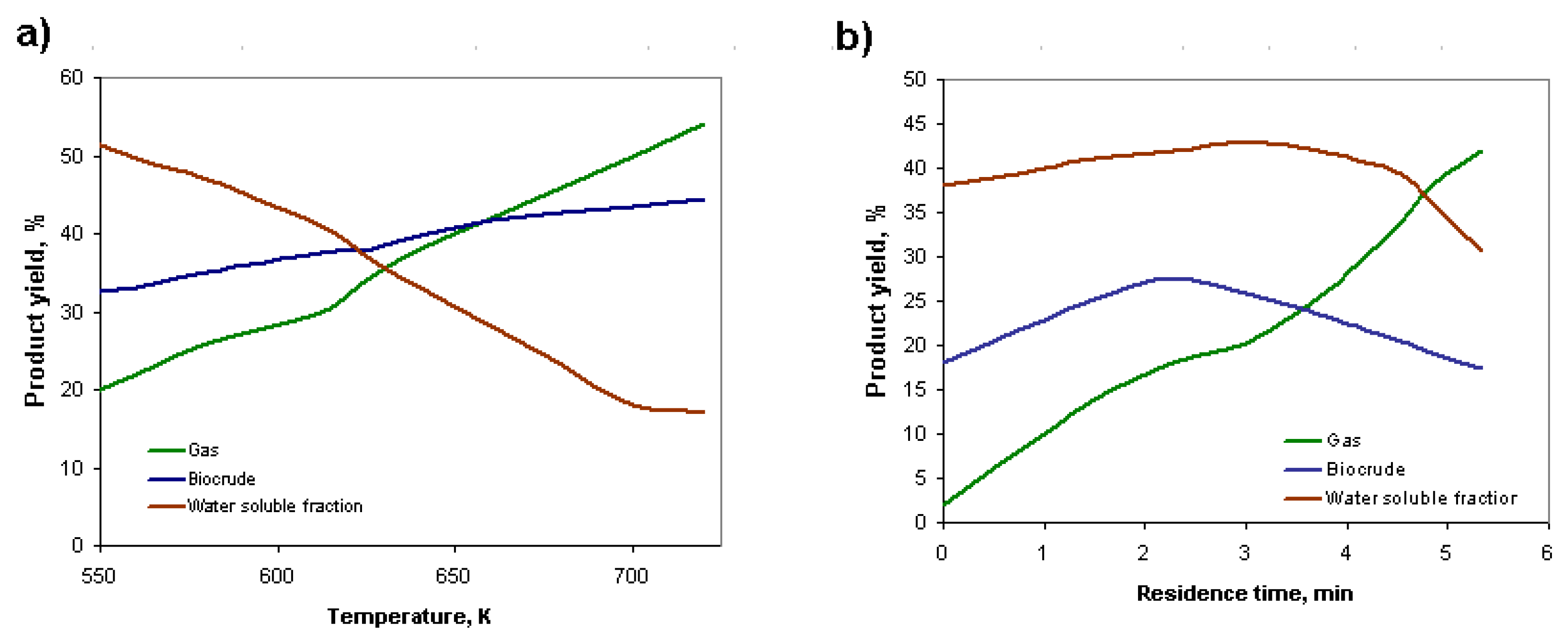
Figure 3.a) and b) show the dynamic nature of the changes in concentration of the individual products formed in the HTL process at 600 K and 400 K. At the higher temperature, a much higher degree of sludge over-reactivity and the amount of gas formed can be seen. At 400 K, for a time of 40 minutes, we had a yield of 27 % of biocrude, where at 600 K the yield was 34 %. At the lower temperature, however, a delay in the nature of the resulting phenomena associated with the thermal decomposition of the raw material, which can be seen, thus temperature significantly affects the decomposition reactions of the organic matter. The dynamics of change in the solid, liquid and gas fractions significantly reflects the rate of change in the composition of the reactants involved in the HTL process. It is worth noting that the distributions of temperature and biocrude oil in HTL reactor is promoted by convective transfer effect, respectively. Implying that temperature is a key factor affected the HTL conversion rate of biomass.
Figure 4 shows the effect of slurry flow rate in the axial direction of reactor temperature. As the flow rate increases, the temperature of the slurry in the flow decreases, which is related to both the heat transfer coefficient and the residence time of the slurry. Figure 4 shows the convective heat transfer coefficient and discharge temperature of the suspended sludge in a simple tube reactor. It can be observed that the convective heat of transfer coefficient of the microalgae suspension increased from 550 to 66 6 W⋅m- 2 ⋅K- 1 with increasing flow rate from 0 to 52 mL/min, while the temperature decreased from 670 to 423 K. In this situation, the conversion rate of the biosolids assisted by the convective heat transfer coefficient of the slurry by increasing the flow rate in a simple tube reactor, results in a lower biomass conversion rate, which is why it is important to ensure a constant temperature throughout the reactor.
Contour plots of slurry flow velocity, temperature, gas mass fraction and biocrude oil are shown in Figure 5. (a). In Figure 5 (a) it can be seen that the maximum slurry velocity occurs in the centre of the tubular reactor in laminar flow. Thus clogging, there are fluctuations in the reactor, because the reactor volume changes and pressure drop appears in the reactor. Pressure fluctuations in the system depends mainly on the reactor volume, solid particle size distribution, as well as the kinematic viscosity and flow rate of the reactor slurry. Therefore, pressure drops can be significantly used to indicate the degree of reactor clogging. An overall high ash content increases the probability of flow clogging in a tubular reactor(>24.1%). Also, the possibility of clogging increases with increasing kinematic viscosity (8.6mm2/s) and solids particle diameter. Therefore, the ash content has a significant impact on the possibility of reactor plugging. Potentially, this problem can be solved by increasing the heating efficiency of the reactor allowing rapid liquefaction of the feedstock; reducing the ash content of the feedstock or increasing the tube diameter. Figure 5b) shows the temperature distribution of the reactor, from which it can be seen that this temperature gradient is mainly due to heat transfer from the reactor wall to the slurry mixture, which has a temperature of about 300 K at the reactor inlet. For the most part, the sludge suspension behaves according to the thermodynamic properties of subcritical water. In Figure 5c) it can be seen an contours plot of gas mass fraction in the external view of the reactor and it’s cross-section. It can be seen that the fluid velocity is lower at the reactor wall and the reactor wall is warmer which accumulates more gas. In Figure 5d) it is presented the biocrude oil concentration, which is irregularly distributed in the middle of the tubular reactor, which is due to hydrodynamic conditions related to mass and heat exchange in the mass flow.
Figure 6 below shows the effect of time and temperature on biocrude yield (a), and the effect of time and sludge flow rate on biocrude yield (b). As the time of the conducted reaction and the temperature increase, the biocrude oil yield increases, with the increase in temperature playing a much greater role than the time of the HTL process. The hydrolysis and dissolution stage of the solids proceeds rapidly and already completely at 330° C after 7 minutes 43.2 % of the solids were dissolved. At temperatures above 500 K over 3 minutes, 58.3 % solids conversion was achieved. At a predicted temperature of 300° C, the gas yield increased from 6.6 wt.% to 20.2 wt.% as the reaction time increased from 1 min to 60 min. Temperature played a more significant role in obtaining a higher gas yield than did the process time. For a given reaction time of 1 min, the gas yield increased from 6.6 wt.% to 65.0 wt.%, and when the temperature increased from 300°C to 600°C. Therefor, the highest increase temperature (600°C and 60 min) and highest gas yield (66.9 wt.%) was obtained. Figure 6 b) shows the effect of flow rate and temperature on the yield of biocrude oil produced. As the flow rate increases, the yield of biocrude oil decreases because the residence time of the slurry in the reactor decreases. There are two opposit inhibiting processes at play here: temperature and flow rate, with flow rate having a much greater role in the decrease in yield of biocrude oil produced.
Figure 7. shown effect of temperature and time on biocrude yield in plug-flow tube HTL reactor. It shows that as the time increases from 15 to 60 minutes, the amount of biocrude oil in the reactor increases from 23% to 42% at a constant flow rate of 6 kg/h. As the reaction progresses, the amount of gaseous phase also increases and the liquid phase shows an increasing trend up to about 52 minutes and shows a decreasing trend after 52 minutes. The yield of biocrude oil also increases with increasing temperature, which is a key factor affecting the rate of biomass conversion in the tubular reactor. In the temperature range150° C to 250 °C, depolymerisation reactions take place. For the 250-350° C temperature range, decomposition reactions predominate, where the decomposition reaction time can be similar to the depolymerisation reaction time, but can be longer for more complex organic compounds.
4. Conclusions
The article presents a 3D multiphysics CFD model of the hydrothermal liquefaction of sewage sludge in a tubular reactor with flow, heat and mass transfer characteristics along chemical reaction. To simulated biocrude oil production in continuous tubular reactor, the temperature and residence time of the process had the greatest impact on the biocrude oil efficiency production. Effect of slurry flow rate, temperature, residence time distribution, external heat transfer coefficient on the HTL products yield was conducted. It is worth noting that residence time and temperature affects on the efficiency of slurry conversion to biooil, which may be important in reactor design. Futhermore, the process will be optimized to minimize energy consumption depending on type of raw material feed and aspects of scale-up to design in industry scale process conduction.
Author Contributions
For research articles with several authors, a short paragraph specifying their individual contributions must be provided. The following statements should be used “Conceptualization, A.W. ; methodology, A.W.; software, A.W.; validation, A.W., ; formal analysis, A.W.; investigation, A.W.; resources, A.W.; data curation, A.W.; writing—original draft preparation, A.W.; writing—review and editing, A.W.; visualization, A.W.; supervision, A.W.; project administration, A.W.; funding acquisition, A.W. All authors have read and agreed to the published version of the manuscript.” Please turn to the CRediT taxonomy for the term explanation. Authorship must be limited to those who have contributed substantially to the work reported.
Funding
This material is based upon work supported by the Ministry of Science and Higher Education, Poland [Grant No. 111610124-323].
Conflicts of Interest
Declare conflicts of interest or state “The authors declare no conflicts of interest.” Authors must identify and declare any personal circumstances or interest that may be perceived as inappropriately influencing the representation or interpretation of reported research results. Any role of the funders in the design of the study; in the collection, analyses or interpretation of data; in the writing of the manuscript; or in the decision to publish the results must be declared in this section. If there is no role, please state “The funders had no role in the design of the study; in the collection, analyses, or interpretation of data; in the writing of the manuscript; or in the decision to publish the results”.
References
- D. Cronin, A.J. Schmidt, J. Billing, T.R. Hart, S.P. Fox, X. Fonoll, J. Norton, M. R. Thorson. D. Cronin, A.J. Schmidt, J. Billing, T.R. Hart, S.P. Fox, X. Fonoll, J. Norton, M. R. Thorson. ACS Sustainable Chemistry & Engineering 2022, 10, 1256–1266. [Google Scholar]
- H. Chen, A.o. Xia, X. Zhu, Y. Huang, X. Zhu, Q. Liao. Hydrothermal hydrolysis of algal biomass for biofuels production: A review. Bioresource Technology 2022, 344, 126213. [Google Scholar] [CrossRef] [PubMed]
- M. Lakshmikandan, A.G. Murugesan, S. Wang, A.-F. Abomohra, P.A. Jovita, S. Kiruthiga. Sustainable biomass production under CO2 conditions and effective wet microalgae lipid extraction for biodiesel production. Journal of Cleaner Production 2020, 247, 119398. [Google Scholar] [CrossRef]
- Gollakota, P.E. Savage. Fast and Isothermal Hydrothermal Liquefaction of Polysaccharide Feedstocks. ACS Sustainable Chemistry & Engineering 2020, 8, 3762–3772. [Google Scholar]
- S. Wang, Y. Mukhambet, S. Esakkimuthu, A.-F. Abomohra. Integrated microalgal biorefinery – Routes, energy, economic and environmental perspectives. Journal of Cleaner Production 2022, 348, 131245. [Google Scholar] [CrossRef]
- K. Viswanathan, S. Wang. Experimental investigation on the application of preheated fish oil ethyl ester as a fuel in diesel engine. Fuel 2021, 285, 119244. [Google Scholar] [CrossRef]
- F. Cheng, Z. Cui, K. Mallick, N. Nirmalakhandan, C.E. Brewer. Brewer, Hydrothermal liquefaction of high- and low-lipid algae: Mass and energy balances. Bioresource Technology 2018, 258, 158–167. [Google Scholar] [CrossRef] [PubMed]
- F. Cheng, J.M. Jarvis, J. Yu, U. Jena, N. Nirmalakhandan, T.M. Schaub, C. E. Brewer, Bio-crude oil from hydrothermal liquefaction of wastewater microalgae. Applied Thermal Engineering 2023, 220, 119725. [Google Scholar]
- A. Lababpour. Continuous Hydrothermal Liquefaction for Biofuel and Biocrude Production from Microalgal Feedstock. ChemBioEng Reviews 2018, 5, 90–103. [Google Scholar] [CrossRef]
- B. Patel, K. Hellgardt. Hydrothermal upgrading of algae paste in a continuous flow reactor. Bioresource Technology 2015, 191, 460–468. [Google Scholar] [CrossRef]
- H. Chen, Q. Liao, Q. Fu, Y. Huang, A. Xia, C. Xiao, X. Zhu. Convective heat transfer characteristics of microalgae slurries in a circular tube flow. International Journal of Heat and Mass Transfer 2019, 137, 823–834. [Google Scholar] [CrossRef]
- H.A. Ruiz, M. Conrad, S.N. Sun, A. Sanchez, G.J.M. Rocha, A. Romani, E. Castro, A. Torres, R.M. Rodriguez-Jasso, L.P. Andrade, I. Smirnova, R.C. Sun, A.S. Meyer. Engineering aspects of hydrothermal pretreatment: From batch to continuous operation, scale-up and pilot reactor under biorefinery concept. Bioresource Technology 2020, 299, 122685. [Google Scholar] [CrossRef] [PubMed]
- P. Ranganathan, S. Savithri. Computational Fluid Dynamics simulation of hydrothermal liquefaction of microalgae in a continuous plug-flow reactor. Bioresource Technology 2018, 258, 151–157. [Google Scholar] [CrossRef]
- Xiao, Q. Liao, Q. Fu, Y. Huang, A. Xia, H. Chen, X. Zhu. Numerical investigation of laminar mixed convection of microalgae slurry flowing in a solar collector. Applied Thermal Engineering 2020, 175, 115366. [Google Scholar] [CrossRef]
- H. Chen, Q. Fu, Q. Liao, C. Xiao, Y. Huang, A. Xia, X. Zhu. Modeling for thermal hydrolysis of microalgae slurry in tubular reactor: microalgae cell migration flow and heat transfer effects. Applied Thermal Engineering 2020, 180, 115784. [Google Scholar] [CrossRef]
- T. Joshi , O. Parkash , and G. Krishan. CFD modeling for slurry flow through a horizontalpipe bend at different Prandtl number. Int. J. Hydrogen Energy 2022, 237, 31–23750. [Google Scholar] [CrossRef]
- L. Qian, J. Ni, Z. Xu, B. Yu, S. Wang, H. Gu, D. Xiang. Biocrude Production from Hydrothermal Liquefaction of Chlorella: Thermodynamic Modelling and Reactor Design. Energies 2021, 14, 6602. [Google Scholar] [CrossRef]
- Valdez, P.J., Tocco, V.J., Savage, P.E. A general kinetic model for the hydrothermal liquefaction of microalgae. Bioresour. Technol. 2014, 163, 123–127. [Google Scholar] [CrossRef] [PubMed]
Figure 1.
Reaction pathways for hydrothermal liquefaction of sewage sludge.
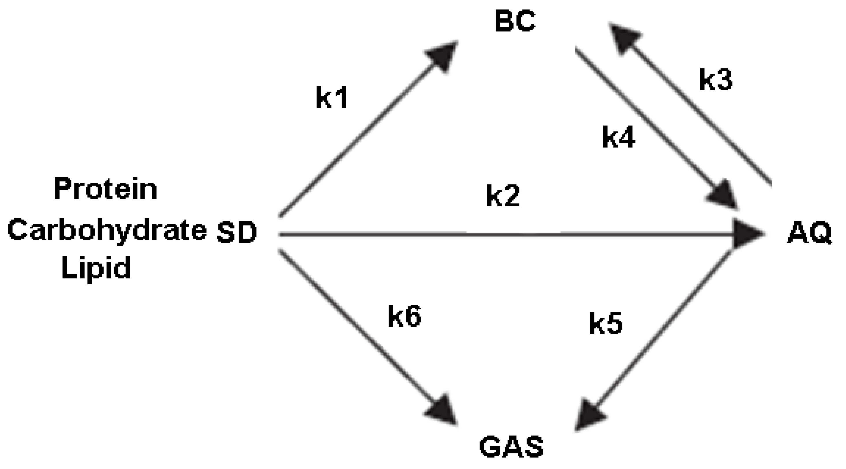
Figure 2.
A 3-D geometry model of tube reactor used to HTL process.
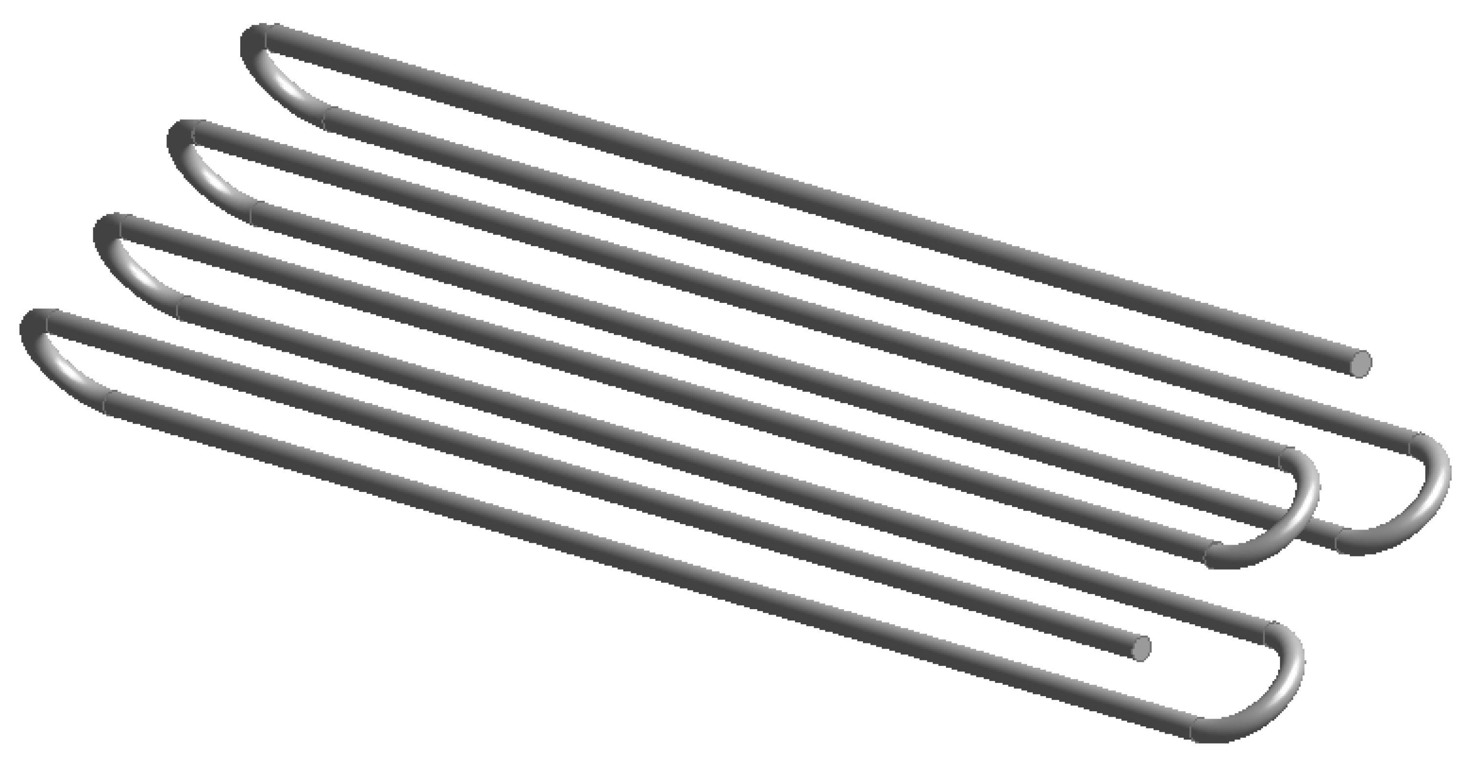
Figure 3.
Effects of temperature for a) 600K b) 400K on biocrude BC, aqua phase AQ, gas and Vt-volatile yield(wt.% ).
Figure 3.
Effects of temperature for a) 600K b) 400K on biocrude BC, aqua phase AQ, gas and Vt-volatile yield(wt.% ).
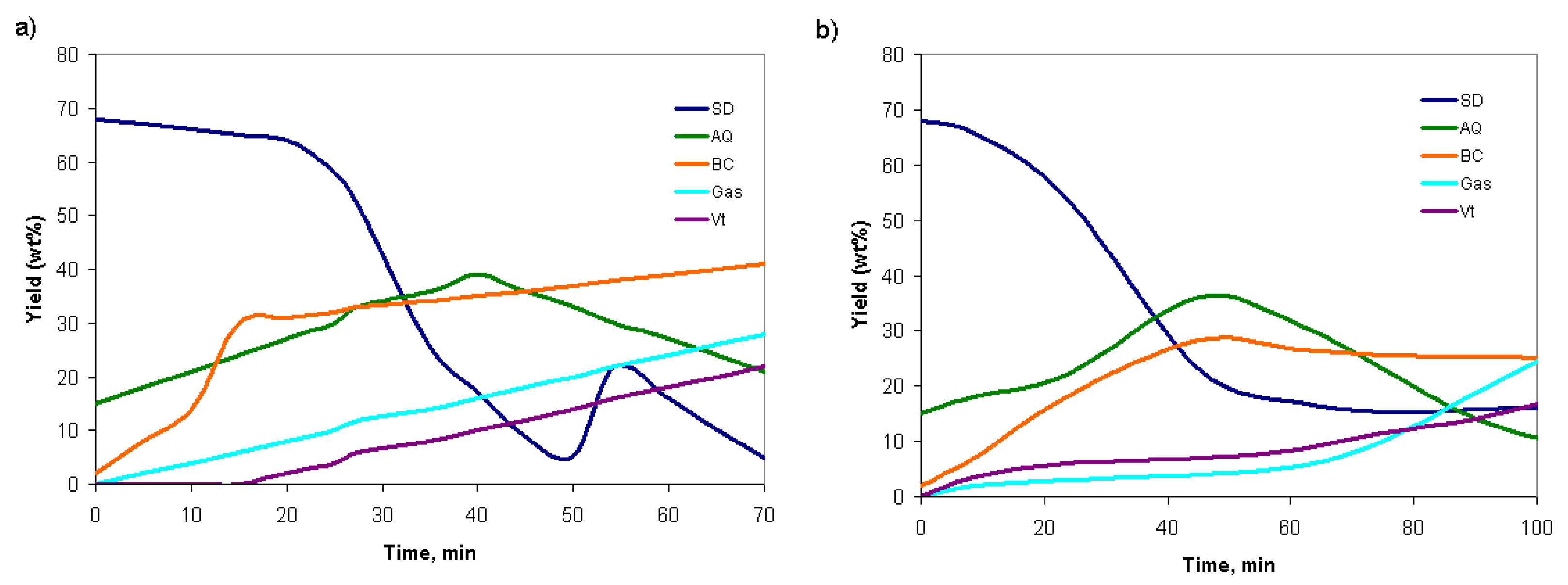
Figure 4.
Effect of slurry flow rate in the axial direction of reactor temperature a) Effect of slurry flow rate in the axial direction on convective heat transfer coefficient and outlet temperature in tubular reactor b).
Figure 4.
Effect of slurry flow rate in the axial direction of reactor temperature a) Effect of slurry flow rate in the axial direction on convective heat transfer coefficient and outlet temperature in tubular reactor b).
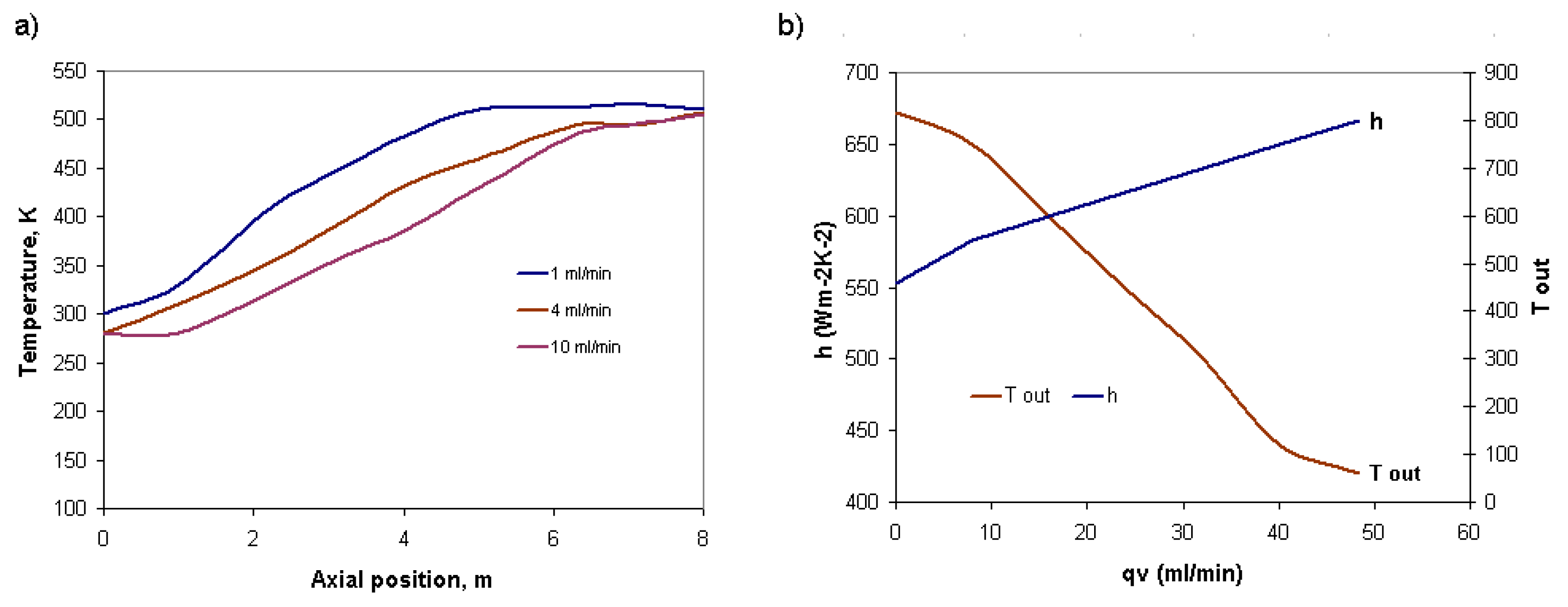
Figure 5.
Contours plot of slurry velocity in the external view of the reactor and in cross-section, m/s a) slurry temperature in the external view of the reactor and in cross-section, K b) biocrude mass fraction in the external view of the reactor and in cross-section c).
Figure 5.
Contours plot of slurry velocity in the external view of the reactor and in cross-section, m/s a) slurry temperature in the external view of the reactor and in cross-section, K b) biocrude mass fraction in the external view of the reactor and in cross-section c).
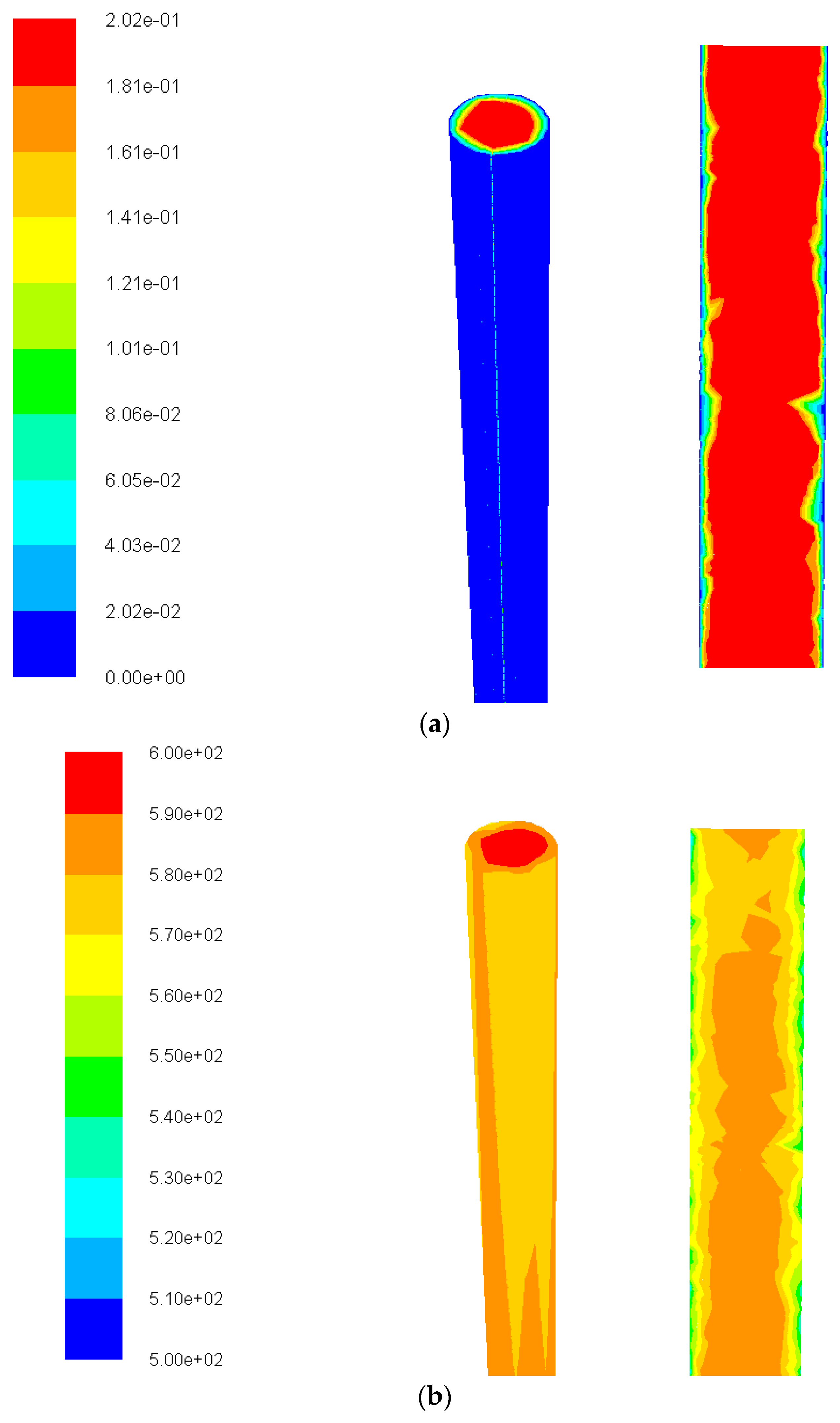
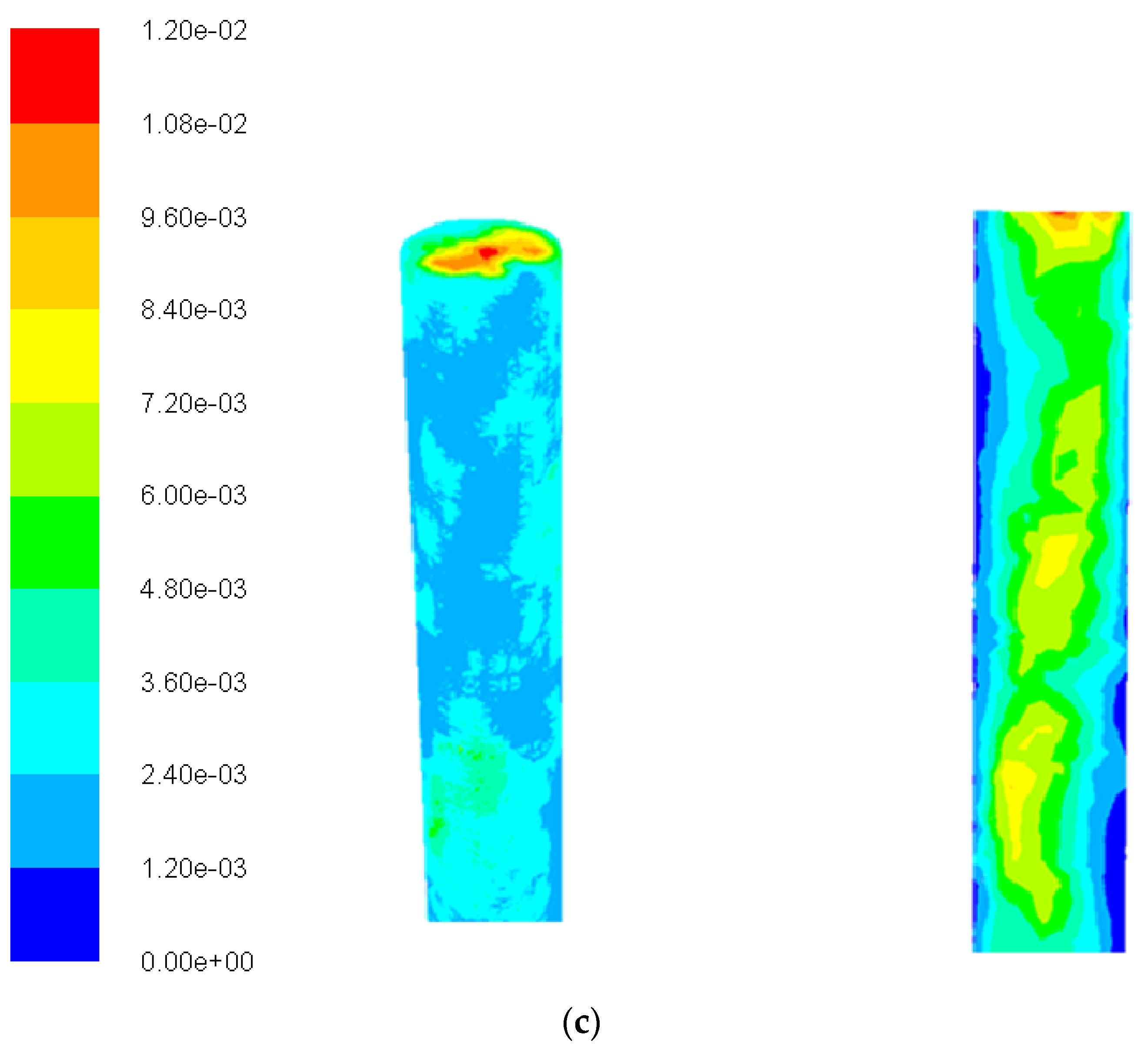
Figure 6.
Effect of time and temperature on biocrude yield a) influence time and flow rate on product yield b).
Figure 6.
Effect of time and temperature on biocrude yield a) influence time and flow rate on product yield b).
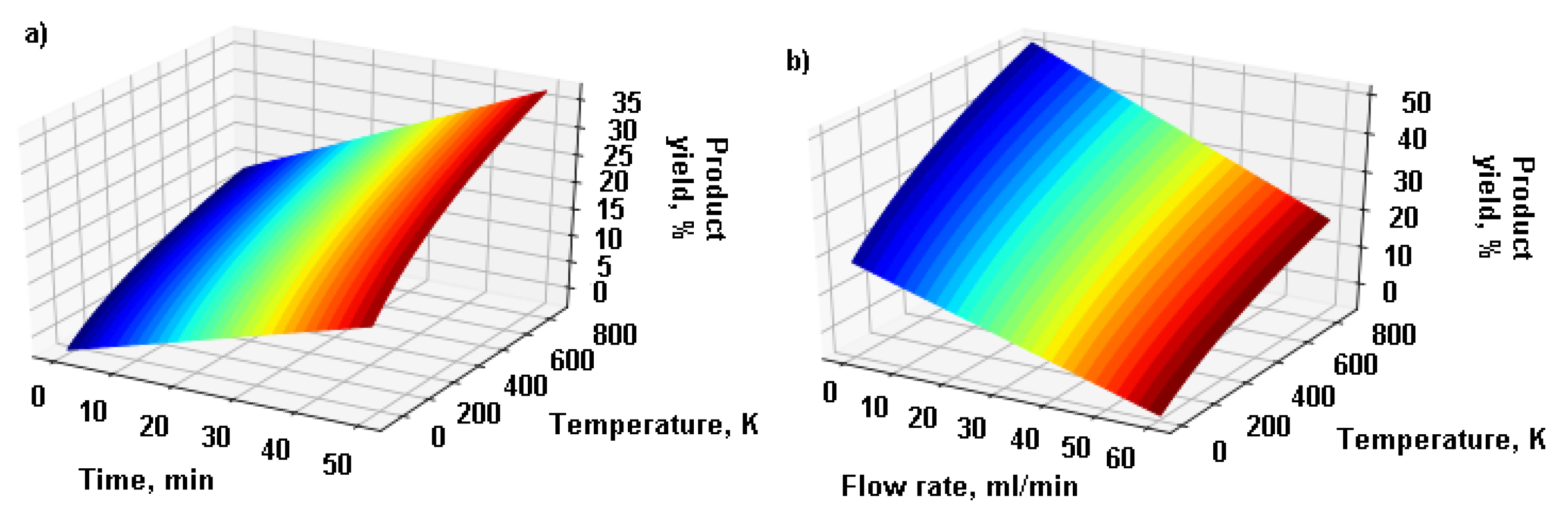
Figure 7.
Effect of temperature and process time on biocrude yield in plug-flow tube HTL reactor.
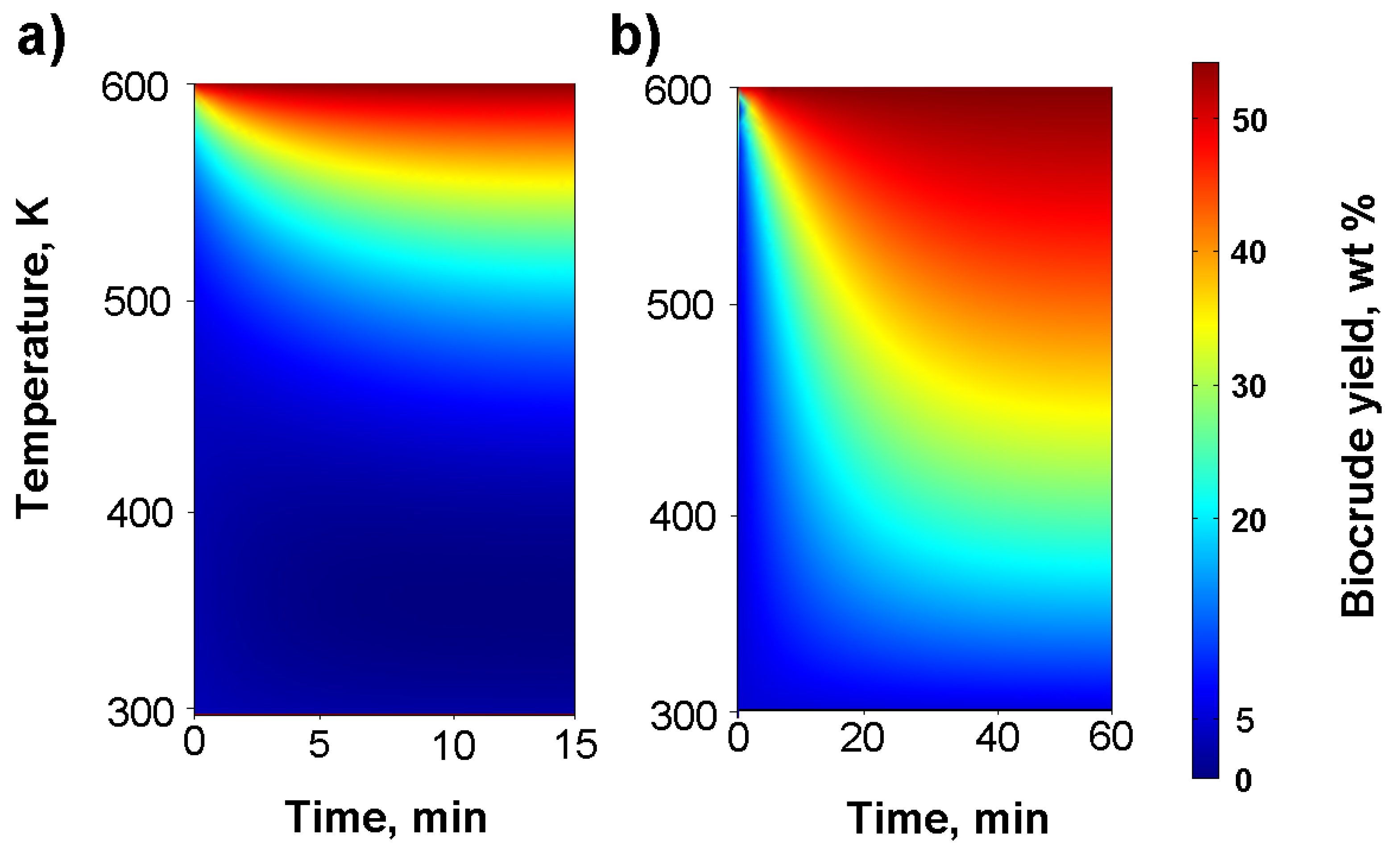

Table 1.
Arrhenius parameters for the reaction rate constans for HTL of sludge.
| Pathway | k ,350℃ (s-1) | Log (A, s-1) | Ea(kJ·mol-1) |
|---|---|---|---|
| SD-BC | 1.1x10⁻² | 3.0±0.8 | 60 |
| SD-AQ | 1.2x10⁻² | 3.6 | 66 |
| SD-GAS | 1.0 x10⁻² | 5.90.3 | 94 |
| BC-AQ | 1.5 x10⁻⁵ | 6.0±1.9 | 129 |
| AQ-VT | 1.9x10⁻³ | 4.8±0.6 | 90 |
| AQ-GAS | 5.4x10⁻⁴ | 5.9 | 110±11 |
Table 2.
Geometric parameters of the HTL reactor for sewage sludge liquefaction.
| Geometrical reactor dimension | |
| Inner diameter, m | 0.008 |
| Outer diameter, m | 0.014 |
| Horizontal distance between Pipes, m | 0.04 |
| Vertical distance between Pipes, m | 0.04 |
| Length of one pipe, m | 0.5 |
| Length of the entire reactor, m | 8 |
| Reactor volume, dm3 | 0.4 |
| Slurry physicochemical properties | |
| Slurry density, kg/m3 | 998.23-1183.4 |
| Slurry viscosity, Pa· S | 0.12-0.23 |
| Flow rate, kg/h | 1- 16 |
Disclaimer/Publisher’s Note: The statements, opinions and data contained in all publications are solely those of the individual author(s) and contributor(s) and not of MDPI and/or the editor(s). MDPI and/or the editor(s) disclaim responsibility for any injury to people or property resulting from any ideas, methods, instructions or products referred to in the content. |
© 2024 by the authors. Licensee MDPI, Basel, Switzerland. This article is an open access article distributed under the terms and conditions of the Creative Commons Attribution (CC BY) license (http://creativecommons.org/licenses/by/4.0/).
Copyright: This open access article is published under a Creative Commons CC BY 4.0 license, which permit the free download, distribution, and reuse, provided that the author and preprint are cited in any reuse.


