Submitted:
03 April 2024
Posted:
04 April 2024
You are already at the latest version
Abstract
In this paper, a 100CMM regenerative thermal oxidizer (RTO) system based on a high heating device for low-emission combustion is implemented at a volatile organic compound (VOCs) gas generation workplace. Existing RTO has a structure that repeats the inflow and discharge of VOCs gas into a cylindrical drum-type rotating disk and has excellent energy efficiency with a heat recovery rate of 95% or more. However, when used for a long time, there is a problem that rotation stops or explodes due to the discharge of pollutants due to dust and thermal expansion due to high temperature of 800℃. To overcome this, a RTO based on a high heating device was developed to reduce low-emission combustion emissions and energy use. Through 177 hours of demonstration time, the oxidation efficiency of VOCs was 98.87%; the waste heat recovery rate was reduced by 95.78%, the fuel consumption was reduced by 21.95%, and the nitrogen oxide concentration was 3.9 ppm
Keywords:
low-emission combustion
; high-heating device
; VOC reduction
; waste heat recovery
; combustion chamber
1. Introduction
Globally, efforts are being made to reduce greenhouse gases and zero carbon due to global warming. The increase in global average temperature in response to climate change is maintained within 2°C compared to pre-industrial times, and in the long run, it is achieving 1.5°C [1].
VOCs gases emitted from paint sprays, packaging film manufacturing, and automobile coating processes that radiate on metal surfaces cause greenhouse gases when discharged directly to the atmosphere. VOCs include aliphatic hydrocarbons, aromatic hydrocarbons, halogen hydrocarbons, ketones, aldehydes, alcohols, glycols, ethers, epoxies, and phenols. Among them, aromatic hydrocarbons such as benzene are strong carcinogens and cause leukemia, central nervous system disorders, and chromosomal abnormalities, and hydrochloride causes ozone layer destruction and global warming. In addition, by producing photochemical oxides through a chain reaction of VOCs, it can cause eye irritation, decreased visibility, and damage to animals, plants, and crops [2]
VOCs reduction technology is divided into diffusion prevention methods, physical methods, chemical methods, and biological methods. Among the chemical methods, the combustion oxidizes and decomposes VOCs at high temperatures, including a direct combustion method (thermal oxidizer), a catalytic oxidizer, and a regenerative thermal oxidizer. Among them, energy costs are consumed with a low heat recovery rate of 95% or more, and technologies that can effectively treat VOCs throughput rate of 95% or more include a heat storage combustion system and a heat storage catalyst combustion system [3].
The heat storage type combustion oxidizer type for the treatment of volatile organic compounds was developed from the (1st and 2nd generation) damper method to the 3rd generation rotary valve method. This rotary valve method has a high VOC removal efficiency of 95%, but as a large installation area is required, process automation and optimized algorithm development are actively in progress, and research is also being conducted on process design and improvement [4].
Recently, strategies to reflect carbon reduction in corporate environmental, social, and governance (ESG) sustainability are spreading worldwide, and as interest from all members of society, including consumers, investors, and governments, increases, it is emerging as a key factor in corporate survival, not choice [5].
In this paper, the energy efficiency is excellent with a heat recovery rate of 95% or more, and a 100 CMM. RTO system based on a high heating device for low-emission combustion is implemented. Existing RTO has a structure that repeats the inflow and outflow of VOCs gas to a rotating disk in the form of a cylindrical drum, and when used for a long time, there is a problem that rotation stops or explodes due to the discharge of pollutants due to dust and thermal expansion due to high temperature of 800℃. To overcome this, we develop a regenerative heat oxidizer based on a high heating element device that reduces low-emission combustion emissions and energy consumption. Through 177 hours of demonstration, the oxidation efficiency of VOCs was 97.87%; the waste heat recovery rate was reduced by 95.78%; the fuel consumption was reduced by 21.95%, and the nitrogen oxide concentration was 3.9 ppm.
2. 100 CMM RTO Implementation Based on High Heating Device
2.1. RTO Modeling and Operating Characteristics
In general, the RTO system is operated through the inflow, burning, and discharge of VOCs gas into the form of a cylindrical drum equipped with a rotating disk and a burner. When a disk drum-type rotating body is used for a long period of time, fine pollutants are generated and the rotation of the disk drum often stops due to thermal expansion by a high temperature of 800°C. In this case, the pollutant gas is not effectively purified, and gas leaks, fires, or explosions occur due to damage to the distributor. It is difficult to repair the rotation failure inside the VOCs inflow and discharge distributor [6]. In particular, in order to minimize friction in the air distribution unit, the air blocking unit in contact with the rotating unit is spaced apart by 2 to 3 mm, and the inflow VOC gas is discharged to the final outlet together with the treated exhaust gas through these gaps, resulting in a phenomenon that the VOC processing efficiency is lowered. Figure 1 shows various accident sites.
In order to solve this problem, it is necessary to design compactly the rotating part and the air blocking part, and which secure a structure and design technology capable of controlling the gas flow while having excellent durability. Figure 2 shows a redesign structure of the system in these problems. Table 1 shows the 100 CMM RTO design specifications.
Figure 3 shows the 100 CMM RTO 3D design based on based on Table 1 standard. In the design drawing, a VOCs gas inlet, a purge gas inlet, a rotating unit, a rail, a rail cover, a chamber for combustion, a structure for supporting a heat storage material, and a processing gas outlet are constituted [7].
The VOC gas transferred from the plant duct is supplied to the gas inlet through the blower, passes through the air distribution plate, and then moves to the ceramic heat storage material layer through the lower chamber. Then, it is supplied to the chamber through the heat storage material, and after combustion and oxidation in the chamber, it passes through the heat storage material located in the opposite direction and is discharged through the lower outlet pipe. Here, the combustion chamber is an iron plate welding structure to perfectly maintain the airtight state of the waste gas, a ceramic block insulation material of 250 mm thickness is installed inside, and each ceramic material for heat exchange is configured in a flange connection structure [8]. The operating temperature of the combustion chamber is 800 to 850℃, and the maximum temperature is designed to operate up to 1,100℃. In the lower body of the combustion chamber, a ceramic heat storage material is stacked to recover 95% of the burned waste heat. Figure 4 shows the plate configuration in the combustion chamber.
Under the ceramic heat storage material, the heat storage material is divided into 12 parts, and the chamber grating is located to support the heat storage material. The purge pipe serves to separate the flow of air introduced from the outside and discharged by the purge fan, and the air supplied to the purge pipe is supplied into the chamber to prevent mixing of the gas flowing into the inlet pipe and the outlet pipe, respectively. At this time, the strongly introduced purge air serves to move the pollutants accumulated in the chamber and the heat storage material to the combustion chamber. The VOCs air distribution plate is divided into an upper plate, an intermediate plate, and a lower plate, which is installed under each chamber to distribute the inlet air and the outlet air. Each of the plates is placed on the paths of the inlet pipe, purge pipe and outlet pipe to separate or control the flow of air.
The intermediate plate is in the form of a flat disk, and the inlet, the purge, and the outlet are sequentially configured from the center. The intermediate plate is connected to the rotation unit and rotates continuously, and the inlet and the outlet are arranged in opposite directions. When the intermediate inlet is opened, the outlet is closed, and the outlet is opened and closed sequentially to prevent mixing of pollutant gas and processing gas. The upper plate and the lower plate are supported by each rail cover set and the intermediate plate is configured to operate in a smooth rotation [6].
2.2. Energy-Saving RTO Design Based on High Heating Element
For normal operation of the RTO combustion chamber, considering that it rises to 920°C during high concentration VOC treatment, the gas burner is designed with a diameter of 125 mm and the outlet is designed with a diameter of 650 mm x 650 mm to discharge high-temperature waste heat. At this time, the combustion chamber heat storage material is calculated to be 250 mm thick with ceramic blocks. Considering the residence time of the processing gas and the thickness of the insulation, the combustion chamber is designed with an Ф of 2,530 mm and a height of 1,875 mm based on the outer diameter. Since the combustion chamber heat storage material may be damaged by thermal shock and fatigue during long-term use, periodic inspection and replacement due to damage are required. In addition, the driving force of the disk rotating plate in the RTO combustion chamber is intensified around the rotating shaft, and untreated gas is discharged to the outlet due to the channeling phenomenon. In order to improve this, the improved rotating plate driving part is improved, and energy reduction efficiency is confirmed through performance check. Figure 6 shows the improved RTO air distributor design and real object.
The VOCs gas combustion function using a burner in the RTO chamber shows the combustion efficiency due to the non-uniform temperature of the combustion chamber. It is deteriorated. If a high heating element is applied for a uniform combustion function, VOCs gas can be uniformly burned inside the combustion chamber. Figure 7 shows the design of the combustion chamber with a high heating element applied.
Figure 8 shows the interior of the combustion chamber with a high heating element applied and the ceramic heat storage material. In the combustion chamber with a high heating element applied, the result of relatively evenly oxidizing VOCs throughout the combustion chamber is derived.
The right design of Figure 8 shows the heat storage agent arrangement design provided on the wall of the combustion chamber. Although the shape of the heat storage material filling part with a cylindrical structure is applied, the ceramic filling arrangement was different from the existing arrangement in order to minimize the unused area and reduce the size of the device by filling the heat storage agent. Through this arrangement design, the device diameter was reduced to Φ2,610 mm ~ Φ2,480 mm, and a total of 60 (5/zone x 12 zones → 60) ceramic fillings were reduced compared to the existing method.
3. Experimental Results
3.1. Simulation of RTO
Figure 10 shows the results of simulating the operation and characteristics of the combustion chamber constructed with a high heating element and a ceramic heat storage agent [7]. The streamline represents the flow of air. At this time, the given pressure, air velocity, and the corresponding VOCs gas concentration are shown. In each figure, the red part represents the larger part and the blue part represents the lower part.
In order to test, the V.O.C gas flowing into the RTO device is approached to the combustion temperature while passing through the preheated ceramic heat storage material layer. The VOC gas that has passed through this layer is burned in the combustion chamber and generates heat at the same time, and at this time, it is oxidized and decomposed at 700 to 800°C with the calorific value. The exhaust gas stores high-temperature waste heat in the ceramic while passing through the heat storage material on the outlet side, and heat storage and heat dissipation are intersected at regular intervals according to the cycle. At this time, the heat recovery efficiency is 95%, the treatment efficiency is oxidized and decomposed by more than 98%, and is discharged as a harmless and odorless clean gas of 60°C. Table 2 is the result of simulating Figure 10.
Figure 12 shows the simulation results of the flow of the combustion chamber according to various air pressures, rates, and gas concentrations. Arrows show the interstitial structure where gas leaks occur.
Figure 13(a) shows the temperature distribution of the combustion chamber to which the burner is applied and the unburned section of the VOCs gas occurs. Here, a jet stream is formed according to the burner flame, and the temperature non-uniformity phenomenon is displayed in a curved shape. In addition, the green in the center of the jet stream indicates the section where VOCs gas is unburned. Figure 13(b) is an analysis of the combustion chamber with a high heating element and a burner applied. It is found that it has a uniform temperature distribution throughout the combustion chamber, and the combustion treatment of VOCs gas is evenly performed.
3.2. Experiment of 100 CMM System Based on High Heating Element and Burner
The final designed and manufactured RTO device experiment is tested from the VOCs gas inlet generated in the coating film production system to the VOC concentration discharged from the distributor. For the validity of the test, it was conducted together with the Korea Testing Laboratory (KTL) which is a national certificate [8]. Figure 12 is the value obtained by measuring the gas concentration discharged from the drying unit (a) and (b) the printing unit of the coating film production system. The concentration generated by the drying unit changed between a maximum of 3,979 ppm and a minimum of 593 ppm, and the average THC was 2,567 ppm. The concentration generated by the printing unit changed between a maximum of 2,170 ppm and a minimum of 686 ppm, and the average THC was 1,260 ppm. Figure 14 shows the VOCs concentration generated in the coating film system.
Figure 15 shows the experimental pilot RTO configuration. The high-heating element-based RTO system consists of a combustion unit, a heat storage agent filling unit, an air distribution unit, a main, purge, burner blower, and a gas burner.
In the air pollution process test method, the facility inlet gas and exhaust gas concentration are simultaneously measured using a total hydrocarbon (THC) analysis method to calculate the VOC reduction rate as shown in the following Equation (1).
Table 3 shows the average value of total hydrocarbons measured at the front and rear ends by injecting nitrogen oxide at a standard oxygen concentration for 30 minutes, and at this time, the VOCs reduction rate is measured.
Table 4 shows the amount of fuel reduction when the RTO device reaches the normal standard by comparing the existing amount of fuel used = 3.487 = 56.413 kWh with a high heating element = the amount of power applied to the heating element filament + the amount of fuel used = 44.032 kWh. The fuel reduction rate is calculated through Equation (2).
Figure 16 shows the temperature characteristics according to the combustion chamber operation of the RTO to which the burner is applied [9]. After reaching 800°C, the combustion chamber operating temperature was cooled to 750°C by operating the on-site exhaust gas transfer blower at 50 Hz, and then the temperature was raised again. After that, when the burner is operated, the combustion chamber temperature deviation is 799-804°C, showing a deviation of about 5°C.
In the combustion chamber equipped with a high heating element and a burner, the temperature deviation is 10℃ in some sections, and the temperature deviation is 3℃ in the overall stable temperature maintenance section, which can reduce the temperature deviation by about 2℃ compared to the result of the burner operation alone. At this time, the ratio of power supplied to the high heating element under normal operating conditions was around 20~35%, and rather energy saving was obtained by intermittently supplying power to maintain a stable temperature. Figure 17 shows the temperature operation results of combustion chamber with the burner and the high heating element.
Comparing Figure 16 and Figure 17, we can be seen that the temperature characteristics of the combustion chamber using a high heating element are evenly displayed, improving the VOCs reduction rate and fuel reduction efficiency.
As a result of testing the VOC calorific value (based on Toluene calorific value) according to the design conditions of Table 1 in the RTO system to which the high heating element is applied, the data shown in Table 5 were obtained [10,11].
At this time, the combustion energy was 117,578 kcal/hr, hot by pass leak 11,758 kcal/hr, and the fuel consumption was 80,450 kcal/hr, which generated surplus heat. The passing temperature of the heat storage material was 735°C, which was a relatively stable temperature, and the recovery heat was 1,911,341 kcal/hr. The pressure loss occurred 250 to 253 mmAq due to the expansion and reduction of the heat storage material, stack, rotary, and other expansion. Therefore, if the VOCs reduction rate of the RTO system is calculated according to Equation (1), the VOCs removal rate of the burner-type RTO system was 95%, but the RTO system based on the high heating element obtained 97.87%.
4. Conclusions
A 100 CMM (Regenerative Thermal Oxidation) device equipped with a high heating element and a burner was implemented for low-emission combustion at the VOCs-generating workplace. Temperature stability and combustion performance for RTO operation were improved by implementing a combustion chamber design applying a high heating element and a burner at the same time. In particular, the safety of the disk operation in the combustion chamber was achieved through the thermal energy accumulated in the heat storage material and the redesign of the improved RTO distributor. In addition, in the plate fastened to the lower part of the combustion chamber, the sagging phenomenon was prevented by maintaining the plate gap between the upper and lower parts as a repulsive force, and the lifespan was increased by improving to reduce the wear and tear of the parts. This also serves to minimize the wear and fatigue of the system in the driving of the combustion chamber.
The safe operation of the combustion chamber equipped with a high heating element and a burner at the same time resulted in fine dust reduction, VOCs gas emission concentration reduction, and waste heat recovery rate improvement. The combustion energy was 117,578 kcal/hr, hot by pass leak 11,758 kcal/hr, and the fuel consumption was 80,450 kcal/hr, which generated surplus heat. The passing temperature of the heat storage material was 735°C, which was a relatively stable temperature, and the recovery heat was 1,911,341 kcal/hr. Pressure loss occurred 250~253 mmAq due to the reduction of heat storage materials, stacks, rotaries and other expansion. Therefore, the removal ra te of VOCs of the burner-type RTO system was 95%, but the RTO system based on high heating element obtained 97.87%. The waste heat recovery rate using heat storage was 95.78%, and the reduction in fuel use was 21.95%. The concentration of nitrogen oxide discharged during operation was 3.9 ppm.
Until now, the performance has been evaluated by measuring the concentration of volatile organic compound (VOC) exhaust gas according to the operating conditions of the production process and analyzing the change in THC concentration. Economic feasibility was confirmed by conducting simulation and empirical tests.
The part to be studied further in the future will be put to practical use by conducting research on the heat exchange part with the design of a phase conversion material filling column, and by applying the learning effect of artificial intelligence, big data over a long period of time will be built.
Acknowledgments
This work was supported by Ministry of Trade, Industry and Energy Republic of Korea grant funded by the Korea Evaluation institute of Industrial Technology (Project No. 20017234).
References
- J. H. Yoon, Transboundary Air Pollution and Global Governance: Singapore's Network Strategy to Tackle the Indonesian Haze, Korean Society for Regional Studies, Republic of Korea, Vol.34, No.1, 5179, Jan. 2016. https://www.dbpia.co.kr/Journal/articleDetail?nodeId=NODE08788063.
- H.J. Lee; M.H. Chao; D. R. Ko; etc, Causative Substance and Time of Mortality Presented to Emergency Department Following Acute Poisoning: 2014-2018 National Emergency Department Information System, Journal of The Korean Society of Clinical Toxicology, Vol.19 Issue 2, 65-71, Dec.2021. https://koreascience.kr/article/JAKO20210985834.
- H. M. Park; D. H. Yoon; H. M. Jeung; D. H. Jeon, Development of porous plate scrubbers and simulation of IPA treatment efficiency to improve dust collection and deodorization, Safety and Culture Research, Republic of Korea, Vol.13 No.1, 339-349, July 2021. www.fpss.jams.re.kr.
- B.-S. Choi; J. Yi, Simulation and optimization on the regenerative thermal oxidation of volatile organic compounds, Elsevier, Chemical Engineering Journal, Vol.76, Issue 2, 103-114, Feb. 2000. [CrossRef]
- www.k-esg.or.kr/sub, Ministry of Trade, Industry and Energy, Republic of Korea.
- D.H. Jeon; S.W. Jeng, Pre-treatment Method of Irregular Process Emissions for High-Efficiency Combustion Treatment of Volatile Organic Compounds, Autumn Conference of the Korea Gas Association, Republic of Korea, 2021.
- L. Giuntini; A. Bertei; S. Tortorelli; etc, Coupled CFD and 1-D dynamic modeling for the analysis of industrial Regenerative Thermal Oxidizers, Chemical Engineering and Processing-Process Intensification, Vol.157, Aug. 2020. [CrossRef]
- www.ktl.re.kr, Korea Testing Laboratory (KTL), Republic of Korea.
- D.H. Yoon; B.S. Han; T.Y. Lim; E.C. Yang; etc, Implementation of 100CMM Thermal Storage Combustion Oxidizer for VOCs Reduction, 2022 International Conference on Control, Automation and Systems (2022 ICCAS), 1-25. https://ieeexplore.ieee.org/xpl/conhome/10003266/proceeding.
- D.H. Yoon; H.M. Park; D.H. Jeon; H.K. Min, Nitrogen Oxide Reduction Type Regenerative Thermal Oxidation System and Nitrogen Oxide Reduction Method Thereof, United States Patent Application Publication, No: US 2023/0228205 A1, Jul. 20, 2023.
- D.H. Yoon; H.M. Park; D.H. Jeon; H.K. Min, Multistage Variable Type Waste Heat Storage and Recovery Apparatus and Method Thereof, United States Patent Application Publication, No: US 2023/0228500 A1, Jul. 20, 2023.
Figure 1.
Various RTO accident sites.
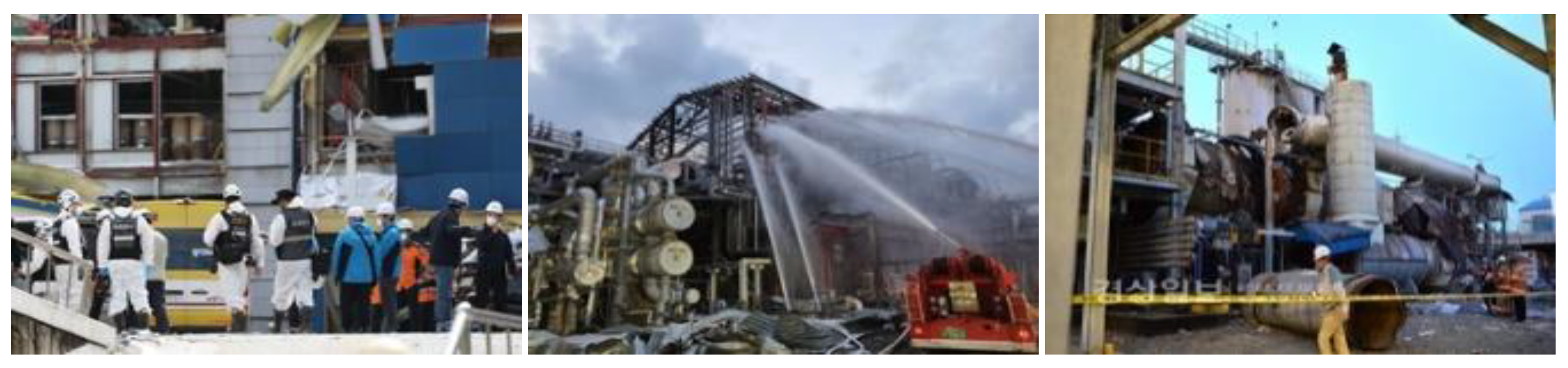
Figure 2.
Redesigned structure.
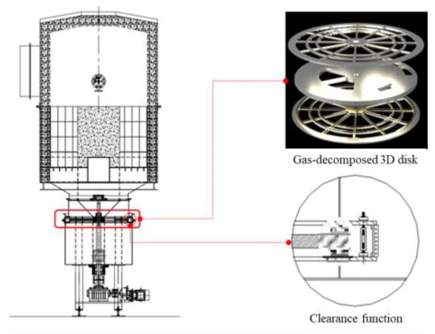
Figure 3.
100 CMM RTO 3D Model.
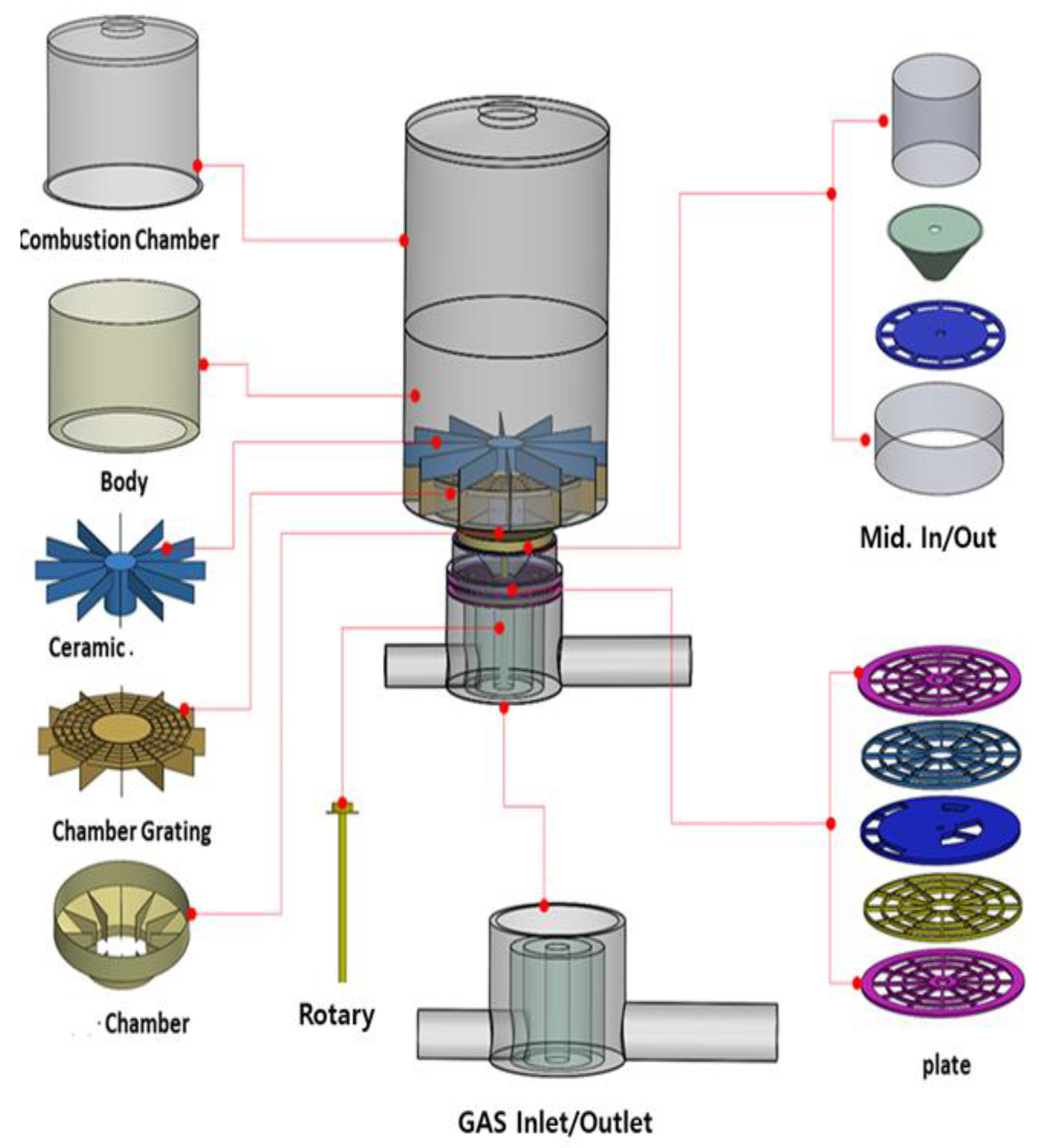
Figure 4.
Plate configuration in the combustion chamber.
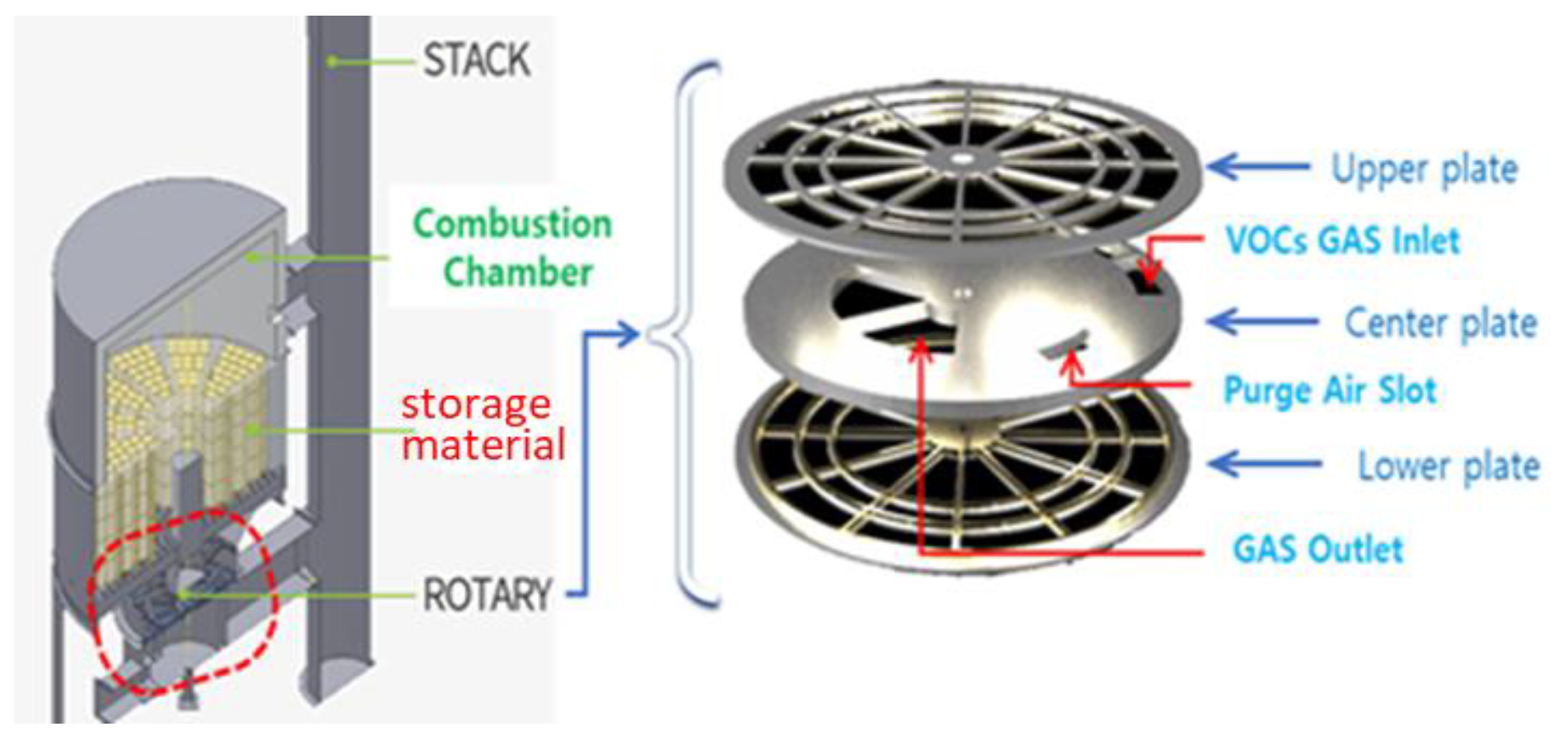
Figure 6.
Improved RTO air distributor design and real object.
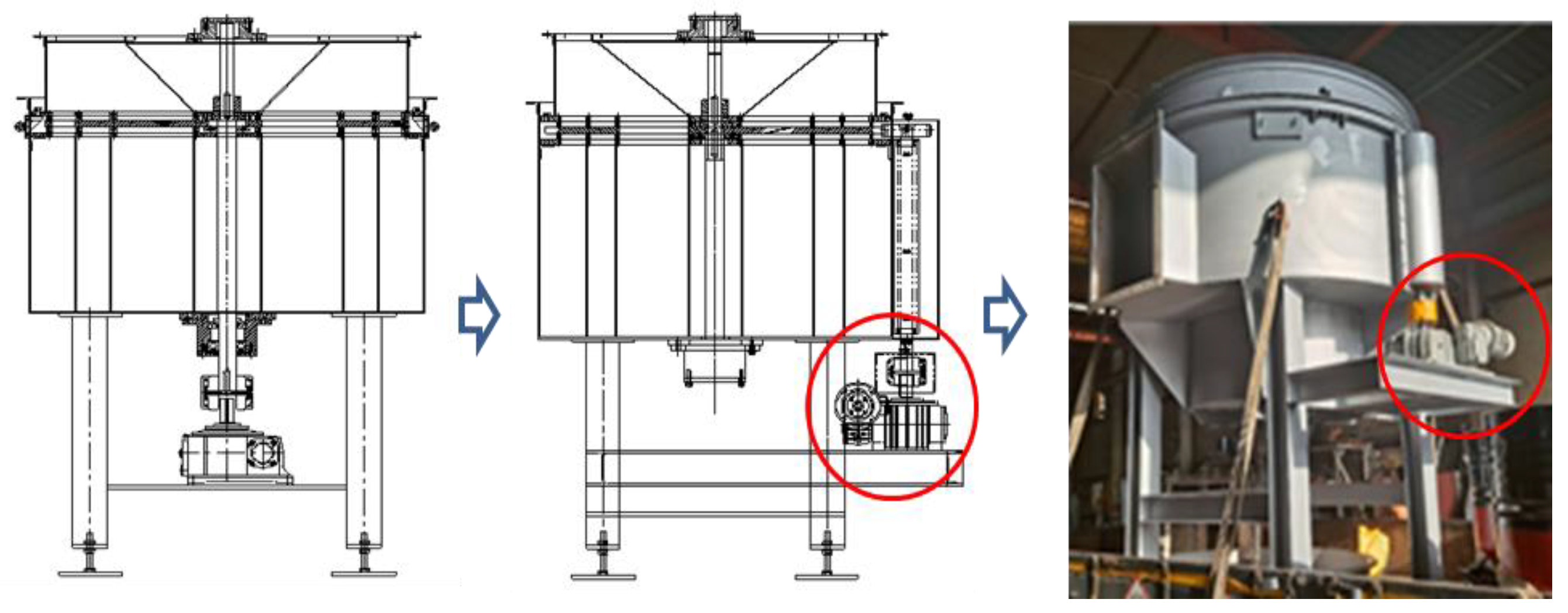
Figure 7.
Design of the combustion chamber with a high heating element applied.
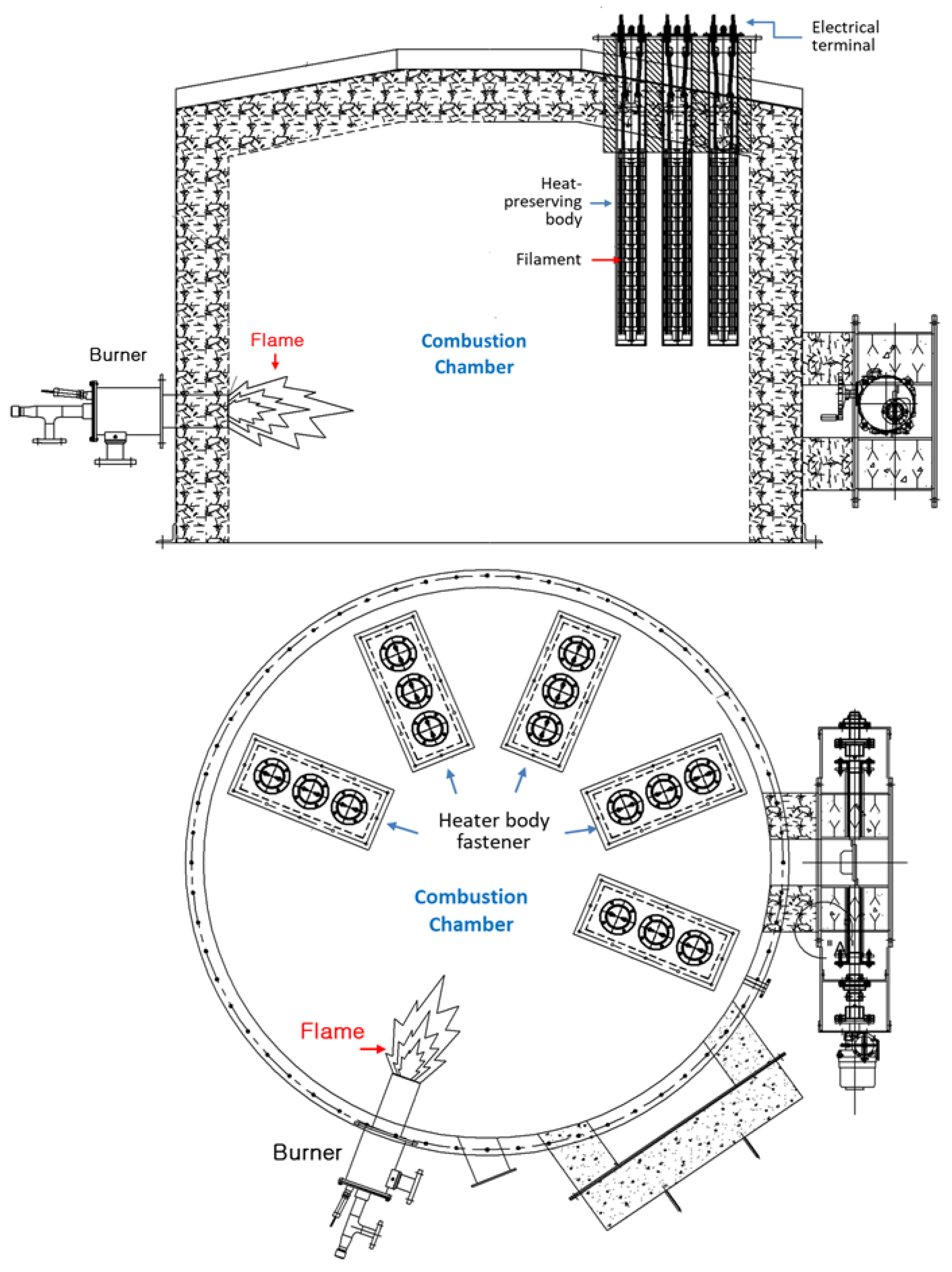
Figure 8.
Combustion chamber with a high heating element applied and the ceramic heat storage material.
Figure 8.
Combustion chamber with a high heating element applied and the ceramic heat storage material.
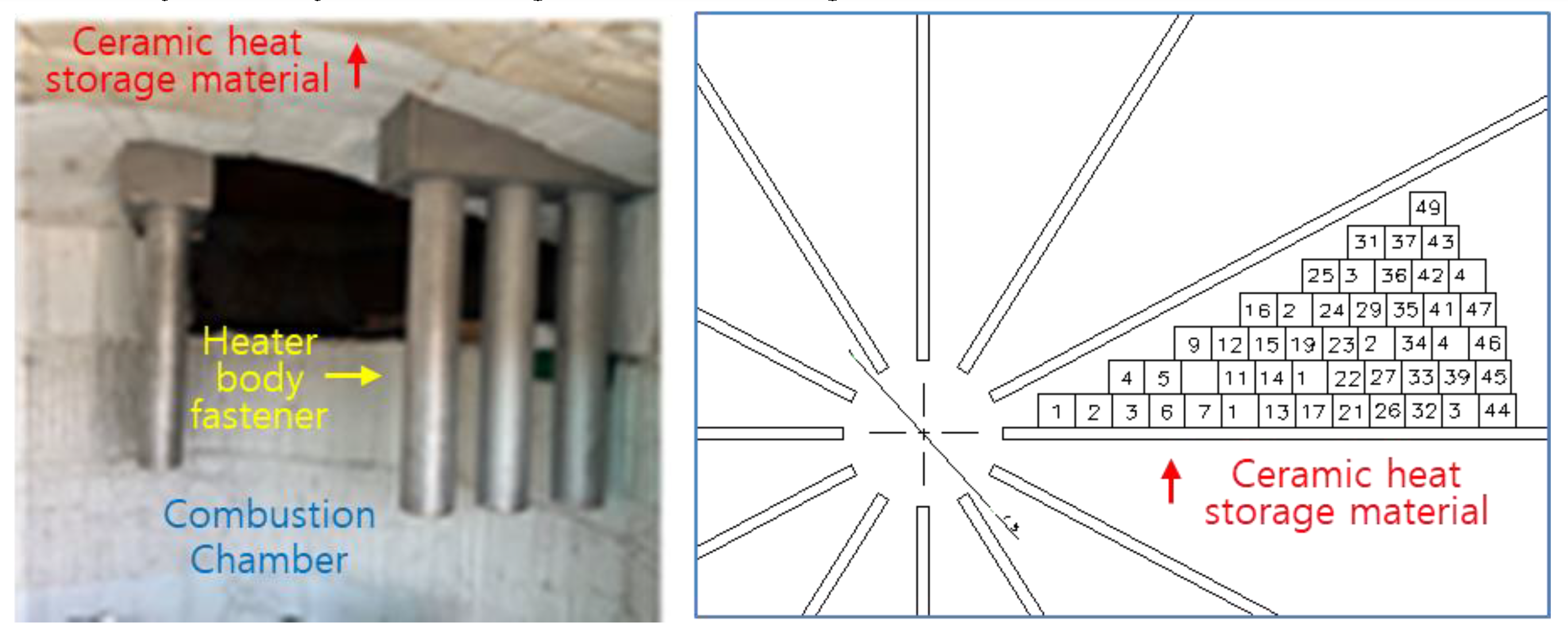
Figure 9.
Analysis of VOCs gas input and output conditions.
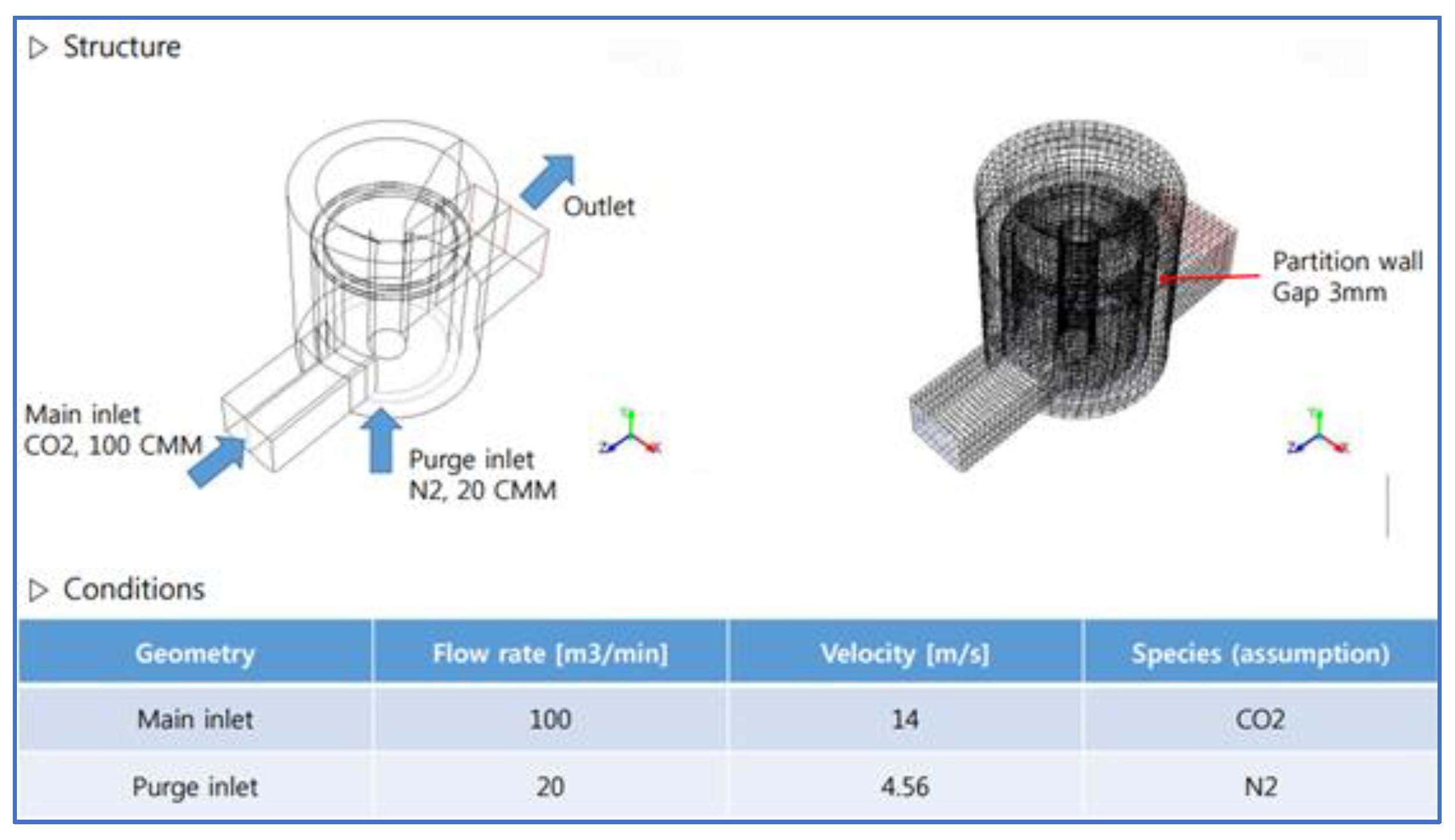
Figure 10.
Operation characteristics of the combustion chamber.
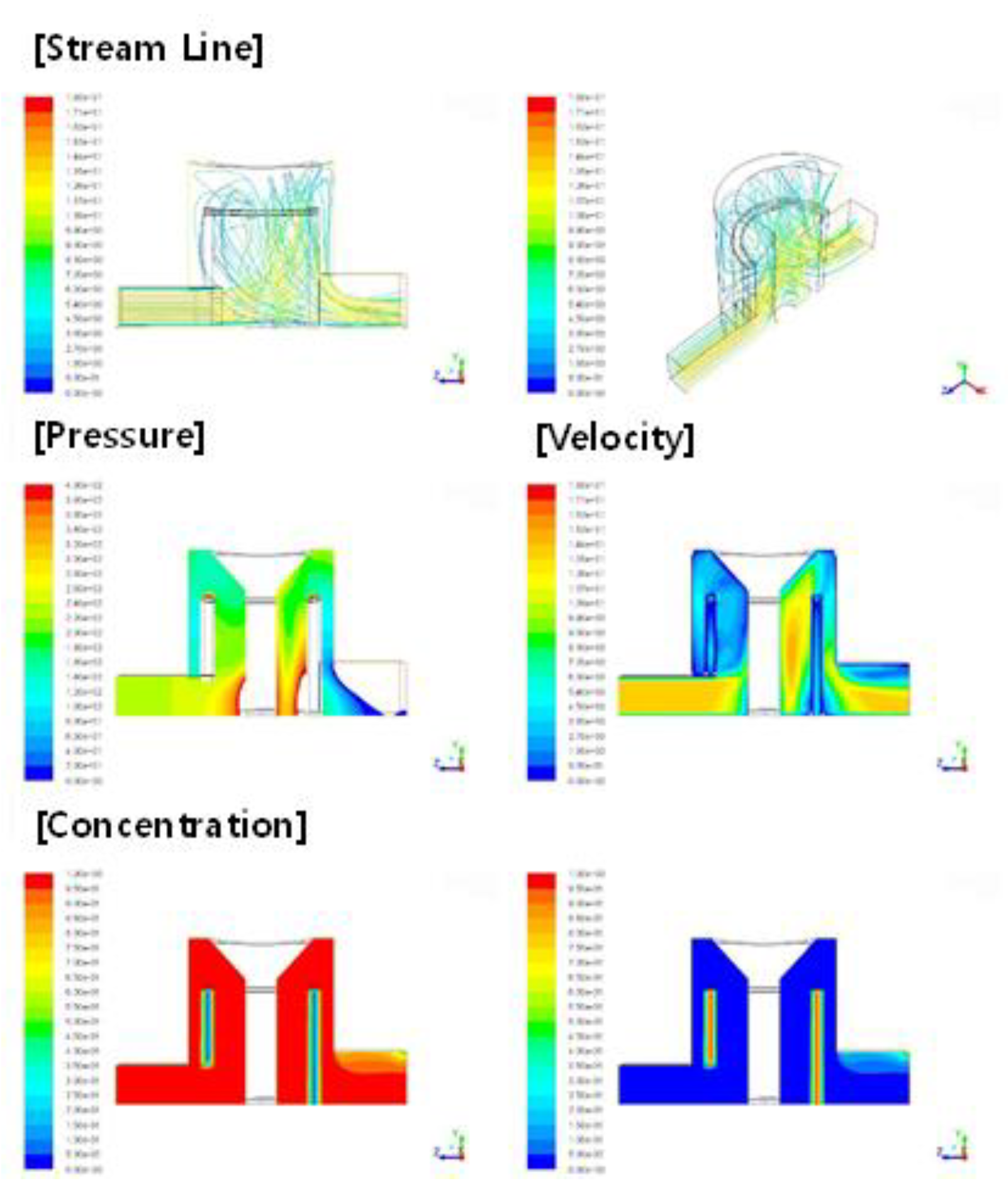
Figure 11.
Vector space for the air flow .
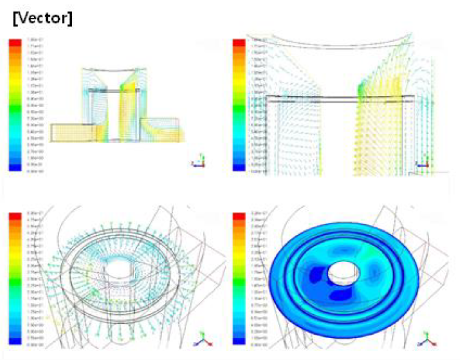
Figure 12.
Simulation results of various condition.
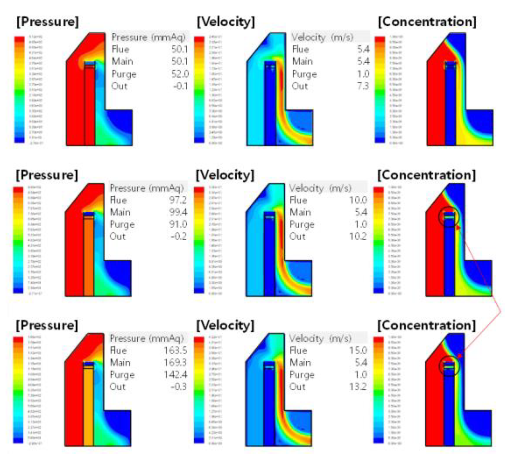
Figure 13.
Combustion chamber analysis.
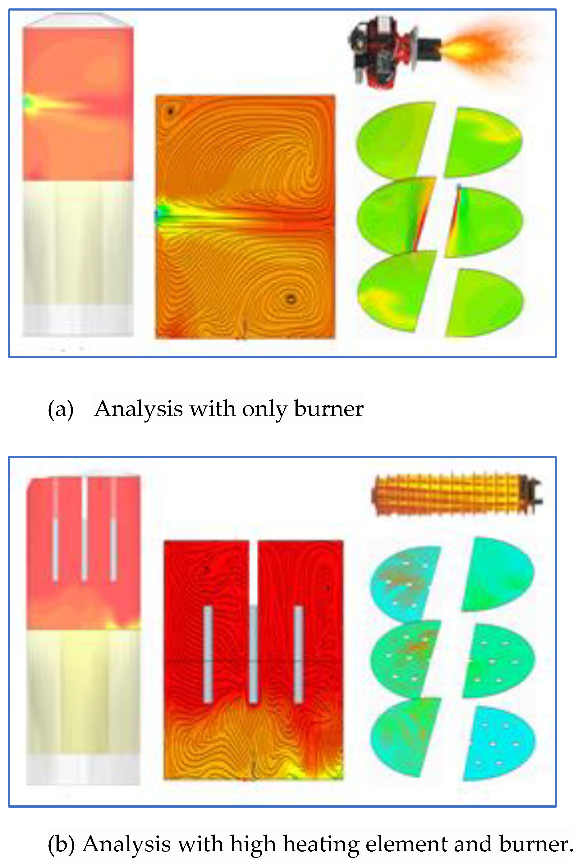
Figure 14.
VOCs concentration generated in the coating film system.
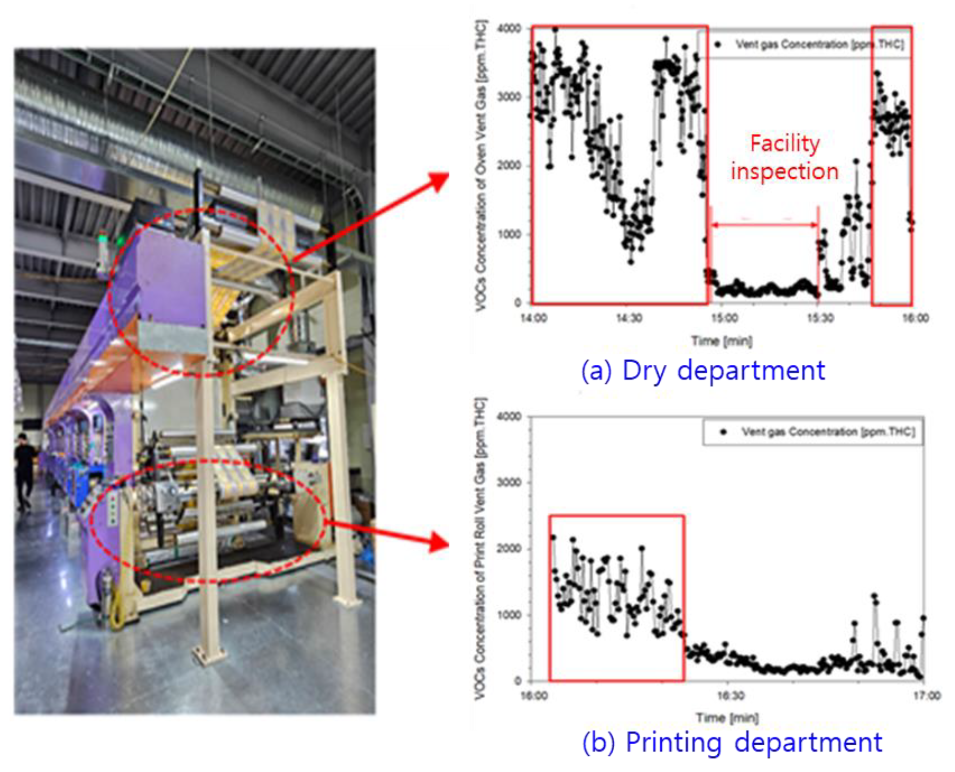
Figure 15.
Integration of experimental RTO configuration.
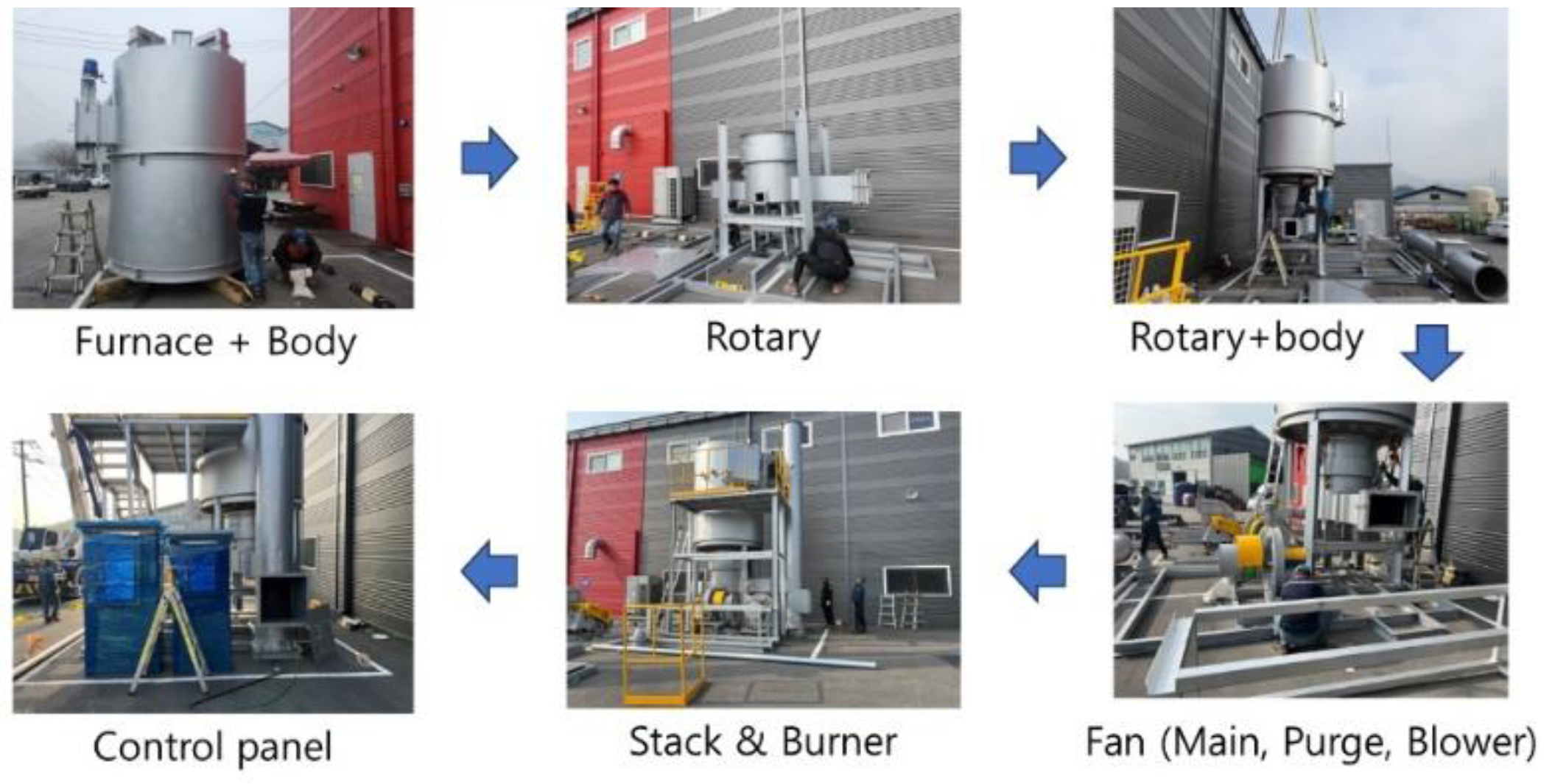
Figure 16.
Temperature characteristics according to the combustion chamber operation with only burner.
Figure 16.
Temperature characteristics according to the combustion chamber operation with only burner.
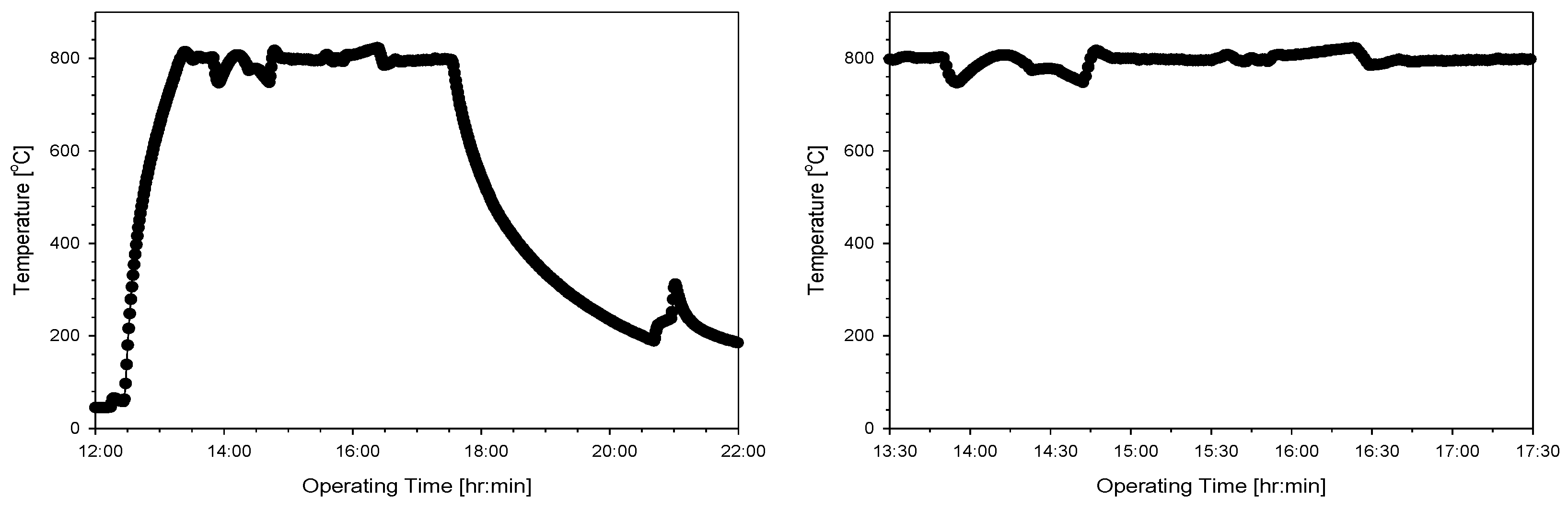
Figure 17.
Temperature operation of combustion chamber with the burner and the high heating element.
Figure 17.
Temperature operation of combustion chamber with the burner and the high heating element.
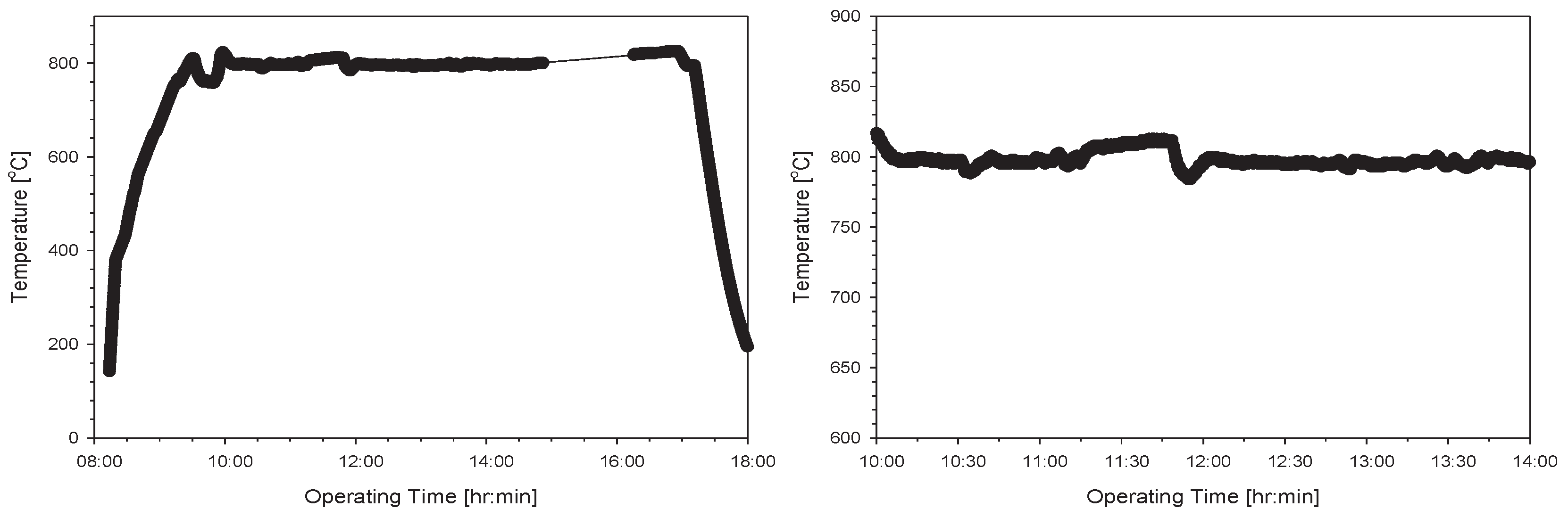

Table 1.
100 CMM RTO design specifications.
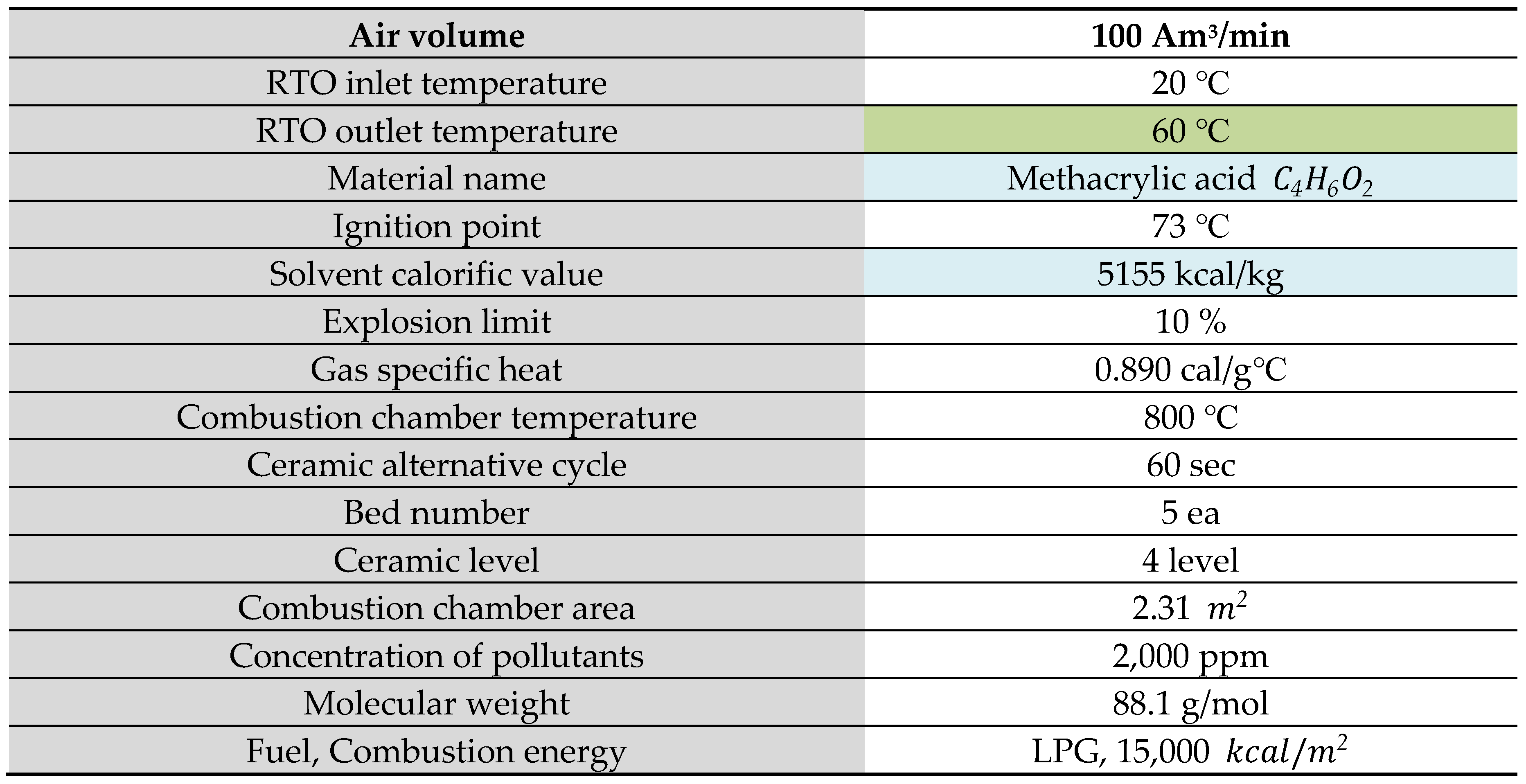
Table 2.
Result of simulating.
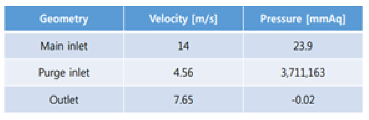
Table 3.
Average value of total hydrocarbons and VOCs reduction rate.
| Sortation | Forward stage (ppm) |
Backward stage (ppm) |
VOCs reduction rate (%) |
|---|---|---|---|
| THC | 1,575.24 | 33.58 | 97.89 |
| Nitrogen oxide | - | 3.90 | - |
Table 4.
Fuel reduction efficiency.
| Fuel using quantity | Traditional RTO (kWh) |
RTO with heating element(kWh) | Fuel reduction efficiency (%) |
|---|---|---|---|
| Test results | 56.413 | 44.032 | 21.95 |
Table 5.
VOC calorific value.
| Concentration (ppm) |
Emissions (kg/hr) |
Combustion heat (kcal/kg) |
Amount of heat burned (kcal/hr) |
|---|---|---|---|
| 2,000 | 43 | 5,155 | 221,544 |
Disclaimer/Publisher’s Note: The statements, opinions and data contained in all publications are solely those of the individual author(s) and contributor(s) and not of MDPI and/or the editor(s). MDPI and/or the editor(s) disclaim responsibility for any injury to people or property resulting from any ideas, methods, instructions or products referred to in the content. |
© 2024 by the authors. Licensee MDPI, Basel, Switzerland. This article is an open access article distributed under the terms and conditions of the Creative Commons Attribution (CC BY) license (http://creativecommons.org/licenses/by/4.0/).
Copyright: This open access article is published under a Creative Commons CC BY 4.0 license, which permit the free download, distribution, and reuse, provided that the author and preprint are cited in any reuse.


