
Submitted:
20 March 2024
Posted:
21 March 2024
You are already at the latest version
Abstract
Hard tissue apposition along the root canal walls is a slow, normally occurring physiological aging process. In response to tooth wear, local deposition of hard tissue may also occur in the pulp at a slow pace. Sometimes, the rate of hard tissue deposition acceleration may seem to be uncontrolled after dental trauma, autotransplantation, and orthodontic therapy, leading to rapid partial or total obliteration of the root canal space. This situation is called calcific metamorphosis (CM) or pulp canal obliteration (PCO). Although the incidence of pulpal necrosis in these teeth is believed to be infrequent, conventional endodontic therapy in severely calcified canals poses extreme difficulties and a higher risk for procedural accidents. This article aims to review the available approaches for the predictable negotiation of calcified canals and to introduce the buckling resistance activation test (BRAT) technique.
Keywords:
Calcification
; Pulp canal obliteration
; free hand approach
; guided endodontics
; Buckling resistance
1. Introduction
In the ideal root canal negotiation scenario, where the root canal is patent from the orifice to the apical foramen the challenge of root canal instrumentation is minimal. However, frequently root canals might not be patent but fibrotic or obliterated by denticles, nodules, pulp stones, secondary or reactionary dentin formation, diffuse calcifications, or anatomical blockages that may prevent uneventful negotiation and instrumentation (McCabe & Dummer, 2012).
Efforts to perform root canal treatment in teeth with obstructed access due to calcific deposits often encounter challenges. The negotiation of small, calcified canals is considered challenging in all available difficulty assessment forms (American Association of Endodontists 2010, Canadian Academy of Endodontics 2017, Falcon et al. 2001, Ree et al. 2003, Shah & Chong 2018, Essam et al. 2021). Attempting to identify the residual canal may necessitate the removal of substantial amounts of dentin, posing the risk of root fracture and perforation. A higher number of irretrievable instrument fractures and perforations are expected to occur in calcified root canals (Cvek et al. 1982, Dodds et al. 1985).
Root canal Calcification or Calcific Metamorphosis (CM), as defined by the American Association of Endodontists, denotes a pulpal response to trauma characterized by the rapid deposition of hard tissue within the canal space, also known as the obliteration of the pulp canal (Glossary of Endodontic Terms, 2020). This phenomenon, alternatively termed Dystrophic Calcification, Diffuse Calcification, and Calcific Degeneration, is contingent upon the extent of luxation injury and the stage of root formation.
Radiographically, CM is categorized into partial calcification, where the pulp chamber is not visible, and the canal is markedly narrowed but visible, and total radiographic calcification, where both the pulp chamber and canal are hardly or not visible. Despite the radiographic appearance, histological and micro-ct studies suggest the presence of a narrow canal, regardless of its visibility on radiographs (Figure 1 and Figure 2).
Two distinct types of pulp calcification have been suggested to exist (Goga, 2008): diffuse or linear calcifications predominantly found in the radicular pulp (Figure 3) and pulp stones (denticles) more common in the coronal region (Figure 4 and Figure 5).
The denticles, classified as true or false based on structure, exhibit morphological distinctions rather than chemical differences. True denticles resemble dentin with dentinal tubules, odontoblastic processes, and few odontoblasts, while false denticles consist of concentric layers of calcified tissue surrounding a central cellular area, which may be necrotic and act as a nidus for denticle formation. Based on location, denticles are categorized as embedded, interstitial, adherent, or free (Goga et al., 2008).
Pulp tissue calcification can be further classified as total or partial, with total obliteration being rare and usually accompanied by a thin filament of pulp tissue (Oginni et al., 2007). (Figure 1). Partial obliteration, primarily affecting the pulp chamber, has minimal impact on the root canal and apical region. An additional classification distinguishes between localized obliteration, often associated with trauma, and generalized obliteration, typically attributed to aging.
Localized obliteration, linked to traumatic events such as crown and root fractures, tooth luxation, jaw fractures, tooth replantation, and endodontic procedures, exhibits varying prevalence rates ranging from 3.8% to 24% (Robertson,1998). Generalized obliteration, occurring as part of the aging process, is observed in older individuals and may result in a completely obliterated or hairline-thin pulp chamber, often accompanied by attrition, deep carious lesions, and deep restorations (Maeda 2020).
Pulp canal obliteration is quoted as being the most common sequel of root fracture and can be found in 69-73% of root-fractured incisors (Saroğlu & Sönmez 2002). Bauss et al. (2008a) studied the prevalence of pulp stones and pulp obliteration in patients with Marfan syndrome and the authors studied the influence of age, gender, dental arch, tooth type, condition of the tooth, and presence of calcifications (Bauss et al., 2008b). The results indicated that pulp stones and pulp obliteration were commonly observed in older subjects but found frequently even in younger adults with Marfan syndrome.
Treating calcified canals poses challenges due to the narrowed pulp chamber and canal lumens, complicating access location, negotiation, cleaning, and shaping procedures. Calcification increases the risk of procedural accidents during cleaning and shaping procedures. This paper aims to review the available treatment options for the management of calcified root canals, to suggest useful clinical aids, and to introduce a new technique for calcified canal negotiation.
2. Radiographic Interpretation of Root Canal Calcification
The radiograph serves as a valuable tool in root canal therapy, aiding not only in diagnosis but also in assessing various aspects such as curvature, size, number, shape, and degree of calcification of pulp canals. However, the apparent width of a canal on a periapical radiograph may not always accurately represent its true size clinically. For instance, a canal that appears clear on a radiograph might be challenging to locate or navigate with endodontic instruments. Conversely, a canal that seems calcified on the radiograph may still be manageable clinically. Kuyk and Walton's study (1990) compared the radiographic appearance of root canal size to its actual diameter. Interestingly, they found that while all specimens had canals histologically, seven roots showed no visible canal space radiographically. This challenges the notion that canals may calcify, suggesting that even if a canal appears completely calcified on the radiograph, there may still be enough tissue within it to cause endodontic issues if that tissue becomes necrotic or inflamed. In their study, Kuyk and Walton (1990) encountered sections with no radiographic canal space, including roots of maxillary molars, mandibular incisors, and cervical thirds of maxillary incisors. The absence of visible canals could be due to various reasons such as difficult regional anatomy, calcification of the canal, or division of a single canal into smaller ones. Additionally, in some cases, there were no apparent explanations for the lack of visibility, suggesting that primary and secondary dentin thickness could obscure small canal spaces. It's crucial to note that despite radiographic visibility, the actual dimensions of canals may vary significantly, leading to challenges in treatment. Some canals may be apparent on radiographs but difficult to locate or navigate clinically, while others may not be visible radiographically but are manageable during treatment. These discrepancies underscore the importance of clinical judgment and meticulous treatment planning in root canal therapy (Kuyk & Walton, 1990).
3. Why Are There These Variations?
It is possible that what appears to be a canal space may totally or partially be an artifact of degrees of mineralization of dentin peripheral to the pulp. In other words, it might be hypothesized that regular or irregular secondary dentin that has formed on the canal walls is considerably less radiodense than primary dentin; this would give the radiographic appearance of a diameter of the canal that was smaller (Kuyk & Walton, 1990). Relative densities of dental hard tissues can be precisely determined using very thin ground sections exposed to soft X-rays, a process termed microradiography. This technique was utilized by Mjor (1966) who micro-radiographed human coronal dentin and noted that there were marked variations in the mineralization of the dentin surrounding the pulp chamber. His studies did not include radicular dentin. Complete radiographic obliteration of the pulp space doesn’t necessarily mean the absence of a canal. In the majority of cases the sensitivity of conventional radiographs is too low to allow their image to be discernible (Patersson & Mitchell 1965, Schindler & Gullickson 1988, Torneck 1990).
4. CBCT Identification of Calcified Canals
Several recent articles have highlighted advancements in technology regarding the utilization of CBCT for identifying and managing calcified canals. These advancements include offering supplementary information to aid clinicians in locating canals or utilizing the data to create a stent for precise alignment and depth control of the bur. Studies, such as those by Soares de Toubes et al. (2012), Neelakantan et al. (2010b, 2010a), and Matherne et al. (2008), have demonstrated CBCT's superior sensitivity in canal detection compared to conventional radiography. Matherne et al. (2008) specifically found that endodontists missed identifying root canals in 40% of cases when compared to CBCT. However, there is limited evidence regarding CBCT detection rates concerning canal diameter. The influence of CBCT voxel size on canal detection has been proposed, with smaller voxel sizes theoretically providing higher resolution for detecting fine structures like constricted root canals. Yet, studies, such as that by Vizzotto et al. (2015), suggest that examiner experience may outweigh voxel size in diagnostic reproducibility. Additionally, the choice of CBCT view size impacts resolution, with smaller fields of view offering greater resolution due to the smaller area being projected over the detector. Optimizing CBCT exposure is crucial to balance dose reduction while maximizing diagnostic yield, particularly in cases requiring identification of calcified canal systems. Higher resolution, achieved through smaller field-of-view images, is essential for such cases. However, resolution alone doesn't dictate canal discrimination; contrast plays a significant role. Lowering the kV improves contrast but increases the noise-to-signal ratio, necessitating a balance between spatial resolution, contrast, and noise for effective detection. CBCT provides valuable depth measurements for canal detection, facilitating predictable access during treatment. If a canal isn't found at the expected depth, clinicians can adjust their search laterally, streamlining the access procedure and reducing treatment time (Dodd 2018).
5. Anatomy of the Calcified Canal
The pulp space diminishes throughout life by the deposition of regular secondary dentine. The pulp space is further reduced by reactionary and reparative dentine (formerly classified together as tertiary or irritation dentine), which is laid down to reduce the porosity of dentinal tubules opened to the mouth by caries, trauma, or dental treatment, or to heal frank pulpal exposures. This occurs most commonly in pulp horns and on the floor and roof of the pulp chamber in molars, which may be converted from a large rectangular cavern in the young to a flat disc in the elderly (Holcomb & Gregory, 1967). In anterior teeth, the pulp retreats progressively in a cervical direction, becoming narrower and often leaving no soft tissue within the crown at all (Amir et al. 2001). Concentric towards the center deposition of calcified tissue is often most marked in the coronal reaches of the canal system, with deeper areas of root canals remaining widely patent even into very old age (Figure 1 and Figure 2). Cumulative insults reduce the vascularity and cell content of the pulp, with a concomitant increase in fibrosis. These changes are again mostly confined to the coronal reaches of the canal system where external irritants have the greatest impact (Holcomb & Gregory, 1967). Generally, pulp fibrosis or atrophy is referred to as a histologic change that is not clinically discernible unless the pulp space is accessed, so its value as a diagnostic term is questionable. Pulp calcification, however, is usually clinically detectable before treatment and can directly affect the prognosis of treatment, in that severely calcified teeth are predisposed to tooth perforation during the search for canals, or instrument separation. Calcification, per se, does not necessarily imply that progressive inflammation of the pulp or pulp necrosis will occur. Pulp necrosis is found in less than 7% of traumatically induced calcified pulps (Robertson et al. 1996, Andreasen 1972). Lastly, the mineral content of the tertiary dentin represents more than just calcium hence the term pulp canal mineralization would be a more accurate term (Oginni & Adekoya-Sofowora 2007, Holcomb & Gregory1967).
Moreover, diffuse Calcifications are usually formed as amorphous unorganized linear columns lying parallel to the blood vessels of the pulp and they are like the calcifications seen in other tissues of the body following degeneration (calcific degeneration) (Figure 3). Fibrillar calcifications are one of the manifestations of the regressive changes that the pulp undergoes. The incidence of pulp calcifications seems to be relatively high, especially based on microscopic examination because many of the calcifications are not of sufficient size to be discernible in radiographs. Calcifications seem to increase with age, with about 90% of those of 50 yr or older being reported as affected. As teeth age, vascular, lymphatic, and nerve supplies decline, and fibroblasts decrease in size and number (Maeda 2020). A reduction of 15.6% in crown odontoblasts, a reduction of 40.6% in root odontoblasts, and a decreased secretory activity have been observed, suggesting that the reparative capacity of the pulp is compromised with aging. The age-related changes include increases in cross-linkages and the number of collagen fibers, lipid infiltration, and calcifications. Despite many studies having investigated the mechanisms underlying these age-related changes, we still have much to learn about the biological control mechanisms responsible for cellular activity and survival throughout life. The mechanism of hard tissue formation during CM is not yet clear. Several hypotheses have been proposed to explain this phenomenon. Torneck (1990) hypothesized that the deposition of hard tissue is either because of stimulation of the pre-existing odontoblasts or by loss of their regulatory mechanism. On the other hand, Andreasen et al. (1987) described CM as a response to severe injury to the neurovascular supply to the pulp, which after healing leads to accelerated dentin deposition and is closely related to the loss and re-establishment of the pulpal neural supply. Neither mechanism has been proven or studied, and further investigation is required to provide an evidence-based understanding of this occurrence. Calcific metamorphosis is characterized by osteoid-like tissue that is produced by the odontoblasts at the periphery of the pulp space or can be produced by undifferentiated pulpal cells that undergo differentiation because of the traumatic injury (Amir at al. 2001, Pissiotis et al. 2007). This results in a simultaneous deposition of dentin-like tissue along the periphery of the pulp space (root canal walls) and within the pulp space proper (root canal). These tissues can eventually fuse, producing the radiographic appearance of a root canal space that has become rapidly and completely calcified (Paterson & Mitchell 1965). Clinically, there is usually a clear distinction between the calcified irregular tissue and the peripherical dentinal walls reflecting the different histological characteristics and mechanisms of formation of the tissues obliterating the pulp space. Under the magnification and illumination provided by a dental operating microscope, these tissues reflect the light in different ways. Usually, when searching to negotiate a calcified canal under the dental operating microscope the operator evaluates the different dentine colors and textures on the axial view plane. In a single-rooted calcified tooth, the concentric axial orientation of the dentinal tubules is visible under the microscope giving a concentric radial appearance (Figure 6 and Figure 7). If not visible, transillumination from a different angle can improve intracanal visibility (Figure 6).
This concentric radial appearance points to a greyer area in the centre that demarcates the area of secondary and reactionary dentine formation occluding the canal space. This irregular dentine gives a different reflection under the microscope with a more greyish appearance. In the centre of the irregular calcified tissue usually the thin canal space lies. Because of the debris production during deep troughing with burs or ultrasonics, a white spot is created over the canal space dimple demarcating the calcified canal orifice (Figure 6 and Figure 7).
In multirooted teeth, the determination of the calcified pulp chamber position as well as the location of the calcified root canal entrances is even more challenging. Based on the anatomical study of 500 teeth, Krasner and Rankow (2004) proposed some laws for aiding the determination of the pulp chamber position as well as the location and number of root canal entrances in each group of teeth.
- Law of centrality: The floor of the pulp chamber is always located in the center of the tooth at the level of the cemento-enamel junction (CEJ).
- Law of concentricity: The walls of the pulp chamber are always concentric to the external surface of the tooth at the level of the CEJ, i.e., the external root surface anatomy reflects the internal pulp chamber anatomy.
- Law of the CEJ: The distance from the external surface of the clinical crown to the wall of the pulp chamber is the same throughout the circumference of the tooth at the level of the CEJ;
- Law of symmetry 1: Except for maxillary molars, the orifices of the canals are equidistant from a line drawn in a mesial-distal direction, through the pulp chamber floor.
- Law of symmetry 2: Except for the maxillary molars, the orifices of the canals lie on a line perpendicular to a line drawn in a mesial-distal direction across the center of the floor of the pulp chamber.
- Law of color change: The color of the pulp-chamber floor is always darker than the walls.
- Law of orifice location 1: The orifices of the root canals are always located at the junction of the walls and the floor.
- Law of orifice location 2: The orifices of the root canals are located at the angles in the floor-wall junction.
- Law of orifice location 3: The orifices of the root canals are located at the terminus of the root developmental fusion lines.
In calcified pulp chambers, the floor wall junction and the root developmental fusion lines are not readily visible under the microscope. If the calcified structures are loosely attached to the pulp floor, removing them with ultrasonics can reveal the developmental fusion lines that will lead to the canal orifices (Figure 4). If the calcified tissue is firmly attached to the pulp floor, the anatomy is altered, and the developmental fusion lines are hidden. Canal orifices can be located by stepwise excavating the calcification following the laws of orifice location. The floor wall junction and the grey developmental fusion lines can be revealed with deep troughing with ultrasonics or long shafted burs. In the angles of the floor wall junction and the terminus of the developmental fusion lines, the calcified canal orifices can be detected. Calcified maxillary molars orifice detection benefits more by searching for the floor wall junction angles and the dark developmental line demarcating the perimeter of the chamber. The canal always originates from this perimetrical line. In mandibular molars and all premolars, the developmental fusion lines of the pulp floor will guide the operator to the calcified canal orifices. The axial walls have a dark yellow appearance, the pulp floor is grey, the developmental lines are dark grey, and the calcified tissues are light yellow, opaque or white. Colour differences in the pulp floor are well recognised as a method to locate canals but the differences in colour are related to the relative hydration of the root canal system. When the pulp chamber is dried, differences between different shades of dentine are more difficult to detect. Conversely, an overly wet chamber obscures details of the chamber floor. When moistened the dentine seems to show a greater contrast between grey dentine shades of the pulpal floor and the more opaque, white shades of secondary dentine (Dodd 2018).
After identifying and removing the calcified tissues, the root developmental fusion lines and the floor wall junction become visible. Finding the canal orifice is the first step to negotiate inside a calcified canal.
6. Traditional Negotiation of Calcified Canals
Root canal treatment of calcified canals requires proper knowledge of the root canal anatomy and the variations that can be seen in it. Typically, small files are required for initial pathfinding; however, these files lack the rigidity required to transverse restricted spaces and can often buckle or fracture when used with vertical watch-winding strokes. The result will be damaged files without being able to negotiate through the calcified tissue. A suggested approach is to alternate between size 8 and 10 K-files with a gentle watch-winding motion of minimal vertical pressure and regular replacement of the instruments before fatigue occurs (Molven 1973). Another specialized technique involving K files with modified tips has been devised for penetrating constricted canals. The tip of a #10 K file is diagonally sliced to achieve increased thinness. This modified K file, characterized by a finely tapered tip and appropriate stiffness, can exhibit effective traversal through constricted or calcified canals, demonstrating a high penetration potential (McCabe & Dummer 2012).
Recently, various specially designed ‘pathfinding’ instruments were introduced to be used in difficult negotiation scenarios. These instruments are manufactured by special work-hardened or fiber-reinforced stainless steel alloy and have various designs to enhance their rigidity and buckling resistance. Some of these glide finder files have modified tips, tapers, and cross-sectional designs to penetrate through anatomical impediments and calcified structures. Instruments characterized by a reduced flute design, such as the Canal Pathfinder (JS Dental, Ridgefield, Conn), or those featuring enhanced shaft strength like the Pathfinder CS (Kerr Manufacturing Co.), demonstrate improved efficacy in penetrating highly calcified root canals. C+Files (Dentsply, Tulsa, OK, USA) are suggested to be advantageous for the initial instrumentation of calcified root canals, incorporating a cutting tip for engaging dentin. D-Finder files (Mani, Japan) can be used effectively to penetrate through fibrotic or calcified canal pathways. They are manufactured with special 18-8 hard fiber stainless steel making the files stiffer than K-files and have a special design with a D-cross sectional shape, fewer flutes, and a non-cutting tip offering great negotiation potential.
In addition to the glide finder files, various long-shafted burs were introduced for deep troughing along the long axis of the obliterated root. Long-neck round burs (LN-bur) such as those from Caulk/Dentsply (Tulsa, OK, USA) and extended-shank round burs like the Mueller bur (Brasseler, Savannah, GA, USA) facilitate the identification of orifices in calcified canals. Furthermore, the Munce Discovery bur (CJM Engineering, Santa Barbara, CA), akin to the Mueller bur but distinguished by a stiffer shaft and available in smaller head sizes, presents an alternative option. The extended shank of these burs strategically positions the handpiece away from the tooth, enhancing the clinician's visibility during this intricate procedure.
The long-shafted Munce burs are used in a crown-down approach of 1mm increments (Figure 9 and Figure 10). Usually, the first bur to be used is the 1.2mm round bur without irrigation. After the first stroke, the debris is flashed away and the dentine is dried with Stropko air dryer or paper points. The dried dentine is moistened with a wet microbrush and visualized under the magnification and light provided by a Dental operating microscope. Different colors of moist dentine can be recognized. The axial canal walls are usually light yellow, and the calcified canal space is darker or gray. The calcified orifice is checked with a hand file for possible binding points. Special Stainless steel stiff glide finder files are used for this procedure. These files can accommodate greater vertical pressure before buckling occurs. If no binding is detected, a 1mm round bur is used the same way for a further 1mm deeper troughing. The canal is irrigated and checked again for possible binding points. If Failure to negotiate the calcified canal, a smaller round bur of 0.8mm diameter is used further deeper for 1 mm increment the same way by keeping the shaft of the bur always centered. The canal is irrigated again and checked for possible binding points. The same procedure is repeated with burs of 34mm in length and decreasing sizes of 0.6mm and 0.5 mm diameters for 1 mm increments. At this point, a second radiograph is necessary to verify the proper centering of the burs. Care should be taken not to deviate from the long axis of the root. Multiple radiographs might be needed for the continuous control of the tooth's long axis. Deep troughing with burs inside the root to find the calcified canal trajectory is always challenging and might result in many complications when attempted without guidance. The undesirable complications range from file breakage, ledging, and false canal creation to more severe perforation damage or removal of excessive tooth structure rendering the obliterated tooth non-restorable. Alternative to the long-shafted burs, ultrasonic tips are also recommended for the detection and negotiation of obliterated canals, especially when working under magnification. They offer enhanced visibility under the microscope and they can be used in conjunction with methylene blue dye for very detailed troughing of root dentin. For deeper penetration, the Buckling Resistance Activation Test (BRAT) technique can be used.
7. Buckling Resistance Activation Test (BRAT) Negotiation of Calcified Canals
Owing to the advancement of microscope dentistry, clinicians are more likely to find hidden calcified existing root canals. After locating the canal orifices, canal exploration, and negotiation should follow for chemo-mechanical preparation. During these initial procedures, the tiny, constricted calcified canal is a challenging situation. Even by using small files, sometimes, it is not possible to negotiate and pass through the sclerotic root canals. Usually, small stainless-steel files are used for the exploration of narrow and calcified canals. However, only a few studies have investigated some of the mechanical properties of these instruments (Allen et al. 2007). A sufficient buckling resistance enables clinicians to easily penetrate an existing canal, which is usually narrow and occasionally sclerotic. An instrument that is too weak cannot negotiate a tight orifice and canal area, and thus, files need to have an appropriate buckling resistance.
Buckling is defined as a sudden sideways deflection of an instrument, which occurs when compressive force overwhelms the instrument’s resistance. Small instruments with low buckling resistance are susceptible to deformation and cannot penetrate apically in the calcified canal. Proper buckling resistance may facilitate both the exploration of the canal orifices and the negotiation of narrow canal walls. However, sometimes, files having a strong buckling resistance are stiff, and the power of stiffness might be more than that needed clinically. The use of stiff instruments can result in some canal aberrations such as ledges and perforations during the negotiation and may then jeopardize the clinical outcome. Because small conventional K-type SS instruments (i.e., sizes #06, 08, and 10) usually show reduced resistance to buckling, they are sometimes unable to negotiate and penetrate narrow calcified canals to full working lengths (Figure 9).
Recently, small-size NiTi rotary instruments that are engine-driven have become available specifically for glide path preparation but their use is limited to patent canal trajectories. In calcified and sclerotic canals small size NiTi instruments with non-cutting tips will succumb and fail if attempted to penetrate through the calcification. In a calcified canal negotiation, the instrument tip is an important parameter. Instrument tips have been described as cutting, non-cutting, and partially cutting although there is no clear distinction between the types. The tip has two functions. One function is to enlarge the patent canal, the other function is to guide the file through the patent canal. Usually, file breakage can occur by applying excessive torque while attempting to enlarge a canal that has a smaller diameter than the non-cutting portion of the file tip. If the canal dimensions are smaller than the file tip, a cutting tip should be used. If the canal is larger than the tip, a file with a less effective cutting tip will help prevent transportation (McSpadden 2007). In calcified canals, the canal is always smaller than the file tip. Pressing against the calcified canal orifice with a non-cutting tip can induce increased torsional loading without any advancement of the file inside the constricted canal. A cutting tip will be more useful when trying to negotiate calcified canals. Tips with greater cutting efficiency can be used to reduce stresses on the file when they work against a constricted or calcified canal. A file with increased cutting efficiency in the tip will be able to carve its path through the calcified root canal. An efficient file requires less pressure, torque, and time to cut dentine (McSpadden 2007). The angle and radius of its leading edge and the proximity of the flute to its actual tip end determine the cutting ability of a grinded file tip. Recently electrical discharge machining (EDM) was used to manufacture endodontic files. The shape of the file is formed by electric spark erosion of the NiTi wire. EDM manufacturing alters the molecular structure of the file’s surface potentially strengthening the file without affecting its flexibility (McSpadden 2007). The result is a rough surface with increased cutting efficiency (Figure 8). The difference between grinded file tips and EDM file tips can be seen in Figure 8.
The EDM tip when pressed against the calcification carves its way through, creating an initial dimple in the calcified canal orifice (Figure 9h,j,i). The carving of the pilot dimple is facilitated with the use of a continuous chelation irrigation technique (Figure 9e).
Figure 9.
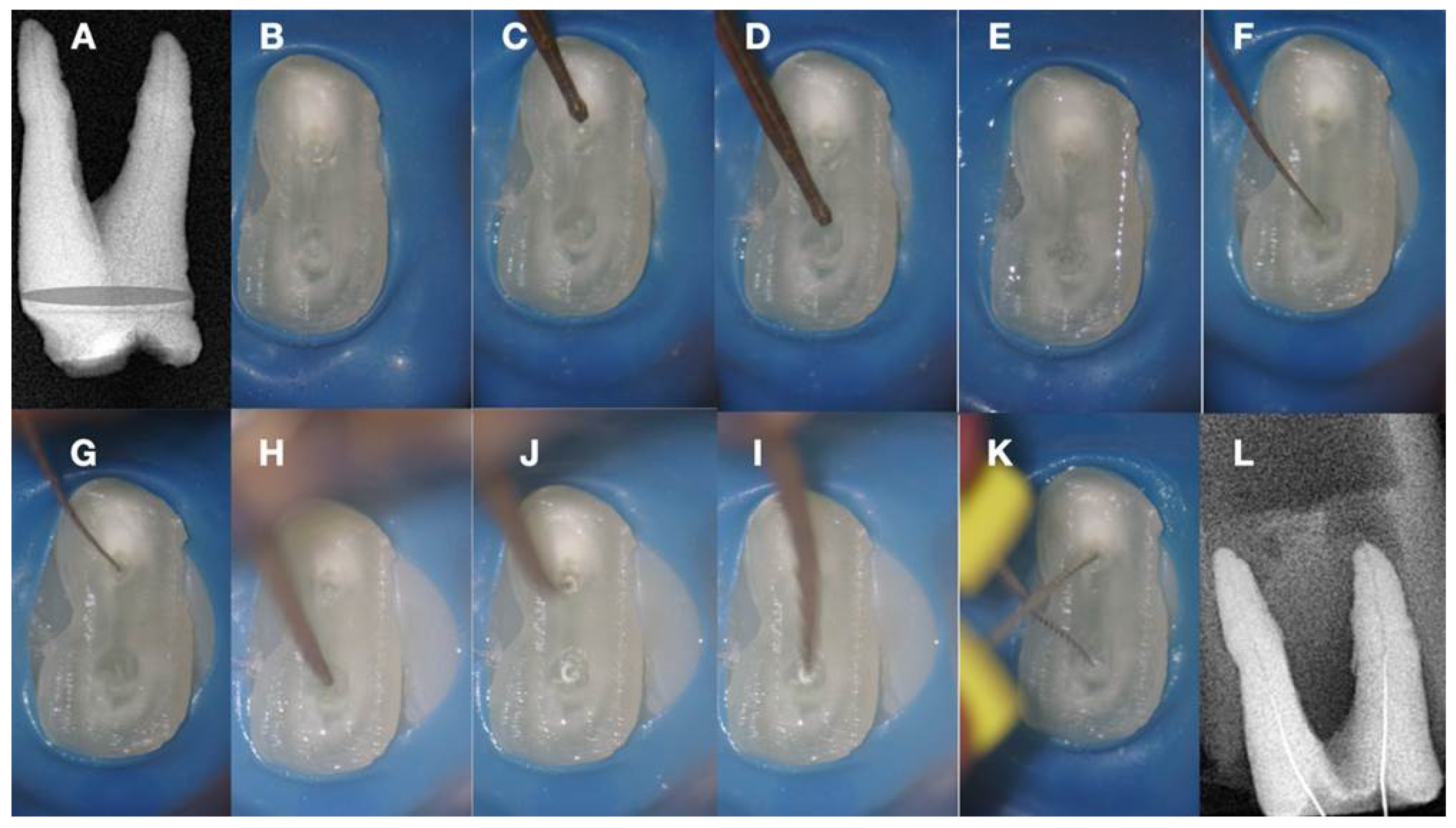
a. Radiographic image of an extracted partially calcified maxillary premolar, b, magnified view at the level of the axial cut (grey area in a), c, & d. creation of initial access dimple in the white spot indicating the calcified orifice, e. continuous chelation of the cut dentinal surface, f & g. initial unsuccessful attempt to negotiate the calcified canal orifices with D- finder files iso 08, h. Fitting of the tip of an EDM file (Hyflex EDM -one file, Coltene) in the dimple without activation, j & i. On-spot buckling activation test (BAT) negotiation of the EDM files, k. negotiation of the 08 d-finders inside the calcified canals after the BAT negotiation technique removed coronal calcified canal obstructions, l. radiographic verification of calcified canal negotiation.
Figure 9.
a. Radiographic image of an extracted partially calcified maxillary premolar, b, magnified view at the level of the axial cut (grey area in a), c, & d. creation of initial access dimple in the white spot indicating the calcified orifice, e. continuous chelation of the cut dentinal surface, f & g. initial unsuccessful attempt to negotiate the calcified canal orifices with D- finder files iso 08, h. Fitting of the tip of an EDM file (Hyflex EDM -one file, Coltene) in the dimple without activation, j & i. On-spot buckling activation test (BAT) negotiation of the EDM files, k. negotiation of the 08 d-finders inside the calcified canals after the BAT negotiation technique removed coronal calcified canal obstructions, l. radiographic verification of calcified canal negotiation.
The initial dimple is deepened progressively in a crown-down sequence until a patent pathway is met and confirmed (Figure 9 and Figure 10). Total obliteration of the canal space is very rare.
Figure 10.
Buckling Resistance Activation Test (BRAT) negotiation of calcified canals graphic explanation a. Long-shafted bur access cavity preparation, b. continuous chelation concept irrigation and D-finder negotiation test, c. long shafted access bur of smaller diameter insertion without activation (tactile feedback), d. single stroke activation of the bur (Tactile Controlled Activation), e. continuous chelation concept irrigation and D-finder negotiation test. If no negotiation continue to the next step, f. EDM or Active tip file placement inside the access dimple without activation, g. Activation of the EDM file at 500rpm/3NCM and apply vertical axial pressure against the calcified canal entrance (long press-release twice), h. continuous chelation concept irrigation and D-finder negotiation test. If no negotiation continue to the next step, i. EDM or Active tip file placement deeper inside the dedicated access dimple without activation, j. activation of the EDM file at 500rpm/3NCM and apply vertical axial pressure against the calcified canal entrance (long press-release twice). As the file goes deeper inside the root the buckling resistance of the file is increased because the lateral walls won’t allow the file to buckle and succumb. The axial pressure is transported to the file tip allowing the file to penetrate, k. continuous chelation concept irrigation and D-finder negotiation test. If no negotiation continues to the next step, l. EDM or Active tip file placement deeper inside the dedicated access dimple without activation, m. activation of the EDM file at 500rpm/3NCM and apply vertical axial pressure against the calcified canal entrance (long press-release twice), n. continuous chelation concept irrigation and D-finder negotiation test, o & p. If no negotiation repeats the previous steps.
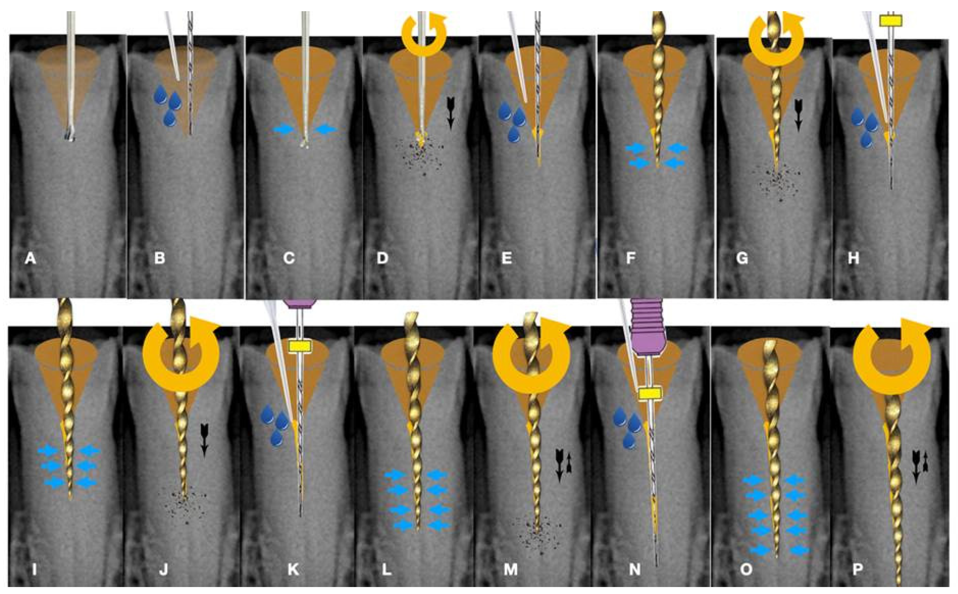
Usually, there is a tiny canal pathway of less resistance than the sclerotic walls. An efficient tip of an instrument with good dynamic buckling resistance will be able to penetrate through tough calcifications by following the path of least resistance. As the instrument goes deeper inside the root the buckling resistance of the instrument is increased because the lateral canal walls will not allow the instrument to buckle. Any axial pressure applied will be transported to the file tip. The step-by-step progression of a rotary file through the calcification is described in Figure 10.
This type of calcified canal negotiation can be called dynamic buckling resistance activation test (BRAT) negotiation. BRAT negotiation is defined as the activation of an engine-driven file with an active or dynamic tip against the conditioned calcified tissue that is blocking the canal trajectory. The tip of the engine-driven instrument is attached to the calcification point without activation. The instrument is activated according to the manufacturer’s instructions, and the file is pushed in an axial direction against the calcification (long press and release). The lateral buckling movement of the file is restrained by the canal walls. When the progression of the file is achieved, the file is removed from the canal and the canal is checked for patency with a hand file. If patency is achieved, then standard root canal treatment procedures can be continued. If no patency is achieved the same procedure can be attempted deeper inside the calcification (Figure 10). In Figure 11, Figure 12, Figure 13 and Figure 14 initial negotiation through the calcified canal orifices was done with the BRAT technique until canal patency was met. The conditioning of the calcified tissue blocking the canals for the BRAT technique to be effective is preferably accomplished with the continuous chelation concept.
8. The Continuous Chelation Concept
Pulp calcifications consist of both organic and inorganic components. The calcium present in hydroxyapatite (Ca3(PO4)5OH) crystals is one of the main inorganic elements of pulp calcifications. For penetration through the calcifications, the chelating agents are chosen due to their direct action on calcium ions. Any change in the calcium ratio can significantly alter the original proportion of organic and inorganic components, which can alter the calcification permeability, microhardness, and solubility (Juárez-Gallegos et al. 2023). During calcified canal penetration, altering the calcified substrate is of great importance and can be achieved with chelators (Cobankara et al. 2011).
Calcified material is a substrate with a complex organic and inorganic structure. This substrate is composed of 22 wt% hydrated organic matrix, most of which consists of type I collagen and an inorganic reinforcing phase of carbonated apatite that contributes considerably to its mechanical properties. It is well known that NaOCl is a non-specific proteolytic agent that can remove organic material, as well as magnesium and carbonate ions (Pascon et al. 2009). Thus, NaOCl fragments long peptide chains and chlorinates protein terminal groups. Consequently, hypochlorite solutions may affect the mechanical properties of the calcified substrate via the degradation of organic components. The mechanical properties, such as microhardness, roughness, elastic modulus, flexural and fatigue strength, can be influenced by treatment with NaOCl. Significant changes in hardness following NaOCl treatment indicate the potent direct effects of this chemical agent on the organic and mineral content of calcified structures. Moreover, the volumetric contraction of NaOCl-treated dentine and changes in the crystallinity of dentine apatite are considerable factors in determining the intrinsic hardness profile of the calcification.
Continuous chelation can be defined as the concept of using a single mix of a weak chelator with NaOCL throughout the entire root canal preparation procedure without causing a reduction in the antimicrobial and proteolytic activity of NaOCL (La Rosa et al. 2024). Etidronic acid, also known as "1-Hydroxyethylidene-1, 1-Bisphosphonate" HEBP, or HEDP, is a soft biocompatible chelator utilized in direct combination with sodium hypochlorite to form an all-in-one deproteinizing, disinfecting, and chelating solution. It's the only chelator available as a certified commercial product, "Dual Rinse HEDP," approved for endodontic usage.
Combining a weak chelator with NaOCL solution, a single irrigation solution mixture with soft tissue dissolving ability and antibacterial properties with chelating capability can be created, which can be considered a good alternative to the conventional irrigation protocol (sequential irrigation) with NaOCL followed by using a strong chelator such as EDTA. The obvious benefit is that only one solution is required for root canal cleansing and decontamination, also decreasing the time for irrigation and providing better conditioning of root canal walls for root-filling materials. The continuous chelation concept will condition the calcification blocking the canal so that the endodontic instruments can penetrate before they buckle and fail. BRAT negotiation technique is facilitated with the continuous chelation concept without risking the deleterious effects that strong chelators have on the canal walls. Continuous chelation can minimize the risk of false canal creation during the BRAT negotiation technique.
9. Guided Negotiation of Calcified Canals
Even by following all the previous suggestions, searching for calcified root canals can be challenging, and time-consuming and may create a huge loss of tooth structure that is associated with a high risk of fracture and perforation, compromising the prognosis of the tooth (Zender et al. 2016, Connert et al. 2018). The rate of treatment failure for pulp canal obliteration (PCO) has been reported to range from 20% to 70% and it depends on the clinical experience and knowledge of the anatomy of the operator and also the information given by two (2D) and three dimensional (3D) radiographic exams (van der Meer et al. 2016, Yang et al 2016).
Although it has been settled that the most experienced endodontists can achieve high levels of success, even with the help of a dental operating microscope (DOM), long neck burs, and ultrasonic tips, the accomplishing of an adequate access cavity and the localization of the root canal may lead to excessive loss of tooth structure, higher risk of fracture and perforation (de Toubes et al. 2017, Connert et al. 2018, Fonseca et al. 2018, Lara-Mendes et al. 2018).
A new clinical approach for a tooth with PCO was introduced and called “Guided Endodontics”. Guided endodontics, either with static guided (SG) or dynamic guided (DG) techniques, has recently emerged as an alternative for access cavity preparation in the clinical management of complex cases (Kulinkovych-Levchuk et al 2022).
10. Static Guided Technique
This technique combines the use of a guiding template in conjunction with CBCT, which facilitates the location of severely calcified root canals (Figure 15) (de Toubes et al. 2017, Connert et al. 2018, Fonseca et al. 2018, Lara-Mendes et al. 2018, Shi et al. 2018). The guide design is based on the anatomy of the root canal and the architecture of the tooth and adjacent structures, which were obtained by CBCT images and an impression or intra-oral surface scan, respectively (Figure 15) (Nayak et al. 2018).
Special software like coDiagnostiX (Dental Wings Inc, Montreal, Canada), associated with CBCT data and 3D intra-oral scan were superimposed to allow virtual planning of the access cavity (Nayak et al. 2018, Fonseca Tavares et al. 2018). After this, a 3D virtual template was produced to obtain the physical model of the endodontic guide that will orientate the burr into the calcified root canal (Nayak et al. 2018, Fonseca Tavares et al. 2018). Static-guided access through PCO cases in anterior teeth has been previously reported in the literature and described as a safe and predictable technique to give minimal invasive access to calcified canals. This may help to preserve tooth structure avoid technical errors, and lead to an improvement in the long-term prognosis (Lara-Mendes et al. 2018a, 2018b).
Krastl et al. (2016) were the first to describe a static guided technique in vivo, on maxillary central incisor with PCO and apical periodontitis. This technology was first described in implantology and after applied to endodontics, surgery, and conventional access (Buchanan 2018).
The present method consists of accessing and locating root canals through a guiding template created by tomographic planning (Lara-Mendes et al. 2018a, 2018b). The guiding template sleeves direct the position of the access burrs, increasing the perforation precision during the access and reproducing adequate tomographic planning (Figure 15).
Two ex vivo studies were performed to prove the high accuracy of the Guided Endodontics technique. Buchgreitz et al concluded that the mean distance between the drill path and the target was lower than 0.7mm and Zehnder et al. showed that deviations of planned and prepared access cavities were low with means ranging from 0,17-0,47mm at the tip of the bur and the mean angle deviation was 1.81º (Mena-Álvarez et al. 2017).
The accuracy values of guided splints depend on multiple factors like the type of support and study, technique used to produce the template, planning software, discrepancy between the drill and cylinder guide, degree of wear of the drill, and number of guides used (Mena-Álvarez et al. 2017).
Nevertheless, guided templates have been associated with several limitations, such as inaccuracy, high economic cost, long therapeutic time, and complications (Mena-Álvarez et al. 2017).
Inaccuracies are partly related to the loose fit between the drill and the sleeve, which is necessary to avoid heat development during preparation (Buchgreitz et al. 2016, Connert et al. 2018). A recent study performed in lower incisors ex vivo reported a men linear deviation of 0,12 to 0,34mm from the apical target point. This improvement was achieved by optimizing the fit between the bur and the sleeve, which is essential to avoid gaps and consequently deviation in angulation (Connert et al. 2017). A metal sleeve should be placed for controlling the drill, however, a study that didn’t use a metal sleeve reported a burn on the plastic corridor after the drilling (Torres 2018). To avoid the heat created by the tight contact of the rotating bur to the sleeve, care should be taken to irrigate the drilling action (Fonseca et al. 2018). Temperatures generated on the root during drilling may represent an injury to the periodontal ligament and adjacent bone (Shi et al., 2018).
One reason for the higher accuracy measurements of the Static Guided technique may be related to the fact, that when compared to implant cavity preparation, only a single bur was used (Zehnder et al. 2016). Another fact is that the template is normally only supported by mucosa, which might lead to an uncertain fit and resiliency on support (Connert et al. 2017). Nevertheless, the mechanical properties of dentine compared to the alveolar bone are different (Zehnder et al. 2016).
This guided approach proved to have sufficient accuracy to establish a safe treatment method for teeth with PCO and no significant difference between operators, which might facilitate endodontic treatment of these difficult cases even for less experienced professionals (Zehnder et al. 2016, Lara Mendez et al. 2018).
A limitation of this technique is the straight drill path without taking a curvature into account, even though it is rare that a root canal is calcified until its apical third (Buchgreitz et al. 2016). Therefore, it is important to consider that this technique has anatomical limitations not only in severely curved canals but also when radicular grooves, isthmuses, and oval roots are present (Buchgreitz et al. 2016). On the other hand, the lack of inter-occlusal distance to accommodate the template and the additional instrument length required is also a problem (Buchgreitz et al. 2016). Consequently, this technique is contraindicated in curved canals and limited mouth opening (Buchanan 2018).
Conventional root canal treatment (RCT) and apical surgery are alternative treatment options for teeth with PCO. However, it is possible to achieve success with conventional RCT, which is time-consuming and associated with a higher risk of iatrogenic errors and excessive X-ray exposition for the less skilled operators. As apical surgery is concerned, this is a more invasive, and uncomfortable approach to the patient (Fonseca et al. 2018). For the anterior teeth, it can be a less invasive approach in carefully selected cases.
Access guides are manufactured by overlapping the CBCT data with an intraoral scan of the target area (Malhorta et al. 2013, Lara-Mendes 2018).
The CBCT is essential for the preoperative visualization of the exact location and anatomy of the root canal system in complex cases (Malhorta et al. 2013). Although CBCT is associated with higher radiation doses, it has contributed to increasing the success rate of endodontic treatments by optimizing technical preoperative treatment planning (Lara-Mendes et al. 2018). In 2015, the American Association of Endodontists and the American Academy of Oral and Maxillofacial Radiography updated their guidelines on the use of CBCT imaging in endodontics. They recommend CBCT imaging for the location of calcified root canals because of the high level of difficulty associated with this procedure (Lara-Mendes et al. 2018).
Without this guidance, even the most experienced clinicians should be cautious and take several radiographs to ensure the correct insertion position of the instrument used to achieve the canal (Connert et al. 2018, Fonseca et al. 2018). The reduction in the number of radiographs with this approach is also beneficial and compensates for the radiation received by the patient in CBCT scanning (Fonseca et al. 2018). Still, periodic intra-operative radiographs should be taken to control the drill path (Buchgreitz et al. 2016). Also, a stepwise control is suggested using a microscope, and as soon as a canal can be negotiated a shift towards conventional instrumentation can be carried out (Buchgreitz et al. 2016).
The planning of the static guided technique is very time-consuming when compared to conventional root canal treatment because of CBCT acquisition, intra-oral scanning, virtual planning, and printing (Zehnder et al. 2016). Symptomatic cases usually need immediate treatment, and the patient and doctor cannot afford to wait. However, the time that takes for an endodontic specialist with or without an operating microscope to localize calcified root canals can be more time-consuming than with the help of a 3D guide as the chair time with this technique is minimal (Zehnder et al. 2016, Torres et al. 2018).
The additional cost including CBCT, intra-oral scan, software, and fabrication of templates may be justified by the reduction of iatrogenic errors and the increasing the prognosis of the tooth, as compared to the implant costs (Krastl et al. 2016, Connert et al. 2017).
Isolation with a rubber dam is essential for the success of endodontic treatment. In Static Guided technique, the adaptation of the guide is fundamental for the outcome and so initial access without rubber dam may be necessary. Once the canal is located, is mandatory to place rubber dam, before the instrumentation of the root canal (Torres et al. 2018, AAE position statement dental dams 2007, Ahmad 2009).
Another disadvantage, as mentioned by van der Meer et al. (2016), is the restricted visualization of the treatment when the guide is used despite its transparent nature. The intermittent removal of the guide may be needed to ensure that the proper path is still being followed (Torres et al. 2018).
To overcome some of these limitations, the Dynamic Guided technique should be considered.
11. Dynamic Guided Technique
The dynamic-guided technique uses a mobile unit which includes an overhead light, a stereoscopic motion-tracking camera, and a computer with planning software. These items are used to guide in real time a calibrated handpiece until reaching the reference point determined during the planning procedure.
Motion tracking enables the system to follow the position of both the patient and the dental handpiece throughout the procedure. The ideal drill position is planned virtually by the surgeon using the CBCT data set uploaded into the planning software. Sensors attached to the surgical handpiece and the patient's head or teeth transfer the 3D spatial information to a stereo tracker (Silva et al 2022, Villa-Machado et al. 2022).
Several experimental studies confirmed the accuracy of this technique (Chong et al., 2019; Connert et al., 2021; Dianat et al., 2020, 2021; Gambarini et al., 2020; Jain et al., 2020a, 2020b; Torres et al., 2021a, Silva et al. 2022). These authors reported several advantages of the dynamic navigation technique over traditional techniques, which are very complex, skill-dependent, and time-consuming.
To perform access cavities through Dynamic Navigation technique, likewise the Static Navigation approach, it is first necessary to take a high-resolution preoperative CBCT scan. To digitally plan the entry point of the bur, its pathway, depth, and angle, the CBCT scan file is uploaded to the dynamic navigation system planning software (Dianat et al. 2020). The operator can visually control the progression of the bur by watching it on the laptop screen. In the real-time image, the depth of the bur is indicated by a green bar on the depth gauge; when within 1 mm of the desired depth, the bar’s color changes from green to yellow and thereafter to red, when the planned depth is reached (Dianat et al. 2020).
One of the main benefits of Dynamic Navigation is that it enables a direct view of the operatory field and allows clinicians to readjust the direction of the endodontic access cavity bur in real-time25. In addition, there is no need for an intraoral scan and it is especially useful in cases of limited mouth opening or posterior region treatments since a template is not necessary (Dianat et al. 2020). Additionally, endodontic urgencies can be treated using Dynamic Navigation, whereas the static approach requires an additional step of template design and printing (Dianat et al. 2020, Torres et al. 2021, Villa-Machado et al. 2022).
Despite the accuracy of Dynamic Navigation the high acquisition cost for the navigation system is a big disadvantage. Furthermore, in contrast to static guidance, dynamic guidance is not independent of the dentist. It requires a certain amount of practice to prepare precise access cavities, especially as it is unfamiliar to look at a monitor and not at the patient. Some of the current commercially available systems are bulky in size and may be somewhat impractical to use (Villa-Machado et al. 2022, Niraj et al. 2021).
12. Conclusions and Future Perspectives
The use of new technologies, the knowledge of pulp anatomy, and the interpretation of radiographic exams are the keys to achieving success in the treatment of calcified canals. Guided endodontics using static or dynamic navigation appears to be a safe and minimally invasive method for detecting and negotiating calcified root canals (Connert et al. 2022). However, despite the excitement of managing the clinical problem via such technological advancements, the question must be asked as to whether such sophisticated methods are necessary. If CBCT alone can be used to identify the canal and allow the dentist to prepare the access to the correct depth, then it may be possible to dispense with expensive accouterments such as stents (Dodd 2018). The visual feedback provided by a dental operating microscope (DOM) (Rampado et al 2004) through coaxial illumination, magnification and stereoscopic depth perception coupled with the information provided by a high resolution CBCT imaging examination might be adequate to solve most calcified canal negotiation cases.
Acknowledgments
The authors would like to thank dr Alexey Volokitin and prof Domenico Ricucci for their contribution.
Conflicts of Interest
The Authors deny any conflict of interest related to this article.
References
- AAE. Dental Dams (2007): Position Statement. AAE.
- Abbott, P. V., & Yu, C. (2007). A clinical classification of the status of the pulp and the root canal system. Australian dental journal, 52(1 Suppl), S17–S31. [CrossRef]
- Ahmad I. A. (2009). Rubber dam usage for endodontic treatment: A review. International endodontic journal, 42(11), 963–972. [CrossRef]
- Allen MJ, Glickman GN, Griggs JA (2007) Comparative analysis of endodontic pathfinders. Journal of Endodontics 33, 723–726. [CrossRef]
- American Association of Endodontists (2010) Case difficulty assessment form and guidelines. https://www.aae.org/specialty/wpcontent/uploads/sites/2/2017/06/2006casedifficultyassessmentformb_edited2010.pdf.
- Amir, F. A., Gutmann, J. L., & Witherspoon, D. E. (2001). Calcific metamorphosis: A challenge in endodontic diagnosis and treatment. Quintessence international (Berlin, Germany : 1985), 32(6), 447–455.
- Andreasen JO. Traumatic injuries of the teeth. Copenhagen: Munksgaard, 1972.
- Andreasen, F. M., Zhijie, Y., Thomsen, B. L., & Andersen, P. K. (1987). Occurrence of pulp canal obliteration after luxation injuries in the permanent dentition. Endodontics & dental traumatology, 3(3), 103–115. [CrossRef]
- Bauss, O., Röhling, J., Rahman, A., & Kiliaridis, S. (2008). The effect of pulp obliteration on pulpal vitality of orthodontically intruded traumatized teeth. Journal of endodontics, 34(4), 417–420. [CrossRef]
- Bauss, O., Neter, D., & Rahman, A. (2008). Prevalence of pulp calcifications in patients with Marfan syndrome. Oral surgery, oral medicine, oral pathology, oral radiology, and endodontics, 106(6), e56–e61. [CrossRef]
- Buchanan LS (2018). Dynamic CT-guided Endodontic Access Procedures. Dent Educ Lab.
- Buchgreitz, J., Buchgreitz, M., Mortensen, D., & Bjørndal, L. (2016). Guided access cavity preparation using cone-beam computed tomography and optical surface scans - an ex vivo study. International endodontic journal, 49(8), 790–795. [CrossRef]
- Canadian Academy of Endodontics (2017) CAE standards of practice. https://www.caendo.org/wp-content/uploads/2017/10/Standards-of-Practice-2017-.pdf.
- Cobankara, F. K., Erdogan, H., & Hamurcu, M. (2011). Effects of chelating agents on the mineral content of root canal dentin. Oral surgery, oral medicine, oral pathology, oral radiology, and endodontics, 112(6), e149–e154. [CrossRef]
- Connert, T., Zehnder, M. S., Weiger, R., Kühl, S., & Krastl, G. (2017). Microguided Endodontics: Accuracy of a Miniaturized Technique for Apically Extended Access Cavity Preparation in Anterior Teeth. Journal of endodontics, 43(5), 787–790. [CrossRef]
- Connert, T., Zehnder, M. S., Amato, M., Weiger, R., Kühl, S., & Krastl, G. (2018). Microguided Endodontics: A method to achieve minimally invasive access cavity preparation and root canal location in mandibular incisors using a novel computer-guided technique. International endodontic journal, 51(2), 247–255. [CrossRef]
- Connert, T., Weiger, R., & Krastl, G. (2022). Present status and future directions - Guided endodontics. International endodontic journal, 55 Suppl 4(Suppl 4), 995–1002. [CrossRef]
- Cvek, M., Granath, L., & Lundberg, M. (1982). Failures and healing in endodontically treated non-vital anterior teeth with posttraumatically reduced pulpal lumen. Acta odontologica Scandinavica, 40(4), 223–228. [CrossRef]
- Dianat, O., Nosrat, A., Tordik, P. A., Aldahmash, S. A., Romberg, E., Price, J. B., & Mostoufi, B. (2020). Accuracy and Efficiency of a Dynamic Navigation System for Locating Calcified Canals. Journal of endodontics, 46(11), 1719–1725. [CrossRef]
- Dodd M (2018) The Use of CBCT as an Aid to Endodontic Assessment of Calcified Canals, Thesis Submitted, University of Liverpool.
- Dodds RN, Holcomb JB, McVicker DW (1985) Endodontic management of teeth with calcific metamorphosis. The Compendium of Continuing Education in Dentistry 6, 515–520.
- Essam O, Boyle EL, Whitworth JM, Jarad FD (2021) The Endodontic Complexity Assessment Tool (E-CAT): A digital form for assessing root canal treatment case difficulty. International Endodontic Journal 54, 1189–1199. [CrossRef]
- Falcon HC, Richardson P, Shaw MJ, Bulman JS, Smith BG (2001) Developing an index of restorative dental treatment need. British Dental Journal 190, 479–86. [CrossRef]
- Fonseca Tavares, W. L., Diniz Viana, A. C., de Carvalho Machado, V., Feitosa Henriques, L. C., & Ribeiro Sobrinho, A. P. (2018). Guided Endodontic Access of Calcified Anterior Teeth. Journal of endodontics, 44(7), 1195–1199. [CrossRef]
- Glossary of Endodontic Terms (2020) American Association of Endodontists. https://www.aae.org/specialty/clinical-resources/glossary-endodontic-terms/.
- Goga, R., Chandler, N. P., & Oginni, A. O. (2008). Pulp stones: A review. International endodontic journal, 41(6), 457–468. [CrossRef]
- Jacobsen, I., & Kerekes, K. (1977). Long-term prognosis of traumatized permanent anterior teeth showing calcifying processes in the pulp cavity. Scandinavian journal of dental research, 85(7), 588–598. [CrossRef]
- Juárez-Gallegos, J., Rodríguez-Hidalgo, A., Santana, M., Arzate, H., & Montoya-Ayala, G. (2023). Characterization of pulp calcifications and changes in their composition after treatments with citric acid and ethylenediaminetetraacetic acid solutions. Microscopy research and technique, 86(1), 41–52. [CrossRef]
- Holcomb, J. B., & Gregory, W. B., Jr (1967). Calcific metamorphosis of the pulp: Its incidence and treatment. Oral surgery, oral medicine, and oral pathology, 24(6), 825–830. [CrossRef]
- Krasner P. Rankow HJ (2004) Anatomy of the pulp chamber floor. Journal of Endodontics 30, 5-16. [CrossRef]
- Krastl, G., Zehnder, M. S., Connert, T., Weiger, R., & Kühl, S. (2016). Guided Endodontics: A novel treatment approach for teeth with pulp canal calcification and apical pathology. Dental traumatology : Official publication of International Association for Dental Traumatology, 32(3), 240–246. [CrossRef]
- Kulinkovych-Levchuk, K., Pecci-Lloret, M. P., Castelo-Baz, P., Pecci-Lloret, M. R., & Oñate-Sánchez, R. E. (2022). Guided Endodontics: A Literature Review. International journal of environmental research and public health, 19(21), 13900. [CrossRef]
- Kuyk, J. K., & Walton, R. E. (1990). Comparison of the radiographic appearance of root canal size to its actual diameter. Journal of endodontics, 16(11), 528–533. [CrossRef]
- Lara-Mendes, S. T. O., Barbosa, C. F. M., Santa-Rosa, C. C., & Machado, V. C. (2018). Guided Endodontic Access in Maxillary Molars Using Cone-beam Computed Tomography and Computer-aided Design/Computer-aided Manufacturing System: A Case Report. Journal of endodontics, 44(5), 875–879. [CrossRef]
- Lara-Mendes, S. T. O., Barbosa, C. F. M., Machado, V. C., & Santa-Rosa, C. C. (2018). A New Approach for Minimally Invasive Access to Severely Calcified Anterior Teeth Using the Guided Endodontics Technique. Journal of endodontics, 44(10), 1578–1582. [CrossRef]
- La Rosa, G. R. M., Plotino, G., Nagendrababu, V., & Pedullà, E. (2024). Effectiveness of continuous chelation irrigation protocol in endodontics: A scoping review of laboratory studies. Odontology, 112(1), 1–18. [CrossRef]
- Leontiev, W., Bieri, O., Madörin, P., Dagassan-Berndt, D., Kühl, S., Krastl, G., Krug, R., Weiger, R., & Connert, T. (2021). Suitability of Magnetic Resonance Imaging for Guided Endodontics: Proof of Principle. Journal of endodontics, 47(6), 954–960. [CrossRef]
- Maeda H. (2020). Aging and Senescence of Dental Pulp and Hard Tissues of the Tooth. Frontiers in cell and developmental biology, 8, 605996. [CrossRef]
- Matherne, R. P., Angelopoulos, C., Kulild, J. C., & Tira, D. (2008). Use of cone-beam computed tomography to identify root canal systems in vitro. Journal of endodontics, 34(1), 87–89. [CrossRef]
- McCabe, P. S., & Dummer, P. M. (2012). Pulp canal obliteration: An endodontic diagnosis and treatment challenge. International endodontic journal, 45(2), 177–197. [CrossRef]
- McSpadden J (2007) Mastering Endodontic Instrumentation, Cloudland Institute, Canada.
- Mena-Álvarez, J., Rico-Romano, C., Lobo-Galindo, A. B., & Zubizarreta-Macho, Á. (2017). Endodontic treatment of dens evaginatus by performing a splint guided access cavity. Journal of esthetic and restorative dentistry : Official publication of the American Academy of Esthetic Dentistry ... [et al.], 29(6), 396–402. [CrossRef]
- Mjör I. A. (1966). Microradiography of human coronal dentine. Archives of oral biology, 11(2), 225–234. [CrossRef]
- Molven O. (1973). Nonpenetrable root canals as assessed by a standardized instrumentation procedure. Oral surgery, oral medicine, and oral pathology, 35(2), 232–237. [CrossRef]
- Moss-Salentijn, L., & Hendricks-Klyvert, M. (1988). Calcified structures in human dental pulps. Journal of endodontics, 14(4), 184–189. [CrossRef]
- Nayak, A., Jain, P. K., Kankar, P. K., & Jain, N. (2018). Computer-aided design-based guided endodontic: A novel approach for root canal access cavity preparation. Proceedings of the Institution of Mechanical Engineers. Part H, Journal of engineering in medicine, 232(8), 787–795. [CrossRef]
- Neelakantan, P., Subbarao, C., & Subbarao, C. V. (2010). Comparative evaluation of modified canal staining and clearing technique, cone-beam computed tomography, peripheral quantitative computed tomography, spiral computed tomography, and plain and contrast medium-enhanced digital radiography in studying root canal morphology. Journal of endodontics, 36(9), 1547–1551. [CrossRef]
- Neelakantan, P., Subbarao, C., Ahuja, R., Subbarao, C. V., & Gutmann, J. L. (2010). Cone-beam computed tomography study of root and canal morphology of maxillary first and second molars in an Indian population. Journal of endodontics, 36(10), 1622–1627. [CrossRef]
- Niraj Kinariwala et al. (2021) Guided Endodontics. Springer Nature Switzerland AG.
- Oginni, A. O., & Adekoya-Sofowora, C. A. (2007). Pulpal sequelae after trauma to anterior teeth among adult Nigerian dental patients. BMC oral health, 7, 11. [CrossRef]
- Pascon, F. M., Kantovitz, K. R., Sacramento, P. A., Nobre-dos-Santos, M., & Puppin-Rontani, R. M. (2009). Effect of sodium hypochlorite on dentine mechanical properties. A review. Journal of dentistry, 37(12), 903–908. [CrossRef]
- Patersson SS, Mitchell DF (1965) Calcific metamorphosis of the dental pulp. Oral Surgery Oral Medicine Oral Pathology 20, 94–101.
- Pissiotis, A., Vanderas, A. P., & Papagiannoulis, L. (2007). Longitudinal study on types of injury, complications and treatment in permanent traumatized teeth with single and multiple dental trauma episodes. Dental traumatology : Official publication of International Association for Dental Traumatology, 23(4), 222–225. [CrossRef]
- Rampado, M. E., Tjäderhane, L., Friedman, S., & Hamstra, S. J. (2004). The benefit of the operating microscope for access cavity preparation by undergraduate students. Journal of endodontics, 30(12), 863–867. [CrossRef]
- Ree MH, Timmerman MF, Wesselink PR (2003) An evaluation of the usefulness of two endodontic case assessment forms by general dentists. International Endodontic Journal 36, 545–55. [CrossRef]
- Robertson, A., Andreasen, F. M., Bergenholtz, G., Andreasen, J. O., & Norén, J. G. (1996). Incidence of pulp necrosis subsequent to pulp canal obliteration from trauma of permanent incisors. Journal of endodontics, 22(10), 557–560. [CrossRef]
- Robertson A. (1998). A retrospective evaluation of patients with uncomplicated crown fractures and luxation injuries. Endodontics & dental traumatology, 14(6), 245–256. [CrossRef]
- Saroğlu, I., & Sönmez, H. (2002). The prevalence of traumatic injuries treated in the pedodontic clinic of Ankara University, Turkey, during 18 months. Dental traumatology : Official publication of International Association for Dental Traumatology, 18(6), 299–303. [CrossRef]
- Saroğlu, I., & Sönmez, H. (2008). Horizontal root fracture followed for 6 years. Dental traumatology : Official publication of International Association for Dental Traumatology, 24(1), 117–119. [CrossRef]
- Schindler WG, Gullickson DC (1988) Rationale for the management of calcific metamorphosis secondary to traumatic injuries. Journal of Endodontics 14, 408–12. [CrossRef]
- Shah PK, Chong BS (2018) A web-based endodontic case difficulty assessment tool. Clinical Oral Investigations 22, 2381–8. [CrossRef]
- Shi, X., Zhao, S., Wang, W., Jiang, Q., & Yang, X. (2018). Novel navigation technique for the endodontic treatment of a molar with pulp canal calcification and apical pathology. Australian endodontic journal : The journal of the Australian Society of Endodontology Inc, 44(1), 66–70. [CrossRef]
- Silva, E. J. N. L., De-Deus, G., Souza, E. M., Belladonna, F. G., Cavalcante, D. M., Simões-Carvalho, M., & Versiani, M. A. (2022). Present status and future directions - Minimal endodontic access cavities. International endodontic journal, 55 Suppl 3, 531–587. [CrossRef]
- Soares de Toubes, K. M., Côrtes, M. I., Valadares, M. A., Fonseca, L. C., Nunes, E., & Silveira, F. F. (2012). Comparative analysis of accessory mesial canal identification in mandibular first molars by using four different diagnostic methods. Journal of endodontics, 38(4), 436–441. [CrossRef]
- Torneck C (1990) The clinical significance and management of calcific pulp obliteration. Alpha Omegan 83, 50–3.
- Torres, A., Boelen, G. J., Lambrechts, P., Pedano, M. S., & Jacobs, R. (2021). Dynamic navigation: A laboratory study on the accuracy and potential use of guided root canal treatment. International endodontic journal, 54(9), 1659–1667. [CrossRef]
- van der Meer, W. J., Vissink, A., Ng, Y. L., & Gulabivala, K. (2016). 3D Computer aided treatment planning in endodontics. Journal of dentistry, 45, 67–72. [CrossRef]
- Vizzotto M.B. et al. (2015). Diagnostic reproducibility of the second mesiobuccal canal by CBCT: Influence of potential factors. Oral Radiology, 31, 160-164. [CrossRef]
- Yang, Y. M., Guo, B., Guo, L. Y., Yang, Y., Hong, X., Pan, H. Y., Zou, W. L., & Hu, T. (2016). CBCT-Aided Microscopic and Ultrasonic Treatment for Upper or Middle Thirds Calcified Root Canals. BioMed research international, 2016, 4793146. [CrossRef]
- Yu, C., & Abbott, P. V. (2007). An overview of the dental pulp: Its functions and responses to injury. Australian dental journal, 52(1 Suppl), S4–S16. [CrossRef]
- Zehnder, M. S., Connert, T., Weiger, R., Krastl, G., & Kühl, S. (2016). Guided endodontics: Accuracy of a novel method for guided access cavity preparation and root canal location. International endodontic journal, 49(10), 966–972. [CrossRef]
- Zubizarreta-Macho, Á., Muñoz, A. P., Deglow, E. R., Agustín-Panadero, R., & Álvarez, J. M. (2020). Accuracy of Computer-Aided Dynamic Navigation Compared to Computer-Aided Static Procedure for Endodontic Access Cavities: An in Vitro Study. Journal of clinical medicine, 9(1), 129. [CrossRef]
Figure 1.
a. Periapical radiograph of an abraded calcified mandibular incisor with no visible canal lumen, b. 3D Micro-ct reconstruction of the same calcified mandibular incisor that was extracted for prosthetic reasons. The micro-ct reveals a patent canal, c. Apical root canal anatomy of the calcified canal lumen sectioned revealing canal bifurcation and apical anastomosis. (Skyscan 1172 micro-CT scanning device, Bruker MicroCT, Belgium) (Images courtesy of dr. Alexey Volokitin).
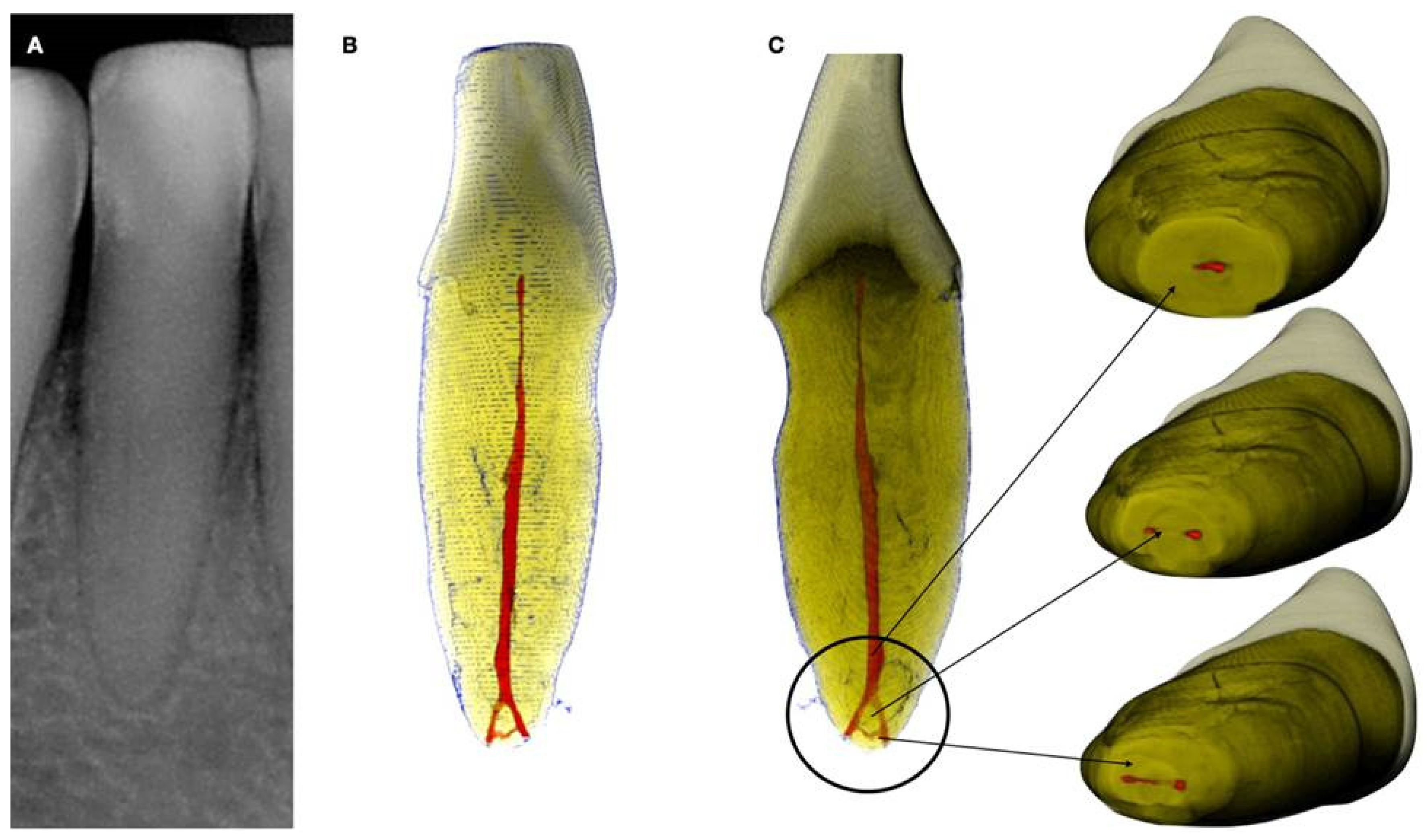
Figure 2.
Axial micro-ct slices of the calcified mandibular incisor of Figure 1 revealing the cross-sectional root canal dimensions along the root. The crown of the tooth is completely blocked, and the canal is visible starting at the level of the CEJ. The root canal dimensions are constricted in the coronal part of the root and become wider in the middle third of the root and splitting in the apical third into two canals. In calcified cases root canal dimensions usually present an inverted taper. (Skyscan 1172 micro-CT scanning device, Bruker MicroCT, Belgium). (Images courtesy of dr. Alexey Volokitin).
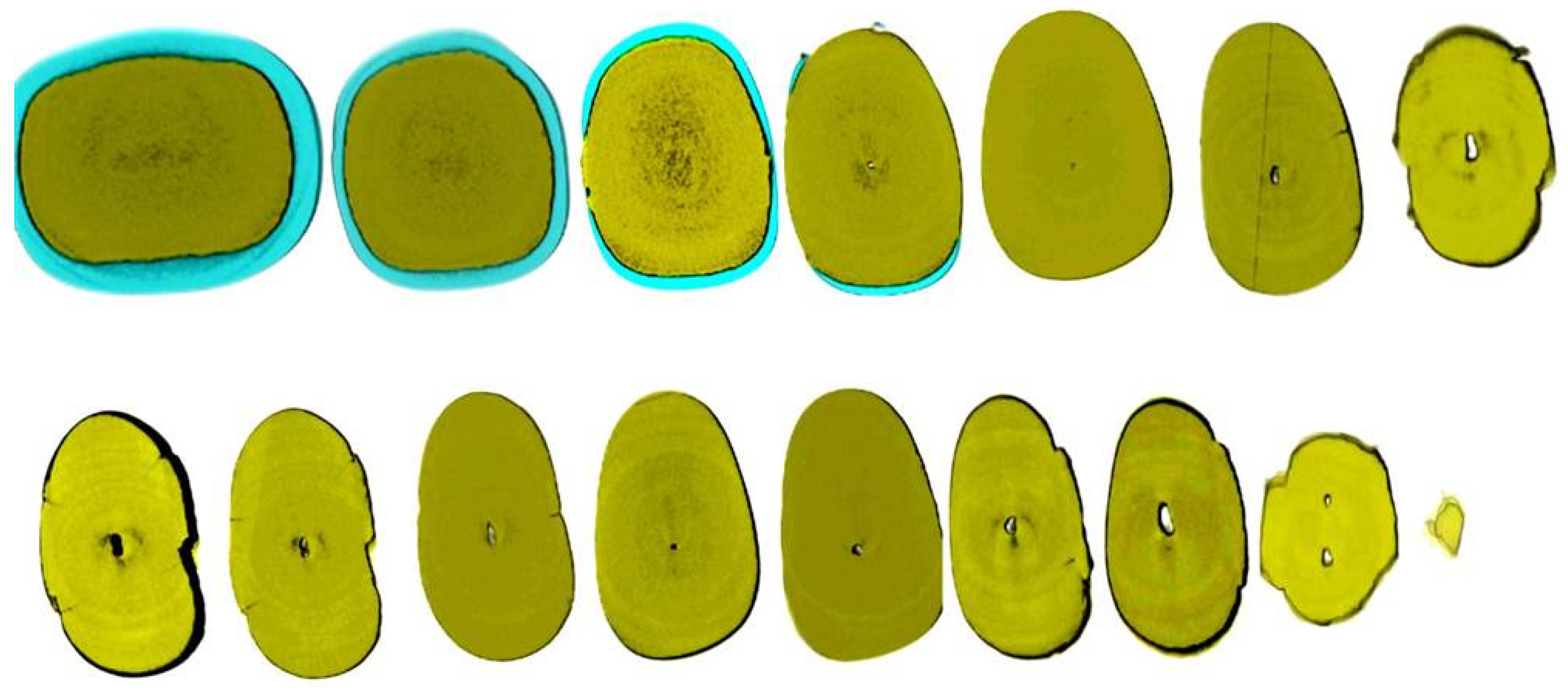
Figure 3.
Histological images of the calcified vital pulp tissue that was removed during the root canal treatment of a second mandibular molar with deep periodontal distal lesion suffering from symptomatic irreversible pulpitis. Notice the linear calcified nodules formed along the root pulp vessels. (hematoxylin eosin staining) (Histological images courtesy of prof. Domenico Ricucci).
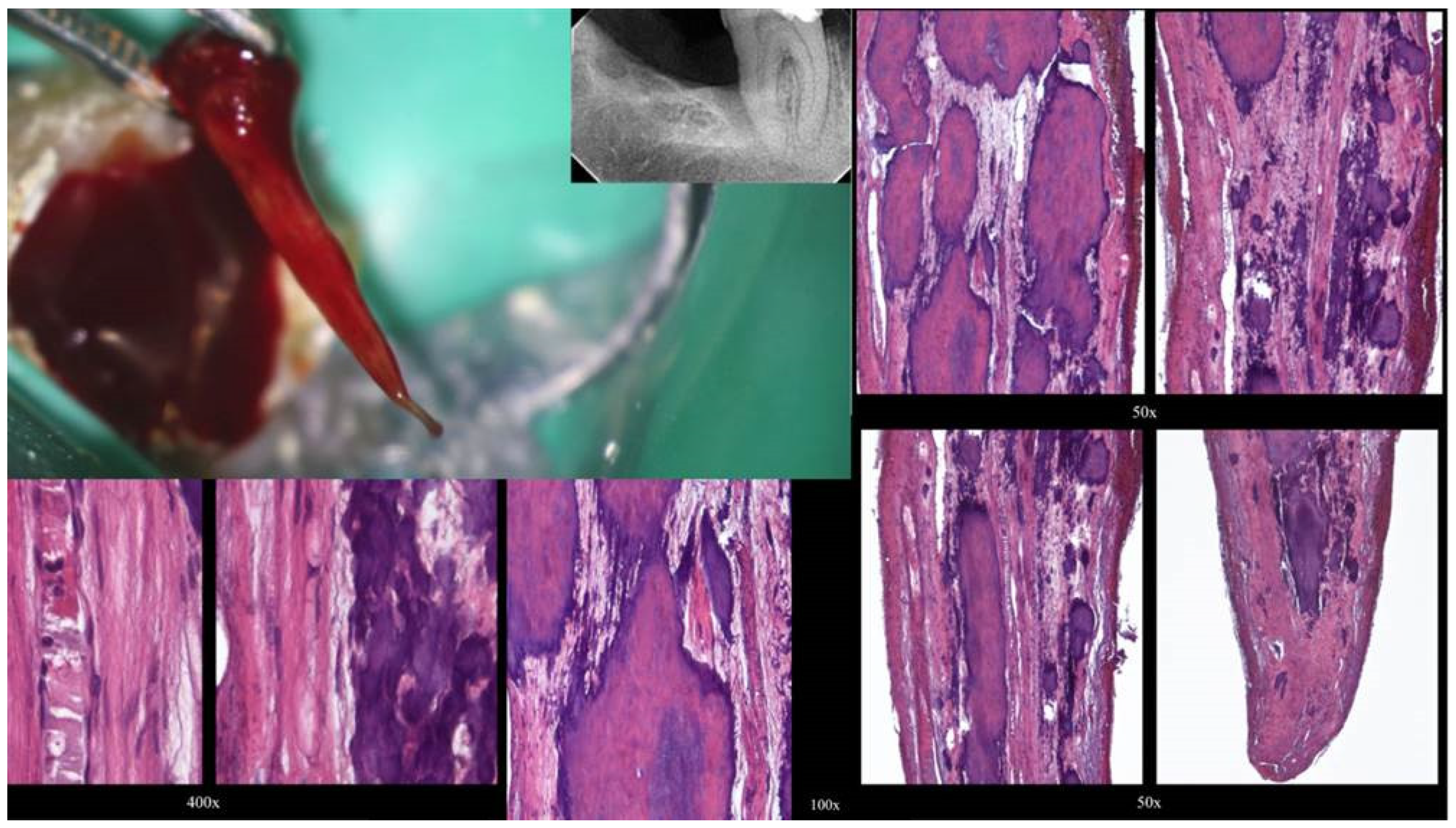
Figure 4.
Removal of a pulp stone from a second mandibular molar suffering from irreversible pulpitis. Micro-ct evaluation of the external and internal structure of the pulp stone. Notice that the structure of the pulp stone is not solid presenting an internal network of unmineralized tissue. The clinical significance is that the pulp stones can be dissected in smaller pieces and removed.
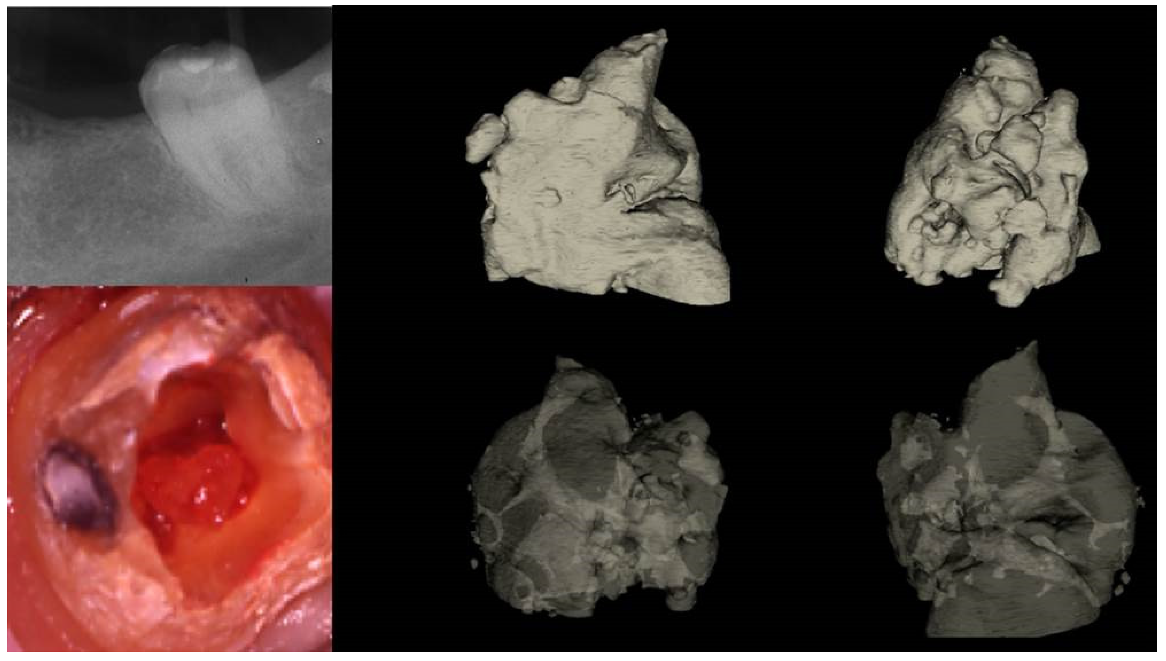
Figure 5.
The free pulp stone's histology shows distinct calcified nodules growing around a network of unmineralized extracellular matrix material and capillary vessels. (hematoxylin-eosin staining).
Figure 5.
The free pulp stone's histology shows distinct calcified nodules growing around a network of unmineralized extracellular matrix material and capillary vessels. (hematoxylin-eosin staining).
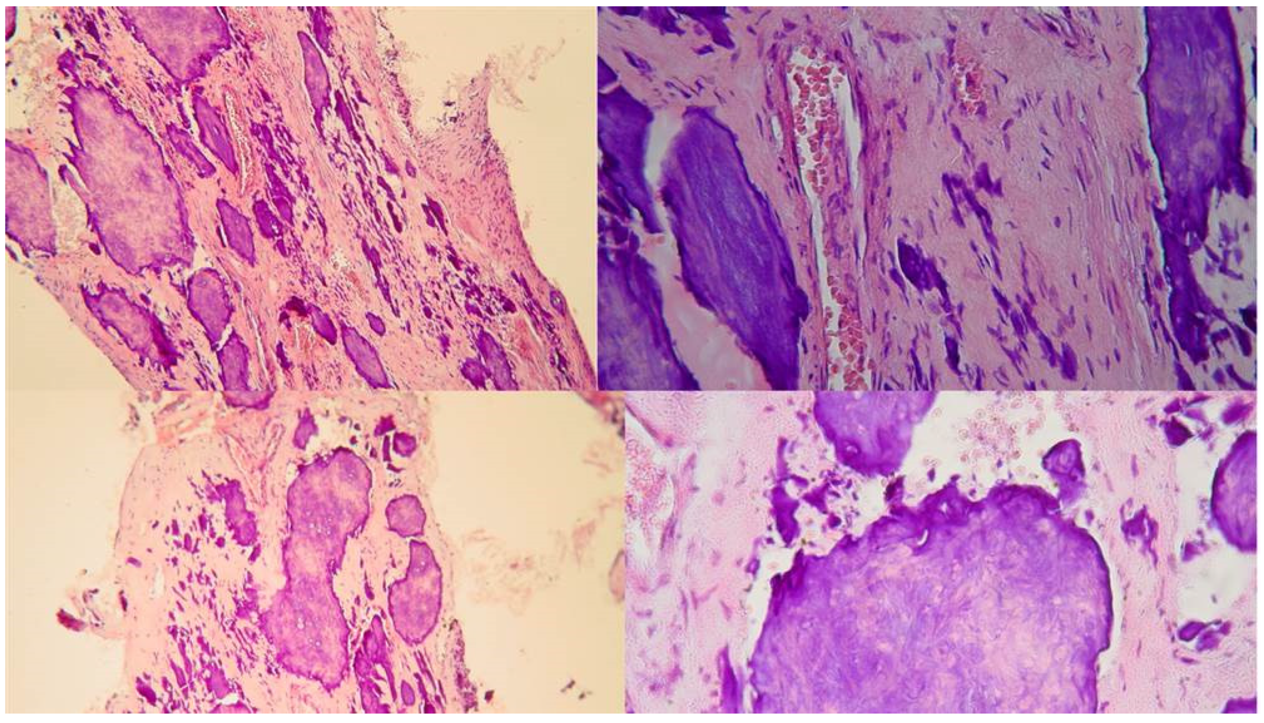
Figure 6.
a. Preoperative radiograph of a calcified lateral incisor that suffered a crown fracture. The root canal treatment negotiation was initiated but stopped because of the non-detectable canal and misorientation. The root canal is not visible in the radiograph, b. clinical view of the access cavity after cleaning the debris. The arrow points to a white spot indicating a possible canal, c. higher magnification clinical view. The peripherical dentine is yellow, followed by a central circular grey area that holds a white spot of accumulated debris in the white spot (black arrow), d. A D-finder file (Mani, Japan) negotiating the calcified canal (initial catch). The red circle indicates the arrested misoriented previous access, e. postoperative radiograph, f. Clinical view of the initial glide path file removing pieces of coronal restrictive dentin, g. Clinical view of the calcified canal after the shaping procedures. Transillumination reveals the radial orientation of the dentinal tubules. The reflection of the microscope light gives the characteristic butterfly effect impression (arrows), h. The clinical view of the gutta-percha cut deep inside the canal during post-space preparation.
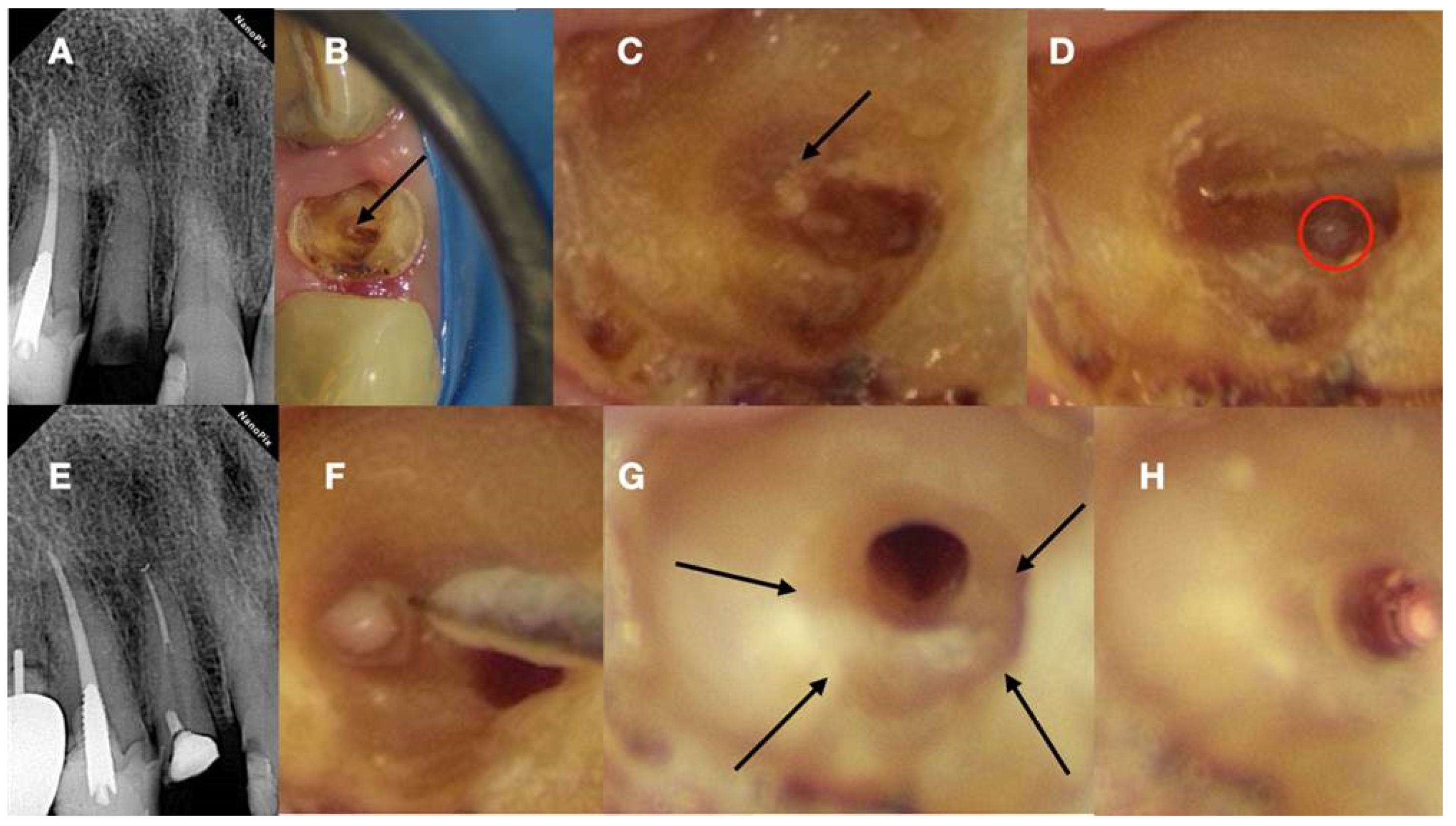
Figure 7.
a. Radiographic image of an extracted partially calcified maxillary premolar, b. microscopic view of the axial coronal cut through the calcified orifices of the extracted maxillary premolar, c. Magnified microscope view of the area in the square. Notice the circular deposits of calcified material in the periphery reflecting different stages of tertiary, reactionary, or reparative dentine formation. Concentric on these circular deposits, a grey area exists with a white spot of debris accumulation in the center. This white spot is indicative of the canal location.
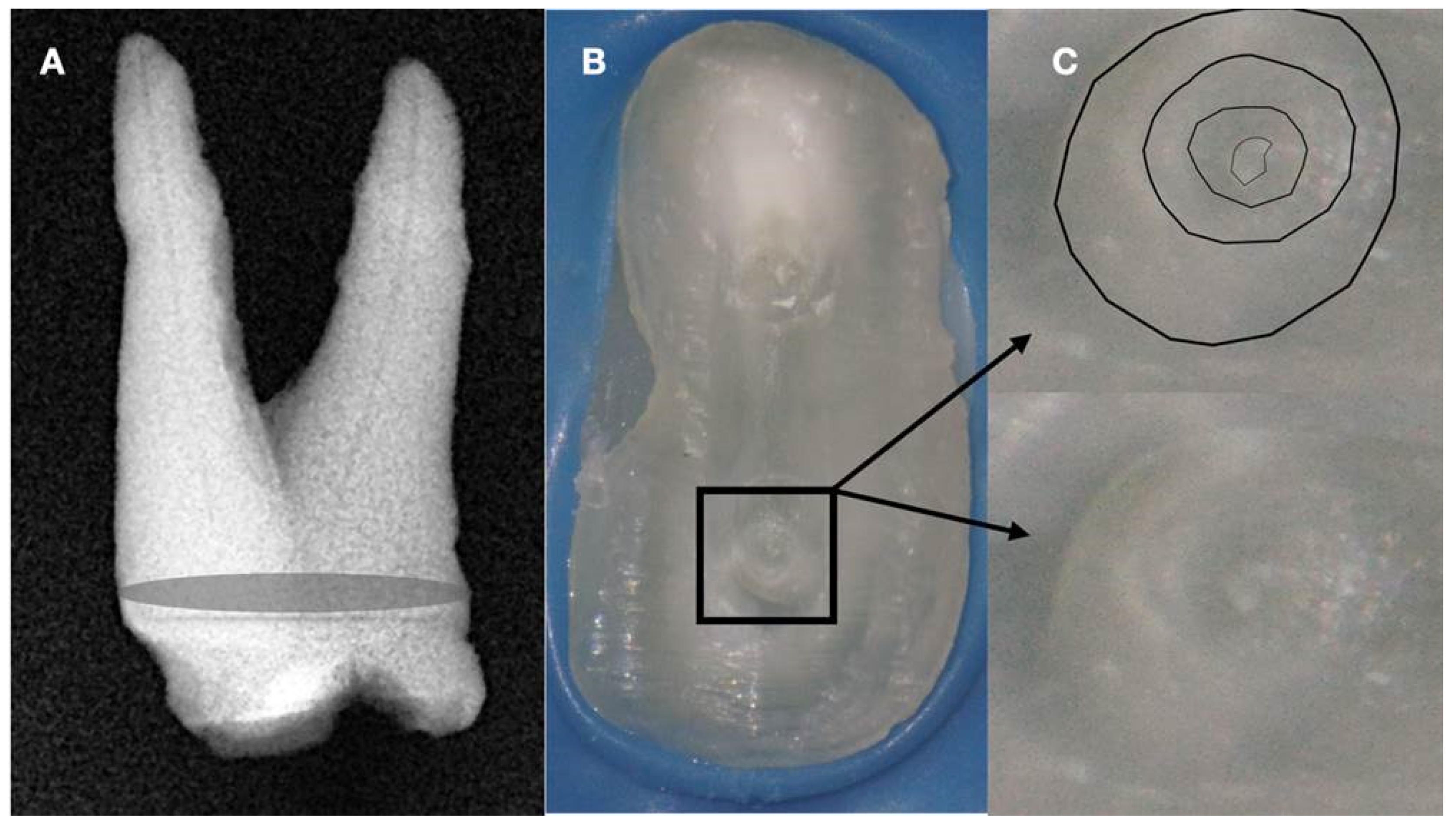
Figure 8.
a. Scanning Environmental Microscope image of the tip of a Grinded Niti file, b. Scanning Environmental Microscope image of the tip of an Electrical Discharge Machined Niti file. The EDM procedure creates a rough surface in the tip of the instrument making the tip active when activated and increasing the cutting efficiency of the file (Images courtesy of dr. Alexey Volokitin).
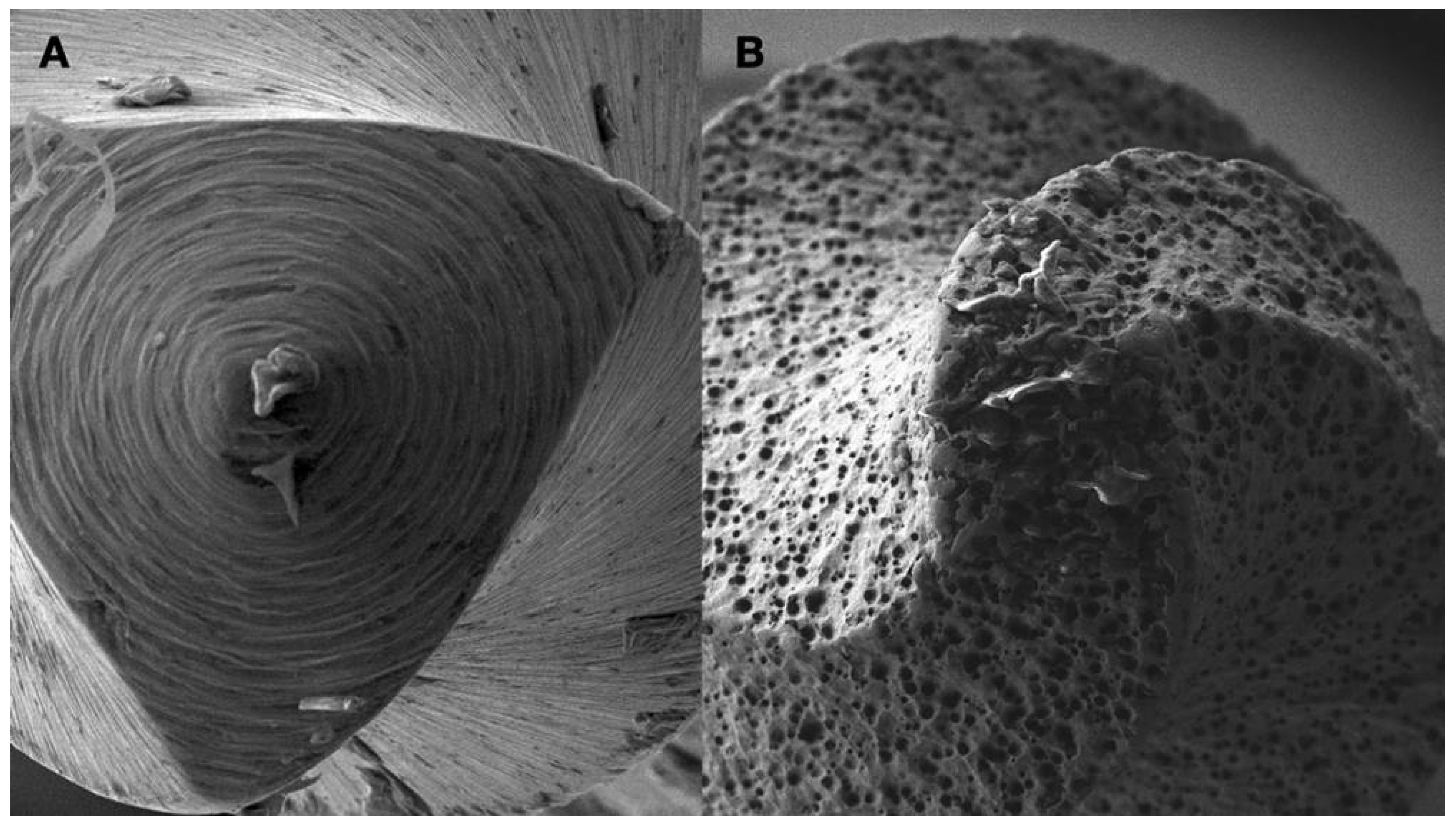
Figure 11.
(I) a. Pre-operative panorax focused in the impacted right maxillary canine revealing a large lesion, b. 2 years follow-up panorax after the surgical removal of the lesion revealing healing, c-d. periapical radiographs reveal recurrent disease 6 years after the surgical intervention. Notice that the maxillary canine was brought in occlusion with orthodontic treatment but the canal was rendered radiographically blocked, e-f. CBCT axial slices evaluating the magnitude of the periapical lesion and the root canal calcification of the maxillary canine. (II) a-b. Clinical microscopic image from two different angles of the previously initiated access cavities. Notice the gray spot indicating the calcified root canal orifice (yellow arrow), c. clinical image of the initial troughing of the calcified canal with a round long shafted bur (Munce Bur), d. EDM file during the Buckling Resistance Activation Test negotiation technique, e. clinical image of the calcified orifice after the first BRAT stroke. Canal negotiation with 08 D-finder file is now possible. (III) a. Pre-operative periapical radiograph, b. periapical radiograph demonstrating the initial negotiation of an 08 D-finder after the first BRAT stroke, c. periapical length determination radiograph, d. postoperative radiograph, e. 1 year follow up periapical radiograph, f-g-h. 3 years follow up cbct revealing complete healing of the periapical lesion (axial slices).
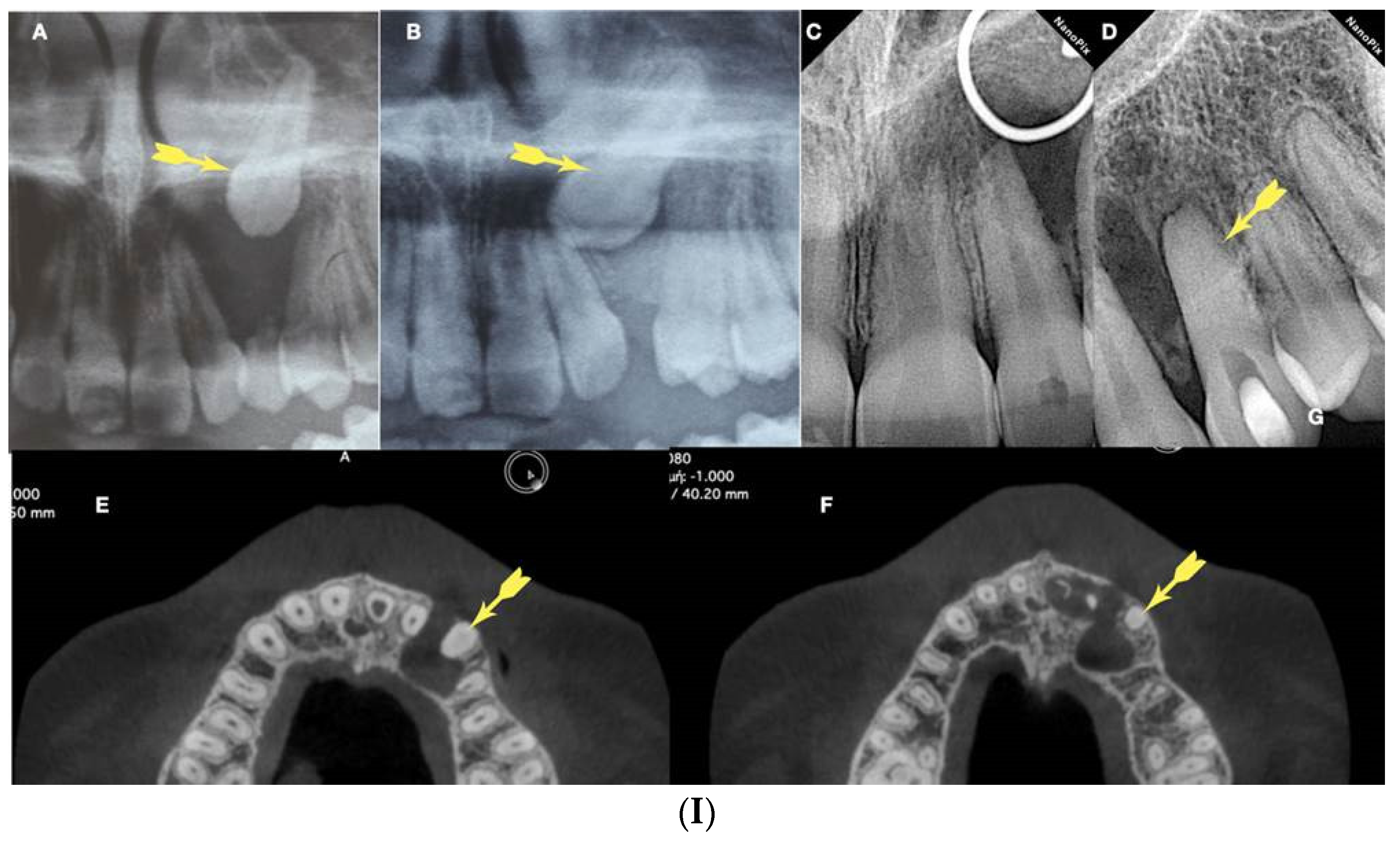
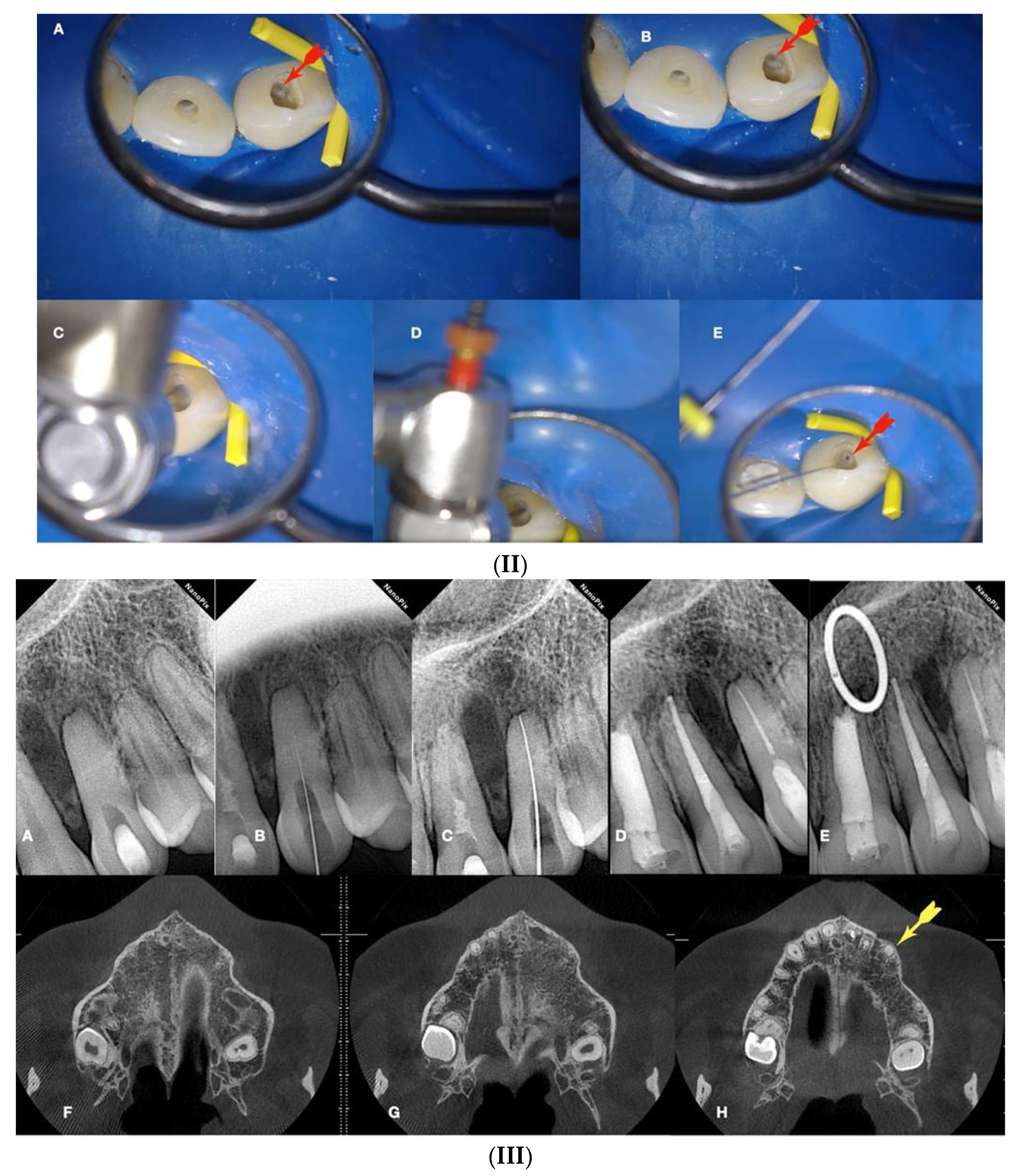
Figure 12.
Calcified maxillary molar negotiation a. Preoperative radiograph of the maxillary molar with no detectable canals, b. Clinical view of the access cavity revealing a completely calcified chamber, c. clinical view of the ultrasonic troughing of the pulp floor. Notice the pulp floor color is grey, d. clinical view of the axial wall floor junction developmental line (yellow arrow). The canal entrances in a maxillary molar always originate from this line, e, f & g. Clinical image of the shaped canals. Notice the location of the canals in a calcified maxillary molar is always lying along the wall-floor junction developmental lines, h. Postoperative radiograph of the calcified maxillary molar treatment.
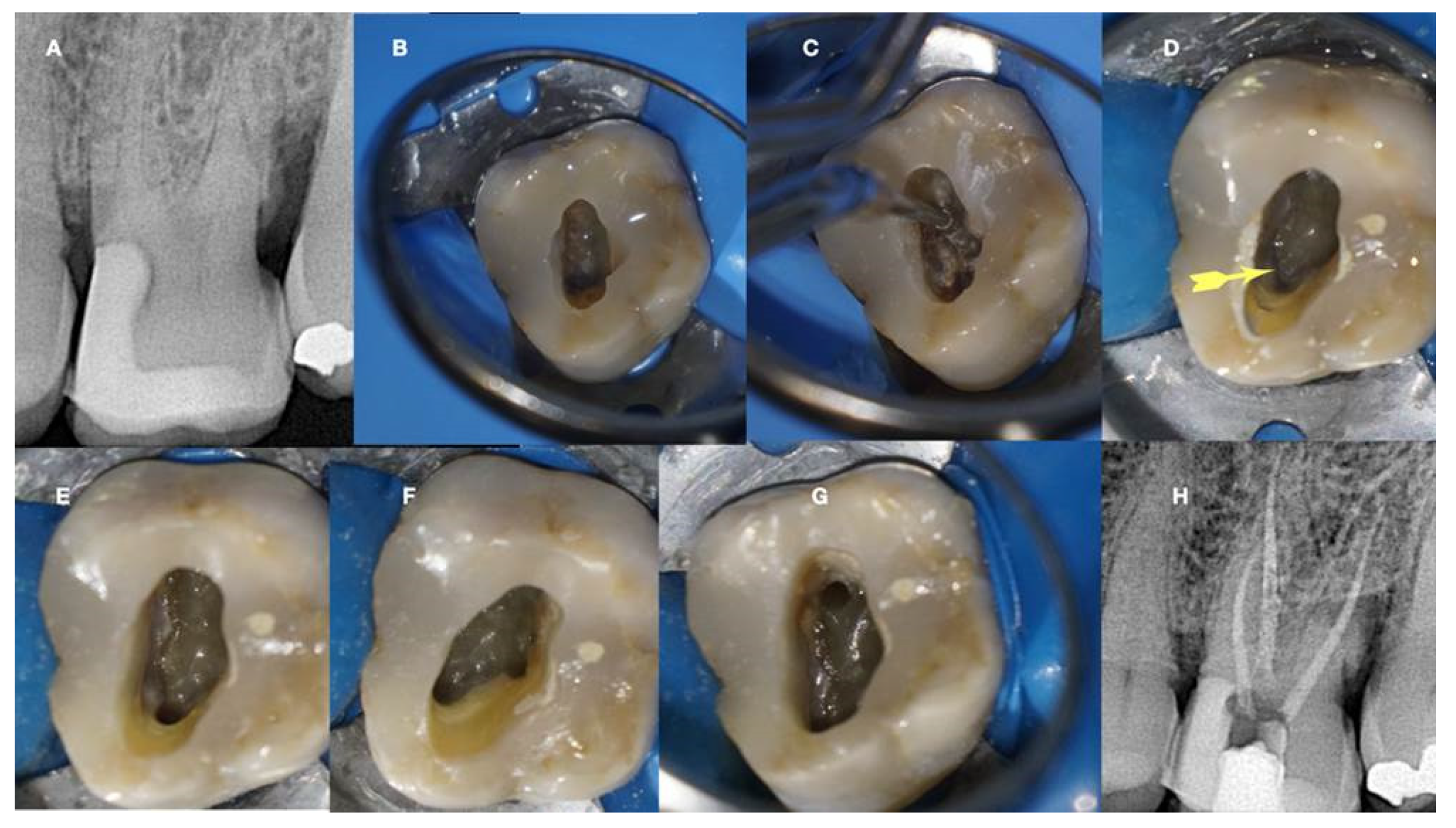
Figure 13.
Calcified mandibular molar negotiation a. Preoperative radiograph of a calcified mandibular molar with no visible canals, b. clinical view of the calcified chamber, c. clinical view of the calcified tissue blocking the access to the mesial canal system. Notice the white color of the calcification. The axial walls are yellow, and the pulp floor is always grey, d. clinical view of the pulp floor developmental lines after the removal of the white calcified tissue. Chasing the dark grey developmental lines to their termini will reveal the calcified canal entrances, e. Clinical view of the canals shaped, f. postoperative radiograph of the calcified mandibular molar canal treatment.
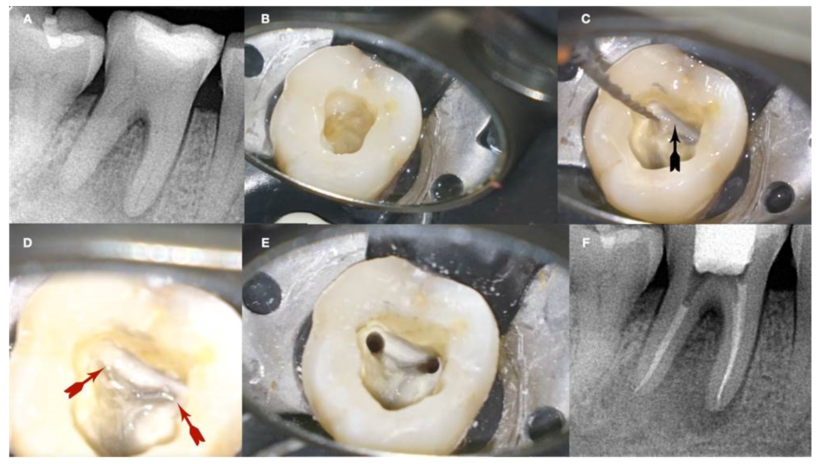
Figure 14.
Calcified maxillary premolar negotiation a. preoperative radiograph of a calcified maxillary premolar associated with apical periodontitis, b. clinical view of the palatal calcified canal orifice (red arrow), c. clinical view of the buccal calcified canal orifice after chasing the pulp floor developmental line to its far end (red arrow), d. clinical view of the EDM file buckling resistance activation test negotiation, e & f. clinical and radiographic image of the calcified canal negotiation, g. post-operative radiograph of the calcified maxillary premolar treatment.
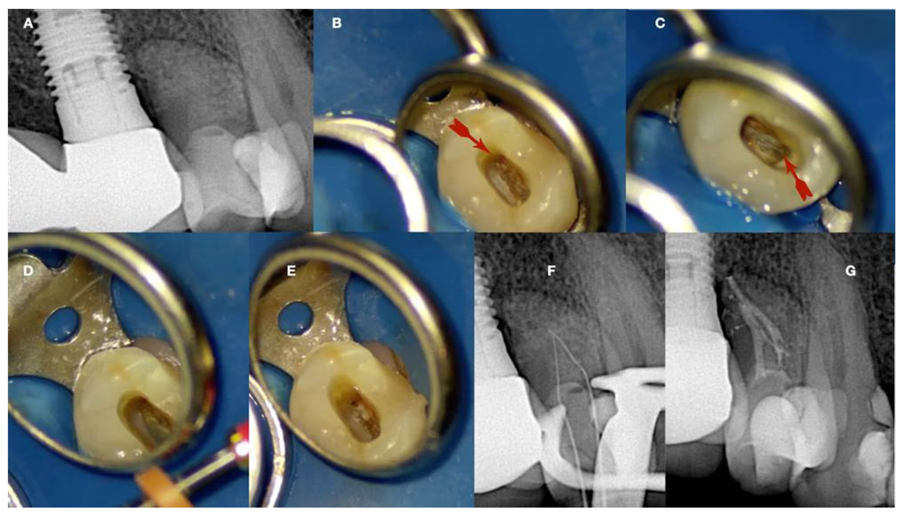
Figure 15.
(I) a. Preoperative periapical radiograph of calcified maxillary central incisor diagnoses with apical periodontitis, b. Preoperative clinical buccal view of the maxillary central incisors, c. Preoperative cbct scanning of the maxilla, d. preoperative intraoral scanning of the maxilla, e. Matching the CBCT scanning with the intraoral scanning and designing the guide in the codiagnostiX software. (II)a. 3d printed surgical guide with lateral windows to check the adaptation, b. intraoral fitting of the surgical guide, c-d. pencil marking of the access location point lingual and buccal view, e. Access point mark to remove the enamel, f. fitting of the surgical guide and drilling the initial pilot hole, g. Clinical palatal view of the guided access, h. intraoperative radiograph of the pilot drill (Steko bur), j-i. length determination and gutta-percha fitting radiographs, k. Postoperative radiograph, l. 2 year follow up radiograph reveals healing.
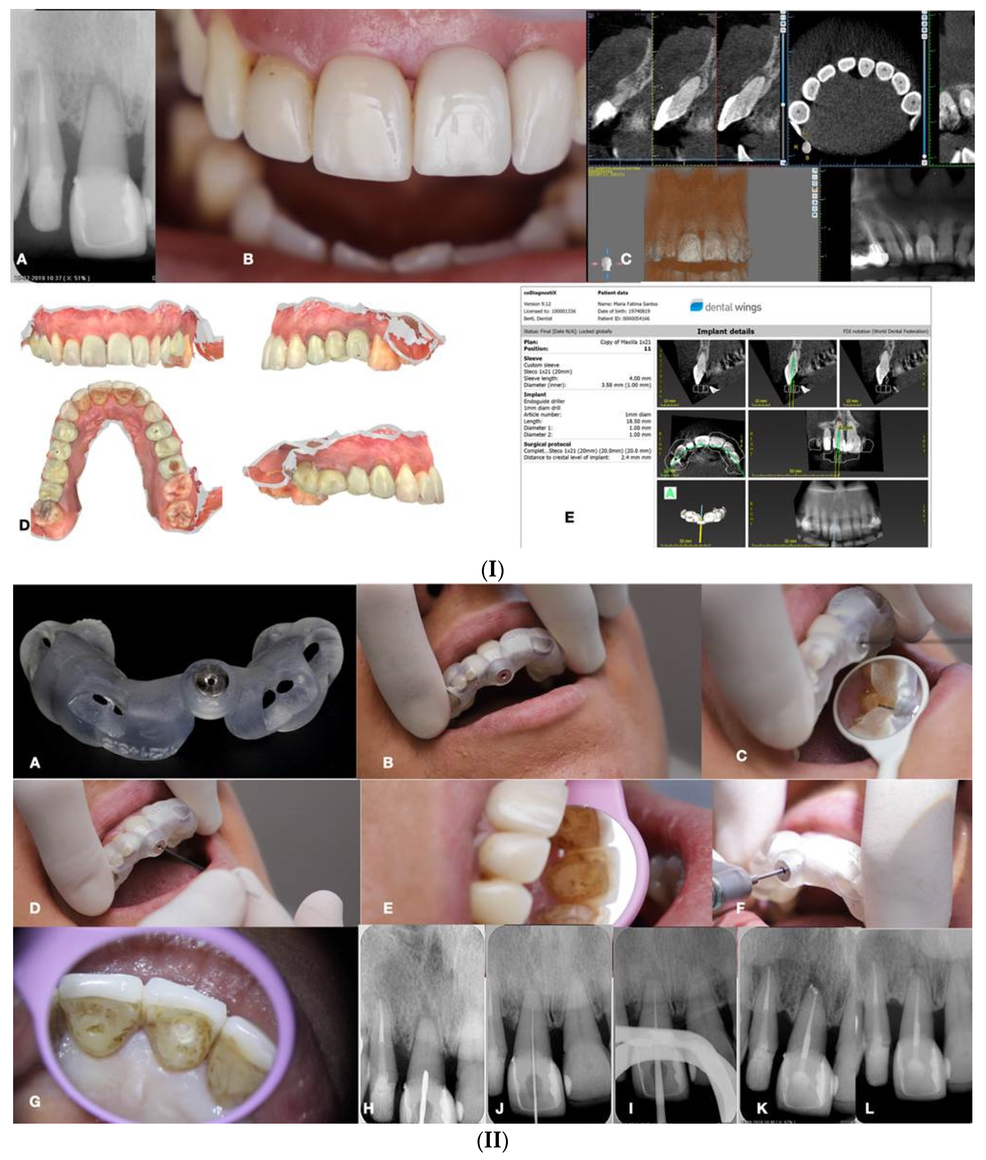
Disclaimer/Publisher’s Note: The statements, opinions and data contained in all publications are solely those of the individual author(s) and contributor(s) and not of MDPI and/or the editor(s). MDPI and/or the editor(s) disclaim responsibility for any injury to people or property resulting from any ideas, methods, instructions or products referred to in the content. |
© 2024 by the authors. Licensee MDPI, Basel, Switzerland. This article is an open access article distributed under the terms and conditions of the Creative Commons Attribution (CC BY) license (http://creativecommons.org/licenses/by/4.0/).
Copyright: This open access article is published under a Creative Commons CC BY 4.0 license, which permit the free download, distribution, and reuse, provided that the author and preprint are cited in any reuse.


