Submitted:
15 March 2024
Posted:
15 March 2024
You are already at the latest version
Abstract
A self-propelled electric tea seed-planter is designed to address the lack of tea seed seeding equipment, low seeding efficiency, and poor seeding uniformity. Based on the physical characteristics of the tea seeds and the agronomic requirements of tea planting, the key structure of the planter is designed, and the structural parameters are determined. The motor and battery configurations are determined by calculating the power consumption of the entire machine. In a field experiment, the driving gear (A), ditching depth (B), and planting gear position (C) are used as test factors, and the acceptance index (AI), replay index (RI) and leakage index (LI) are used as test indexes. The test results showed that the driving speed and planting gear position significantly affect the acceptance index, replay, and leakage index, whereas the ditching depth has little effect on the performance indexes. When the driving speed was medium, ditching depth was 30 mm, and planting gear position was in the third gear, the corresponding acceptance index was 87.22%, the replay index was 8.89%, and the leakage index was 3.89%. The test prototype has a good working quality and can provide theoretical guidance for production practices.
Keywords:
tea seed
; electric
; planter
; orthogonal test
0. Introduction
Tea is one of the three major drinks consumed worldwide. Approximately 71.4 percent of the world’s countries and regions and approximately a third of its population drink tea. Tea was originally produced in China and has been grown and drunk for more than 5,000 years. Tea cultivation is mainly distributed in tropical and subtropical regions worldwide, with a tea cultivation area of 3.165 million hectares in China accounting for 62.1% of the total tea cultivation area in the world, ranking first in terms of tea cultivation [1]. According to a report by the General Station of Agricultural Mechanization of China's Ministry of Agriculture and Rural Affairs, in 2021, the tea garden cultivation, fertilization, plant protection, pruning, harvesting, and field transport mechanization rates were 22%, 11%, 35%, 43%, 35%, and 36%, respectively. The comprehensive mechanization rate is approximately 31.15%. Each link mechanization level is not high, and tea production mechanization will be the means by which China’s tea industry develops. However, we believe that this statistical analysis misses the most important link in tea production: mechanized planting. Mechanized planting is not only related to intertillage, fertilization, plant protection, pruning, harvesting, and field transfer; mechanized tea garden operations can also result in smooth development and directly affect the quality and yield of tea. Hence, mechanized tea planting (including breeding and transplanting) is the key component of mechanized tea production.
Tea breeding methods include sexual, asexual, and transgenic cultivation. Sexual propagation uses seeds to propagate tea seedlings. Tea seedlings have deep soil, well-developed taproots, high survival rates, and strong drought and cold resistance [2]. Sexual reproduction can result in greater genetic variation, which is critical for the cultivation of improved tea varieties. Asexual propagation is mainly conducted via cutting, which is widely used in the large-scale breeding of fine tea varieties to realize the rapid promotion and planting of superior varieties; however, asexual propagation faces the problem of rapid loss of some gene sources that have not been recognized and used [3]. Transgenic cultivation has been used to improve tea trees, tea yield, and insect resistance via genetic engineering. Currently, this technology is still in the development and research stages, and its commercial application faces many controversies and challenges [4]. Based on a comparison of the results of the above three methods, some scholars believe that the cultivation of improved tea varieties mainly depends on sexual reproduction [5], that is, using tea seeds to sow and raise seedlings. Currently, tea seedlings are mainly artificial and lack devices that meet the requirements of tea seed planting agronomy, leading to low work efficiency, high labor costs, and a lack of sowing uniformity. Hence, research and development are required for tea sowing machinery, improving tea seed planting efficiency and sowing quality, reducing the labor intensity of tea seed sowing, and improving production.
Many scholars have conducted in-depth research on sowing devices and developed practical sowing machinery [6,7,8]. Based on the shape characteristics of garlic, Wenyuan [9] developed a hole-wheel garlic seeder. A field test showed that it had a good seeding effect, with a qualified rate of 88.44%, a missing sowing index of 7.44%, and a replay index of 4.11%. Zolha et al. [10] studied the influence of different operational parameters on maize-seeding devices. The study showed that the hole shape, peripheral velocity, vacuum pressure, and hole area had significant effects on seeding. The optimal shape of the seed hole was rectangular, the seed holding rate decreased with an increase in the velocity around the seed plate, and the seed holding rate increased with an increase in vacuum pressure. Ozherelyev et al. [11] analyzed the causes of the spatial orientation instability of potato tubers during seed selection using dynamic theory and optimized a prototype, achieving a qualified potato tuber orientation rate of more than 97%. Liao Yitao et al. [12] analyzed the seed discharge process of a seed discharge device by combining a theoretical analysis with high-speed camera technology, identified the factors affecting the seed discharge track of the device, and provided a basis to optimize the structural design of the device. Yoxia [13] and Mengmeng [14] studied the effect of vibration on seeding performance from the vibration direction, and the results showed that the replay rate tended to decrease and that the missed sowing rate tended to increase with an increase in vibration frequency and vibration amplitude. Other scholars [15,16,17] studied the seed spoon of a seeder using discrete element simulation and response surface optimization methods to obtain better structural parameters for the seed spoon and improve the seeding effect of the seeder. Lu Yao et al. [18] adopted an orthogonal test method to analyze the effects of the advance speed, seed-casting angle, and seed-casting height of a corn planter on seeding performance and obtained a better parameter range. The field experiment showed that the qualified seed spacing rate was greater than 95%, the single-seed rate was greater than 90%, and the hole rate was less than 5%.
Based on the research conclusions and methods of the above scholars, we designed a self-propelled electric tea seed seeder by combining the physical and mechanical characteristics of tea seeds and planting agronomy and carrying out corresponding tests. Through experimental optimization methods, we expect to obtain better operation parameters of the seeder, achieve a better seeding effect, and promote the development of mechanized tea seeding planting technology.
1. Materials and Methods
1.1. Measurement of the Physical Parameters of Tea Seeds
Seed size, shape, weight, and surface characteristics have important effects on the performance of the seeder. Therefore, we conducted research on the physical and mechanical characteristics of tea seeds.
1.1.1. Size Measurement of Tea Seed
The shapes and sizes of tea seeds have a significant influence on the filling of the seed spoon and the fluidity of the seeds in the seed box. Therefore, it is necessary to determine the size and shape characteristics of tea seeds. Under normal circumstances, the surface of a tea seed is smooth, and the shaped structure can almost be regarded as an ellipsoid. We used a wide diameter La and a long diameter Lb to describe the outline sizes of the seeds, as shown in Figure 1 (a) and Figure 1 (b).
To understand the shape and size distributions of tea seeds, two different tea seeds (Normal 1 and Extra Early 1) were selected, and 400 seeds were randomly sampled and measured with a Vernier caliper (range of 300 mm, precision of 0.02 mm). Figure 2 show a histogram of the size frequency distribution. From the perspective of the major diameter size distribution, the size of Normal 1 was mainly distributed in the range of 10–17 mm, and the size of Extra Early 1 was mainly distributed in the range of 10–16 mm. Both were myopically normal distributions. From the perspective of the broad diameter size distribution, the normal 1 broad diameter size was mainly distributed in the range of 11–17 mm, and the broad diameter size of Extra Early 1 was mainly distributed in the range of 10–16 mm. Again, both were myopic normal distributions. In summary, more than 90% of the major and broad diameters of the two types of tea seeds were distributed in the range of 10–16 mm.
1.1.2. Hundred Grain Weight and Water Content Measurement
The seed weight had some influence on the stability of the charging and seed carriage of the seed arrangement device. For example, for a chain-spoon-type seed distributor, the seed weight is too low, and the instability of the filling and carrying processes increases, which reduces the sowing accuracy. For Normal 1 and Extra Early 1, 100 tea seeds were randomly selected, and the tea seeds were weighed using an electronic scale (LD510-2, accuracy of 0.01 g, Shenyang Longteng Electronics Co., Ltd.). The corresponding weights were recorded five times. The average hundred grain weight of Normal 1 was 105.52 g, and that of Extra Early 1 was 108.73 g.
The seed moisture content is an important indicator of seed quality. Seed is not easy to store with a high moisture content, as the adhesion between seeds becomes large, which affects the seeding accuracy of the seed discharging device. When the moisture content of the seeds is too low, the physiological activity of seeds will be affected. In this study, the constant temperature drying method was used to determine the water content specified by the national standard GB5009.3-2016 "Determination of Water in National Standard of Food Safety.” A drying oven (HD-E804-60A, accuracy of ±0.1 ℃, Haida International Instrument Co., Ltd.) was used to bake the two types of tea seeds (5 parts each), and the weight before and after baking was measured using an electronic scale. The water content of each sample was calculated using the formula. After taking the average value, the water content of the Normal 1 tea seeds was 17.38%, and that of the Extra Early 1 tea seeds was 15.47%, which met the commonly used water content requirements for seed storage [19].
1.2. Structure and Key Components
Combining the physical and mechanical characteristic parameters of tea seeds and the agronomic requirements of tea planting, we designed a self-propelled electric tea seed planter and expounded the working principle of the tea seed planter.
1.2.1. Structure and Principle
A self-propelled electric tea seed planter is primarily composed of frames, ditchers, seeding devices, shifters, drive wheels, seed boxes, press wheels, DC motors, and rechargeable batteries, as shown in Figure 3. The seed box, seeding device, and ditcher were assembled into a single body to form a trenching-seeding unit.
When preparing for seeding, the shifter is adjusted from the neutral position to the forward gear, the walking switch on the control box is dialed, and power is started and delivered to the driving wheel through the chain to drive the entire machine to walk. As the seed planter is walked, the ditcher marks the seed ditch at the same depth on the ridge surface, and the seeding device drives tea seeds out of the seed box via another transmission branch to accurately put them into the seed ditch. Then, soil particles are backfilled to the seed ditch under the action of the soil-covering rod to cover the seeds. Finally, soil suppression is completed by the suppression wheel. During operation, the machine can simultaneously achieve ditch opening, sowing, and suppression at one time. While completing the operation, the shifter is adjusted to a neutral position to cut off the driving power to ensure that the machine does not sow.
The overall parameters of the self-propelled electric tea seed planter, according to the agronomic requirements of tea seed sowing, are listed in Table 1.
1.2.3. Structure of Seeding Device
The chain-spoon-type precision seeding device used in this study is a single-row monomer-type seeding device that includes an active sprocket, auxiliary sprocket, chain, seed spoon, seeding sprocket, and seed-protection shell, as shown in Figure 4. Combined with the size distribution area of the tea seeds, the seed spoon was selected from existing market products. The major diameter of the seed spoon hole was 20 mm, the broad diameter was 16 mm, and the depth was 6 mm, which ensured that the seed-filling process of the seed spoon hole could contain only one tea seed. The seed trap can be divided into four areas, namely, the filling, clearing, seed protection, and casting areas, among which the filling area is located in the seed box. While the seeding device is operating, power is input by the active sprocket, which drives the chain to rotate clockwise. As the seed spoon goes into the filling area, the seeds fall into the seed spoon to complete the filling under the weight of the seeds and inter-seed forces. As the chain continues to rotate, the seed spoon will leave the filling area and enter the clearing area. Redundant seeds that may exist in the seed spoon will leave the seed spoon under the action of gravity and chain vibration so as to ensure that only a single seed is retained in the seed spoon. The seed spoon continues to move upward with the chain, and when it passes the highest point of the active sprocket, the seed breaks away from the seed spoon type hole and falls on the bottom of the previous seed spoon under the action of gravity and centrifugal force to enter the seed protecting area. In the seed protecting area, the seeds stay in an independent space formed by the two seed spoons and the seed protection shell. Then, they enter the seed casting area with the movement of the chain. In the casting area, when the sliding force of the seed is greater than the maximum static friction force, the seed slides away from the bottom of the seed spoon and falls into the seed ditch to achieve seeding. Then, the spoon turns around the sprocket and re-enters the filling area, thereby entering the next cycle to continue to complete the seeding operation.
1.2.4. Structure of the Ditcher
A double-disc ditcher was used in the study. As a key component of the planter [20], its structure mainly includes columns, baffles, disks, and bearing-end covers, as shown in Figure 5. The two disks at the front end of the ditcher intersect at the convergence point m. The angle between the convergence point position and the plumb weight direction is β, and the angle between the two disks is ∅, as shown in Figure 6. According to [21], the following relationship is satisfied among the parameters:
where
b=trench width (mm),
R=disc radius (mm).
According to the above formula, the trench width increases with an increase in the diameter and angle of the disk. For the double-disc ditcher, a large trench width can easily cause an increase in the middle bulge of the groove, which adversely affects seeding. Additionally, the common double-disc angle ∅ is 9–16°. The higher the location of the convergence point, the more the angle β and the width of the trench will increase, meaning that the high location of the convergence point will cause the width of the trench to be larger. In the actual selection, the value of β ranged from 55° to 75°. In the design, the diameter of the disc, selection of the convergence point, and size of the angle between the two discs should be determined according to the agronomic requirements of the actual sowing.
According to the agronomic requirements of tea seed sowing, the sowing depth should be 30–50 mm [22]. We chose a double-disc with a diameter of 200 mm. According to Equation (2), the disc radius is greater than the maximum trench depth, which satisfies the design requirements. The calculated results show that the angle β of the convergence point position is 67.97°. Finally, β is rounded to 68°.
where
hmax = Maximum trench depth (mm).
Considering that ditching quality has a significant influence on tea seed sowing, the ditching width of a double-disc ditcher should not be too large [23]. To ensure that the tea seeds fall smoothly into the seed ditch, the opening width should be greater than the seed size limit, as shown in Equation (3):
where
Smax= Limit size of tea seeds.
We take Smax=16mm. According to Equation (3), the angle between the two disks must satisfy ∅ > 14.70°. Finally, ∅ is rounded to 15°. Furthermore, according to Equation (1), the trench width b was 16.3 mm.
1.2.5. Design of Transmission System
Unlike other types of seed planters [24,25],the tea seed planter in this study was driven by a motor. The entire transmission system can be roughly divided into the power, driving, and seeding systems, as shown in Figure 7. The transmission of motion between systems is realized through a chain transmission.
Considering the different needs of seeding spacing, a special six-speed governor of the planter produced by the Pengfeng Company was set in the seeding system. The input gear teeth of the governor are 18, and the output teeth are 15, 18, 21, 24, 27, and 30. The corresponding six gear transmission ratios are 0.833, 1, 1.167, 1.134, 1.5, and 1.667, respectively. During the design, the driving system and the seeding system are driven by the same power system, and the transmission ratio of the driving system and the seeding system are calculated to simultaneously obtain the driving distance of the driving wheel and the number of spoons involved in the seeding. The sowing distance under different gear positions can be obtained by comparing the two values, as shown in Table 2.
1.2.6. Power Calculation and Battery Selection
- (1)
- Power calculation
The operation process of a tea seed planter must overcome trenching, driving, soil covering, and transmission friction resistances. In this process, the power consumed to overcome the trench and driving resistances accounts for more than 80% of the total power consumption of the system. The power consumption of the system satisfies the following relationship
where P is the total power, Pq is the trench power consumption, Pt is the forward driving power consumption, Pp is the power consumption of the soil cover, and Pf is the transmission friction power consumption. Considering that the soil cover and transmission friction resistances were small, the driving power consumption of the trenching power and driving power consumption were analyzed empirically in the power calculation.
During the ditching operation, the power consumption of the double-disc ditcher mainly originates from the disc cutting soil and disc throwing soil [26]. Its power consumption satisfies the requirements shown in Equation 5. Moreover, the trench tray of the tea seed planter is rotated passively while driving, the maximum speed of the tray does not exceed 100 r/min, and the soil throwing effect of the disc is weak. Therefore, the trench operation mainly considers the power consumption of the tray-cutting soil.
where
Pqx = cutting soil power consumption (kW),
Pqp=Disc throwing power consumption (kW),
k = cut specific resistance (kN/m2),
b = trench width (mm),
h = trenching depth (mm),
v = planter forward speed (m/s).
According to the relevant scholars’ research [26], we take k = 137 kN / m2, b =16.3 mm, and h =50 mm. The maximum speed of the seeder driving forward is assumed to be v =1 m/s. The power consumption of a single trench opener of the tea seed planter is 0.11 kW, and the total power consumption of the trench opener is 0.44 kW.
Rolling resistance is the main source of power consumption during planter operation. The forward power consumption of the entire machine satisfies the following relationship:
where f is the rolling friction factor; m is the machine weight (kg); and v is the forward speed of the seeder (m/s).
The soil resistance in a tea garden is relatively large, the rolling friction factor is set to 0.4. The weight of the whole machine is 95 kg, and the maximum forward speed of the seeder is 1 m/s, meaning that the forward power consumption of the whole machine is 0.38 kW.
Considering that power consumption, accounting for the transmission friction and soil covering resistance of the seeder, accounts for approximately 20% of the total power consumption, the total amount of power required by the tea seed planter is 1.02 kW (Equation (7)). Considering the possibilities of an uneven ground surface and a large soil viscosity during the operation process, and given a power reserve coefficient of 1.5, the resulting total design power is 1.53 kW. Based on these calculations, we chose a brushless DC motor produced by the Taili Company of Sanmen County to provide power with a rated voltage of 24 V, maximum output power of 1.5 kW, and rated speed of 1800 r/min. Furthermore, the reduction ratio of the reducer that is directly connected to the output end of the motor is 1:60.
/0.8=1.02 kW.
- (2)
- Battery selection
Based on the cost, battery density, and environmental adaptability, seven lead batteries (Produced in series (24 V) by Dongguan Youneng Optoelectronics Co., Ltd.) were used as power sources for the tea seed planter. Assuming that the seeder works at the rated speed of the motor, the seeder will carry out seeding at a driving speed of 0.15 m/s. Its power consumption is calculated as 0.15 kW, according to Equations (4)–(7). For the DC motor, the required driving motor current I= 6.25 A was obtained. Assuming that the planter operates for 6 h per day, the required capacity for the battery is:
Considering that tea seed sowing is mostly carried out in autumn and winter, the outdoor temperature is low at this time, which has an impact on the battery capacity consumption. Therefore, the battery capacity consumption needs to be corrected [27]:
where
Qx = Fixed battery capacity consumption (Ah),
I= Maximum discharge current (A),
T = Total discharge time,
ƞ = Modified battery capacity,
t = Actual temperature (℃).
We set I = 5 A, T = 6 h, ƞ = 0.917, and t =10 ℃. By inserting these parameters into the formula, we obtain Qx = 46.47 Ah, which is less than the total battery capacity of 50 Ah. This indicates that the selected lead battery can satisfy the requirements of the sowing work under these temperature conditions.
1.3. Test Equipment and Materials
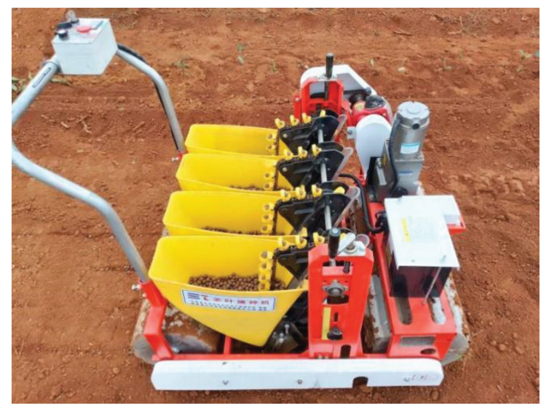
The test equipment includes a self-developed seed planter, soil moisture measuring instrument (Model: TZS-I, Zhejiang Topu Instrument Co., Ltd., Zhejiang, China; measuring range of 0–99.9%; accuracy of ±2%), ruler (Guangzhou Qiyike Industrial Development Co., Ltd., Guangzhou, China; measuring range of 0–500 mm; accuracy of 1 mm), steel measuring tape (Ningbo Great Wall Seiko Industrial Co., Ltd., Zhejiang, China; measuring range of 0–100 m, accuracy of 1 mm). The test site was located in the “Tea Full Mechanization Research Base” of the Xiangcheng Town Ministry of Agriculture and Rural Affairs, Gao'an City, Jiangxi Province. The average soil moisture content was 22.43%.
Figure 8.
Tea seed planter and test site.
1.4. Evaluation Index and Experimental Design
1.4.1. Evaluation Index
Based on the standard GB/T 6973-2005 “Test Method for Single Seed (Precision) Planter” [28] and the test outline DG/T 007-2019 “Planter” [29], the experimental research was carried out, and the acceptance index (AI), replay index (RI), and leakage index (LI) were taken as the evaluation indexes of the economy, reliability, and adaptability. The corresponding indexes are calculated as follows:
where
is the frequency of grain (hole) distance in each section,
is the frequency of grain (hole) distance,
Xi is a segment variable with a segment length of 0.1Xr,
xi is the median value of the section (mm),
Xr is the theoretical particle (hole) distance (mm),
N is the total number of particles (holes) determined by the test,
N’ is the number of intervals.
1.4.2. Experimental Design
Through a preliminary experiment, it was found that the operational stability of the entire machine is different under different driving gears. A high driving speed reduces the stability but increases the vibration of the whole machine, and a low driving speed reduces the seeding efficiency. Therefore, we consider the driving gear (A) as an influencing factor at low, medium, and high speeds. As an area of direct contact with the seeds, the seed trench may have an effect on the sowing. Considering that the sowing depth of tea seeds is 30–50 mm, the ditching depth (B) is also an influencing factor, and three ditching depths of 30 mm, 40 mm, and 50 mm were selected. The higher the gear, the faster the speed of the seeding. The planting gear position (C) was also considered as an influencing factor, and three gear levels (1, 3, and 5) were selected for the experiment.
To explore the influence of each factor on the sowing effect and obtain an ideal combination of test parameters, three-factor and three-level orthogonal test methods were adopted and applied to the L9(34) orthogonal table design test to analyze the impacts of multiple parameter changes on the performance of the seeder to provide a technical basis for the next promotion. The test factor levels are listed in Table 3.
2. Results
Orthogonal assistant design software was used to generate the test schedule, conduct field tests according to the field test process and evaluation index calculation methods, and record the test data. The acceptance index (AI), replay index (RI), and leakage index (LI) were calculated for different test parameter groups, according to Equation (10), and the test results were analyzed using orthogonal software. The orthogonal test table and test results are listed in Table 4.
2.1. Polar Difference Analysis
The test results were analyzed, and a polar difference analysis was used to analyze the degree of influence of each factor on the evaluation index at different levels. The greater the polar difference (R value), the greater the influence of the factor level change on the evaluation index. Table 5 shows the results of the differential analysis of the acceptance index (AI), replay index (RI), and leakage index (LI).
For the acceptance index (AI), the biggest impact is the driving speed (A), and this is followed by the planting gear position (C), whereas the ditching depth (B) has little impact. The best parameter combination for the acceptance index (AI) is A2B3C2. The reasons for these results are as follows. With the increase in driving speed (A), the vibration and jitter of the whole machine increase, which is conducive to the cleaning of the spoon, which can reduce the replay situation and thereby improve the qualified rate. However, if the driving speed is too high, the leakage situation increases, thereby reducing the qualified rate. With the improvement in the planting gear position (C), the seeding rate and interactions between the seeds both increased, and this was beneficial for clearing the seeds, reducing the replay rate, and improving the qualified rate. However, with a further increase in the planting gear position (C), the seed spoon becomes late in supplementing the seeds, and chain vibration can increase the leakage, thereby reducing the qualified rate.
For the replay index (RI), the most significant impact is the driving speed (A), and this is followed by the planting gear position (C) and ditching depth (B). The best parameter combination for the replay index (RI) is A3B3C3. This is because with the increase in driving speed (A), the vibration and jitter of the whole machine increase, which is conducive to cleaning the spoon and can reduce the replay rate (RI). However, with an increase in the planting gear position (C), the seeding rate, interaction between the seeds, and the speed and vibration of the seed chain all increased, which was conducive to seed clearing and reducing the replay rate (RI).
For the leakage index (LI), the greatest influence is on the planting gear position (C), and this is followed by the driving speed (A). The ditching depth (B) has less influence. The best parameter combination for the leakage index (LI) is A1B2C1, and the reasons are as follows. With the increase of the planting gear position (C), the planting rate increases. However, with the increase of the driving speed (A), the vibration and jitter of the whole machine increase, which is conducive to the cleaning of the seeds and may also cause increased leakage.
The ditching depth (B) has little influence on the three evaluation indicators. The reason for this may be that when adjusting the trench depth, the relative position of the ditcher and seeding device does not change, meaning that the seed falling height is relatively fixed. Thus, the ditching depth has little influence on the sowing effect.
2.2. Significance Analysis
To study the degree of influence of each factor on the evaluation index, we performed an analysis of variance for each evaluation index. Table 6 lists the results.
According to Table 6, driving speed (A) and planting gear position (C) have significant effects on the acceptance index (AI), replay index (RI), and leakage index (LI). The influence of the opening depth (B) on the index parameters is insignificant. The order of significance of the influence of each factor on the acceptance index (AI), and the replay index (RI) is A, C, and B. The significance order of the effect of each factor on the leakage index (LI) is C, A and B.
According to Equation (10), the requirements for the acceptance index, replay index, and leakage index are AI + RI + LI = 1. The planter seeding acceptance index (AI) should be increased, and the replay index (RI) and leakage index (LI) should be reduced. According to the above analysis, the optimal parameter combination of the three evaluation indicators is inconsistent. Hence, we take the acceptance index (AI) as the core evaluation index to further analyze the working performance of the prototype.
2.3. Validation Test
According to the polar difference analysis, the best parameter combination for the acceptance index (AI) is A2B3C2. Considering that the ditching depth (B) had no significant influence on any indicator, we conducted a validation test, as shown in Table 7. Comparing the test results with the test combinations listed in Table 4 (i.e., A2B1C2, A2B2C2, and A2B3C2), the acceptance index (AI) was above 87%, whereas the replay index (RI) and leakage index (LI) were lower, further verifying that the ditching depth (B) did not have a significant influence on any index.
3. Discussion
- (1)
- From the test results, the replay index of the tea seed sowing of the test prototype was approximately 8%, and the leakage index was approximately 4%, which is somewhat high, meaning that the sowing effect can be further improved. The possible reasons are as follows. First, the test was carried out in an outdoor tea garden, and the changes in terrain and soil conditions may have increased the vibration of the whole machine and affected the sowing effect. Second, the prototype adopts different driving gears, and its optimal working state may not be the test combination recommended by the orthogonal test. Third, the prototype seed spoon was purchased from the market, considering only the size of the seed-spoon hole; we did not deeply study the impact of other factors.
- (2)
- As the key component of the seed planter, the material, dimensions, and shape characteristics of the seed scoop may influence seed-taking. In the future, the research team will conduct a theoretical analysis of the contact and friction between the tea seeds, seed spoon and arc of the shaped hole of the seed spoon to further explore the influence of the structure and material of the seed spoon on the seed-taking effect via numerical simulations.
- (3)
- The environment has an impact on the seeding effect of the seed planter. For example, under different soil types and humidity conditions, the seeding effect will be significantly different. Therefore, research on the appropriate environment for seeding is a problem that must be considered in the application and promotion of seed planters.
4. Conclusion
- (1)
- The physical and mechanical parameters of the tea seeds were determined, and two different types of tea seeds (Normal 1 and Extra Early 1) were selected for size measurement. The measurement results showed that the major and broad diameters of the tea seeds were normally distributed with a size distribution in which over 90% of the measurements fell between 10 and 16 mm. For Normal 1, the average hundred grain weight and water content were 105.52 g and 17.38%, respectively. For Extra Early 1, the average hundred grain weight and water content were 108.73 g and 15.47%, respectively.
- (2)
- A type of electric self-propelled tea seed precision seeder was designed to simultaneously perform ditching, seeding, soil covering, suppression, and other operations . Core components such as the seeding device, ditching device, and transmission system were designed and analyzed. After the analysis, a chain-spoon-type precision seed feeder was selected. The major diameter of the seed-spoon hole was 20 mm, the broad diameter was 16 mm, and the depth was 6 mm. A double-disc ditcher was used. By calculation, the diameter of the disc is 200 mm, the angle β of the convergence point of the disc is 68°, and the angle of the double disc is 15°. The transmission system of the entire machine was designed to achieve an adjustable range of 50 to 100 mm. The power of the whole machine was calculated, and the total power of the tea seed planter is 1.02 kW. The 1.5 kW DC motor and 24 V (50 Ah) battery are matched.
- (3)
- In the prototype test, the orthogonal test method was used to analyze the effects of the driving speed, ditching depth, and planting gear position on the working performance of the tea seed planter. The test results showed that the driving speed and planting gear position significantly affected the acceptance index, replay, and leakage index, whereas the ditching depth had little effect on the operational performance of the tea seed drill. The orthogonal test results showed that when the driving speed was moderate, the ditching depth was 30 mm, the planting gear position was 3, the corresponding acceptance index was 87.22%, the replay index was 8.89%, and the leakage index was 3.89%. The influence on the ditching depth was further verified in the case of the medium-speed gear and three planting gear positions, and the test results showed that the acceptance index exceeded 87%, whereas the replay and leakage indexes changed less.
References
- Wu, L.; Shu, S.; Xu, G.; Ye, C.; Wu, Y. Analysis on the technical gap and key problems of tea picker in china. Significances Bioeng Biosci 2023, 6, 1–6. [Google Scholar] [CrossRef]
- Yang, S.; Yi, B.; Zhang, J. Technology of tea seed rearing in Yunnan large leaf tea. Yunnan Agric Sci Technol 2010, 01, 33–34. [Google Scholar]
- Zhou, J.; Liu, Z. Research progress of tea plant genetics and breeding. J Tea 1992, 02, 17–22. [Google Scholar]
- Chen, H.; Lu, J.; Zheng, X.; Liang, Y. Advances in breeding and cultivar multiplication of tea since 2000. J Tea 2010, 36, 6–9. [Google Scholar]
- Liang, Y.; Shi, M. Advances in tea plant genetics and breeding. J Tea Sci 2015, 35, 103–109. [Google Scholar]
- Guo, J.; Zhao, W.; Shi, L.; Zhou, G.; Zhang, F.; Yang, K.; Xin, S. Design and test of rolling spoon type flax combined seeder in the arid area of northwest china. J China Agric Univ 2022, 27, 184–198. [Google Scholar] [CrossRef]
- Cui, R.; Wang, X.; Xin, J.; Sun, L.; Wu, C. Design and test of arc duck-billed garlic seed planter. Trans Chin Soc Agric Mach 2022, 53, 120–130. [Google Scholar]
- Panning, J.W.; Kocher, M.F.; Smith, J.A.; Kachman, S.D. Laboratory and field testing of seed spacing uniformity for sugar-beet planters. Appl Eng Agric 2000, 16, 7–13. [Google Scholar] [CrossRef]
- Song, W. Design and Experimental Study on Key Components of Garlic Seeder [Master’s Thesis],Northwest A & F University: Yangling; China, 2020.
- Barut, Z.B.; Özmerzİ, A. Effect of different operating parameters on seed holding in the single seed metering unit of a pneumatic planter. Turk J Agric For 2004, 28, 435–441. [Google Scholar]
- Ozherelyev, V.N.; Kotikov, F.N. Sprouted potato tuber dynamics and kinematics during mechanized planting. Procedia Eng 2017, 206, 56–60. [Google Scholar] [CrossRef]
- Liao, Y.; Li, C.; Liao, Q.; Zhang, B.; Zheng, J.; Du, Z. Design and experiment of narrow-row-dense-planting precision planter for American ginseng. Trans Chin Soc Agric Mach 2022, 53, 92–103. [Google Scholar] [CrossRef]
- Huang, Y.; Han, D.; Han, Z.; Huang, J.; Chen, P.; He, B.; Zhang, L. Experiment on the influence of vibration on the seeding performance of the scoop-wheel seed meter. J Henan Agric Univ 2021, 55, 896–905. [Google Scholar]
- Zhu, M. Study on the Effect of Field Vibration on Sowing Quality of Potato Planter. Master’s Thesis, Northwest A & F University, Yangling; China, 2021. [Google Scholar]
- Yazgi, A.; Degirmencioglu, A. Optimisation of the seed spacing uniformity performance of a vacuum-type precision seeder using response surface methodology. Biosyst Eng 2007, 97, 347–356. [Google Scholar] [CrossRef]
- Fang, L.; Cao, C.; Qin, K.; Ge, J. Design and experiment of wheel seed metering device with guide ring groove combining U-hole for Radix Peucedani. Trans Chin Soc Agric Mach 2022, 53, 21–32. [Google Scholar]
- Dun, G.; Yu, C.; Yang, Y.; Ye, J.; Du, J.; Zhang, J. Parameter simulation optimization and experiment of seed plate type hole for soybean breeding. Trans Chin Soc Agric Eng 2019, 35, 62–73. [Google Scholar]
- Lu, Y.; Lu, Z.; Lu, Y.; Zheng, W.; Liu, Z.; Shi, W.; Cheng, X. Design and experiment of chain casting corn precision seeder. J Agric Mech Res 2019, 41, 145–149. [Google Scholar]
- Wang, L.; Zhou, M.; Zeng, Q. Study on storage characters of tea seed. J Tea Sci 1999, 01, 26–29. [Google Scholar]
- Wan, Q.; Bu, k.; Li, Y.; Jiao, W. Structure analysis of the large no-till seeder openers. J Agric Mech Res 2012, 34, 45–48. [Google Scholar]
- Zhang, X. Agricultural Machinery Design Manual; China Agricultural Science and Technology Press: Beijing, China, 2007. [Google Scholar]
- Fang, K.; Li, B.; Wu, H. Practical techniques for off-site conservation and breeding of tea germplasm. Guangdong Tea 2021, 06, 20–22. [Google Scholar]
- Feng, H.; Gao, N.; Meng, Z.; Chen, L.; Li, Y.; Guo, Y. Design and experiment of deep fertilizer applicator based on autonomous navigation for precise row-following. Trans Chin Soc Agric Mach 2018, 49, 60–67. [Google Scholar] [CrossRef]
- Zhang, J.; Song, W.; Cao, Y.; Wang, C.; Guo, H.; Zhu, L.; Yang, F. Design and experimental study on key components of garlic seeder. J Agric Mech Res 2022, 44, 129–136. [Google Scholar]
- Jia, G. Design and Experiment of Chain-Spoon Type Ginseng Precision Seeder. Master’s Thesis, Kunming University of Science and Technology, Kunming, China, 2021. [Google Scholar]
- Zhang, H. Structural Design and Experimental Research of a Double-Disc Trenching and Fertilizing and Mulching Machine for Tea Plantations [D] [Master’s Thesis]; Fujian Agriculture and Forestry University, 2022.
- Meng, Z. Battery selection and data calculation. China Cable Telev 2002, 07, 70–71. [Google Scholar]
- GB_T 6973-2005;Agricultural Industry Standard of the P.R. China. Single-Grain (Precision) Planter Test Method; China Agriculture Press: Beijing, China, 2005.
- DGT007-2019;Agricultural Industry Standard of the P.R. China. Planter; China Agriculture Press: Beijing, China, 2019.
Figure 1.
(a) Tea seed. (b) Schematic diagram of the tea seed shape.
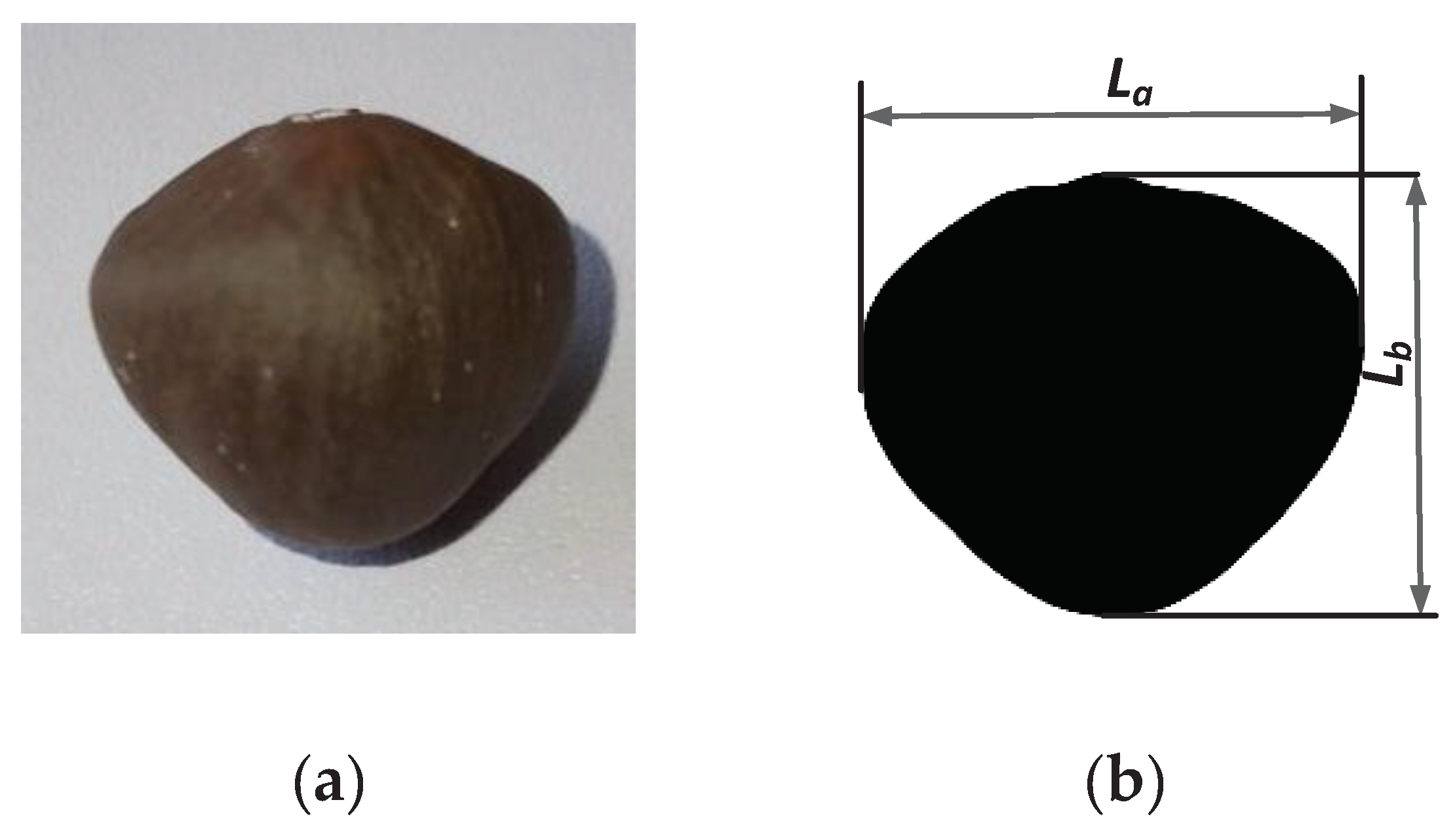
Figure 2.
Size distribution of the two tea seeds.(a) Major diameter size distribution;(b)Broad diameter size distribution.
Figure 2.
Size distribution of the two tea seeds.(a) Major diameter size distribution;(b)Broad diameter size distribution.
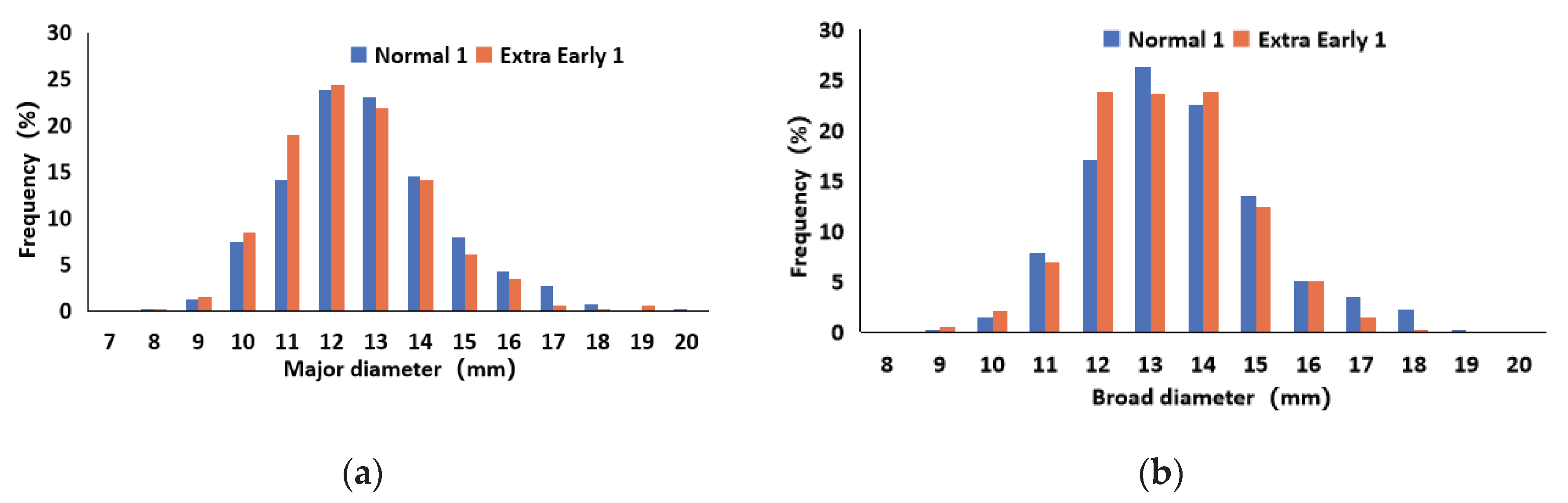
Figure 3.
Structure diagram of self-propelled electric tea seed planter.
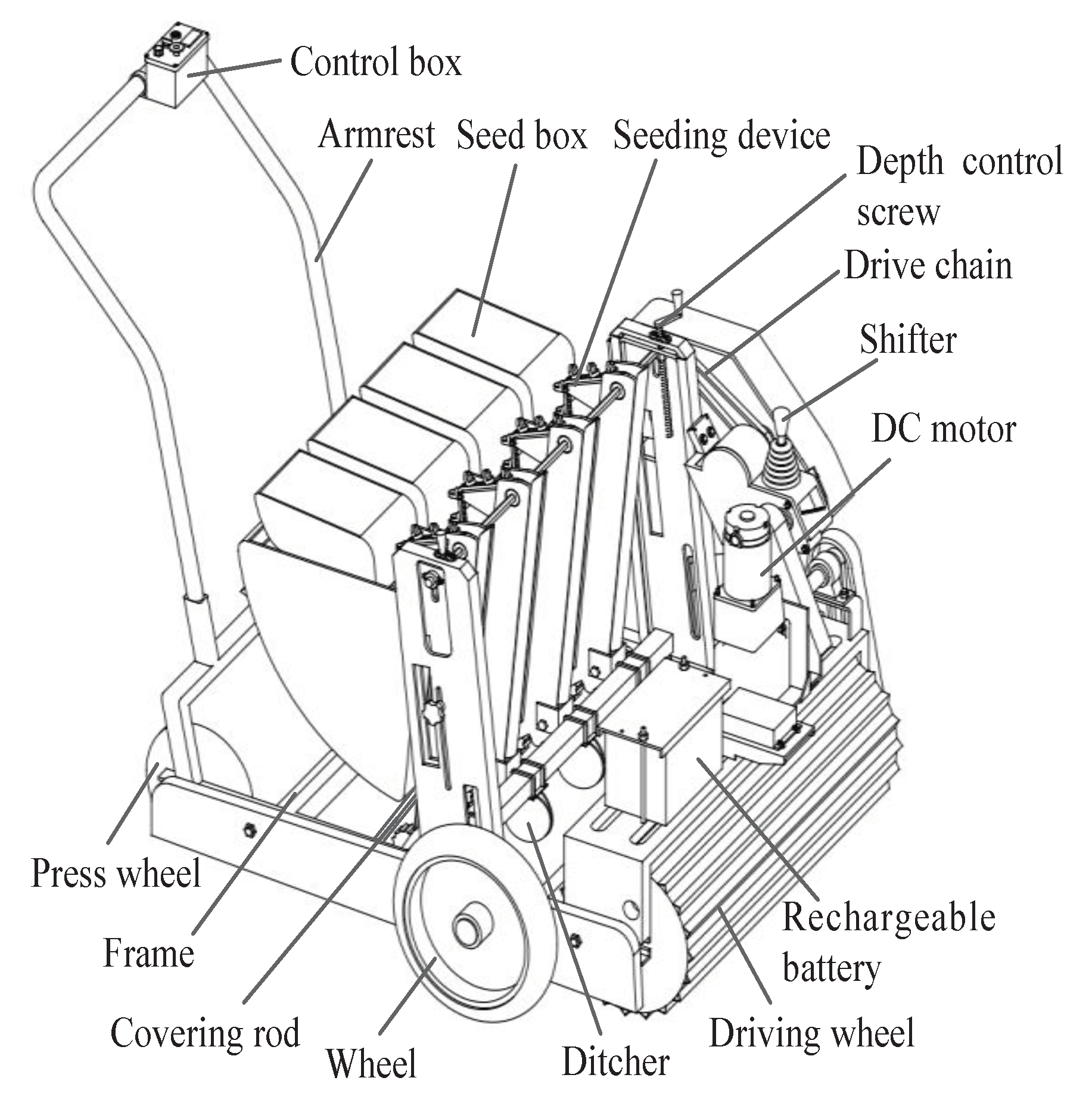
Figure 4.
Structure diagram of the seeding device.
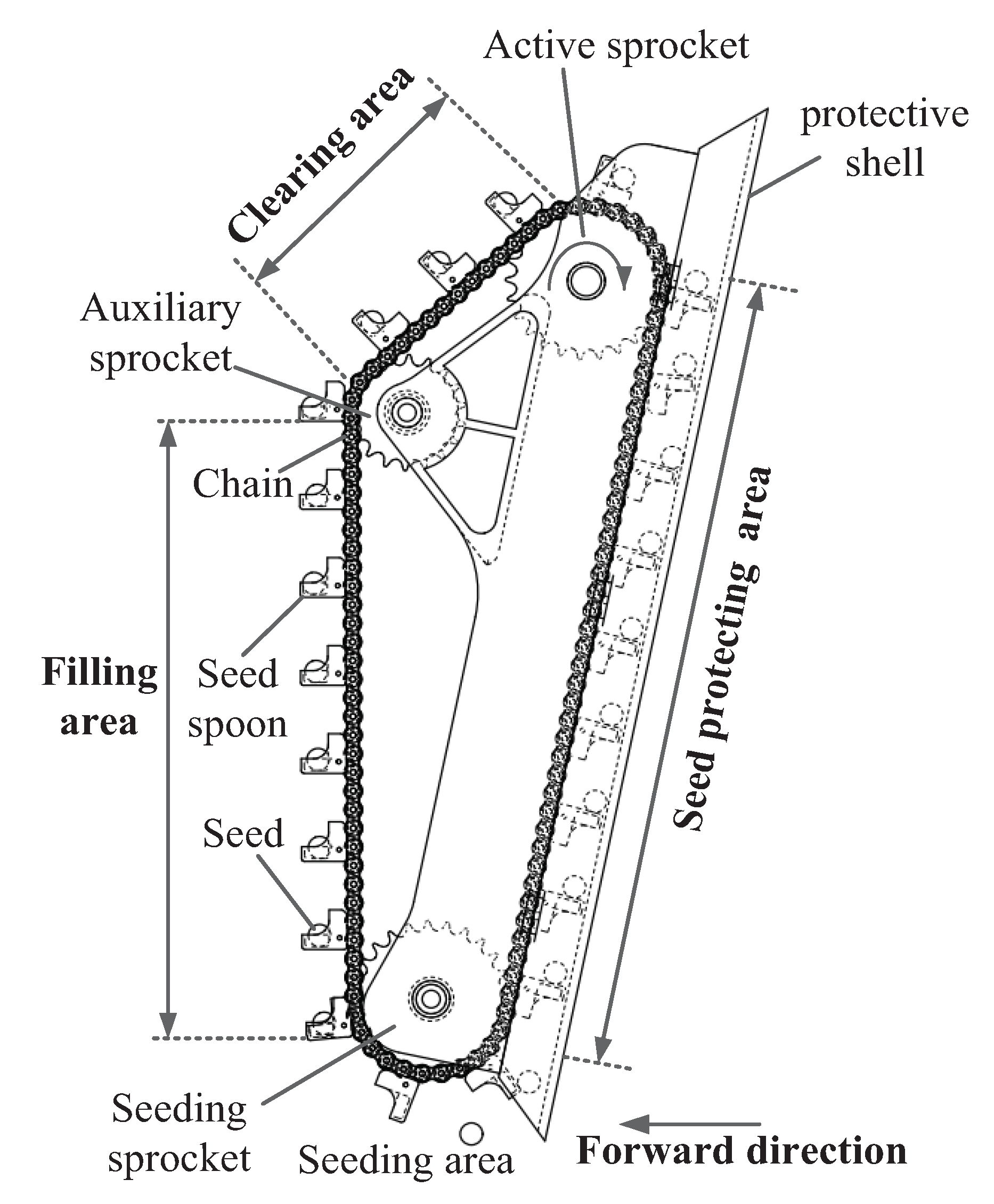
Figure 5.
Structure diagram of the double-disc ditcher.
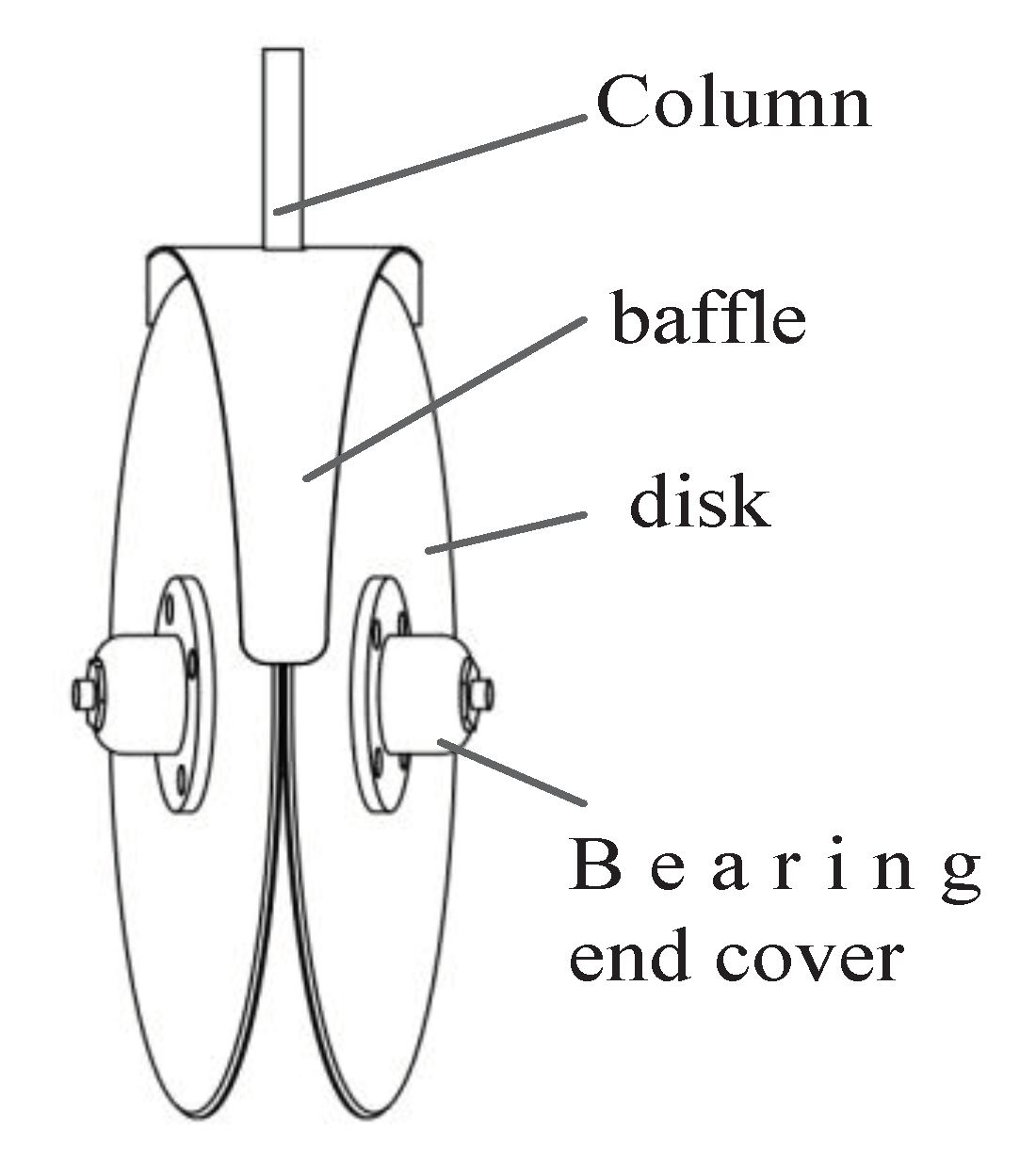
Figure 6.
Double-disc convergence point location diagram.
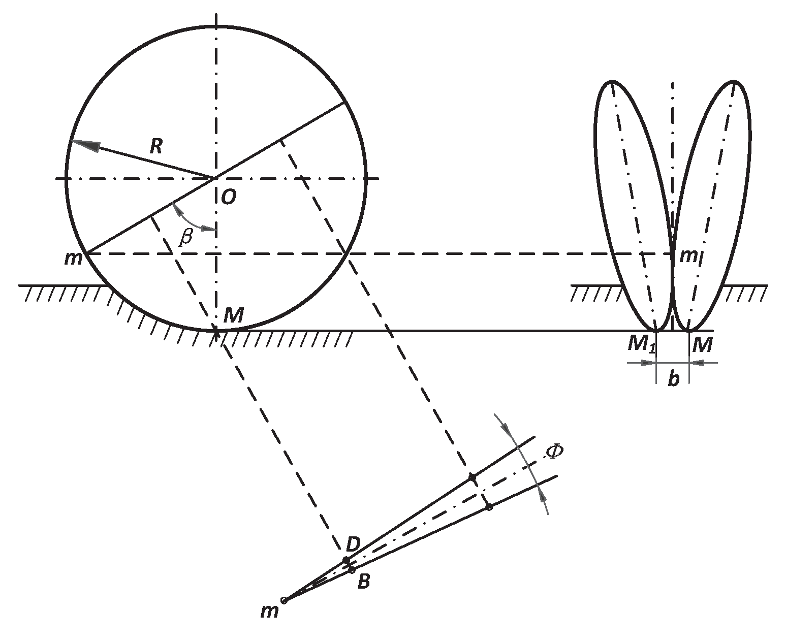
Figure 7.
Transmission system design diagram.
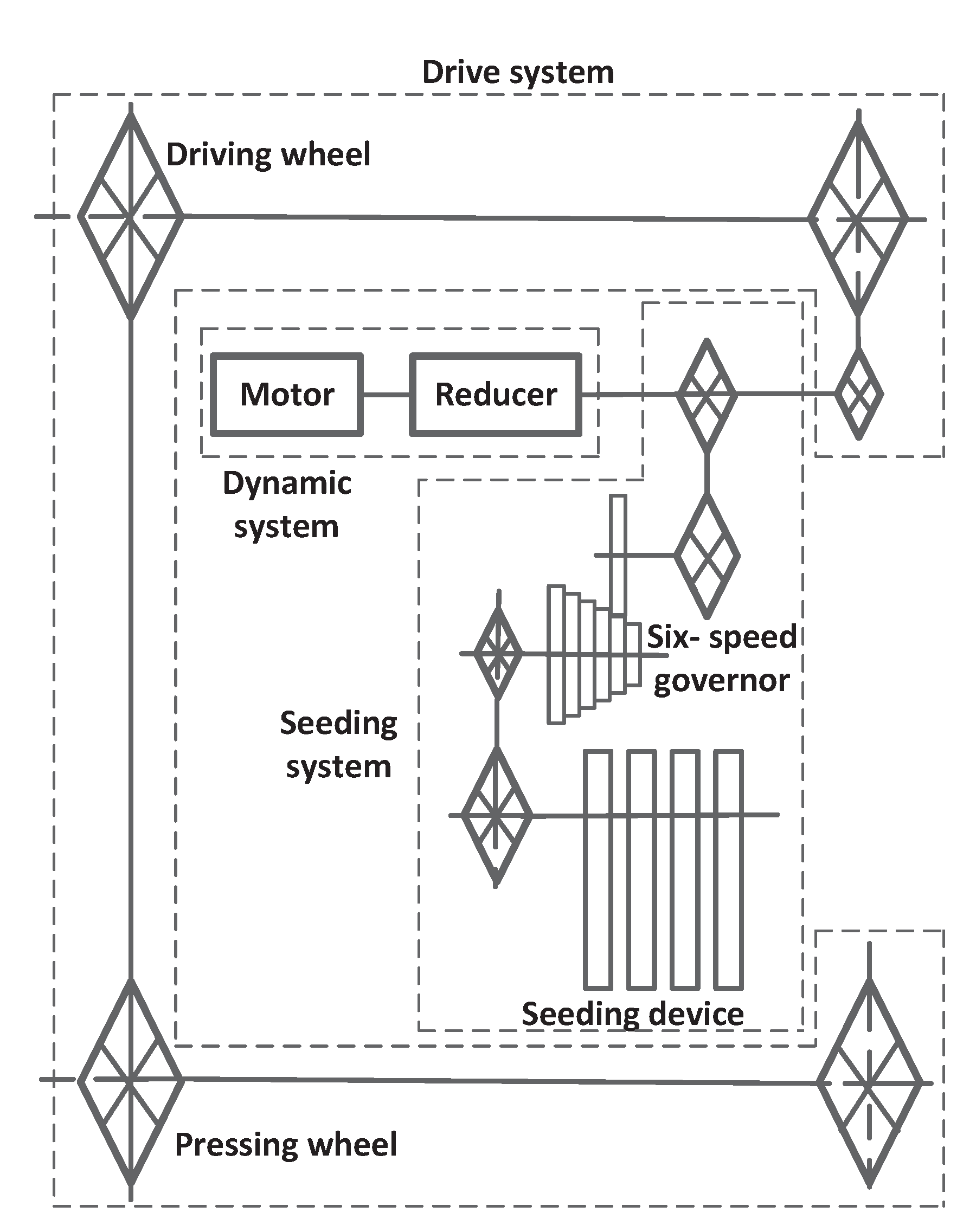

Table 1.
Structural parameters of electric tea seed seeder.
| Parameter | Value |
|---|---|
| Machine size (length × width × height)/mm | 1320 × 950 × 1140 |
| Weight / kg | 95 |
| Driving speed range / (m · s-1) | 0–1 |
| Operation width / mm | 800 |
| Number of working rows / rows | 4 |
| Line space /mm | 200 |
| Plant distance range / mm | 50–100 |
| Seeding depth range / mm | 30–50 |
Table 2.
Plant distances corresponding to different gears.
| Block | 1 | 2 | 3 | 4 | 5 | 6 |
|---|---|---|---|---|---|---|
| Theoretical plant spacing / mm | 48.3 | 58 | 67.7 | 77.3 | 87 | 96.7 |
| Designed plant spacing / mm | 50 | 60 | 70 | 80 | 90 | 100 |
Table 3.
Test factor levels.
| Factors | Levels | ||
|---|---|---|---|
| 1 | 2 | 3 | |
| Driving gear (A) | low speed | medium speed | high speed |
| Ditching depth (B, mm) | 30 | 40 | 50 |
| Planting gear position (C) | 1 | 3 | 5 |
Table 4.
Test Results.
| Order Number |
Experimental factor | Evaluating indicator /% | ||||
|---|---|---|---|---|---|---|
| A | B /(mm ) | C | AI | RI | LI | |
| 1 | low speed | 30 | 1 | 65.56 | 33.89 | 0.56 |
| 2 | low speed | 40 | 3 | 72.78 | 25.00 | 2.22 |
| 3 | low speed | 50 | 5 | 75.22 | 18.67 | 6.11 |
| 4 | medium speed | 30 | 3 | 87.22 | 8.89 | 3.89 |
| 5 | medium speed | 40 | 5 | 86.11 | 6.11 | 7.78 |
| 6 | medium speed | 50 | 1 | 77.22 | 21.11 | 1.67 |
| 7 | high speed | 30 | 5 | 82.78 | 3.89 | 13.33 |
| 8 | high speed | 40 | 1 | 76.67 | 18.89 | 4.44 |
| 9 | high speed | 50 | 3 | 85.00 | 6.11 | 8.89 |
Table 5.
Polar difference analysis.
| Evaluating indicator | Experimental factor | K1 | K2 | K3 | R | Optimal scheme |
|---|---|---|---|---|---|---|
| AI | A | 71.187 | 83.517 | 81.483 | 12.330 | A2 |
| B | 78.520 | 78.520 | 79.147 | 0.627 | B3 | |
| C | 73.150 | 81.667 | 81.370 | 8.517 | C2 | |
| Order of influence | A >C >B | |||||
| RI | A | 25.853 | 12.073 | 9.630 | 16.223 | A3 |
| B | 15.557 | 16.667 | 15.297 | 1.370 | B3 | |
| C | 24.630 | 13.333 | 9.557 | 15.073 | C3 | |
| Order of influence | A >C >B | |||||
| LI | A | 2.963 | 4.447 | 8.887 | 5.924 | A1 |
| B | 5.927 | 4.813 | 5.55 | 1.114 | B2 | |
| C | 2.223 | 5.000 | 9.073 | 6.850 | C1 | |
| Order of influence | C >A >B | |||||
Table 6.
ANOVA of the test results.[a].
| Evaluating indicator | Parameter | Sum of squares | Degrees of freedom | Mean square | F | Significance |
|---|---|---|---|---|---|---|
| AI | A | 262.185 | 2 | 131.092 | 38.585 | * |
| B | 0.785 | 2 | 0.392 | 0.116 | ||
| C | 140.190 | 2 | 10.095 | 20.631 | * | |
| Error | 6.79 | 2 | ||||
| Sum | 409.96 | 8 | ||||
| RI | A | 459.889 | 2 | 229.945 | 148.639 | ** |
| B | 3.177 | 2 | 1.589 | 1.027 | ||
| C | 369.083 | 2 | 184.542 | 119.290 | ** | |
| Error | 3.09 | 2 | 1.55 | |||
| Sum | 835.24 | 8 | ||||
| LI | A | 57.000 | 2 | 28.500 | 33.063 | * |
| B | 1.929 | 2 | 0.964 | 1.119 | ||
| C | 71.224 | 2 | 35.612 | 41.313 | * | |
| Error | 1.72 | 2 | 0.86 | |||
| Sum | 131.87 | 8 |
[a]When P<0.01, the result is extremely significant and is symbolized with “**”. When P < 0.05, the result is significant and is symbolized with “*”.
Table 7.
Verification of the test results.
| Order Number |
Experimental factor | Evaluating indicator /% | ||||
|---|---|---|---|---|---|---|
| A | B /(mm ) | C | AI | RI | LI | |
| 1 | medium speed | 30 | 3 | 87.78 | 7.89 | 4.33 |
| 2 | medium speed | 40 | 3 | 87.22 | 7.67 | 5.11 |
| 3 | medium speed | 50 | 3 | 87.56 | 7.56 | 4.89 |
Disclaimer/Publisher’s Note: The statements, opinions and data contained in all publications are solely those of the individual author(s) and contributor(s) and not of MDPI and/or the editor(s). MDPI and/or the editor(s) disclaim responsibility for any injury to people or property resulting from any ideas, methods, instructions or products referred to in the content. |
© 2024 by the authors. Licensee MDPI, Basel, Switzerland. This article is an open access article distributed under the terms and conditions of the Creative Commons Attribution (CC BY) license (http://creativecommons.org/licenses/by/4.0/).
Copyright: This open access article is published under a Creative Commons CC BY 4.0 license, which permit the free download, distribution, and reuse, provided that the author and preprint are cited in any reuse.


