Submitted:
26 February 2024
Posted:
26 February 2024
You are already at the latest version
Abstract
Automation is the key aspect of science and technology field and refers to controlling the systems for efficient output requirements. The development of robotics and similar, technologies in 21st century is a vast topic of research and significant progress has been made on this field. This research study focuses on building a ribbon-cutting robot with a Bluetooth interface for event inaugurations. The entire system hinges on constructing a prototype that is mounted on a robotic car frame with four wheels and an Arduino controller. In this case, ribbons are cut using a nickel wire, and it may be paired with an Android device via Bluetooth or an application. The robot is one of the first steps toward the development of autonomous, cognitive robots and can be used in a variety of events. Efficient temperature monitoring is done with help of LM35 sensor and Bluetooth based communication in order to monitor the conditions and effectively control the actions for which robot is designed. The robot has significantly allowed authors for desired tests on ribbon cutting and final results obtained were very exciting for its desired application target. Ribbon-cutting robots find applications in various events, including inaugurations, exhibitions, and ceremonies. Their precision and novelty add value to such occasions.
Keywords:
Arduino
; Bluetooth Interface
; Potentiometer
; Ribbon cutting robot
; Ultrasonic sensor
1. Introduction
BLE is a wireless technology that enables short-range communication and is especially energy-efficient [13]. Because of this, it can be used for a variety of purposes, particularly in the Internet of Things space. The concept of using robots to launch various events is among the most crucial elements in using automated technologies to build intelligent systems. In the past few years, significant advancements have been made in the development of robotic systems for specific tasks. The objective of this project is to combine wireless communication, robotics, and heating technologies to create a ribbon-cutting robot that can cut ribbons perfectly. Robotics integration into ceremonial events has enormous potential to produce visually stunning and unforgettable experiences. This study explores the technical details of the Ribbon Cutting Robot's development, such as its software interface, electrical control systems, and mechanical design. The goal of this research project is to design, develop, and deploy a state-of-the-art Ribbon Cutting Robot that can be operated remotely through a Bluetooth interface. In addition to improving operational flexibility, the use of Bluetooth technology and sensors is in line with the current trend of smart and connected devices. The goal of this research is to advance robotics by offering a fresh and entertaining approach to ceremonial tasks that combines modern and traditional elements. The project represents a paradigm shift in the way ceremonies are carried out in the modern era by investigating the possible applications of such robotic systems in a range of public events, from corporate functions to grand openings and inaugurations. Because of their many applications, robots with artificial intelligence are becoming more and more popular. Robust Bluetooth interfaces from earlier decades can be leveraged to create a remote-controlled system suitable for use as a robot for cutting ribbons. This strategy is crucial for creating low-cost model and applying in the occasion inaugurating application. The model we employ is completely dependent on the Bluetooth interface, a common communication interface for developing remote control systems for embedded projects. The following are the primary goals of this study project:
- To create a working prototype of a ribbon cutting robot that can be operated remotely and has a Bluetooth interface.
- To use robot to cut ribbons to officially inaugurate events.
- To increase the use of automation and robotics for various applications
Literature Review
The base, shoulder, elbow, and wrist of the robot arm are composed of movable joints, while the gripper and end of the end- effector of the arm are composed of two movable joints. The response time is recorded at the moment when the actuators are being controlled in accordance with the commands transmitted to the microcontroller via Bluetooth from the Android application. Inverse kinematics equations are used to compute the servo motors' rotating angles with accuracy. Rather than using a homogeneous transformation matrix calculation, the equations were built geometrically in order to simplify the calculation. According to the outcome, the motors' angular rotation error was less than 5%, and Bluetooth connectivity was established effectively [1]. With the use of geared motors and wheels fastened to the holder, it may also move objects from one location to another. and works it along with the cloth it gets. The automation program, in conjunction with the HC-05 Bluetooth module connected to the Arduino Uno, controls this mechanism. The code is designed to control how servomotors operate. With a few tweaks, we can transform this concept into a robotic crane, or it resembles other robotic cranes. It finds extensive application in the domains of agriculture, medicine, industrial automation, and manufacturing facilities [2]. This study suggests an inventive method of industrial equipment restraint using smart phones and android tools. This study presents an Android application that offers a user-friendly platform for communicating with robots. An intuitive graphical user interface for interacting with industrial electronics is created by the program. Bluetooth wireless technology allows robots and mobile applications to communicate with one another (IEEE.802.15.1) [3]. The design of a prototype that enables more precise control of a robotic arm during surgery through Bluetooth is covered in this study. The created prototypes have two servo motors that are powered by a motor driver to rotate the robot arm in the correct direction and to position the object after it has been picked up a set distance. The ATMEL microcontroller was programmed to control the robotic arm's movement. The robotic arm can take up and drop objects weighing up to 350 grams. Its grip extends to 6 cm and closes to 1.5 cm. The robot and smartphone application can communicate wirelessly thanks to the Bluetooth module [4]. It talks about some of the fundamental qualities that a robot needs, like intelligence, mobility, energy, and sensing. It uses software, different power supply, and control systems to accomplish a task. We created an Android software that controls the movements of an RC car via remote buttons. Therefore, the Android application on the mobile device serves as the vehicle's remote control. The USART protocol is used for communication between the Android device and the controller through Bluetooth [5]. A set of equations that transparently define the phase space of admissible motion limited by path geometry and joint torques are produced by transforming the equations of motion to this one DOF. A field of extremals bound by a maximum velocity curve, which functions as a trajectory source or sink, makes it simple to identify the time optimal solution representing the maximum mobility of the path-manipulator configuration. Due to its characteristics, an algorithm was suggested to be developed to determine the time-minimum curve given a series of accelerating and decelerating extremals. Bellman's principle is used to study additional optimizing criteria in the work s[7]. Obtaining a single, low-cost, multipurpose robot that could be utilized for outreach and education initiatives in addition to research at a cost less than ten times that of commercial platforms was the primary objective of the authors. Its control board, processing units, actuators, sensors, and body are all intricately designed. To enable the robotics community to use and improve the current version, the printed circuit board and software created for that project were made available as open source. Lastly, various ExaBot configurations are displayed, showcasing a number of applications that meet the specifications for which this robotic platform was created [8].
Several robots have been developed in recent years with versatile applications as mentioned in [1,3,4]. These robots utilize various control interfaces, including manual controllers, wireless communication protocols, and mobile applications. Traditional ribbon-cutting robots often rely on manual controllers with physical buttons or joysticks for operation. These controllers offer precise control but may lack the convenience and flexibility of wireless interfaces. A notable advancement in ribbon-cutting robots is the integration of wireless communication protocols and sensors for remote controlling action and monitoring. This enables remote operation and eliminates the need for physical tethering. Examples include Bluetooth, Wi-Fi, and RF communication. Some ribbon-cutting robots have successfully integrated with Android applications, allowing users to control the robot via a mobile device. This enhances accessibility and user-friendliness. The development of autonomous, cognitive robots represents a significant advancement in robotics technology. These robots possess the ability to make decisions based on sensory input and adapt to changing environments. Ribbon-cutting robots find applications in various events, including inaugurations, exhibitions, and ceremonies. Their precision and novelty add value to such occasions. Based on our comparative analysis, we believe that the proposed ribbon-cutting robot with a Bluetooth interface represents a noteworthy contribution to the field. It combines the convenience of wireless control with the potential for further autonomous and cognitive advancements, making it a promising step forward in robotic event technology.
2. Material and Methods
An important development in the subject is the Bluetooth interface. It is a promising improvement in robotic event technology because it combines the ease of wireless control with the possibility of additional autonomous and cognitive advancements. Our method involves heating and adding nichrome wire to a ribbon for the purpose of cutting ribbons and launching ceremonies. It is based on earlier ideas of robotic cars that are operated by Bluetooth and interface with Android phones. The primary system used in this work is a remote-controlled robot that can be used for inauguration of an event. Different sensors have been utilized for the purpose of automating the robotic actions and movement along with Bluetooth communication has been used for the remote controlling and monitoring of the conditions utilized for desired target.
Figure 1.
A ribbon employed for inauguration of an event.

The core brain of the system, an Arduino microcontroller, controls the assembly of a Bluetooth-controlled interface using motors and a robotic car frame that are readily accessible in the market. Since cutting the ribbon and starting the ceremony are crucial and essential components of an event, robotic systems can be used to do these tasks.
2.1. System Architecture
Figure 3.
System architecture.
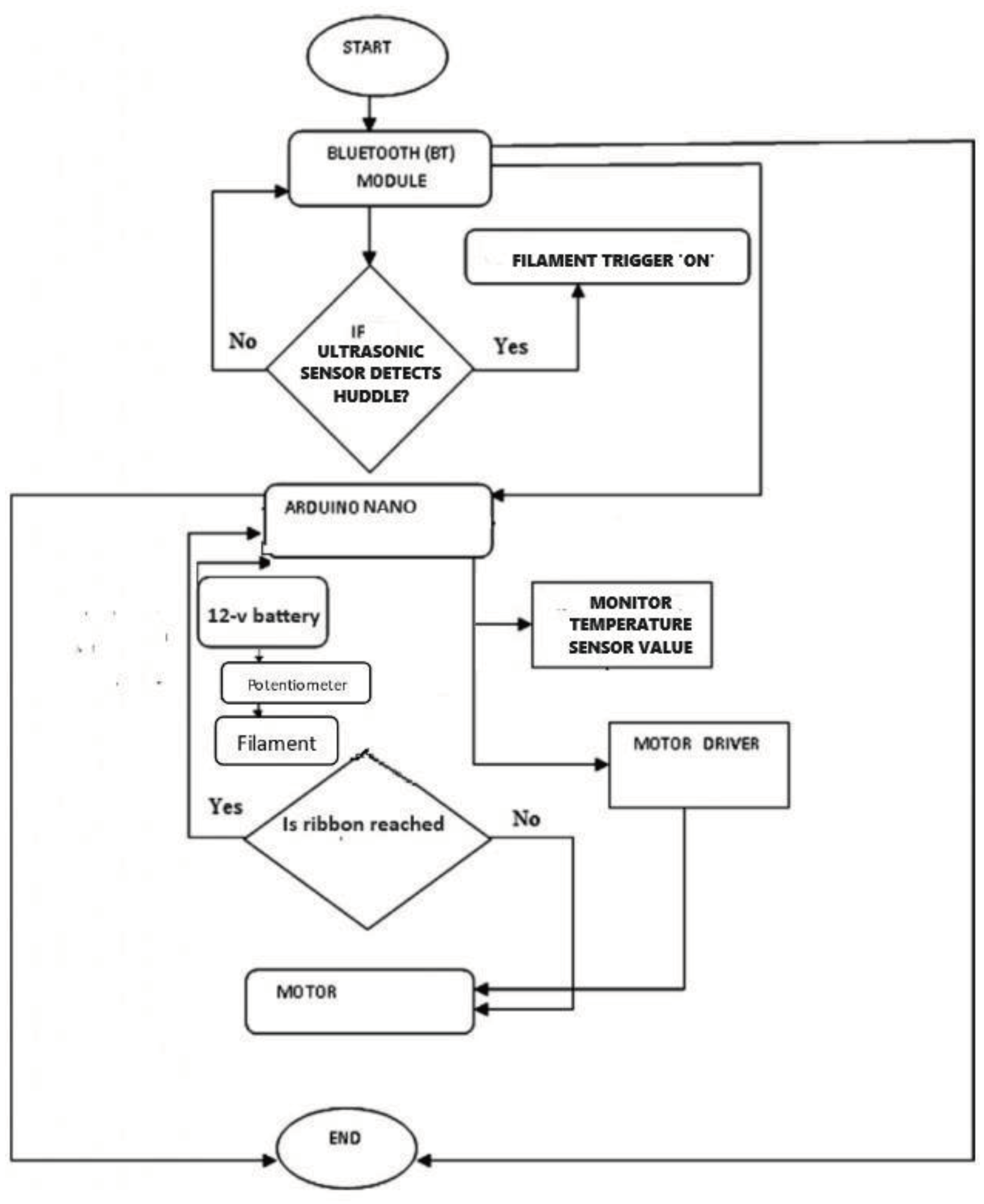
The four-wheeled robotic body, which is the key component of our ribbon-cutting robot, is driven by an Arduino microcontroller- powered motor driver. Bluetooth interface allows for remote control of the device. Here, the robot's body wheels are powered by the motors. The temperature sensor LM35 effectively helps monitor the temperature and ultrasonic sensor allows distance calculation and also detects the huddle and activate the ribbon cutting system. The ultrasonic sensor has been activated for a desired range of upto 10m to which it can support the HC-05 based remote controlling on the robotic body. This effectively helps to monitor the system conditions and also allows users to perform desired action remotely.
When a ribbon acting as a huddle within range of ultrasonic senor acts as a huddle detected then, it effectively triggers the system and heating element which has been set up to desired temperature by the potentiometer is activated and user can remotely move the robot body towards the ribbon to be cut and effectively this allows successful event inauguration.
System block diagram
Figure 4.
System block diagram.
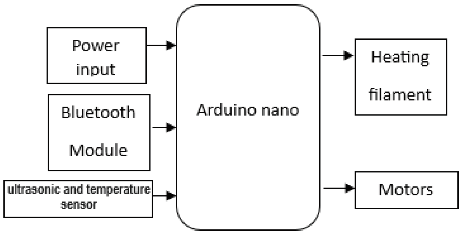
Our system comprises up of different sensors and modules integrated for desired application and motors are sed for controlling robotic body movement. The sensors are interfaced with Bluetooth HC-05 interfaced communication protocol which allows remote monitoring of temperature on android devices.
Hardware assembly
The project makes use of an Arduino microcontroller integrated into a 4-wheel robotic car frame. The Arduino is in charge of the motor drivers, which are connected to the motors. If there are any sensors, they are linked to the proper pins on the Arduino board.
Bluetooth module Integration
To enable remote control, the system has a Bluetooth module (HC-05). The module creates a wireless communication link with a mobile device by connecting to the Arduino and powering it.
Controller Interface
The setup includes a potentiometer to control the nichrome wire's temperature. This makes it possible to precisely control ribbon cutting, guaranteeing precise and clean cuts.
Filament
Nichrome wire is a key component used in the ribbon cutting robot project to achieve accurate and controlled cutting. Because of its exceptional heat-generating capabilities and strong electrical resistance, nickel-chromium wire, or nichrome wire, is a popular option for applications needing regulated heating.
Motor Configuration
Two motors are fitted to the four-wheeled vehicle, one for each set of wheels on either side. When these motors work together, the robot's movement may be precisely controlled.
Motor Driver Integration
Motor drivers have been used to enable smooth communication between the Arduino and the motors. By converting the digital signals from the Arduino into the appropriate power and voltage levels needed to control the motors, these electrical components act as intermediate interfaces.
PWM signal modulation
PWM, or pulse width modulation, allows the Arduino to precisely control each motor's speed and direction. The PWM signal's duty cycle can be dynamically adjusted to allow the motors to operate in both forward and backward directions, giving them a broad range of speeds.
Ultrasonic sensor
The circuit in our project that links the nichrome wire to the power supply incorporates the use of ultrasonic sensor to calculate the distance and trigger the filament. We can successfully regulate the quantity of electrical current passing through the wire by adjusting the potentiometer. The temperature at which the nichrome wire functions is thus determined by this.
Potentiometer
The potentiometer used allows the nichrome wire element to adapt required temperature as the main user can set a desired range of temperature by the use of potentiometer.
Temperature sensor
A LM35 sensor attached to the frame at the top allows the temperature recording of the filament adjusted nearer to it. This is useful in order to monitor the filament temperature value and allows the efficient control on system remotely, as for any situation the fault analysis can be made on the filament and it is also efficient to prevent overheating.
Furthermore, a wooden frame has been utilized in between the potentiometer and voltage source connections, where the nichrome wire is positioned. The nichrome wire can be activated by detecting the ribbon by use of sensor and also desired temperature range can be setup before deploying the robot in the action by use of a potentiometer.
Circuit breakdown for robot
Figure 5.
Circuit diagram for robot body.
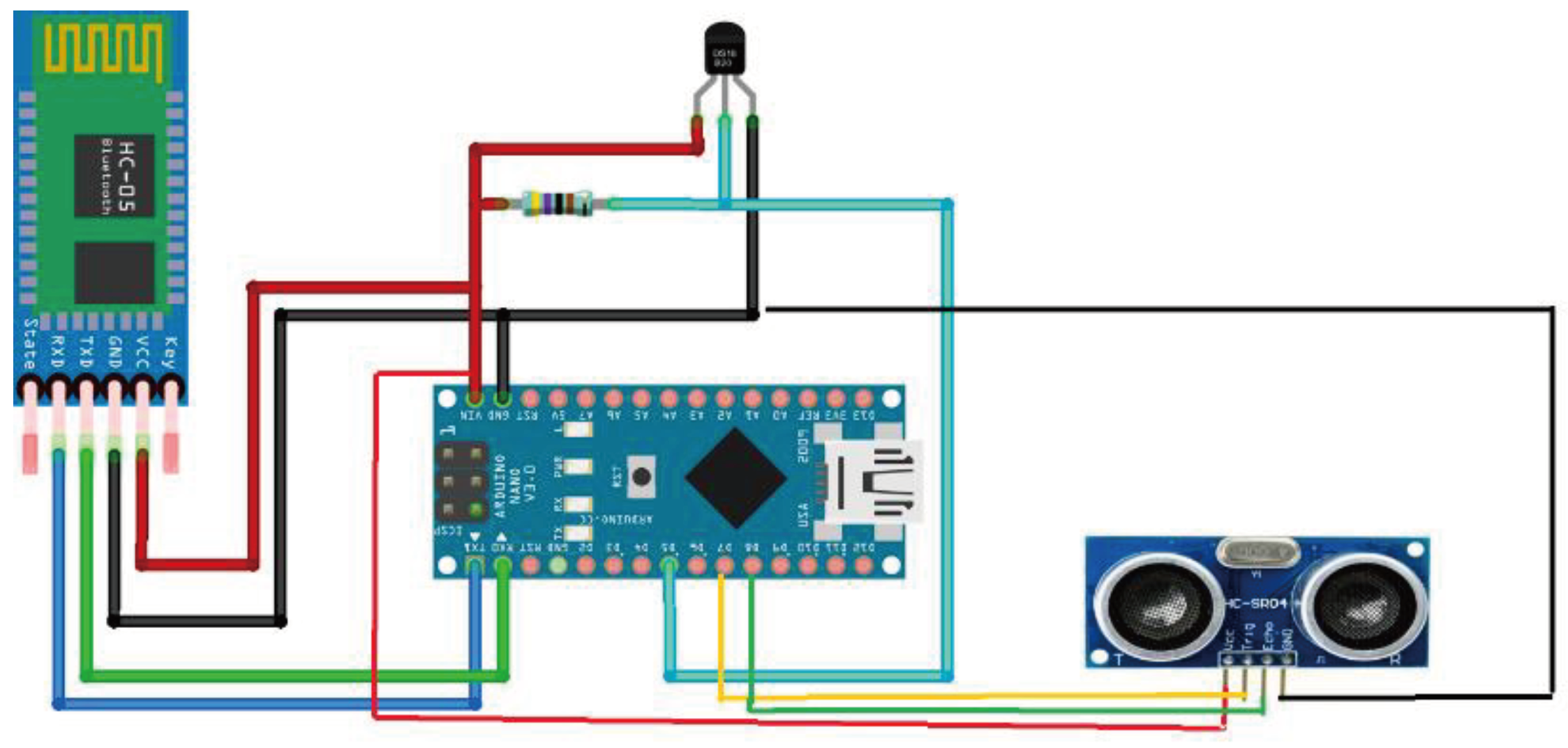
The robot system is composed of a Bluetooth module interfaced to operate the robot movement process, an ultrasonic sensor to calculate distance and process filament heating by triggering it. A motor driver, and motors are utilized to control the movement of robot and similarly, the heating filament can be set up to desired range by the use of a potentiometer. The temperature sensor LM35 module attached to the top of the wooden frame allows to monitor the temperature at the filament remotely and allows effective control on the required temperature for ribobon cutting system development. For the range of ultrasonic sensor we have,
Where:
Speed of Sound (in air) is approximately
343m/s at room temperature.
Through their communication, a mobile application interfaced to a Bluetooth module controls the motors precisely and their direction. Nichrome filaments are interfaced with potentiometers to regulate voltage levels and, when necessary, cut ribbons by heating the filament.
Fritts equation
The range of a Bluetooth connection can be calculated using the Friis transmission given in equation.1.
- Pr is the power received at the receiving antenna in watts
- Pt is the power transmitted from the transmitting antenna in watts
- Gt is the gain of the transmitting antenna
- Gr is the gain of the receiving antenna
- lambda is the wavelength of the signal in meters
- d is the distance between the transmitting and receiving antennas in meters
- pi is the mathematical constant pi
This study examines the use of the Friis transmission equation to evaluate received power in the wireless communication component of our robot project that cuts ribbons. Although the main goal of our research is to create an autonomous robot that cuts ribbons, smooth operation and control depend on effective wireless connection. The efficacy of our Bluetooth interface is directly impacted by the relationship between transmitted power, antenna gains, wavelength, and distance, which may be better understood with the help of the Friis equation.
Figure 6.
Wireless communication system.
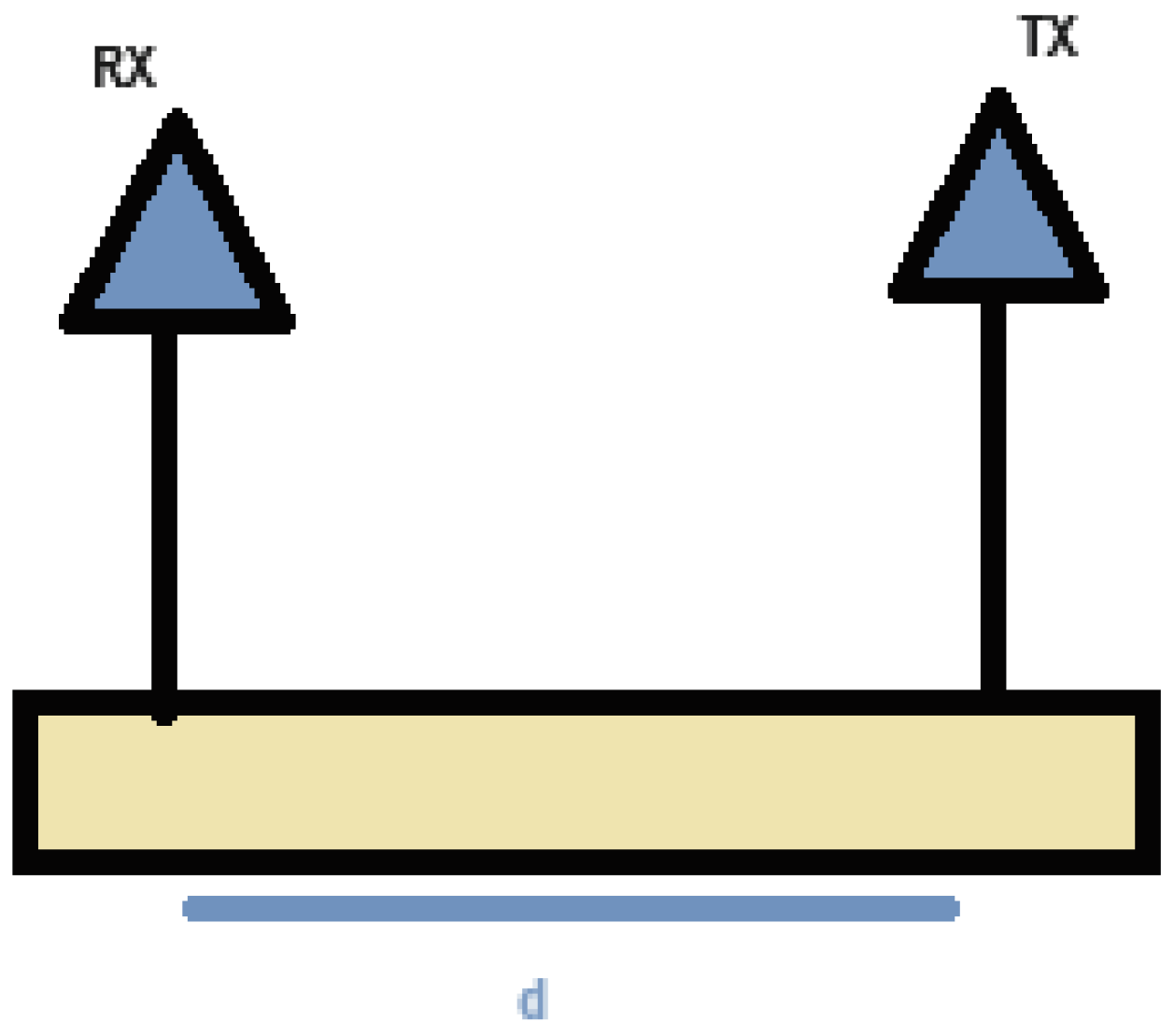
We seek to maximize the Bluetooth communication range between the Android device and the ribbon-cutting robot by integrating the Friis equation, guaranteeing dependable and sturdy control during event inaugurations.
2.4. Filament Setup
Figure 7.
Nichrome V-I characteristics.
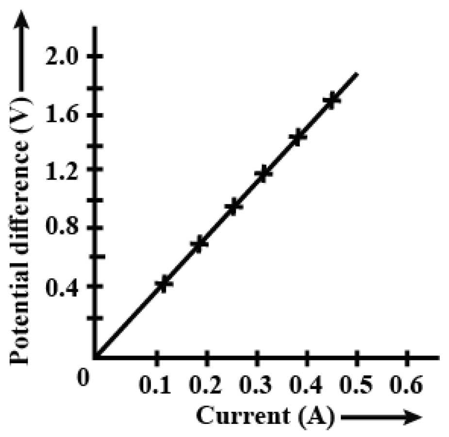
The nichrome wire's V-I graph displays a straight line. It indicates that when the current supply is altered, the wire's resistance does not change. It is regarded as an ohmic conductor since it follows the ohm's low.
It adheres to Ohm's law. →
𝑉 = 𝐼𝑅........................................................................Equation.2.
3. Results and Discussions
The Ribbon Cutting Robot is designed to be a flexible and easy-to-use tool that dignitaries or event planners can operate with ease using a tablet or smartphone. The robot was able to successfully communicate with a wireless interface by integrating Bluetooth connectivity, which removed the requirement for direct physical contact. The sensors that were used were very helpful in providing the desired values for robotic action control and remote temperature monitoring. This guarantees a safe and dependable performance of the ribbon-cutting ceremony in addition to improving the ceremonial experience.
A key component of the robot's accuracy is its careful manipulation of the nichrome wire, which is an essential component of the ribbon-cutting mechanism. The system's integration of a potentiometer enables accurate temperature control over the wire. This degree of control is crucial because it guarantees a precise and elegant ribbon-cutting, producing an aesthetically pleasing and ceremonially meaningful moment.
We tested the filament extensively to confirm the stability and functionality of the system. The goal of this extensive testing phase was to find and fix any possible problems with the robot's functionality so that it would function perfectly during the ceremonies. The system was adjusted based on the test results, which made it stable and resilient enough to endure the changing nature of live events. By successfully demonstrating precise control over the procedure, this robot gave users a flawless experience via the well-thought-out mobile application interface. A crucial part of the setup, the Bluetooth module kept a steady and dependable wireless connection open, enabling the user's mobile device to send commands to the Ribbon Cutting Robot in real time. This wireless capability adds to the overall flexibility and safety of the ceremonial process in addition to improving user convenience.
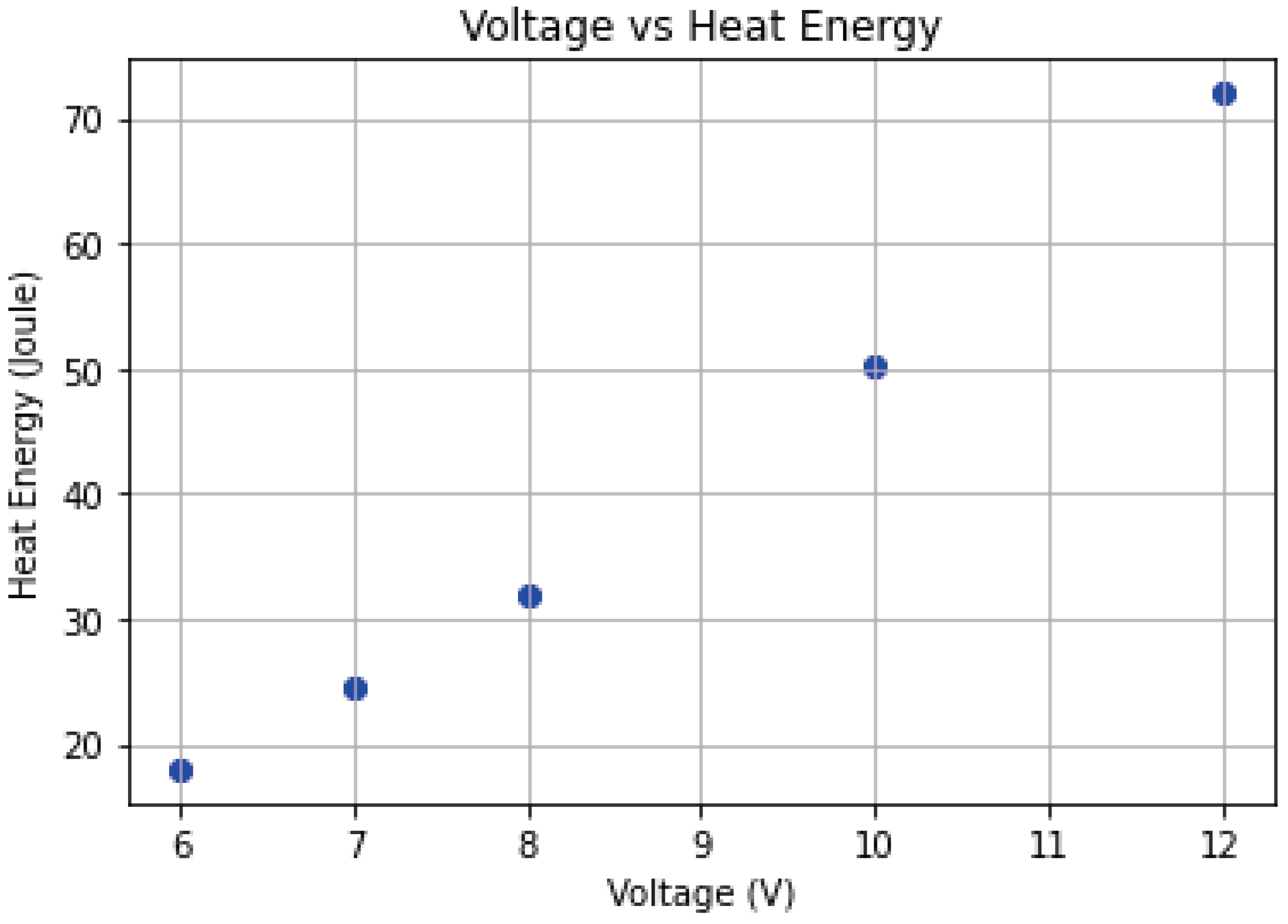
Figure 8.
a) Voltage vs heat energy plot. b). Heat Energy vs time plot.
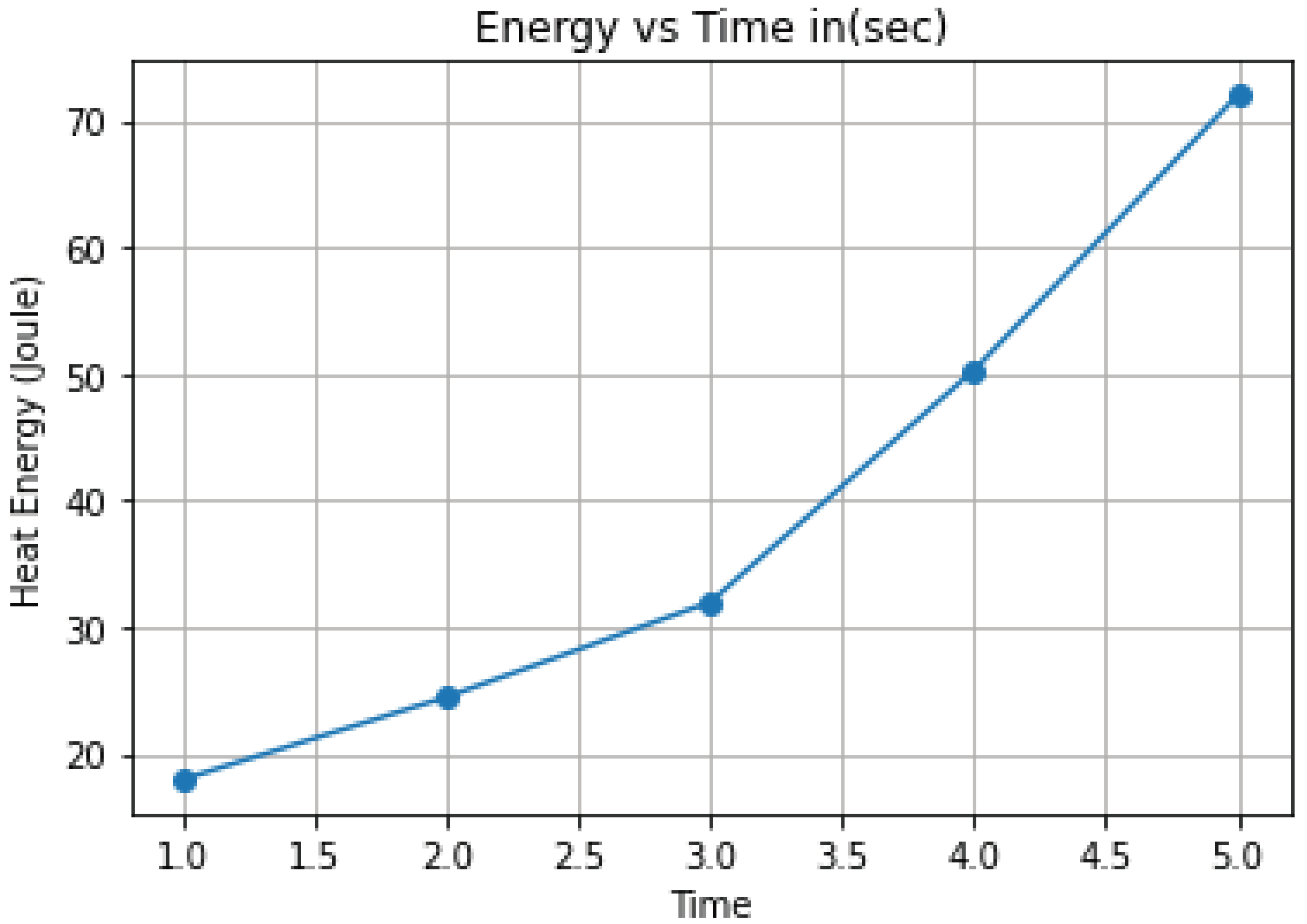
As shown in Figure 5, the graph "Energy vs Time in (sec)" depicts the relationship between time in seconds and heat energy in joules. The x-axis, labeled "Time," ranges from 1.5 to 5.0 seconds, representing the period of the measurements. The y-axis, labeled "Heat Energy (Joule)," runs from 10 to 70 joules, demonstrating the fluctuation in energy levels measured during the experiment.
The line graph demonstrates a constant rise in heat energy over time. Beginning at about 1.5 seconds, the energy level is roughly 10 joules and progressively climbs with time, reaching around 70 joules at the conclusion of the 5 second interval. This rising trend in energy implies that the system under observation accumulates heat over time, implying a positive relationship between the two variables.

Table 1.
Heat energy generation test results.
| Iteration no. |
Voltage in (v) | Time in sec | Heat energy (Joule) |
|---|---|---|---|
| 1. | 6v | 5sec | 18 |
| 2. | 7v | 5sec | 24.5 |
|
3. |
8V |
5sec |
32 |
| 4. | 10v | 5sec | 50.3 |
| 5. | 12v |
5sec | 72 |
2.4. Simulation results
Figure 9.
Proteus simulation.
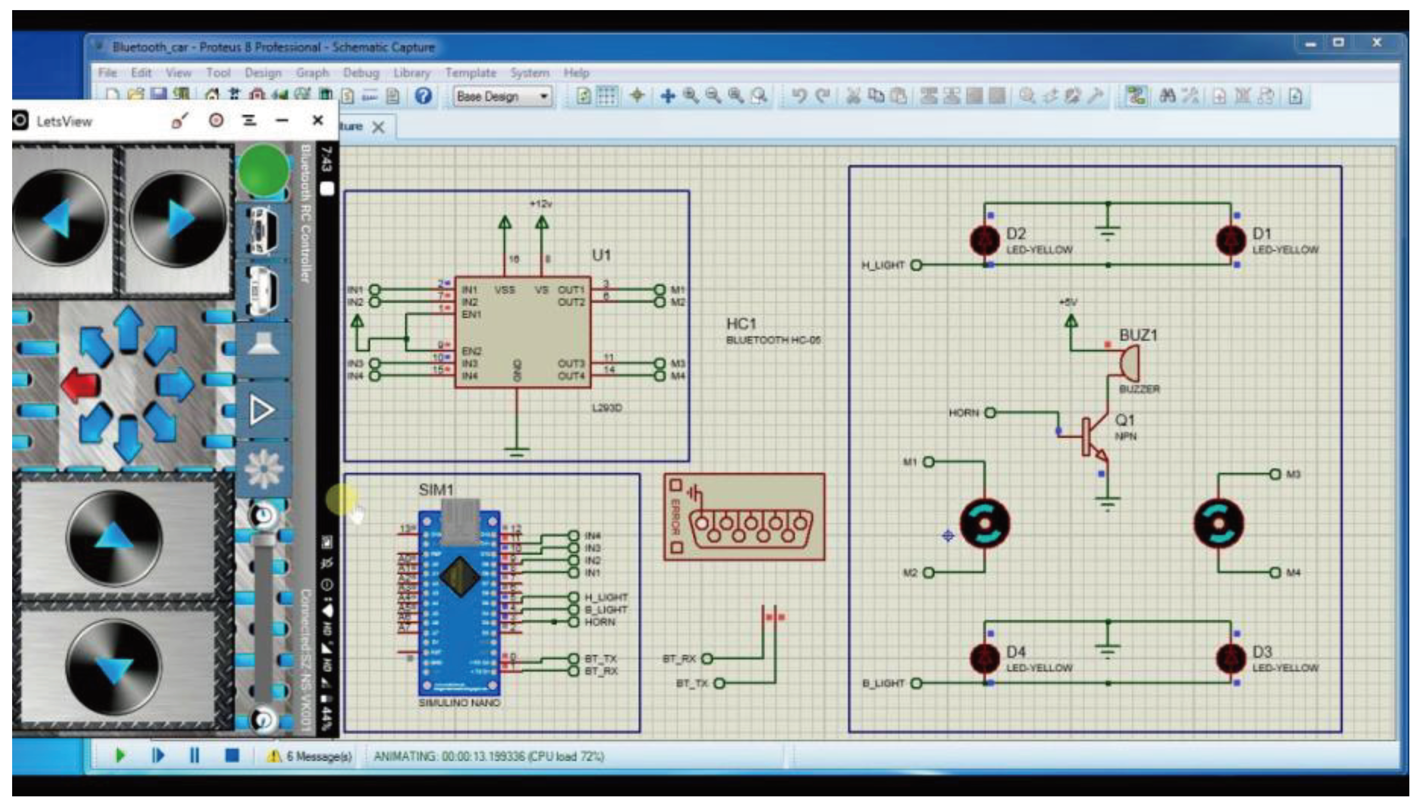
An Android application emulator has been utilized to interface a Bluetooth controller application with our suggested system, and a simulation is run to test the functionality of the proposed robotic system As, per the simulation, motors are interfaced with the system as per our suggested circuit schematic, and the motor driver is controlled by an Arduino Nano. Figure 9. illustrates how well our system functioned throughout the simulation process and produced results that were appropriate for hardware development. Later, we created a complete hardware system to test the robot.
Figure 10.
Arduino nano, LM35 and HC-05 connection.
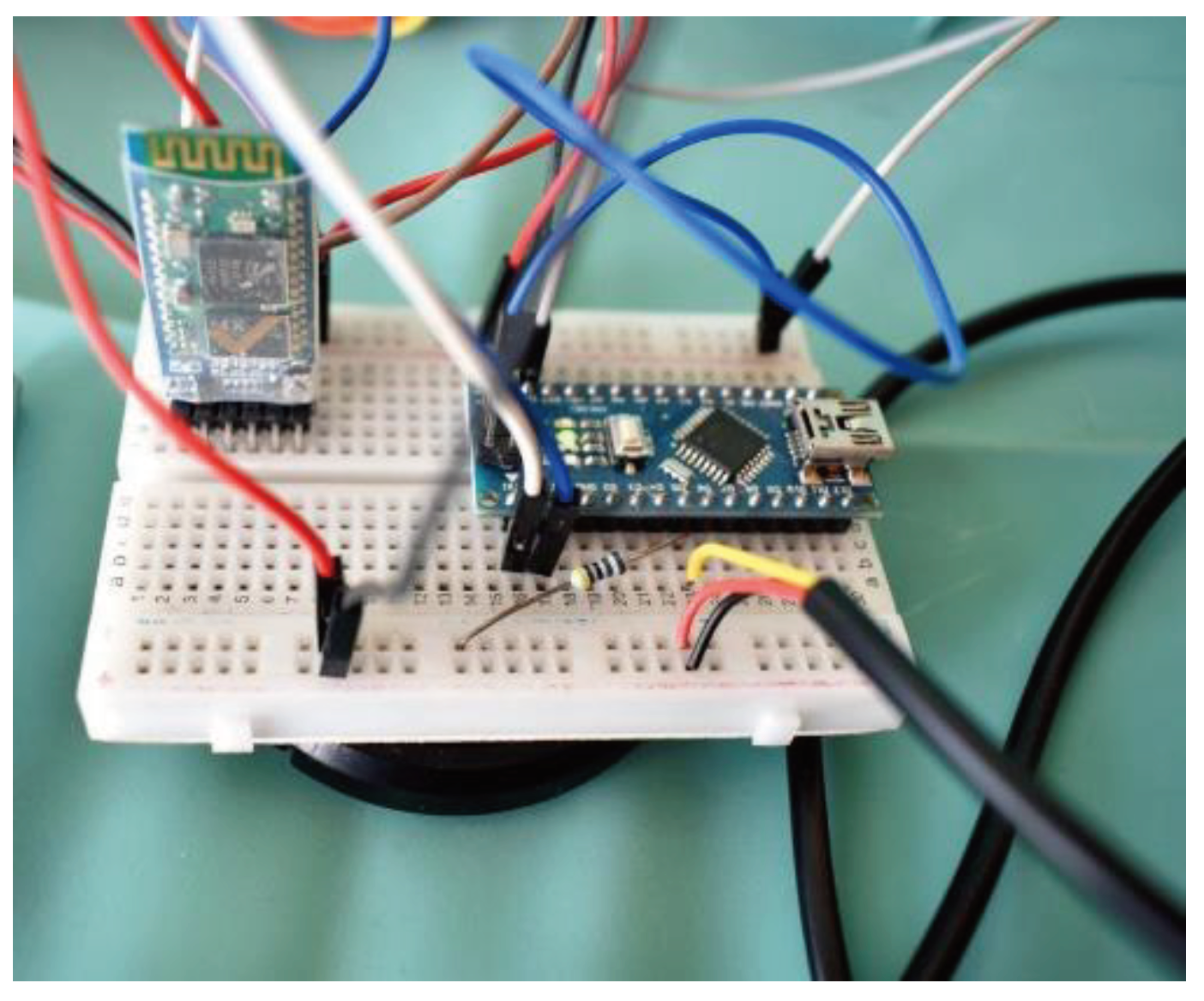
The system circuit is interfaced with an Arduino nano and other components. The Bluetooth module used can be setup to obtain desired range and also helps in effective controlling the system conditions, robotic body movement and remote monitoring of temperature sensor LM35 values. The system comprised up of LM35 sensor for temperature monitoring and this is very vital to monitor the temperature at which the filament or heating coil is working on. The potentiometer is useful for the purpose of pre-adjustment of heating filament temperature level setup.
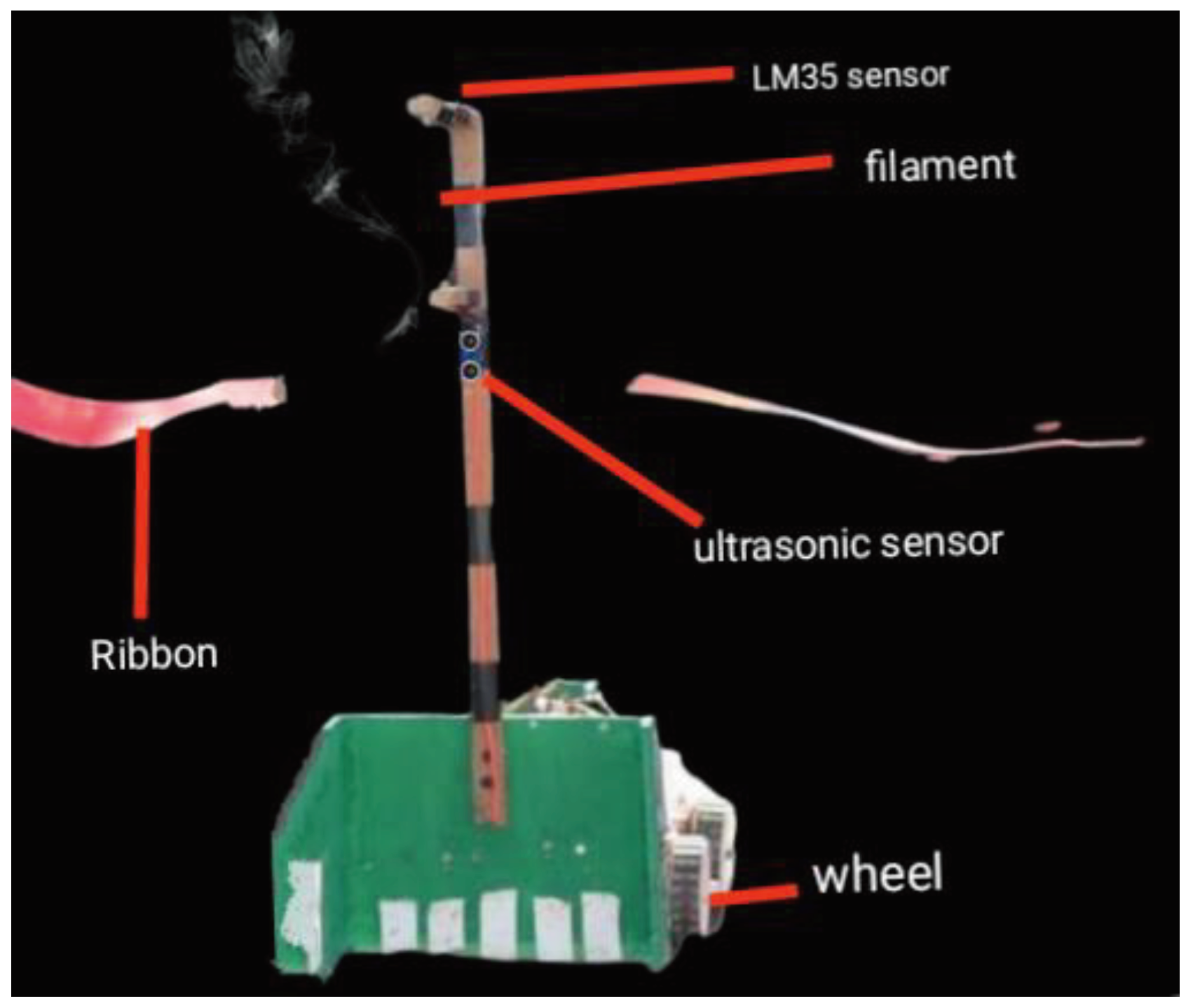
2.5. Ribbon cutting system
Figure 11.
Robot lower body developed.
The robot was able to properly cut the ribbon and start the ribbon- cutting ceremony at our event, as seen in Figure 8. Using four-wheel robot body controlled with the Bluetooth interface, the ribbon could be effectively controlled, and ribbon cutting worked flawlessly through every test iteration. The frame is integrated with a wooden body in order to accurately add all the key components for robot body development like sensors, filament and battery etc. As, shown in Figure 10 the lower body of robot was developed and tested successfully and later the ultrasonic wire reachability was expanded to reach tip of the holding part of frame for nichrome wire.
Figure 11.
Temperature monitored via Bluetooth.
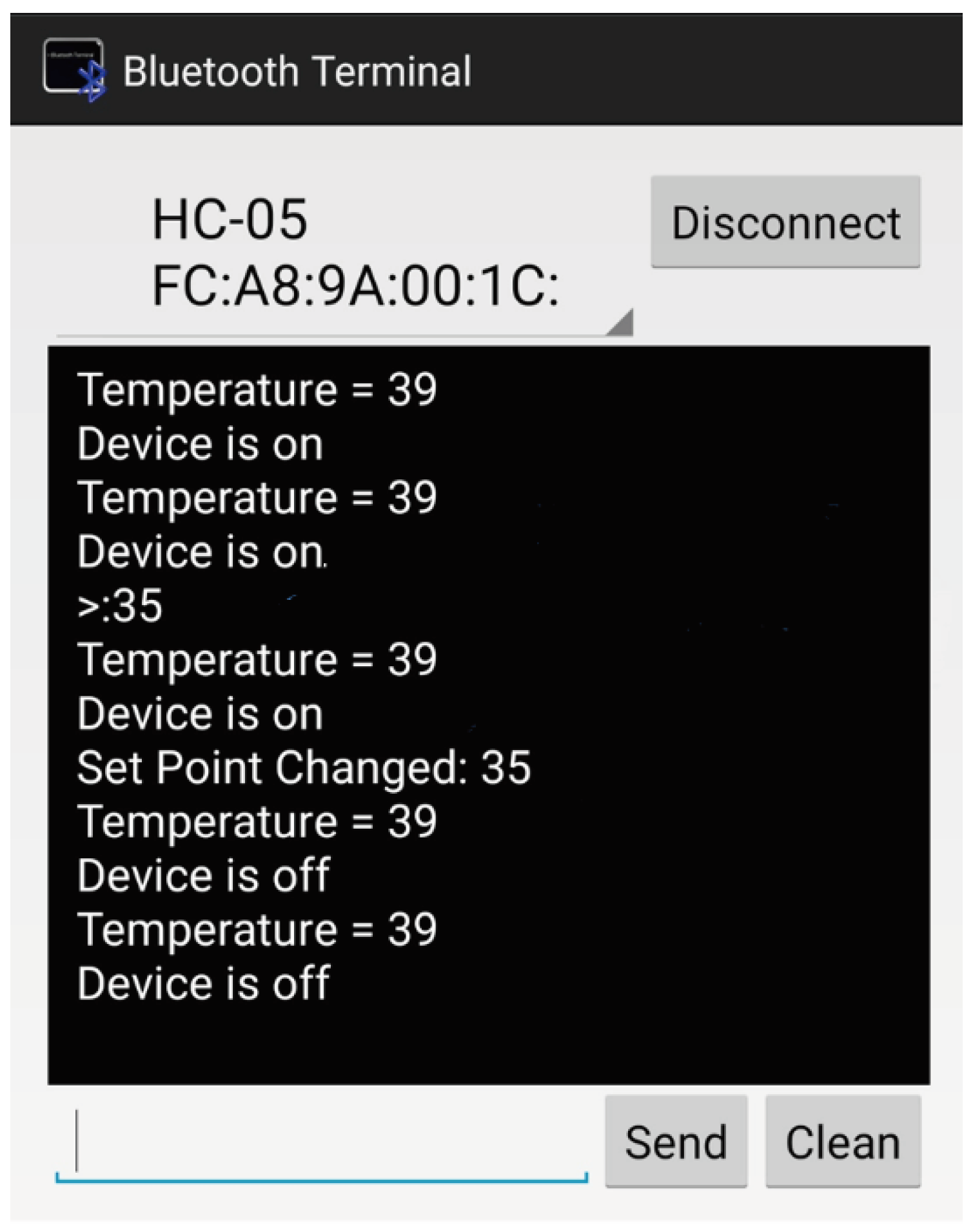
Through the use of a Bluetooth application, it was possible to successfully monitor the temperature and establish communication with the robotic body and movement at a desired range of 10 meters. In addition, the LM35 sensor could later detect the temperature at which the filament is adjusted with a higher temperature at which it cuts the ribbon, allowing users to analyze faults and take precautions against heating-related damages and accidents that could have been caused by the high temperature range. This temperature at normal conditions allowed users to evaluate the desired temperature for ribbon cutting. Similarly, the necessary setup could be made by using a potentiometer.
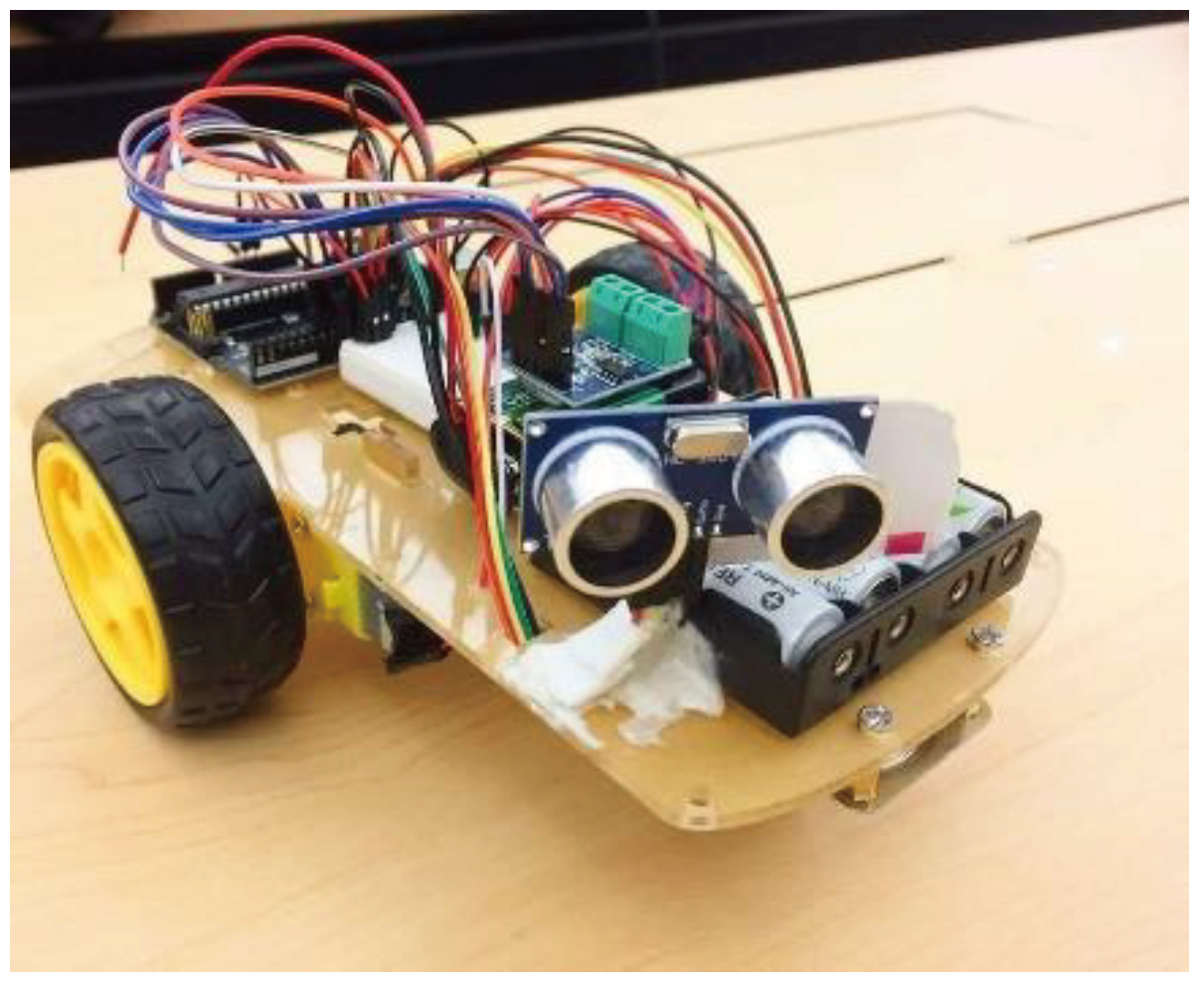
Figure 12.
Robot body.
The robot's Bluetooth interface allowed for excellent control, and an Android application allowed the robot to move to the specified location. The application for Arduino-based Bluetooth control is used for the purpose of controlling robot movement. Successful, ribbon cutting has been carried out by the utilization of the robot as shown in Figure 9. the ribbon has been cut using the robot that have been remotely controlled by the authors.
In order to determine the energy in joules required to cut a ribbon with 12-volt nichrome wire, we conducted a test in which we heated a nichrome wire for five seconds, which was suggested as a standard time. According to the table, about 72 Joules of heat energy were generated in 5 seconds. The voltage level may be adjusted with a potentiometer to control the 72 Joules of heat energy or approximate range to this. The Bluetooth module HC-05 has a 10meter range so, it was essential to test the ribbon cutting with the range variation over different iteration of tests. We carried out range test for Bluetooth module for ribbon cutting.
According to the findings of several tests, Bluetooth conferencing with a range of up to 10 meters operated really well for remote robot control. A true implies that the Bluetooth interface confronts disconnection at that displacement, however a false denote that the range is supportive of the communication between the two systems, indicating that the ribbon cutting is successful. The ultrasonic sensor allows triggering of the filament when the system detects any object nearby it and also allows the monitoring of distance. The ultrasonic sensor calculated distance can be given by equation .4.
To evaluate the robot's performance at a greater distance from the controller, this test is essential. With the Bluetooth module's real range being 10 meters, we were able to successfully cut the ribbon and establish a Bluetooth connection at the various ranges listed in the Table 2. This was a useful method for determining the system's ability to work at different distances and for creating a fully functional remotely operated robotic system.
Table 2.
Range test results for HC-05 module.
| Iteration no. |
Ultrasonic sensor range | Temperature monitored using LM35 sensor | Filament Triggering |
|---|---|---|---|
| 1. | 5m | 40°c | True |
| 2. | 8m | 48°c | True |
| 3. | 11m | 54°c | True |
| 4. | 7m | 55°c | True |
| 5. | 3m | 43°c | False |
| 6. | 10m | 58°c | True |
| 7. | 12m | 48°c | False |
Figure 13.
Application screen interface.
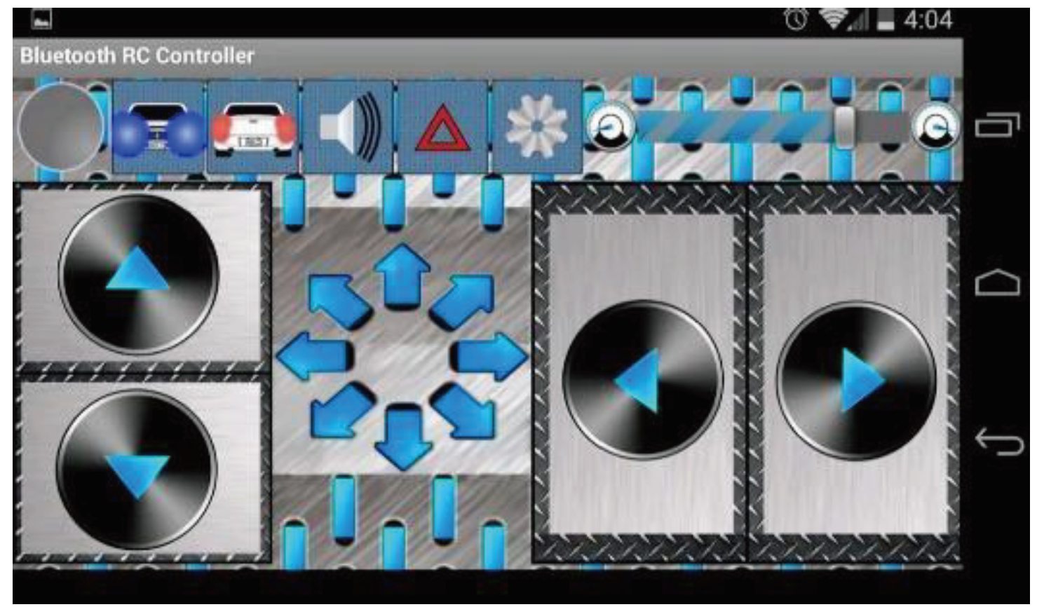
The robotic body movement is controlled by an application interface, as seen in Figure.10. This can be used to move the robot in the direction of the ribbon, cut it, and inaugurate the event, as seen in Figure 9. This enables the user's smartphone to effectively control the robot via Bluetooth interfacing with the robotic circuit attached HC-05 Bluetooth module.
Using this robot, we were able to cut the ribbon with success. Iteration tests were also conducted for the filament heating test, which proved to be highly effective in helping to finalize the prototype. The model was also used for the opening of an event.
In the future, we hope to create an autonomous ribbon cutting and path tracking system driven by computer vision that can also be used for other kinds of tasks and alter the amount of heat energy needed for autonomous ribbon cutting. In order to produce an intelligent robot in the future, the remote-controlled system may be replaced by an OpenCV based ribbon detection and path detection system. The robot can be advanced with a color detection-based computer vision system or IoT implemented system with a higher range that could support multiple features and similarly, can operate in diverse conditions can be designed and implemented. This work can have advancement and wider applications on various other kind of works which would be fruitful for diverse monitoring situations and then, accurate action can be done using such system.
Future work may involve a variety of feature additions and integrations. The robot has a range of features that can be adjusted to calculate distance. In a similar vein, features can be modified by applying methods with a more precise, goal-oriented heating element. The next era will undoubtedly be dominated by robotic systems that incorporate artificial intelligence technology. As such systems are developed and modified, a larger portion of research can be dedicated to their development.
4. Conclusions
Thus, With the assistance of this ribbon-cutting robot, we were able to effectively cut the ribbon and begin the ceremony. Unlike scissor-based systems, which can have numerous limitations and are challenging to adopt for ribbon cutting, this system was able to use nichrome wire for heating purposes and cutting in a matter of seconds. With this robotic technology, we were able to effectively cut the ribbon and begin the ceremony.
For this goal, more intelligent autonomous robots can be created in the future by using computer vision-based autonomous systems. A system like this might open the door for growth in the form of independent technological advancement. This system can be improved using computer vision-based path tracking and ribbon detection systems, which can pave the way for the creation of fully functional robotic systems powered by artificial intelligence and machine vision for such tasks.
Author’s contribution statement
In this collaborative research endeavor, Biplov Paneru played a pivotal role in formulating the methodology and generating innovative concepts that formed the foundation of the system development and operation. His skill at data collection ensured that relevant and excellent material was acquired for the study. Bishwash Paneru, on the other hand, was in charge of the data collection and expertly prepared the preliminary drafts of the research. His ability to conduct technical analyses and pay close attention to detail greatly improved the coherence and clarity of the finished product.
Data availability statement
Data would be made available on request.
Declaration of conflicting interests
Authors declare that there is no conflict of interests.
Declaration of generative AI and AI-assisted technologies in the writing process
During the preparation of this work the author(s) used quillbot.ai in order to minimize grammatical errors. After using this tool/service, the author(s) reviewed and edited the content as needed and take(s) full responsibility for the content of the publication.
Availability of pre-print
A preprint version of this work is available on techrxiv with DOI: 10.36227/techrxiv.24305851.v1 and research gate for early access option.
References
- A.Baura, & Islam, Md & M.A.Alam,. (2021). 162_P-11; A BLUETOOTH CONTROLLED ROBOTIC ARM WITH TRAINABLE FEATURE.
- Kumar, Ayush & Shankrat, Mradul & Gurung, Aditya & Kundu, Sankha Subhra & Gehlot, Yash & Ranjan, Rajeev. (2023). Wheeled Robotic Arm Using Arduino Controlled Through Bluetooth. [CrossRef]
- S. Jacobs and C. P. Bean, "Fine particles, thin films and exchange anisotropy," in Magnetism, vol. III, G. T. Rado and H. Suhl, Eds. New York: Academic, 1963, pp. 271–350.
- B. Sathyamoorthy, S. Umapathy and T. Rajalakshmi, "Automatic Robotic Arm Based on Bluetooth Regulated for Progressed Surgical Task," 2022 International Conference on Industry 4.0 Technology (I4Tech), Pune, India, 2022, pp. 1-4. [CrossRef]
- Sonker, Deepak & Khatri, Dr & Kaur, Ms & Yadav, Ms. (2021). Bluetooth Car Controlled Using Arduino. International Journal of Advanced Research in Science, Communication and Technology. 416-420. [CrossRef]
- R. Brooks, "A robust layered control system for a mobile robot," in IEEE Journal on Robotics and Automation, vol. 2, no. 1, pp. 14-23, March 1986. [CrossRef]
- F. Pfeiffer and R. Johanni, "A concept for manipulator trajectory planning," in IEEE Journal on Robotics and Automation, vol. 3, no. 2, pp. 115-123, April 1987. [CrossRef]
- Pedre, Sol & Nitsche, Matias & Pessacg, Facundo & Caccavelli, Javier & De Cristóforis, Pablo. (2014). Design of a Muti-purpose Low-Cost Mobile Robot for Research and Education. [CrossRef]
- Fortuna, L., Ikpeze, O., Ejidokun, T., & Onibonoje, M. (2022). Smartphone Control Mobile Robot for Education and Research. Journal of Robotics, 2022, 5178629. [CrossRef]
- Wang, J. J. (2020). Design and Research of Intelligent Mobile Robot Based on IOT Information Fusion. In International Conference on Advances in Biological Science and Technology (pp. 012003). IOP Conf. Series: Earth and Environmental Science, 470. IOP Publishing. [CrossRef]
- Kumar, Rahul & Kubade, Pravin & Kulkarni, Hrushikesh. (2016). Android Phone controlled Bluetooth Robot.
- H. O. Nasereddin, Hebah. (2010). SMARTPHONE CONTROL ROBOTS THROUGH BLUETOOTH. International Journal of Research and Reviews in Applied Sciences. 4. 399-404.
- Gomez, Carles & Oller Bosch, Joaquim & Paradells, Josep. (2012). Overview and Evaluation of Bluetooth Low Energy: An Emerging Low-Power Wireless Technology. Sensors (Basel, Switzerland). 12. 11734-53. [CrossRef]
- Rissanen, Heikki & Mahonen, Jukka & Haataja, Keijo & Johansson, Markus & Mielikainen, Jarno & Toivanen, Pekka. (2009). Designing and implementing an intelligent Bluetooth- enabled robot car. 2009 IFIP International Conference on Wireless and Optical Communications Networks, WOCN 2009. 1 - 6. [CrossRef]
- Fai, Yeong & Amin, S.H.M. & Fisal, Norsheila & Bakar, J.A.. (2003). Bluetooth enabled mobile robot. 903 - 908 vol.2. [CrossRef]
- Tripathi, Sayan & Jana, Jhilam & Mandal, Sayan & Pal, Debraj & Das, Koushik & Jana, Asim & Pandit, Malay. (2020). Cost-Efficient Bluetooth-Controlled Robot Car for Material Handling. [CrossRef]
- Website Title: Antenna Theory - The Basics: Friis Transmission Equation URL: https://www.antenna-theory.com/basics/friis.php.
Disclaimer/Publisher’s Note: The statements, opinions and data contained in all publications are solely those of the individual author(s) and contributor(s) and not of MDPI and/or the editor(s). MDPI and/or the editor(s) disclaim responsibility for any injury to people or property resulting from any ideas, methods, instructions or products referred to in the content. |
© 2024 by the authors. Licensee MDPI, Basel, Switzerland. This article is an open access article distributed under the terms and conditions of the Creative Commons Attribution (CC BY) license (http://creativecommons.org/licenses/by/4.0/).
Copyright: This open access article is published under a Creative Commons CC BY 4.0 license, which permit the free download, distribution, and reuse, provided that the author and preprint are cited in any reuse.


