Submitted:
22 February 2024
Posted:
27 February 2024
You are already at the latest version
Abstract
Objective: The aim of this in vitro study was to evaluate the accuracy of resin-based fixed dental restorations, namely veneers, single crowns, and four-unit fixed partial dental prosthesis (FPDs) using two different 3D printers and polymer-based materials. Materials and Methods: A standard maxillary polyurethane jaw model containing prepared teeth was scanned using an intraoral scanner. The generated STL data were used to design the restorations virtually using CAD software. Two 3D printers were utilized for the provisional digital light processing and stereolithography for the castable resin patterns. Each printer produced 10 specimens of each type of restoration, for a total of 80 restorations. The 3d-printed restorations were then 3D scanned using the same intraoral scanner and evaluated for external and internal dimensional accuracy in terms of trueness and precision. A one-way ANOVA and Two-sample T-Test were implemented to compute the precision (variability between groups) and trueness (with the designed CAD model). A level of statistical significance of p-Value
Keywords:
3d-printing
; polymer-based materials
; accuracy
; FDPs
; DLP
; SLA
; CAD/CAM
1. Introduction
Digital dental manufacturing technology has advanced tremendously in recent years. Dental restorations produced with computer assistance are now common in daily dental practice. Increased patient satisfaction[1], infection prevention[2], reduced office chair time [3], and decreased cost and material expenses[4], as well as the higher accuracy of treatment outcomes are the main features promoted as the advantages of the use of computer-aided restorations[5].
Computer-aided or computer-assisted design/computer-aided manufacturing (CAD/CAM) is a technology used to produce different types of prostheses, including crowns, veneers, inlays, onlays, fixed dental prostheses (FDPs), removable dental prostheses (RPDs), dental implant prostheses, and orthodontic and other devices [6]. All CAD/CAM technologies have digitalization tools that transform geometries into digital data processed by a computer, a software program that designs virtual restorations, and a production technology that fabricates the designed restoration[7]. CAD/CAM technologies are divided into subtractive, additive, and hybrid [8]. Subtractive technology uses a computer numerically controlled (CNC) milling machine that subtracts the material from solid prefabricated blocks by using sharp cutting tools [9]. Despite the fact that this technology fabricates precise restorations, 90 percent of the prefabricated block is removed and the wasted material cannot be reused [10], which can be also unfavorable for the environment [11]. Another limitation of this technology is the inability to fabricate complex geometrical restorations due to the restricted accessibility of the burs during the subtraction process [12]. Occlusal anatomy and fine surface details of the restorations are difficult to produce [13].
Additive manufacturing technology or 3D printing is the inverse of subtractive technology. It is defined as a manufacturing process that builds three-dimensional structures by depositing layers of material on top of each other until the final structure is achieved. 3D printing can produce objects made of single or multiple materials without being limited by undercuts or complexity [14]. Hybrid manufacturing technology is a combination of both subtractive and additive [15,16]. Restorations fabricated through this technology combine the efficiency of the additive fabricated geometrical complex restorations and the precision of the subtractive [8].
3D printing was first introduced by Chuck Hull in 1986 through a manufacturing technology known as stereolithography (SLA) [17]. Hence, it was first implemented in medicine and dentistry. Other names of this technology include additive fabrication, additive processes, direct digital manufacturing, rapid prototyping, rapid manufacturing, layer manufacturing, and solid freedom fabrication [18]. The International Organization of Standardization (ISO) provided an overview of the exciting 3D-printing process used in dentistry and divided them into seven main categories [19](Figure 1). Each of these categories has its own set of dental applications, materials, and manufacturing protocols. The American Society for Testing and Materials (ASTM) Committee F42 also categorized 3D-printing technologies based on machine processes [19]. Furthermore, 3D-printing technologies can be also categorized according to the material state: 1) liquid, 2) filament/paste, 3) powder, and 4) solid sheet [20].
The main idea of this technology is that after virtualizing the restoration using 3D CAD software and exporting it to the 3D printer, the exported file is sliced into a stack of two-dimensional planar layers (Figure 2). The selected material is then laid over the working surface in thin layers and every new layer is formed and bonded on top of the previous layer until the restoration is formed. 3D-printed layers are controlled by an energy source and it depends on the selected 3D-printed process [19].
Various 3D-printing technologies with different materials, such as polymers, metal alloys, and ceramics, can be applied in dentistry (Table 1). Polymer-based 3D-printed prosthetic applications include diagnostic and definitive casts, interim restorations, castable patterns, custom trays, silicone indices, complete dentures, deprogrammers, and occlusal devices. Metal-based applications include frameworks for removable prostheses, tooth-and implant-supported dental restorations, and splinting frameworks for complete arch impression techniques. Ceramic-based applications include lithium disilicate and zirconia tooth-supported restorations [21,22,23,24].
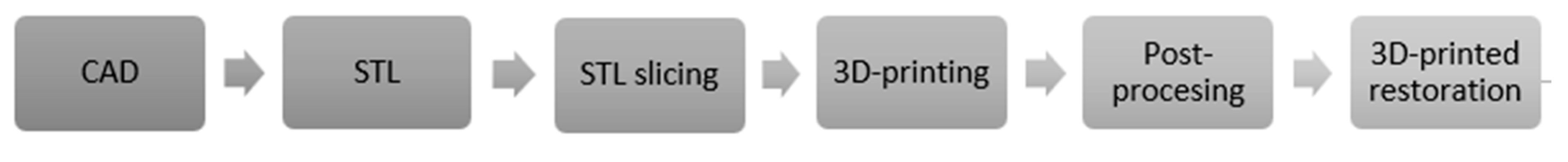
For prosthetic restoration 3D-printing, several steps are involved. Using CAD software, the external or internal geometry of the restoration is designed in an unordered set of planar triangles. The CAD software generates a standard tessellation language (STL) file. The STL file consists of three vertices (namely, X, Y, and Z coordinates) and an index that describes the orientation of the restoration. After this step, the designed restoration is mathematically sliced into layers with a plane parallel to the horizontal plane and sent to a 3D printer. The 3D-printing process starts by fabricating support structures and then each layer is printed according to the given layer thickness, and then bonded to the preceding layer until the restoration is completed [25]. 3D-printed restorations often require additional hardening, cleaning, and finishing procedures, known as a post-processing step. Restorations in this step are relatively unstable and have supporting structures that must be removed [26]. An overview of the 3D-printing steps is illustrated in Figure 3.
Despite continual advancements in 3D printing technology, determining whether it can compete with other digital dental manufacturing technologies remains difficult. The accuracy of the fabricated restorations is important for a technology to gain widespread acceptance. Several challenges have to be addressed, including limited validation of available materials, mechanical and thermal characteristics of existing materials that need to be improved, 3D-printing of ceramic structures, questionable accuracy, post-processing step that is often required, support structure material that cannot be recycled, material cost, good orientation angle that cannot be established, and lack of skilled designers in 3D-printing technologies [27].
In vitro studies gave promising results regarding the accuracy of some types of resin-based 3D-printed dental restorations [28,29], while other studies found that they were inaccurate to be clinically accepted and further investigations were essential [30,31,32]. Furthermore, the behavior of different types of polymer-based materials remains in the literature remains insufficient. Therefore, the aim of this in vitro study is to evaluate the accuracy of 3D-printed FDPs; namely, veneers, incisors, molars, and four-unit FDPs using two different 3D-printing technologies and polymer-based materials. The working hypothesis of this study is that the 3D-printed FDPs will provide similar accuracy values in terms of trueness and precision when compared to the original STL data.
Figure 1.
Additive manufacturing technologies classification. (According to ISO 52900:2015 [29]).
Figure 1.
Additive manufacturing technologies classification. (According to ISO 52900:2015 [29]).
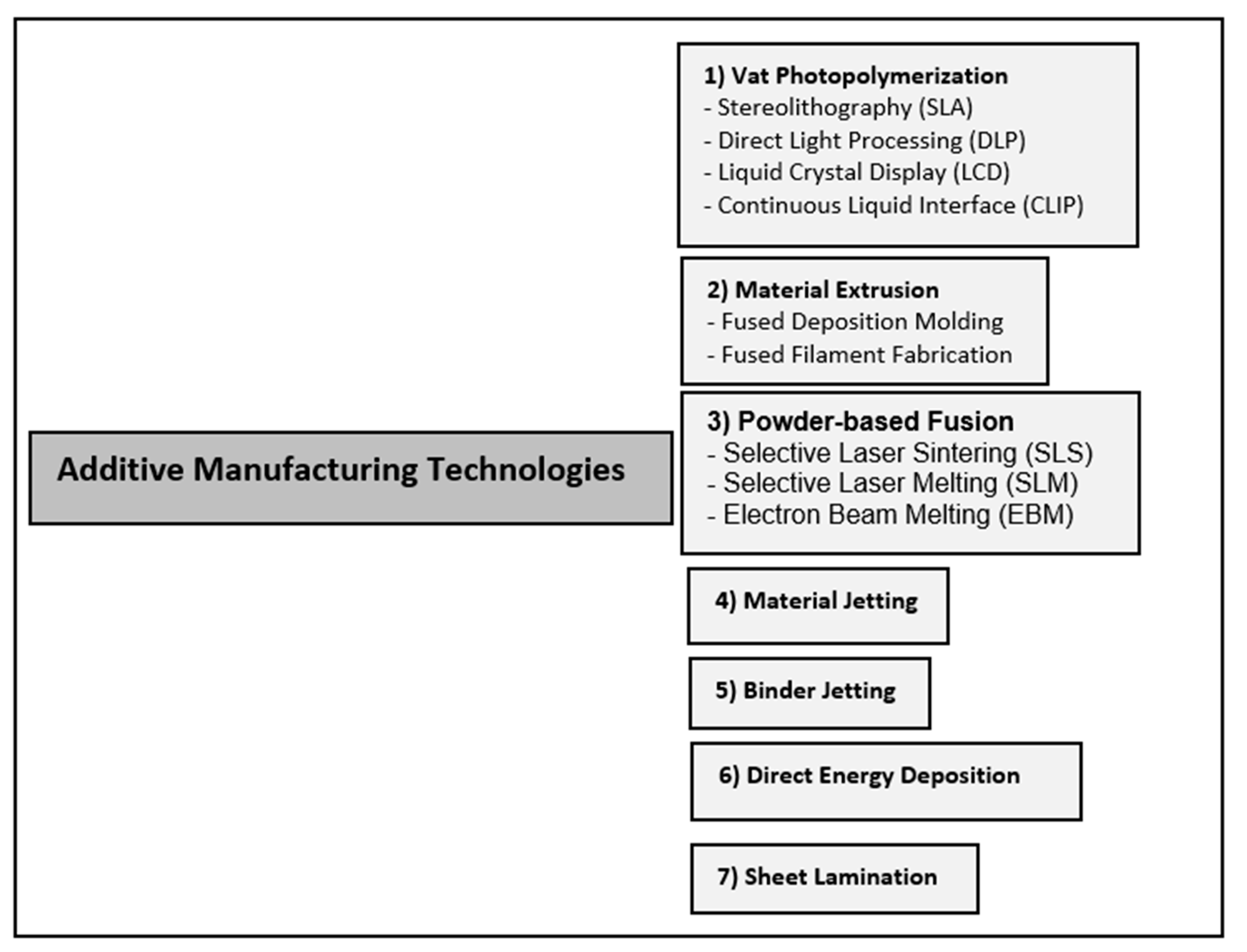
Figure 2.
Slicing a 3D CAD model into two-dimensional planar layers.
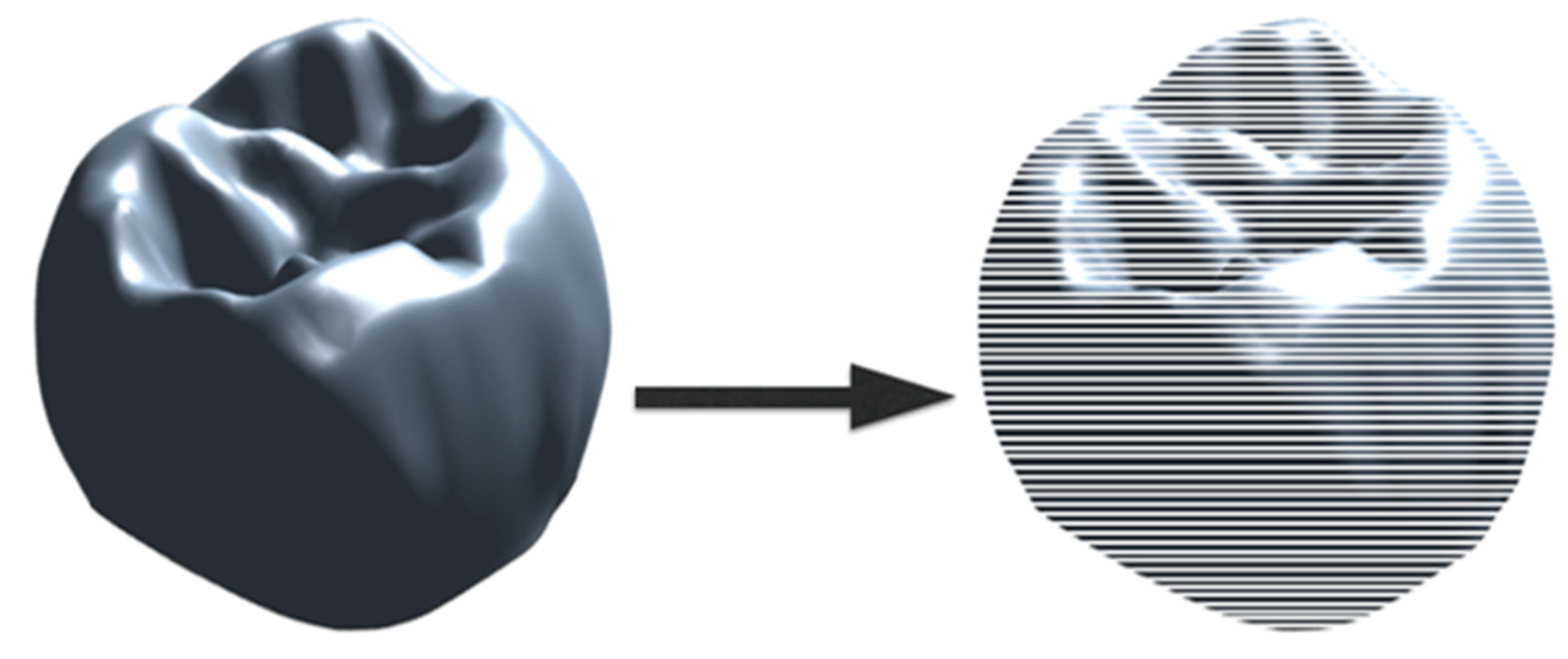
Figure 3.
3D-printing steps of a prosthetic restoration.
2. Material and methods
2.13. D-Printing Process
For FDPs 3D-printing, a partially edentulous maxillary and a fully dentulous mandibular typodont (Kavo basic study model, Kavo dental GmbH, Biberbach, Germany) were utilized to create two representative reference models. Reference models were created using a polyurethane material (Alpha-Pur, Shore A70, CTH Bezema R. Beitlich GmbH; Tübingen; Germany). One abutment tooth (a maxillary canine) was prepared to receive a veneer, one abutment tooth (a maxillary first incisor) was prepared to receive a full crown, and two abutments (a maxillary first premolar and a second molar) were prepared to receive a single-span four-unit FDP. A computer-aided impression (CAI) was taken with the 3MTM True Definition Scanner (software version 4.0.3.1, 3M ESPE, St. Paul, MN, USA). This intra-oral scanner (IOS) requires a scanning powder; the applied high-resolution 3MTM scanning powder spray (3M ESPE, St. Paul, MN, USA) consists of titanium dioxide, amorphous silica, aluminum hydroxide, and synthetic amorphous silica (Figure 4).
The size of the scanning powder particles is given as approximately 20 µm (manufacturer information). STL files were created after the scanning process and were utilized to fabricate the virtual fixed dental restorations using the CAD software (Zirkonzahn. Modellier 2015.10, Gais, Italy) (Figure 5).
Two 3D-printing technologies were utilized. For the DLP technology, the SHERAeco-print 30 (SHERA Werkstoff-Technologie GmbH & Co. KG, Lemförde, Germany) was utilized. Support structures were first created along the occlusal/incisal and the buccal/labial surfaces of the virtual designed restorations with a 30-angle (Figure 6).
The restorations were sliced into layers and sent to the 3D printer to start the printing process. A light-cured 3D-printing resin shade A3 (SHERAprint-cb, SHERA Werkstoff-Technologie GmbH & Co. KG, Lemförde, Germany)
3D-printed the provisional FDPs with a layer thickness of 50 µm using LED light. The printing process of tooth took one hour (Figure 7).
For the SLA technology, the Formlabs Form 2 (Formlabs, Boston, USA) was utilized. Support structures were created along the occlusal/incisal and the buccal/labial surface of the virtual designed restorations with 450 angle (Figure 8). The restorations were sliced into layers and sent to the 3D printer to start the 3D printing process. A light-cured castable resin 3D-printed the FDPs with a layer thickness of 25 µm using an ultraviolet laser with a laser power of 250 mW. The printing process took 8 hours and 18 minutes (Figure 9).
After the 3D printing for both 3D printers was completed, all restorations were ultrasonically cleaned with 96% alcohol and post-cured using an ultraviolet curing unit (Figure 10). Before performing further analyses, all restorations were visually inspected to ensure that they were free from any voids, defects, or surface roughness. The support structures were removed, and restorations were carefully polished (Figure 11).
2.2. Data Analysis
Each 3D printer technology generated 10 specimens of each type of restoration for a total of 80 restorations. These generated physical restorations were scanned again and digitized with the same IOS for evaluation. The accuracy of the 3D-printed restorations was evaluated using the Geomagic Qualify 2012 (Geomagic, Morrisville, NC, USA). The STL files of the originally designed restorations (CAD) and the STL files of the 3D-printed restorations were imported to the Geomagic software. The digital datasets obtained for each of the restorations were aligned and superimposed using the best-fit algorithm method to measure the discrepancies. The best-fit algorithm moves the test object to the reference object using an iterative closest-point algorithm (ICP); this step was performed automatically. Distributions of the discrepancies were presented as color-coded maps with 21 color segments. The range of maximum and minimum nominal values was set at ± 20 µm and the maximum and minimum critical values were set at ± 200 µm. Yellow to red color illustrates that the tested restoration is larger than the reference restoration (positive values). Turquoise-to-blue color illustrates that the tested restoration is smaller than the reference model (negative values).
Two parameters were evaluated to describe the accuracy of the restorations: trueness and precision. Trueness is the value by which the measured result deviates from the true size of the object. In this in vitro study, the trueness value was defined as the deviation from the originally designed CAD restorations. Precision refers to the variability of values generated from the scanned objects. In this in vitro study, the precision value was defined as the variation of deviations generated among the 3D-printed FDPs.
The statistical analysis of each restoration is represented by the overall evaluation concerning the external dimensional analysis of the labial surfaces of the veneers, labial and palatal surfaces of the incisors, occlusal surfaces of the molars, and the FPDs as well as the internal dimensional analysis that are represented as the copings of the FDPs (Figure 12). The analysis was performed using the statistical software (Minitab 16 Version 16.1.1, Minitab Inc., USA). One-way ANOVA and a two-sample T-test were used to test the overall trueness. A “two variances” test was performed to evaluate the differences in precision. A level of statistical significance (p-value < 0.05) was set.
3. Results
Table 2 summarizes the overall trueness values of the external and internal dimensional analysis of the 3D-printed FDPs. Positive values indicate that the 3D-printed FDPs are larger than the reference CAD design and negative values indicate that the 3D-printed FDPs are smaller than the reference CAD design. Regarding the external dimensional analysis of the incisors, it was found significant differences in the trueness (p-Value ≦ 0.001). On the labial surfaces, castable resin-based incisors showed a trueness of -97± 84 µm and provisional resin-based incisors showed a trueness value of -77± 98 µm (Figure 13b).
Furthermore, significant differences in the trueness of the occlusal status of molars were found (p-Value = 0.002). Provisional resin-based molars showed high trueness values of 77 ± 42 µm. Also in the FPDs, significant statistical differences of the occlusal status were found in the trueness (p-Value = 0.004). The provisional resin-based showed high trueness values of 214 ± 89 µm. The trueness in veneers did not show significant differences (p-Value= 0.854) (Figure 13c,d).
Copings of the incisors, molars, and four-unit FDPs were statistically significantly different in trueness with a p-value < 0.05. Provisional resin-based showed high trueness values of 52 ± 20 µm. On the other hand, no statistical differences in the trueness values in the veneers with a p-Value= 0.909 (Figure 14 a, b, c & d).
Table 3 summarizes the overall precision values of the external and internal dimensional analysis of the 3D-printed FDPs. Marginal statistical significance in the precision of the external dimensional analysis of the veneers was found (p-Value= 0.054). Furthermore, statistically significant differences in the precision of the molars occlusally were found (p-Value ≦ 0.001). High variability between the 3D-printed molars of the provisional resin-based ranging between -32- 188 µm (lower and upper control limits) was found (Figure 15 c). However, in the coping analysis no statistical differences in the precision of the molars were found (p-Value= 0.305) (Figure 16 c). Copings of the veneers, incisors, and retainers of the FPDs showed statistically significant differences in the precision p-Value= 0.002, ≦0.001, and 0.012, respectively. Copings of the castable resin-based incisors showed higher variability ranging between 0.5- 36 µm (lower and upper control limits) while copings of the provisional resin-based incisors showed higher variability ranging between 1-11 µm (lower and upper control limits) (Figure 16 b).
4. Discussion
Layer-by-layer is the conceptual method for fabricating 3D-printed dental restorations. This in vitro study investigated the accuracy of different types of resin-based 3D-printed FDPs. The working hypothesis of this investigation was partially rejected, as the generated restorations by either 3D-prinetrs did not show ideal clinical level of accuracy. The number of studies investigating the accuracy of 3D-printed fixed dental restorations in the literature is increasing [30,33,34,35,36]. The rationale for using this technology is to create an alternate valid method for fabrication that can replace or be compatible with subtractive and conventional fabrication processes.
Digitizing or data acquisition of reference models using IOS was the first step of the digital workflow in this investigation. The accuracy of this process directly influences the adaptation and fit of various types of dental restorations [37]. It was concluded that IOS can produce accurate FDPs in partially edentulous arches [38]. The IOS used in this present study is the True Definition Scanner. Currently, this IOS is commercially not available in the market. It is a video-based system that captures the desired intra-oral surfaces in a continuous series of images, which in turn increases the accuracy of the captured data[39,40]. Previous and recent studies reported its accuracy for single, partial and full arch scanning [41,42,43,44,45].
SLA and DLP 3D printing technologies are the most widely used technologies in fabricating FDPs [46]. Both of them are categorized as polymer-based, but the main differences between them are the materials used and the technique of building the layers. SLA was the first commercially available system introduced to the market as it offers the highest levels of accuracy, smooth surface finish, and good chemical bonding between layers [47,48]. The main drawbacks are limited longevity and low flexural strength [34]. DLP is faster than SLA in the fabrication and wastes less material, which reduces the cost [21]. In this in vitro study polymer-based materials provided from both 3D-printer manufacturers were used. Since, using the material provided by the same 3D printer manufacturer enhances production accuracy [29,47].
The internal dimensional analysis showed that the trueness of all types of the tested FDPs for both 3d-printing technologies are within the ideal clinical level of acceptance ranging between 17-52 µm (Table 2). Internal dimensional or coping analysis can be also evaluated by measuring the marginal gap width or the absolute marginal discrepancy [49]. This in vitro study evaluated the trueness and precision of the copings of all types of 3D-printed FDPs through the 3D software Geomagic (Qualify 2012). Here, the intaglio surfaces of the reference CAD models and the tested FDPs were marked, removed, fitted together through the best-fit algorithm step then 3D compared (Figure 17 and Figure 18).
This method is simple to manipulate and takes less time since each FDP was analyzed for the external and internal dimensional changes of the FDPs at the same time. However, this method did not analyze the accuracy of the internal fit of the restorations on the reference physical models. The accuracy was measured virtually according to the CAD reference model. Therefore, the coping analysis values may involve some technical errors related to the best-fit algorithm and the 3D compare steps.
Ideal marginal fit is the key criterion for the success of FDPs. Discrepancies in the marginal fit lead to adherence of oral bacteria, which contributes to plaque accumulation, secondary carries, cement microleakage, and endodontic inflammations [50]. A diversity of values and tested methodologies were published in the literature to access the maximum clinically accepted values. These values ranged between 50-150 µm [51,52,53]. In a systematic review, it was found that 3D-printed FDPs fabricated from polymer-based materials have superior marginal fit and internal adaptation and can be used as an alternative and valid fabrication method[36]. However, great variability in precision was detected between the 3d-printed FDPs, indicating that the reproducibility of both printers is negligible (Table 3 & Figure 16).
Concerning the external dimensional accuracy, the overall trueness values found that the occlusal surfaces of the four-unit FDPs ranged between 181 ± 91 µm (cast patterns) and 214 ± 89 µm (Provisionals) (table 2). Also, trueness values of the occlusal surfaces of the molars ranged between 53 ± 19 µm (cast patterns) and 77 ± 42 µm (Provisionals). Clinically, those restorations cannot be further processed and cemented without additional occlusal chairside adjustments. Some in vitro studies showed disparities in the external dimensional accuracy of 3D-printed four-unit FDPs, these were either larger or smaller than the CAD model [54,55]. Furthermore, it was shown that the post-curing step might influence the increase in dimensional accuracy [56].
Both 3D-printed cast patterns and provisional restorations of the incisors showed significant differences (Table 2). The observed deviations on the buccal surfaces were in negative values ranging between -97 ± 84 µm (Cast patterns) and -77 ± 98 µm (Provisionals). This is represented in the color-coded scales by the turquoise to dark blue areas, which indicated that the printed restorations were smaller than the reference model or in other words a shrinkage of the printed parts occurred (Figure 19 and Figure 20). However, these deviations can either be related to the tooth shape (morphology of the incisors), as well as to the technical sensitivity of the best fit-algorithm procedure [57]. And can be considered as high (Table 2).
It was proven that SLA technology provides better dimensional accuracy over other 3D-printing technologies [58], which was also observed in this in vitro study. This might be due to the longer printing time that provides adequate polymerization of the 3D-printed parts[59]. However, other parameters might influence the accuracy of 3D printing. Build orientation angle and layer thickness are the most studied influential parameters reviewed in the literature [47,59,60,61,62]. Build angle is the orientation of the printed model concerning the printer build platform. As the build angle changes, the geometry of printed layers changes. This, in turn, changes the supporting relationship of a given print layer to its successively printed layers, affecting ultimately the print accuracy in that region [61,63,64]. Studies have shown that 300 and 450 build angle orientations provide acceptable dimensional accuracy and surface finish [61,62], [60,65]. Build orientation angles in this in vitro study were chosen according to the literature reviews and 3d-printer manufacturers’ recommendations [58,66,67]. Layer thickness represents the height of each layer of the 3D-printed material regardless of the technology utilized. Layers are built along the Z coordinate and known as Z-axis resolution [64]. In general, the effect of layer thickness on the print accuracy depends on the 3D printing technology and the geometrical complexity of the dental restoration [68]. Controversial results were found in the literature regarding the effect of layer thickness on accuracy. Studies recommended setting high layer thickness in the range of 100 µm [69,70,71], while others found that lower layer thickness ranging between 25 and 50 µm provided more accurate dental restorations [66,68,72,73]. It was also found that the quality of 3D-printed FDPs with the 100 µm layer thickness was similar to that of the 50 µm layer thickness [60].
Other parameters that might also influence the accuracy, such as the printing mode, materials available, and the lack of standardization of the printing technologies. In general, in vitro studies do not always represent the actual clinical situation and the application of AM technologies remains still limited. Promising results show that it is possible to obtain a comparable accuracy as manufactured by the milling when the FDPs are manufactured by 3D printing with favorable parameters [60,74]. Therefore, investigations are required to improve the accuracy of the 3D-printed FDPs.
5. Conclusions
3D printing technology can be considered as a valid fabrication method. External and internal dimensional accuracy of the FPDs in this investigation in terms of trueness can be clinically accepted after chairside modifications. However significant variability between the 3D-printed FDPs was observed.
References
- Ahmed, K. E. We're going digital: the current state of CAD/CAM dentistry in prosthodontics. Primary Dental Journal 2018, 7, 30–35. [Google Scholar] [CrossRef]
- Barenghi, L.; Barenghi, A.; Garagiola, U.; Di Blasio, A.; Giannì, A. B.; Spadari, F. Pros and cons of CAD/CAM technology for infection prevention in dental settings during COVID-19 outbreak. Sensors 2021, 22, 49. [Google Scholar] [CrossRef]
- Suese, K. Progress in digital dentistry: The practical use of intraoral scanners. Dental Materials Journal 2020, 39, 52–56. [Google Scholar] [CrossRef]
- Morris, R. S.; Hoye, L. N.; Elnagar, M. H.; Atsawasuwan, P.; Galang-Boquiren, M. T.; Caplin, J.; Viana, G. C.; Obrez, A.; Kusnoto, B. Accuracy of Dental Monitoring 3D digital dental models using photograph and video mode. American Journal of Orthodontics and Dentofacial Orthopedics 2019, 156, 420–428. [Google Scholar] [CrossRef]
- Miyazaki, T.; Hotta, Y.; Kunii, J.; Kuriyama, S.; Tamaki, Y. A review of dental CAD/CAM: current status and future perspectives from 20 years of experience. Dental materials journal 2009, 28, 44–56. [Google Scholar] [CrossRef]
- Ferro, K. J.; Morgano, S. M.; Driscoll, C. F.; Freilich, M. A.; Guckes, A. D.; Knoernschild, K. L.; McGarry, T. J.; Twain, M. The glossary of prosthodontic terms. 2017.
- Beuer, F.; Schweiger, J.; Edelhoff, D. Digital dentistry: an overview of recent developments for CAD/CAM generated restorations. British dental journal 2008, 204, 505–511. [Google Scholar] [CrossRef]
- Schweiger, J.; Edelhoff, D.; Güth, J.-F. 3D printing in digital prosthetic dentistry: an overview of recent developments in additive manufacturing. Journal of Clinical Medicine 2021, 10, 2010. [Google Scholar] [CrossRef]
- Van Noort, R. The future of dental devices is digital. Dental materials 2012, 28, 3–12. [Google Scholar] [CrossRef]
- Joerg, R. Computer-aided design and fabrication of dental restorations. Journal of American dental association 2006, 137, 1289–1296. [Google Scholar]
- Kikuchi, M. The use of cutting temperature to evaluate the machinability of titanium alloys. Acta biomaterialia 2009, 5, 770–775. [Google Scholar] [CrossRef] [PubMed]
- Samra, A. P. B.; Morais, E.; Mazur, R. F.; Vieira, S. R.; Rached, R. N. CAD/CAM in dentistry–a critical review. Revista Odonto Ciência 2016, 31, 140–144. [Google Scholar] [CrossRef]
- Braian, M.; Jönsson, D.; Kevci, M.; Wennerberg, A. Geometrical accuracy of metallic objects produced with additive or subtractive manufacturing: A comparative in vitro study. Dental Materials 2018, 34, 978–993. [Google Scholar] [CrossRef] [PubMed]
- Glossary of Digital Dental Terms. 2nd Edition. Journal of Prosthodontics 2021, 30, 172–181.
- Torii, M.; Nakata, T.; Takahashi, K.; Kawamura, N.; Shimpo, H.; Ohkubo, C. Fitness and retentive force of cobalt-chromium alloy clasps fabricated with repeated laser sintering and milling. journal of prosthodontic research 2018, 62, 342–346. [Google Scholar] [CrossRef]
- Nakata, T.; Shimpo, H.; Ohkubo, C. Clasp fabrication using one-process molding by repeated laser sintering and high-speed milling. Journal of prosthodontic research 2017, 61, 276–282. [Google Scholar] [CrossRef]
- Marquardt, T.; Zheng, E. History of 3D printing. 2016.
- Huang, Y.; Leu, M. C.; Mazumder, J.; Donmez, A. Additive manufacturing: current state, future potential, gaps and needs, and recommendations. Journal of Manufacturing Science and Engineering 2015, 137, 014001. [Google Scholar] [CrossRef]
- International organization for standardization. ISO/ASTM 52900:2015 (ASTM F2792). 2019.
- Kruth, J.-P.; Leu, M.-C.; Nakagawa, T. Progress in additive manufacturing and rapid prototyping. Cirp Annals 1998, 47, 525–540. [Google Scholar] [CrossRef]
- Revilla-León, M.; Özcan, M. Additive manufacturing technologies used for processing polymers: current status and potential application in prosthetic dentistry. Journal of Prosthodontics 2019, 28, 146–158. [Google Scholar] [CrossRef]
- Revilla-León, M.; Sadeghpour, M.; Özcan, M. An update on applications of 3D printing technologies used for processing polymers used in implant dentistry. Odontology 2020, 108, 331–338. [Google Scholar] [CrossRef]
- Revilla-León, M.; Meyer, M. J.; Özcan, M. Metal additive manufacturing technologies: literature review of current status and prosthodontic applications. Int. J. Comput. Dent 2019, 22, 55–67. [Google Scholar]
- Revilla-León, M.; Meyer, M. J.; Zandinejad, A.; Özcan, M. Additive manufacturing technologies for processing zirconia in dental applications. Int J Comput Dent 2020, 23, 27–37. [Google Scholar] [PubMed]
- Jacobs, P. F. Stereolithography and other RP&M technologies: from rapid prototyping to rapid tooling. Society of Manufacturing Engineers: 1995.
- Ian Gibson, I. G. Additive manufacturing technologies 3D printing, rapid prototyping, and direct digital manufacturing. Springer: 2015.
- Alammar, A.; Kois, J. C.; Revilla-León, M.; Att, W. Additive manufacturing technologies: current status and future perspectives. Journal of Prosthodontics 2022, 31, 4–12. [Google Scholar] [CrossRef] [PubMed]
- Alharbi, N.; Alharbi, S.; Cuijpers, V. M.; Osman, R. B.; Wismeijer, D. Three-dimensional evaluation of marginal and internal fit of 3D-printed interim restorations fabricated on different finish line designs. Journal of prosthodontic research 2018, 62, 218–226. [Google Scholar] [CrossRef] [PubMed]
- Tahayeri, A.; Morgan, M.; Fugolin, A. P.; Bompolaki, D.; Athirasala, A.; Pfeifer, C. S.; Ferracane, J. L.; Bertassoni, L. E. 3D printed versus conventionally cured provisional crown and bridge dental materials. Dental materials 2018, 34, 192–200. [Google Scholar] [CrossRef] [PubMed]
- Jang, Y.; Sim, J.-Y.; Park, J.-K.; Kim, W.-C.; Kim, H.-Y.; Kim, J.-H. Accuracy of 3-unit fixed dental prostheses fabricated on 3D-printed casts. The Journal of prosthetic dentistry 2020, 123, 135–142. [Google Scholar] [CrossRef] [PubMed]
- Rungrojwittayakul, O.; Kan, J. Y.; Shiozaki, K.; Swamidass, R. S.; Goodacre, B. J.; Goodacre, C. J.; Lozada, J. L. Accuracy of 3D printed models created by two technologies of printers with different designs of model base. Journal of Prosthodontics 2020, 29, 124–128. [Google Scholar] [CrossRef] [PubMed]
- Joda, T.; Matthisson, L.; Zitzmann, N. U. Impact of aging on the accuracy of 3D-printed dental models: an in vitro investigation. Journal of clinical medicine 2020, 9, 1436. [Google Scholar] [CrossRef] [PubMed]
- Pantea, M.; Ciocoiu, R. C.; Greabu, M.; Ripszky Totan, A.; Imre, M.; Țâncu, A. M. C.; Sfeatcu, R.; Spînu, T. C.; Ilinca, R.; Petre, A. E. Compressive and flexural strength of 3D-printed and conventional resins designated for interim fixed dental prostheses: An in vitro comparison. Materials 2022, 15, 3075. [Google Scholar] [CrossRef]
- Ellakany, P.; Fouda, S. M.; Mahrous, A. A.; AlGhamdi, M. A.; Aly, N. M. Influence of CAD/CAM milling and 3d-printing fabrication methods on the mechanical properties of 3-unit interim fixed dental prosthesis after thermo-mechanical aging process. Polymers 2022, 14, 4103. [Google Scholar] [CrossRef]
- Park, S.-M.; Park, J.-M.; Kim, S.-K.; Heo, S.-J.; Koak, J.-Y. Flexural strength of 3D-printing resin materials for provisional fixed dental prostheses. Materials 2020, 13, 3970. [Google Scholar] [CrossRef]
- Al Wadei, M. H. D.; Sayed, M. E.; Jain, S.; Aggarwal, A.; Alqarni, H.; Gupta, S. G.; Alqahtani, S. M.; Alahmari, N. M.; Alshehri, A. H.; Jain, M. Marginal Adaptation and Internal Fit of 3D-Printed Provisional Crowns and Fixed Dental Prosthesis Resins Compared to CAD/CAM-Milled and Conventional Provisional Resins: A Systematic Review and Meta-Analysis. Coatings 2022, 12, 1777. [Google Scholar] [CrossRef]
- Güth, J.-F.; Edelhoff, D.; Schweiger, J.; Keul, C. A new method for the evaluation of the accuracy of full-arch digital impressions in vitro. Clinical oral investigations 2016, 20, 1487–1494. [Google Scholar] [CrossRef]
- Kihara, H.; Hatakeyama, W.; Komine, F.; Takafuji, K.; Takahashi, T.; Yokota, J.; Oriso, K.; Kondo, H. Accuracy and practicality of intraoral scanner in dentistry: A literature review. Journal of prosthodontic research 2020, 64, 109–113. [Google Scholar] [CrossRef] [PubMed]
- Patzelt, S. B.; Bishti, S.; Stampf, S.; Att, W. Accuracy of computer-aided design/computer-aided manufacturing–generated dental casts based on intraoral scanner data. The Journal of the American Dental Association 2014, 145, 1133–1140. [Google Scholar] [CrossRef] [PubMed]
- Patzelt, S. B.; Emmanouilidi, A.; Stampf, S.; Strub, J. R.; Att, W. Accuracy of full-arch scans using intraoral scanners. Clinical oral investigations 2014, 18, 1687–1694. [Google Scholar] [CrossRef]
- Sacher, M.; Schulz, G.; Deyhle, H.; Jäger, K.; Müller, B. Accuracy of commercial intraoral scanners. Journal of Medical Imaging 2021, 8, 035501–035501. [Google Scholar] [CrossRef] [PubMed]
- Hack, G. D.; Patzelt, S. Evaluation of the accuracy of six intraoral scanning devices: an in-vitro investigation. ADA Prof Prod Rev 2015, 10, 1–5. [Google Scholar]
- Vandeweghe, S.; Vervack, V.; Dierens, M.; De Bruyn, H. Accuracy of digital impressions of multiple dental implants: an in vitro study. Clinical oral implants research 2017, 28, 648–653. [Google Scholar] [CrossRef]
- Pattamavilai, S.; Ongthiemsak, C. Accuracy of intraoral scanners in different complete arch scan patterns. The Journal of Prosthetic Dentistry 2022. [Google Scholar] [CrossRef]
- Amornvit, P.; Rokaya, D.; Sanohkan, S. Comparison of accuracy of current ten intraoral scanners. BioMed Research International 2021, 2021. [Google Scholar] [CrossRef]
- Della Bona, A.; Cantelli, V.; Britto, V. T.; Collares, K. F.; Stansbury, J. W. 3D printing restorative materials using a stereolithographic technique: A systematic review. Dental Materials 2021, 37, 336–350. [Google Scholar] [CrossRef]
- Alharbi, N.; Osman, R. B.; Wismeijer, D. Factors Influencing the Dimensional Accuracy of 3D-Printed Full-Coverage Dental Restorations Using Stereolithography Technology. The International journal of prosthodontics 2016, 29, 503–510. [Google Scholar] [CrossRef]
- Kim, G. B.; Lee, S.; Kim, H.; Yang, D. H.; Kim, Y.-H.; Kyung, Y. S.; Kim, C.-S.; Choi, S. H.; Kim, B. J.; Ha, H. Three-dimensional printing: basic principles and applications in medicine and radiology. Korean journal of radiology 2016, 17, 182–197. [Google Scholar] [CrossRef]
- Contrepois, M.; Soenen, A.; Bartala, M.; Laviole, O. Marginal adaptation of ceramic crowns: a systematic review. The Journal of prosthetic dentistry 2013, 110, 447–454.e10. [Google Scholar] [CrossRef]
- Petersen, R. C.; Liu, P.-R.; Reddy, M. S. An Advanced Fiber-Reinforced Composite Solution for Gingival Inflammation and Bone Loss Related to Restorative Crowns. EC dental science 2020, 19. [Google Scholar]
- Att, W.; Komine, F.; Gerds, T.; Strub, J. R. Marginal adaptation of three different zirconium dioxide three-unit fixed dental prostheses. The Journal of prosthetic dentistry 2009, 101, 239–247. [Google Scholar] [CrossRef]
- Al Rifaiy, M. Evaluation of vertical marginal adaptation of provisional crowns by digital microscope. Nigerian Journal of Clinical Practice 2017, 20, 1610–1617. [Google Scholar] [CrossRef]
- McLean, J. The estimation of cement film thickness by an in vivo technique. British dental journal 1971, 131, 107–111. [Google Scholar] [CrossRef]
- Dikova, T.; Dzhendov, D.; Katreva, I.; Pavlova, D. Accuracy of polymeric dental bridges manufactured by stereolithography. Arch Mater Sci Eng 2016, 78, 29–36. [Google Scholar] [CrossRef]
- Ishida, Y.; Miyasaka, T. Dimensional accuracy of dental casting patterns created by 3D printers. Dental materials journal 2016, 35, 250–256. [Google Scholar] [CrossRef] [PubMed]
- Song, G.; Son, J.-W.; Jang, J.-H.; Choi, S.-H.; Jang, W.-H.; Lee, B.-N.; Park, C. Comparing volumetric and biological aspects of 3D-printed interim restorations under various post-curing modes. The Journal of Advanced Prosthodontics 2021, 13, 71. [Google Scholar] [CrossRef]
- Koch, G. K.; Gallucci, G. O.; Lee, S. J. Accuracy in the digital workflow: from data acquisition to the digitally milled cast. The Journal of prosthetic dentistry 2016, 115, 749–754. [Google Scholar] [CrossRef] [PubMed]
- Badanova, N.; Perveen, A.; Talamona, D. Study of SLA Printing Parameters Affecting the Dimensional Accuracy of the Pattern and Casting in Rapid Investment Casting. Journal of Manufacturing and Materials Processing 2022, 6, 109. [Google Scholar] [CrossRef]
- Arnold, C.; Monsees, D.; Hey, J.; Schweyen, R. Surface quality of 3D-printed models as a function of various printing parameters. Materials 2019, 12, 1970. [Google Scholar] [CrossRef]
- Park, G.-S.; Kim, S.-K.; Heo, S.-J.; Koak, J.-Y.; Seo, D.-G. Effects of printing parameters on the fit of implant-supported 3D printing resin prosthetics. Materials 2019, 12, 2533. [Google Scholar] [CrossRef]
- Unkovskiy, A.; Bui, P. H.-B.; Schille, C.; Geis-Gerstorfer, J.; Huettig, F.; Spintzyk, S. Objects build orientation, positioning, and curing influence dimensional accuracy and flexural properties of stereolithographically printed resin. Dental Materials 2018, 34, e324–e333. [Google Scholar] [CrossRef] [PubMed]
- Hada, T.; Kanazawa, M.; Iwaki, M.; Arakida, T.; Soeda, Y.; Katheng, A.; Otake, R.; Minakuchi, S. Effect of printing direction on the accuracy of 3D-printed dentures using stereolithography technology. Materials 2020, 13, 3405. [Google Scholar] [CrossRef]
- Alexander, P.; Allen, S.; Dutta, D. Part orientation and build cost determination in layered manufacturing. Computer-Aided Design 1998, 30, 343–356. [Google Scholar] [CrossRef]
- Ko, J.; Bloomstein, R. D.; Briss, D.; Holland, J. N.; Morsy, H. M.; Kasper, F. K.; Huang, W. Effect of build angle and layer height on the accuracy of 3-dimensional printed dental models. American Journal of Orthodontics and Dentofacial Orthopedics 2021, 160, 451–458.e2. [Google Scholar] [CrossRef]
- Park, S.-M.; Park, J.-M.; Kim, S.-K.; Heo, S.-J.; Koak, J.-Y. Comparison of flexural strength of three-dimensional printed three-unit provisional fixed dental prostheses according to build directions. Journal of Korean Dental Science 2019, 12, 13–19. [Google Scholar]
- Çakmak, G.; Cuellar, A. R.; Donmez, M. B.; Abou-Ayash, S.; Lu, W.-E.; Schimmel, M.; Yilmaz, B. Effect of printing layer thickness on the trueness of 3-unit interim fixed partial dentures. The journal of prosthetic dentistry 2022. [Google Scholar] [CrossRef]
- Kharat, S. S.; Tatikonda, A.; Raina, S.; Gubrellay, P.; Gupta, N.; Asopa, S. J. In vitro evaluation of the accuracy of seating cast metal fixed partial denture on the abutment teeth with varying degree of convergence angle. Journal of Clinical and Diagnostic Research: JCDR, 2015; 9, ZC56. [Google Scholar]
- Zhang, Z.-c.; Li, P.-l.; Chu, F.-t.; Shen, G. Influence of the three-dimensional printing technique and printing layer thickness on model accuracy. Journal of Orofacial Orthopedics/Fortschritte der Kieferorthopadie.
- You, S.-M.; You, S.-G.; Kang, S.-Y.; Bae, S.-Y.; Kim, J.-H. Evaluation of the accuracy (trueness and precision) of a maxillary trial denture according to the layer thickness: An in vitro study. The Journal of prosthetic dentistry 2021, 125, 139–145. [Google Scholar] [CrossRef]
- Alshamrani, A. A.; Raju, R.; Ellakwa, A. Effect of printing layer thickness and postprinting conditions on the flexural strength and hardness of a 3D-printed resin. BioMed Research International 2022, 2022. [Google Scholar] [CrossRef]
- Yilmaz, B.; Donmez, M. B.; Kahveci, Ç.; Cuellar, A. R.; de Paula, M. S.; Schimmel, M.; Abou-Ayash, S.; Çakmak, G. Effect of printing layer thickness on the trueness and fit of additively manufactured removable dies. The journal of prosthetic dentistry 2022, 128, 1318.e1–1318.e9. [Google Scholar] [CrossRef] [PubMed]
- Favero, C. S.; English, J. D.; Cozad, B. E.; Wirthlin, J. O.; Short, M. M.; Kasper, F. K. Effect of print layer height and printer type on the accuracy of 3-dimensional printed orthodontic models. American Journal of Orthodontics and Dentofacial Orthopedics 2017, 152, 557–565. [Google Scholar] [CrossRef] [PubMed]
- Kaleli, N.; Ural, Ç.; Özköylü, G.; Duran, İ. Effect of layer thickness on the marginal and internal adaptation of laser-sintered metal frameworks. The Journal of Prosthetic Dentistry 2019, 121, 922–928. [Google Scholar] [CrossRef] [PubMed]
- Karasan, D.; Legaz, J.; Boitelle, P.; Mojon, P.; Fehmer, V.; Sailer, I. Accuracy of Additively Manufactured and Milled Interim 3-Unit Fixed Dental Prostheses. Journal of Prosthodontics 2022, 31, 58–69. [Google Scholar] [CrossRef] [PubMed]
Figure 4.
a) Polyurethane reference jaw models; b) Volumetric information obtained by the True Definition IOS.
Figure 4.
a) Polyurethane reference jaw models; b) Volumetric information obtained by the True Definition IOS.
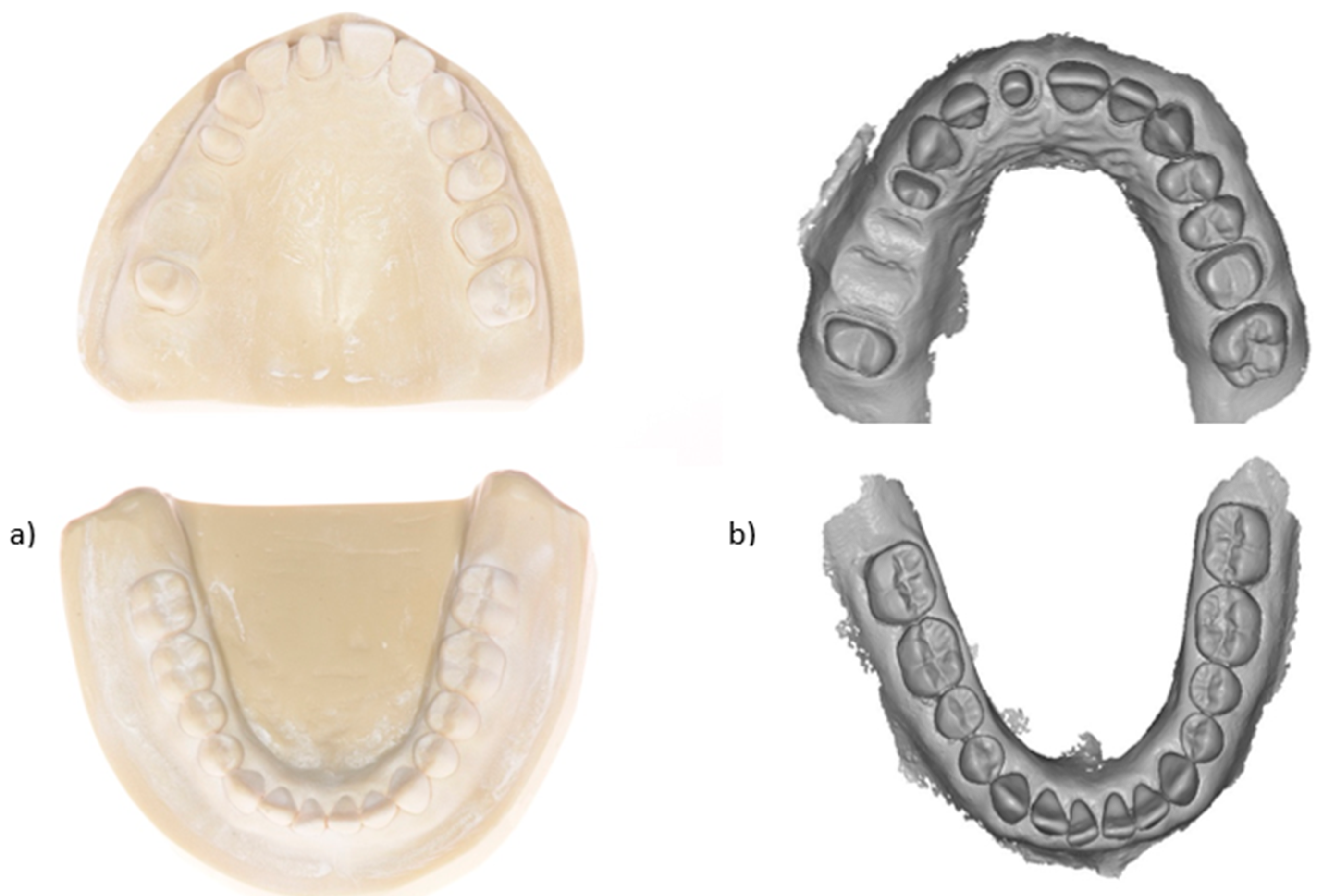
Figure 5.
CAD design of the prospective 3D-printed FDPs.

Figure 6.
Virtual orientation of the provisional FDPs on the virtual build platform.
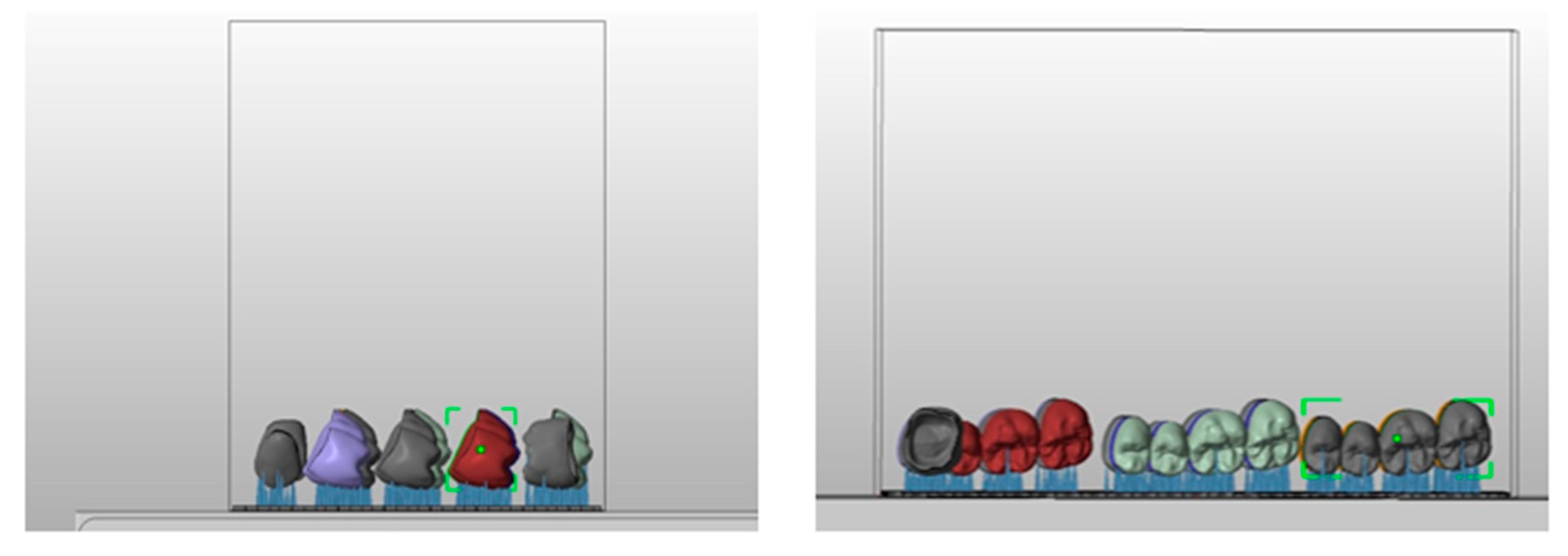
Figure 7.
3D-printed provisional FDPs.
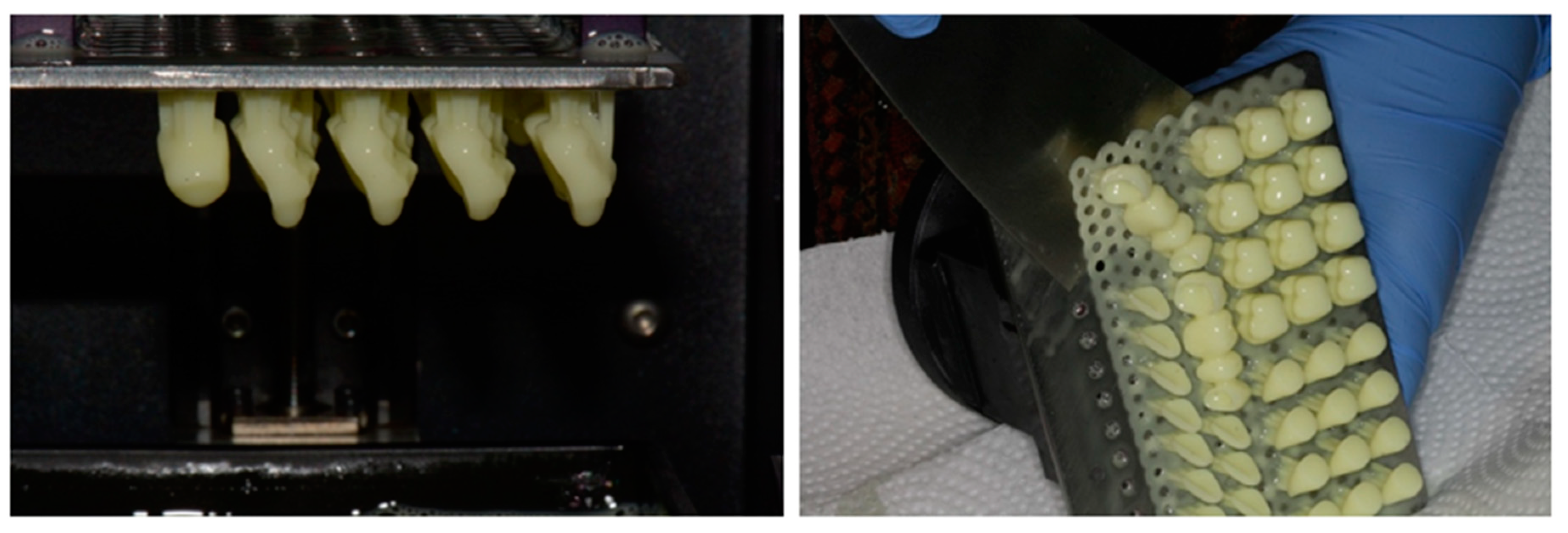
Figure 8.
Virtual orientation of the castable FDPs on the build platform.
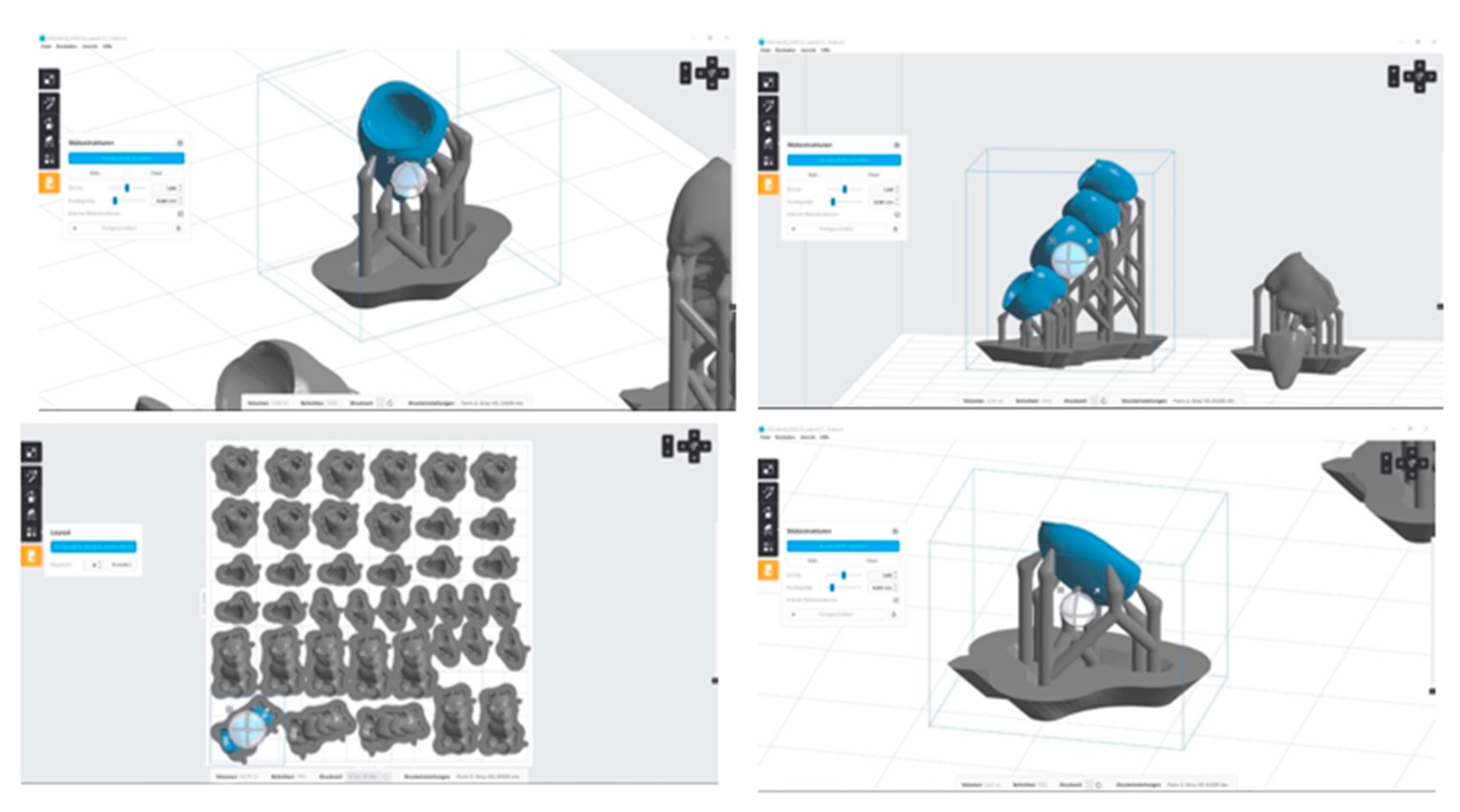
Figure 9.
3D-printed castable FDPs.
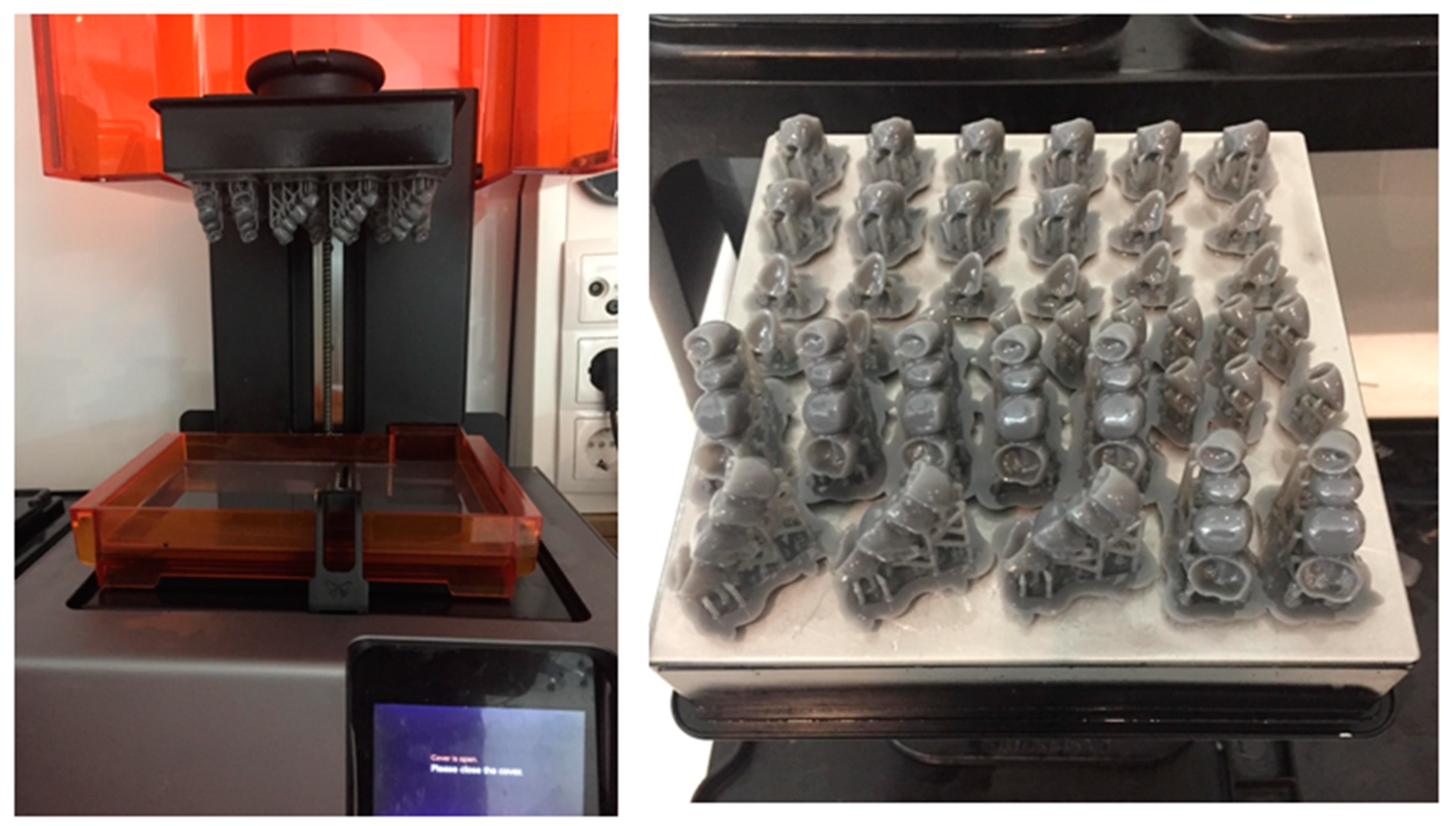
Figure 10.
Ultraviolet post-curing of the 3D-printed FDPs.
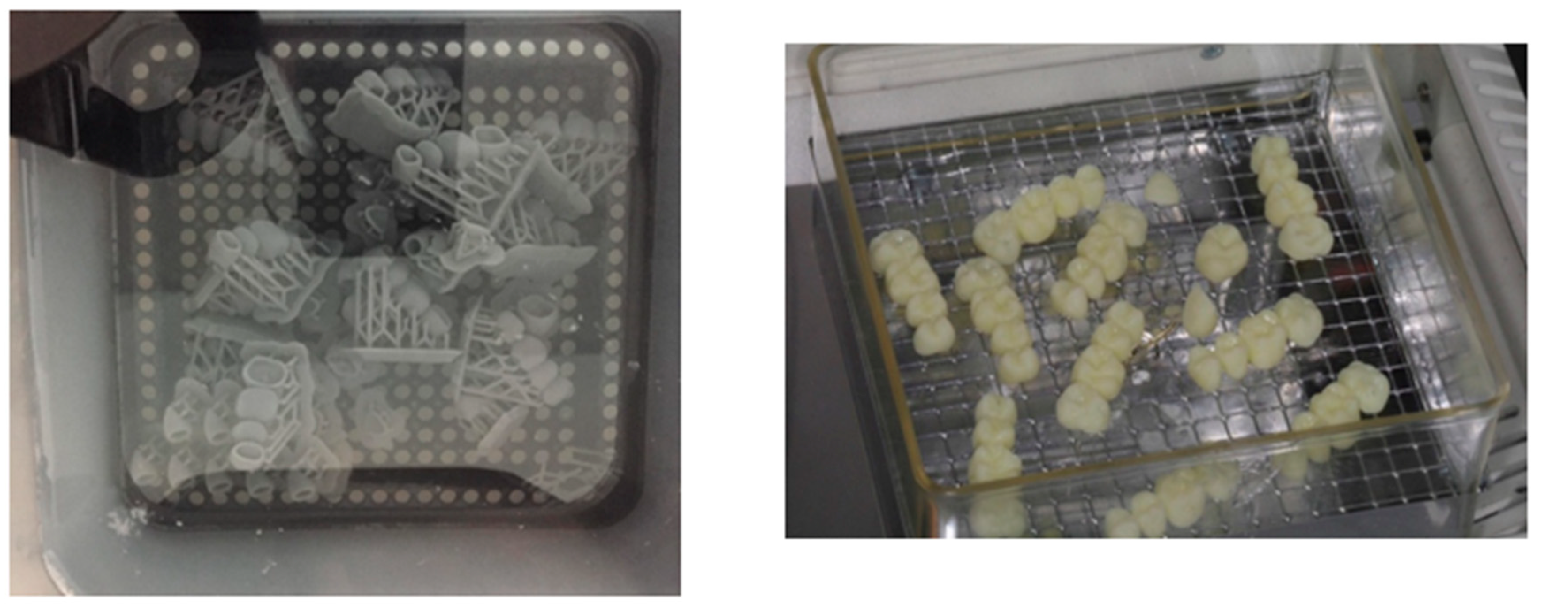
Figure 11.
3D-printed restorations after ultraviolet post-curing and support structures removal a) FDPs, b) molars, c) incisors, and d) veneers.
Figure 11.
3D-printed restorations after ultraviolet post-curing and support structures removal a) FDPs, b) molars, c) incisors, and d) veneers.
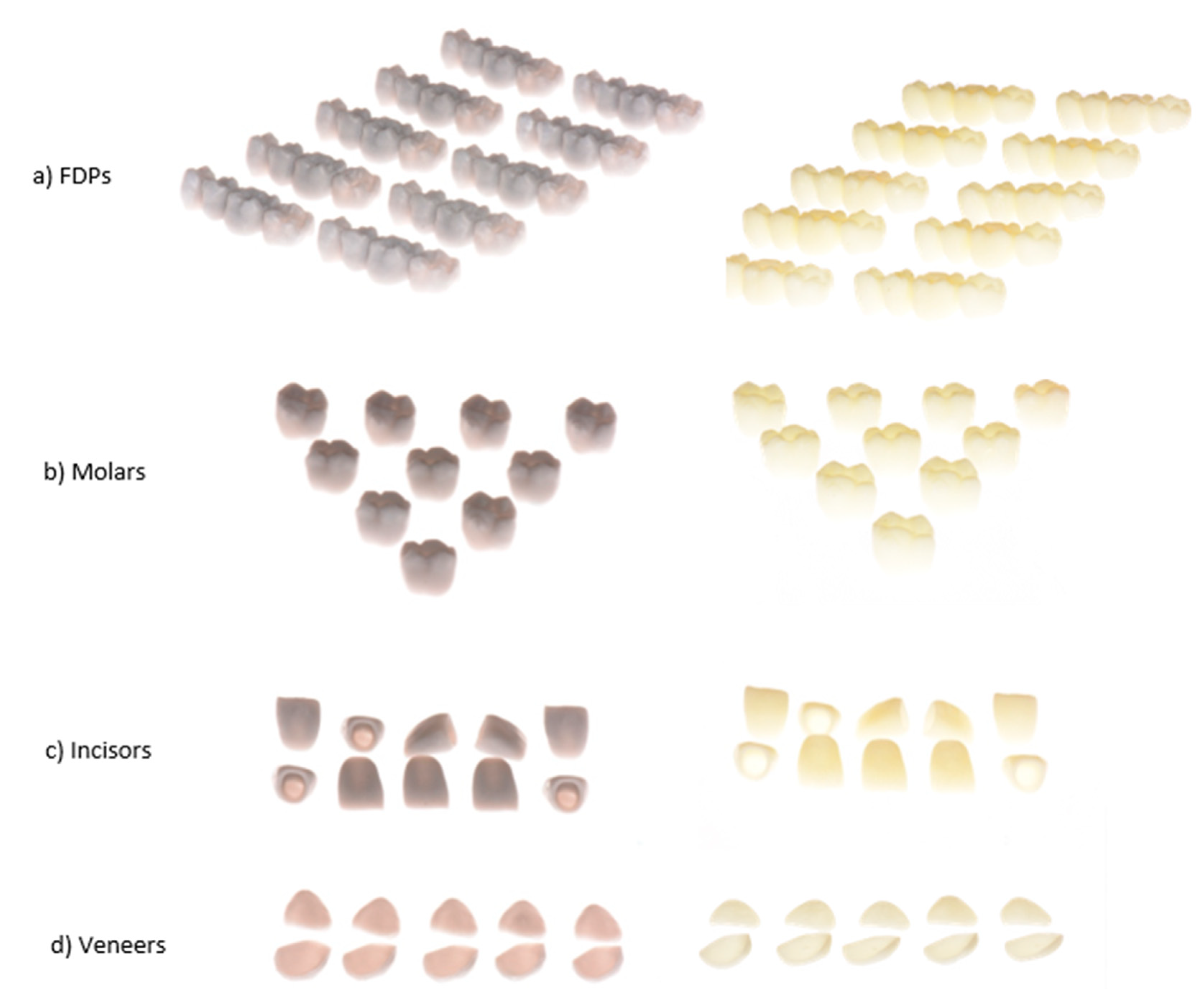
Figure 12.
Three dimensional analysis of the 3D-printed FDPs and copings using the Geomagic software (Qualify 2012).
Figure 12.
Three dimensional analysis of the 3D-printed FDPs and copings using the Geomagic software (Qualify 2012).
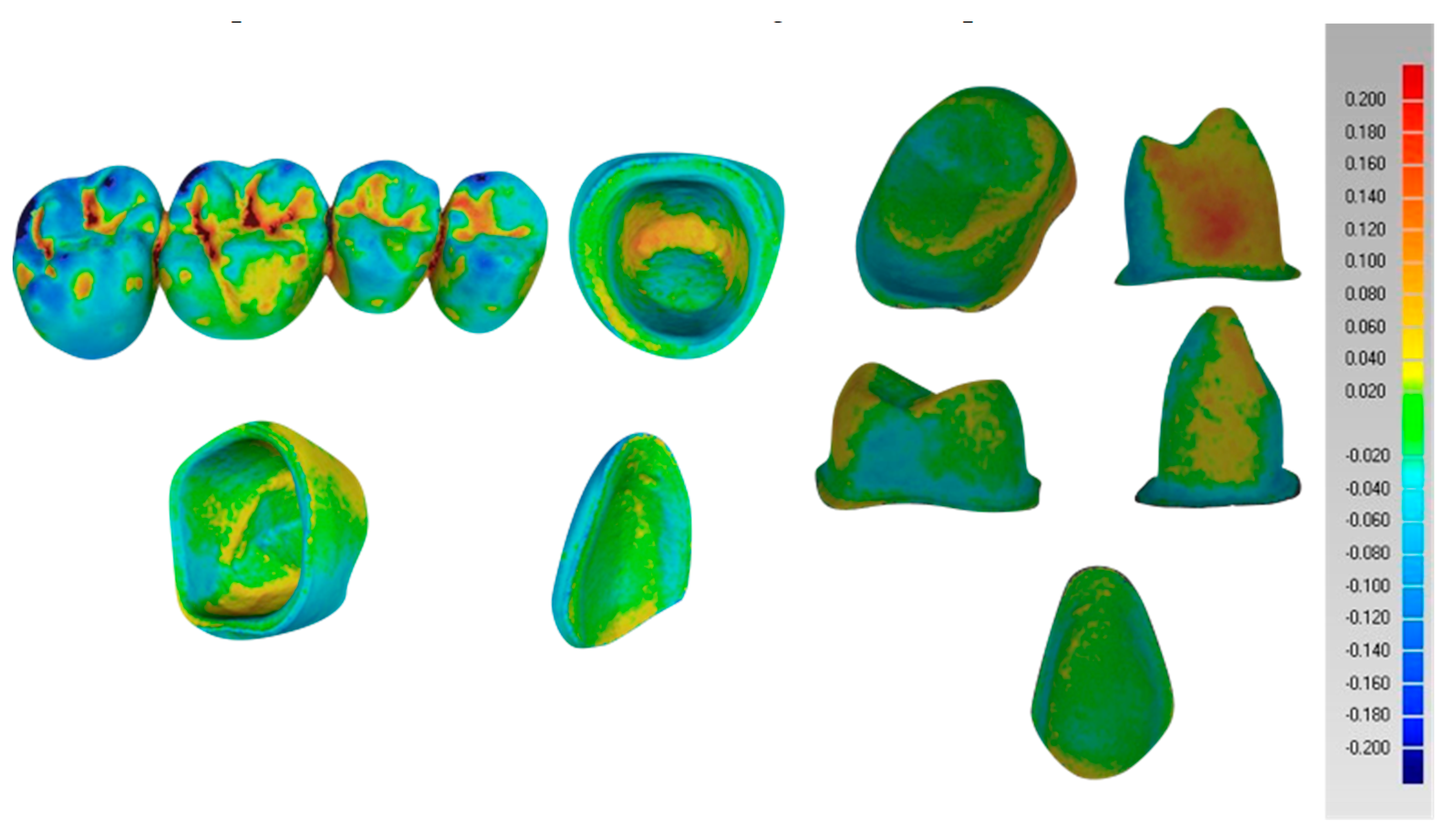
Figure 13.
Boxplots representing the trueness of the external dimensional changes of the 3D-printed FDPs a) veneers, b) incisors, c) molars d) retainers of the FDPs (in micrometers).*=outlier.
Figure 13.
Boxplots representing the trueness of the external dimensional changes of the 3D-printed FDPs a) veneers, b) incisors, c) molars d) retainers of the FDPs (in micrometers).*=outlier.
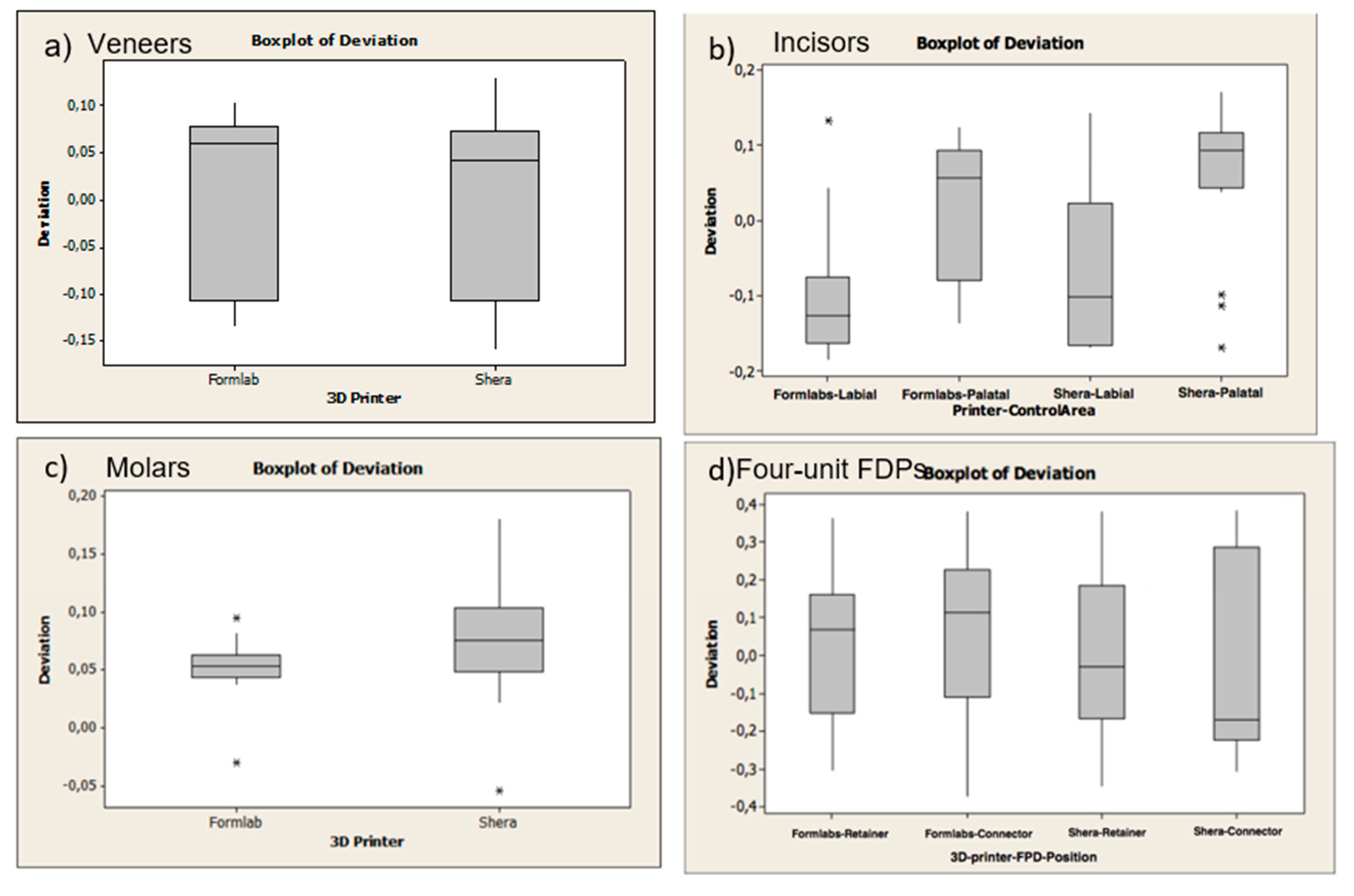
Figure 14.
Boxplots representing the trueness of the internal dimensional changes (copings) of the 3D-printed FDPs a) veneers, b) incisors, c) molars d) retainers of the four-unit FDPs (in micrometers). *=outlier.
Figure 14.
Boxplots representing the trueness of the internal dimensional changes (copings) of the 3D-printed FDPs a) veneers, b) incisors, c) molars d) retainers of the four-unit FDPs (in micrometers). *=outlier.
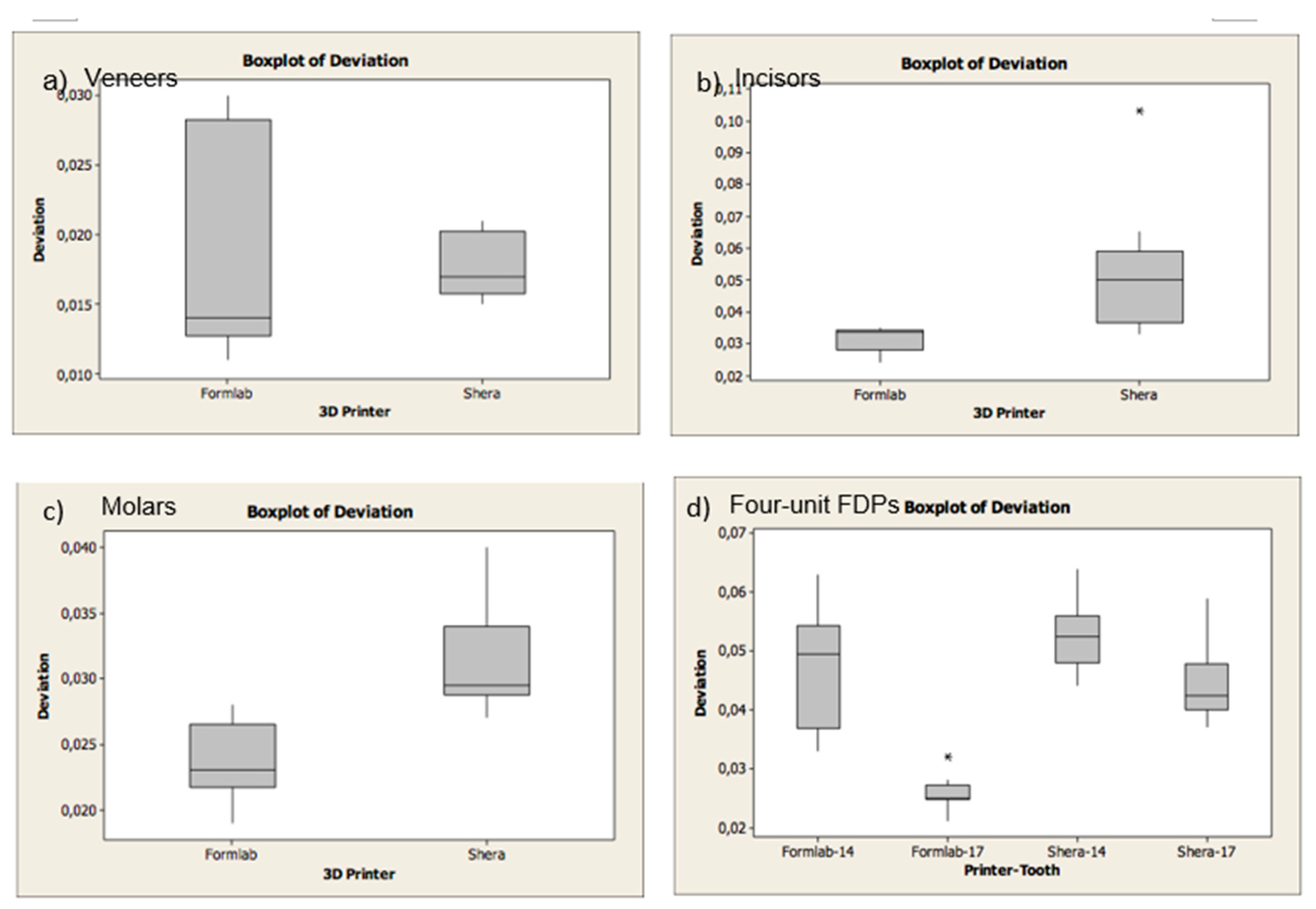
Figure 15.
Individual chart showing the precision of the external dimensional changes of the 3D-printed FDPs a) veneers, b) incisors, c) molars, d) four-unit FDPs (in micrometers). * LCL= Lower control limit; UCL: Upper control limit.
Figure 15.
Individual chart showing the precision of the external dimensional changes of the 3D-printed FDPs a) veneers, b) incisors, c) molars, d) four-unit FDPs (in micrometers). * LCL= Lower control limit; UCL: Upper control limit.
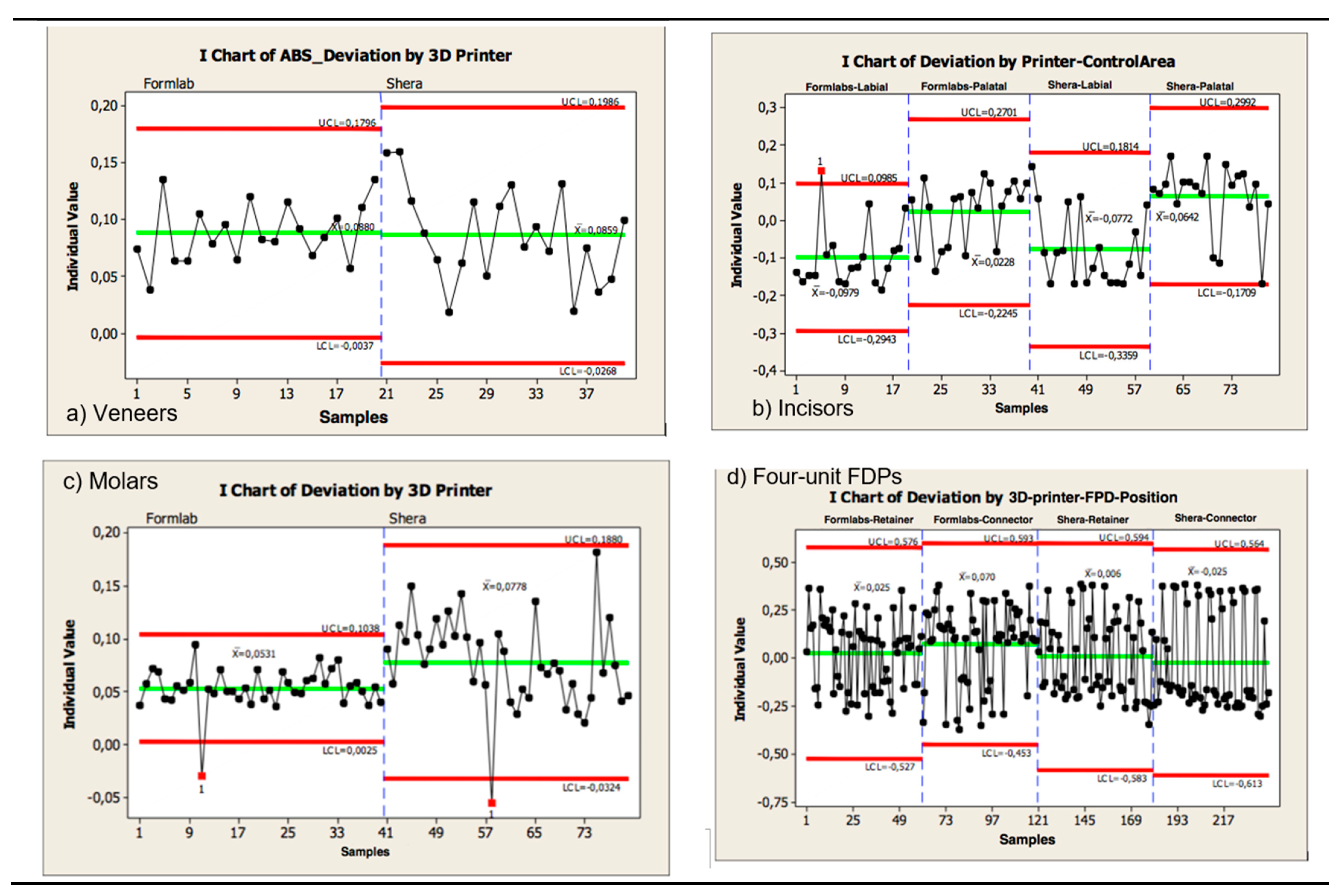
Figure 16.
Individual chart showing the precision of the internal dimensional changes (copings) of the 3D-printed FDPs a) Veneers, b) Incisors, c) Molars, d) Four-unit FDPs (in micrometers).
Figure 16.
Individual chart showing the precision of the internal dimensional changes (copings) of the 3D-printed FDPs a) Veneers, b) Incisors, c) Molars, d) Four-unit FDPs (in micrometers).
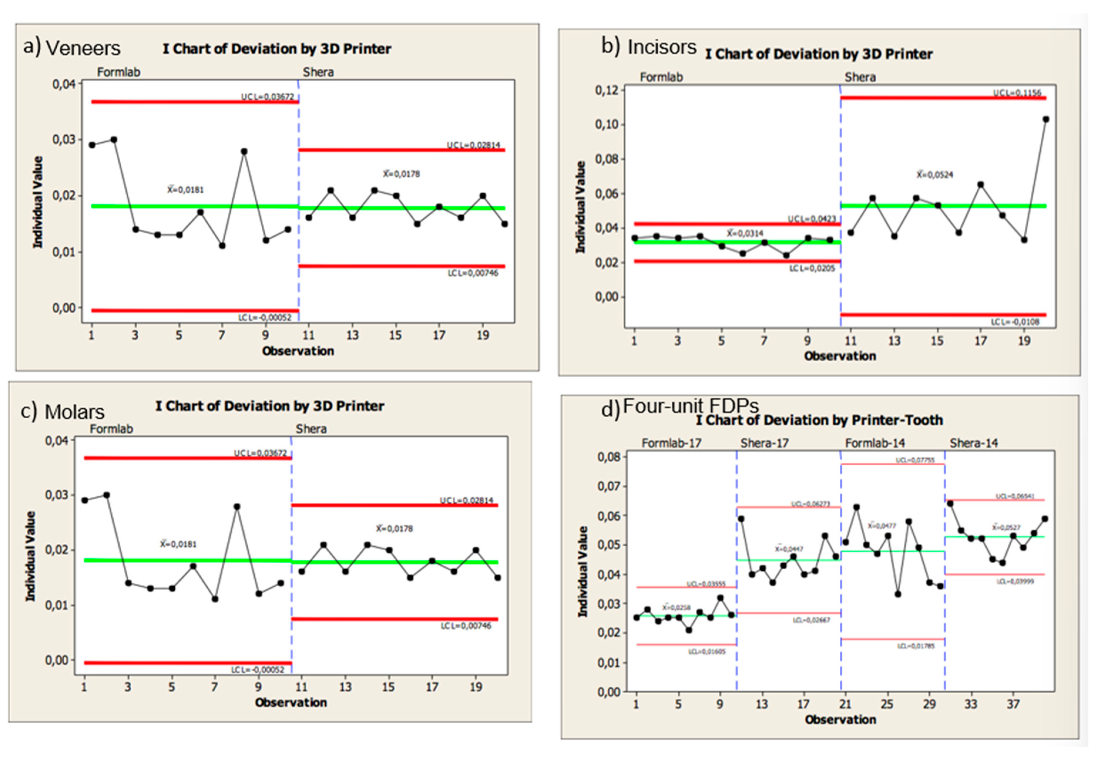
Figure 17.
A cross section of the superimposed CAD copings (purple lines) and the 3D-printed copings (black lines) demonstrated for the provisional FPDs; a) veneer, b) incisor, c) molar, and d) four-unit FPD.
Figure 17.
A cross section of the superimposed CAD copings (purple lines) and the 3D-printed copings (black lines) demonstrated for the provisional FPDs; a) veneer, b) incisor, c) molar, and d) four-unit FPD.
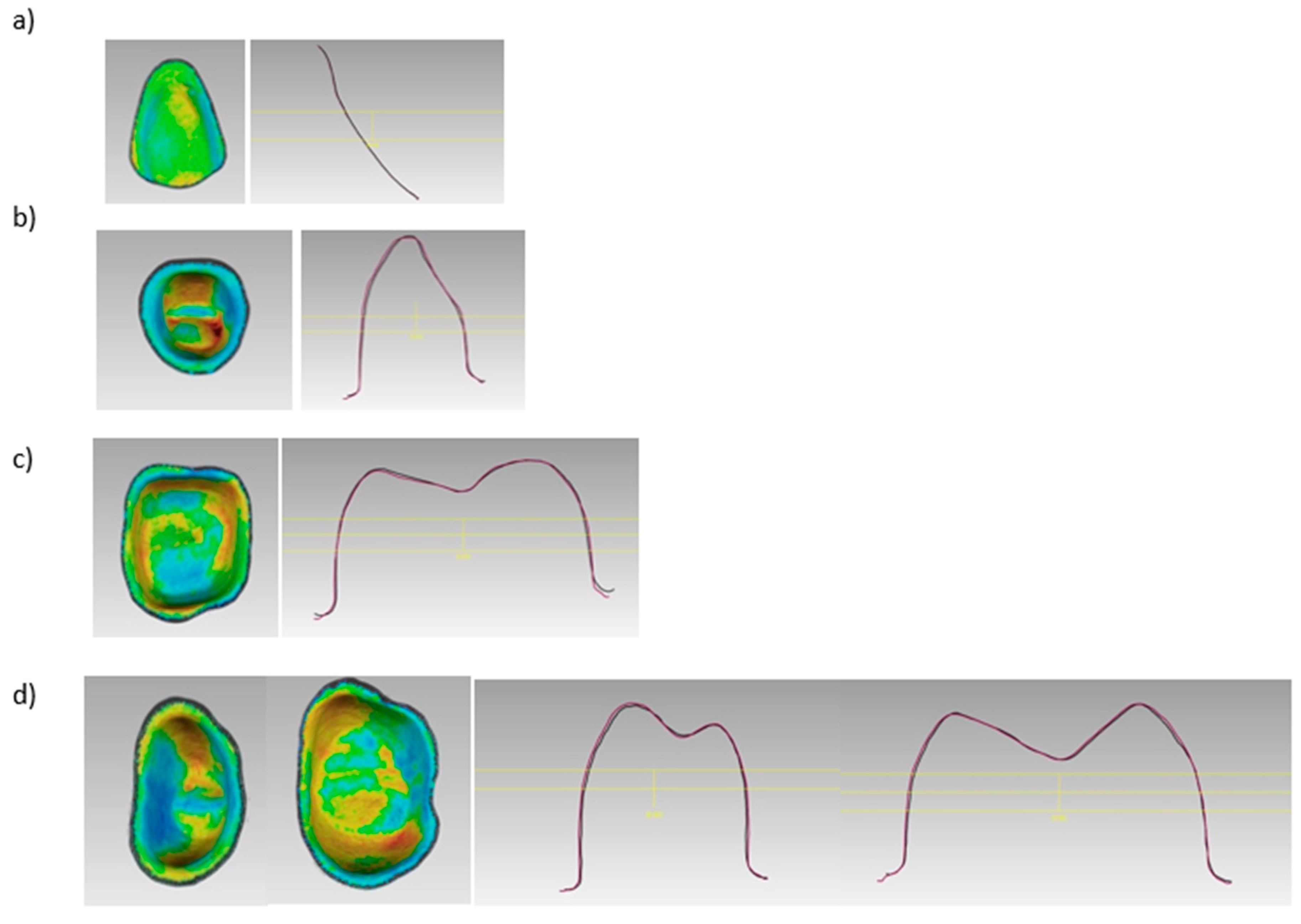
Figure 18.
A cross section of the superimposed CAD copings (purple lines) and the 3D-printed copings (black lines) demonstrated for the casted FPDs; a) veneer, b) incisor, c) molar, and d) four-unit FPD.
Figure 18.
A cross section of the superimposed CAD copings (purple lines) and the 3D-printed copings (black lines) demonstrated for the casted FPDs; a) veneer, b) incisor, c) molar, and d) four-unit FPD.
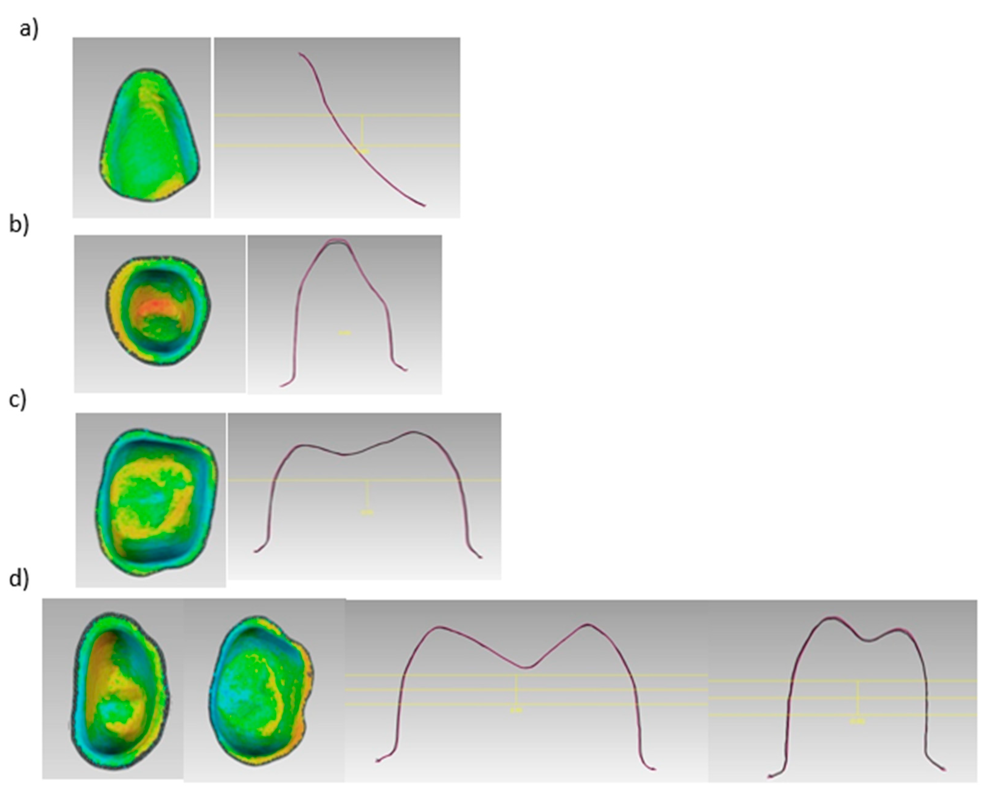
Figure 19.
A cross section of the superimposed CAD copings (purple lines) and the 3D-printed FDPs (black lines) demonstrated for the provisional FPDs; a) veneer, b) incisor, c) molar, and d) four-unit FPD.
Figure 19.
A cross section of the superimposed CAD copings (purple lines) and the 3D-printed FDPs (black lines) demonstrated for the provisional FPDs; a) veneer, b) incisor, c) molar, and d) four-unit FPD.
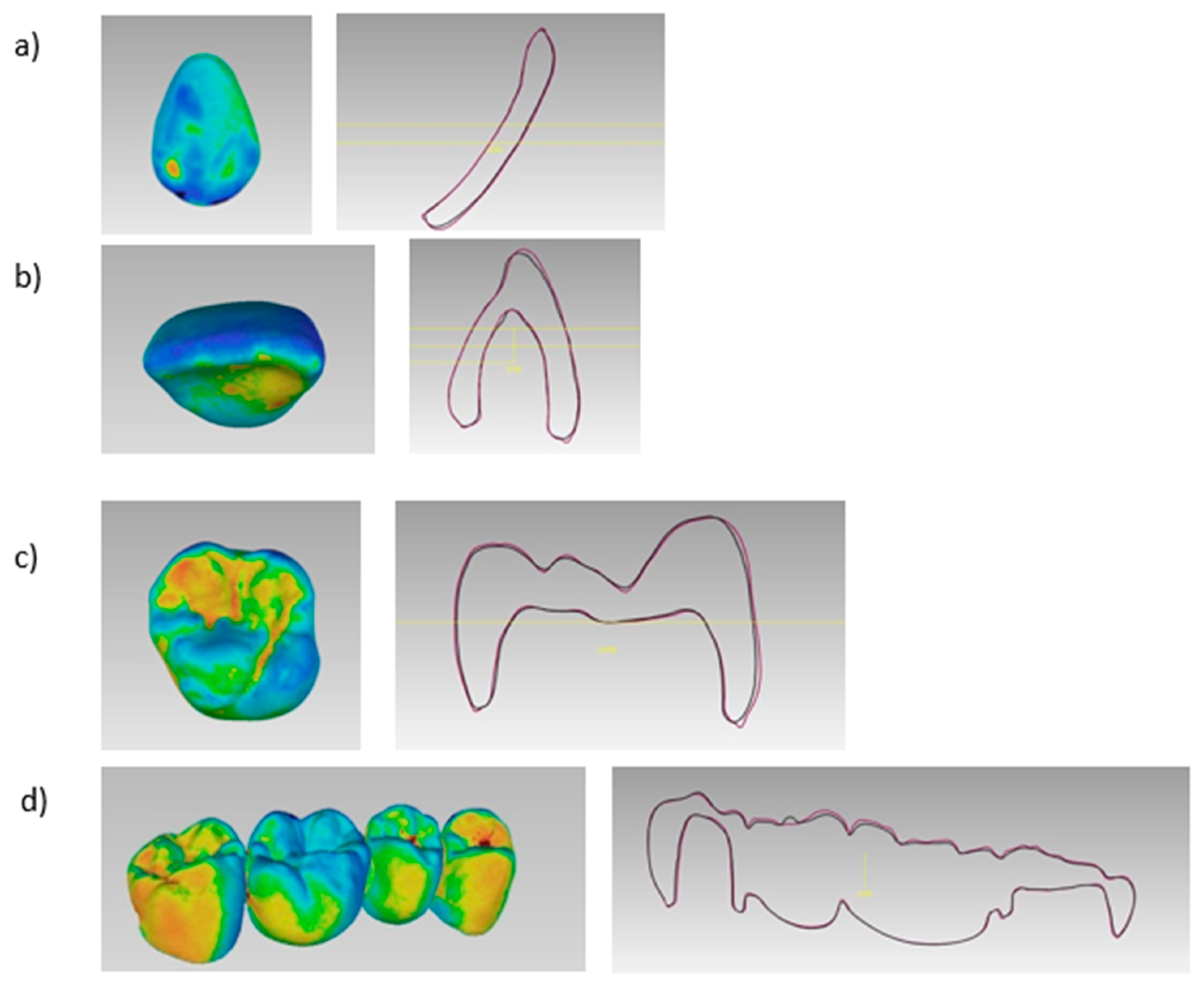
Figure 20.
A cross section of the superimposed CAD copings (purple lines) and the 3D-printed FDPs (black lines) demonstrated for the casted FPDs; a) veneer, b) incisor, c) molar, and d) four-unit FPD.
Figure 20.
A cross section of the superimposed CAD copings (purple lines) and the 3D-printed FDPs (black lines) demonstrated for the casted FPDs; a) veneer, b) incisor, c) molar, and d) four-unit FPD.
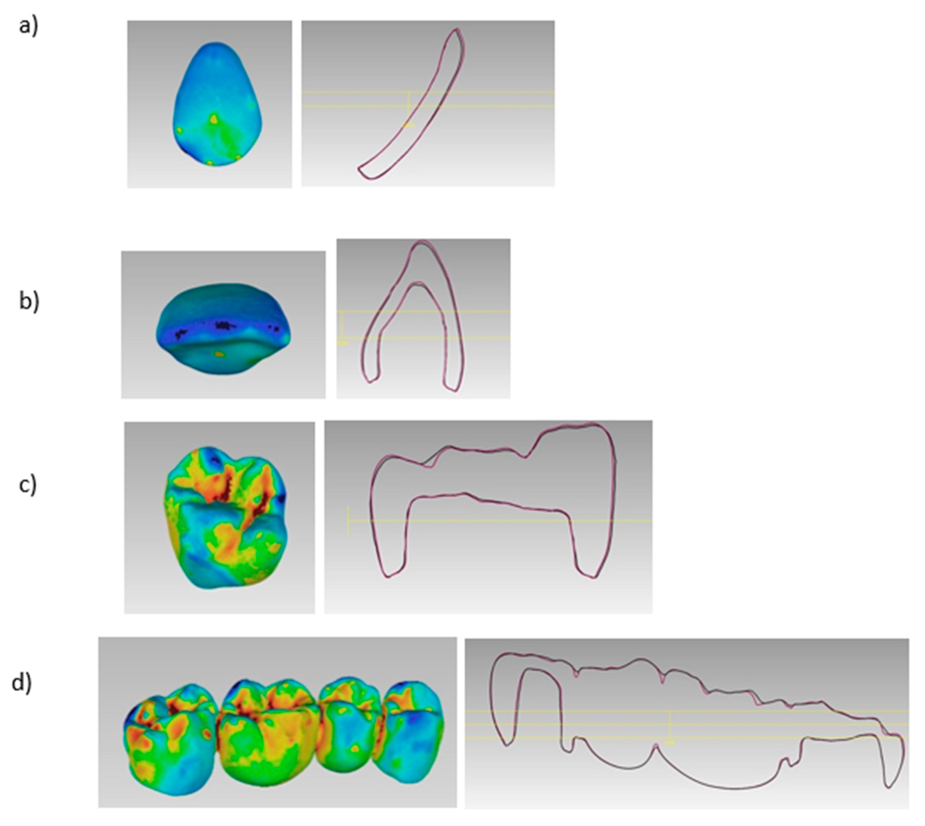

Table 1.
Summary of the main applications and materials of 3D-printing in dentistry [1,2,3,4,5,6,7,8,9,10]. SLA= Stereolithography; DLP= Direct Light Processing; CLIP= Continuous Liquid Interface; LCD= Liquid Crystal Display; SLS= Selective Laser Sintering; FDM= Fused Deposition Molding; EBM= Electron Beam Melting; ABS= Poly(acrylonitrile/butadiene/styrene); PEEK= Polyether Ether Ketone; PEKK= Polyetherketoneketone; Co/Cr= Chrome Cobalt, *= Experimental Phase.
| Material | 3D-printing Technology | Dental Applications |
|---|---|---|
|
Polymer-based: - Castable Resins - Hard Polymer - Clear Hard Polymers - Resin Composite Tooth Shade - Resin Composite Gingiva Elastic Shade - Waxes - Polyethylene - Polylactic Acid - Polycarbonate - Polysulfide - Polycaprolactone - ABS - PEEK* - PEKK* |
Vat-polymerization SLA Vat-polymerization DLP Vat-polymerization CLIP Vat-polymerization LCD Material Jetting Powder-based Fusion SLS Material Extrusion FDM |
Casts, casted metal frameworks, pressed lithium disilicate wax restorations, surgical diagnosis, surgical guides, occlusal devices, deprogrammers, silicone indices, custom trays, interim restorations, denture teeth, mock-up restorations, denture bases, bone analogs, orthodontic aligners. |
|
Metal-based - Co-Cr Alloys - Titanium - Gold |
Powder-based Fusion SLS Powder-based Fusion SLM Powder-based Fusion EBM |
Surgical guides, splinting frameworks for complete arch impression techniques, frameworks for removable partial dentures, frameworks for tooth- and implant-supported prostheses, crowns, dental implants, and maxillofacial prosthetic parts. |
|
Ceramic-based - Zirconia* - Lithium Disilicate* - Hybrid Ceramics* |
Vat-polymerization SLA Vat-polymerization DLP Material Jetting Material Extrusion FDM Powder-based Fusion SLS |
Tooth-supported Restorations |
Table 2.
Overall trueness values of the 3D-printed restorations.
| Trueness | |||
| Volumetric Changes | P-Value |
Formlabs (Castable) |
Shera (Provisional) |
| Veneers | 0.854 | 88 ± 26 µm | 85 ± 41 µm |
| Incisors Labial | 0.001 | -97 ± 84 µm | -77 ± 98 µm |
| Incisors Palatal | 22 ± 83 µm | 64 ± 91 µm | |
| Molars | 0.002 | 53 ± 19 µm | 77 ± 42 µm |
| FPDs | 0.004 | 181 ± 91 µm | 214 ± 89 µm |
| Copings | p-Value |
Formlabs (castable) |
Shera (provisional) |
| Veneers | 0.909 | 18 ±7 µm | 17 ± 2 µm |
| Incisors | 0.012 | 31 ± 4 µm | 52 ± 20 µm |
| Molars | 0.001 | 23 ± 2 µm | 31 ± 4 µm |
| FPDs # 14 |
0.001 |
47 ± 9 µm | 52 ± 6 µm |
| FPDs # 17 | 25 ± 2 µm | 44 ± 6 µm | |
Table 3.
Overall precision values of the 3D-printed restorations. * LCL= Lower control limit; UCL: Upper control limit.
Table 3.
Overall precision values of the 3D-printed restorations. * LCL= Lower control limit; UCL: Upper control limit.
| Precision | |||
| External dimensional changes | p-Value |
Formlabs (LCL–UCL)* (castable) |
Shera (LCL-UCL)* (provisional) |
| Veneers | 0.054 | -3- 179 µm | -26- 198 µm |
| Incisors labial |
0.892 |
59- 139 µm | 69- 160 µm |
| Incisors palatal | 59- 137 µm | 64- 149 µm | |
| Molars | ≦ 0.001 | 2- 103 µm | -32- 188 µm |
| FPDs | 0.101 | 169 – 270 µm | 206 – 328 µm |
| Internal dimensional changes | p-Value |
Formlabs (LCL–UCL)* (castable) |
Shera (LCL-UCL)* (provisional) |
| Veneers | 0.002 | 0.5 – 36 µm | 7 – 28 µm |
| Incisors | ≦ 0.001 | 2 – 4 µm | 1 – 11 µm |
| Molars | 0.305 | 1 -5 µm | 2- 8 µm |
| FDPs # 14 |
0.012 |
6 – 12 µm | 3 – 13 µm |
| FDPs # 17 | 1 – 6 µm | 4 – 14 µm | |
Disclaimer/Publisher’s Note: The statements, opinions and data contained in all publications are solely those of the individual author(s) and contributor(s) and not of MDPI and/or the editor(s). MDPI and/or the editor(s) disclaim responsibility for any injury to people or property resulting from any ideas, methods, instructions or products referred to in the content. |
© 2024 by the authors. Licensee MDPI, Basel, Switzerland. This article is an open access article distributed under the terms and conditions of the Creative Commons Attribution (CC BY) license (http://creativecommons.org/licenses/by/4.0/).
Copyright: This open access article is published under a Creative Commons CC BY 4.0 license, which permit the free download, distribution, and reuse, provided that the author and preprint are cited in any reuse.


