Submitted:
20 February 2024
Posted:
21 February 2024
Read the latest preprint version here
Abstract
The article delves into the crucial realm of compressing hydrogen in its gaseous state, a pivotal process for enhancing its viability in both civil and industrial sectors. The study initiates by providing a concise overview and comparison of diverse hydrogen storage methodologies, laying the groundwork with an in-depth analysis of hydrogen's thermophysical properties. It scrutinizes plausible configurations for hydrogen compression, aiming to strike a delicate balance between energy consumption, predominantly derived from the fuel itself, and the requisite number of compression stages. Notably, to render hydrogen storage competitive in terms of volume, pressures of at least 350 bar are deemed essential, albeit at an energy cost amounting to approximately 10% of the fuel's calorific value. Multi-stage compression emerges as a crucial strategy, not solely for energy efficiency, but also to curtail temperature rise, with an upper limit set at 200°C. This nuanced approach is underlined by the exploration of compression levels commonly cited in the literature, particularly 350 bar and 700 bar. Ultimately, the study advocates for a three-stage compression system as a pragmatic compromise, capable of achieving high-pressure solutions while keeping compression work below 10 MJ/kg, a threshold indicative of sustainable energy utilization.
Keywords:
Hydrogen storage
; Gaseous Compression
; Multi-Stage Configuration
; Energy analysis
; Efficiency
1. Introduction
Hydrogen, as widely acknowledged, serves as a crucial energy carrier, and its role in the energy transition is intricately tied to the ability to store energy harnessed from renewable sources. There is significant emphasis on hydrogen and its relevance. However, the prevailing perception is that the debate tends to be overly general, initially encompassing broad elements while potentially overlooking some crucial technical aspects (Ajanovic et al. 2024, [1]). The discussion about hydrogen has been ongoing for over 40 years, yet the lack of compelling solutions for widespread applications is still tied to certain technical aspects related to materials and intrinsic challenges of hydrogen. Additionally, it’s important to clarify that hydrogen is a carrier and as such needs to be integrated into an energy chain where energy balances must be respected, and the overall process efficiency must be acceptably high. The recent interest in hydrogen is primarily associated with its potential integration with the increasing penetration of renewable energy in energy systems. As outlined in Figure 1, illustrating how hydrogen can be integrated into a complex energy system, hydrogen can effectively complement the energy chain, providing an additional opportunity to further incorporate renewable sources, especially intermittent ones like wind and PV solar. Figure 1 illustrates a potential integration of hydrogen, highlighting the significance of energy storage as well. It is imperative, therefore, to maintain a comprehensive understanding of all components within the entire value chain.
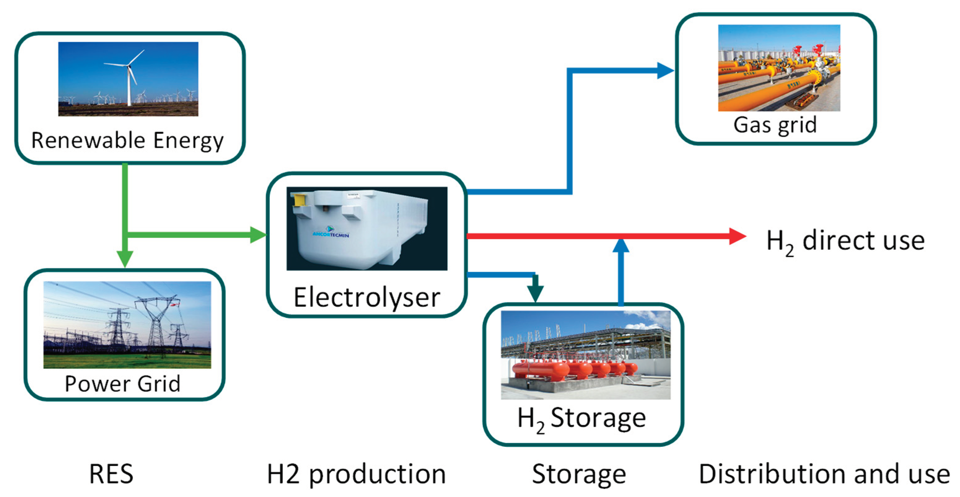
Figure 1.
Potential role of hydrogen storage in the energy chain.
Essentially, the significance of hydrogen lies in its potential to facilitate load leveling in systems anticipating an escalating integration of intermittent or non-programmable renewable sources. Hence, it becomes imperative to address hydrogen storage in a comprehensive manner. Despite hydrogen’s high specific energy per unit mass, 120 MJ/kg as Lower Heating Value (LHV), its low energy density per unit volume (about 10 MJ/m3) presents a challenge for achieving compact, cost-effective, and secure energy-dense storage solutions. The subject of hydrogen storage has been under scrutiny for an extended period, leading to the proposition of various storage methods at different junctures. However, determining an outright superiority among these methods remains elusive. Various storage methods exist, each with its own advantages and drawbacks, considering both cost and performance factors that depend on specific application requirements, Makridis, 2017, [2].
Currently, there isn’t a universally ideal storage technology for most applications. These methods generally fall into two categories: physical storage, where elemental hydrogen is stored, and materials-based storage, where hydrogen is bound within other materials. Under a different perspective Hydrogen can be stored through three fundamental methods: Compressed Hydrogen Gas (CGH2), Liquid Hydrogen (LH2), and Solid Storage of Hydrogen (SSH2). The latter, involving modification of hydrogen’s physical state, encompasses categories such as physisorption in porous materials, absorption on interstitial sites in a host metal, complex compounds, and metals and complexes with water. (Bossel et Eliasson in [3]).
Some recent papers cover a spectrum of hydrogen storage technologies, providing insights into their status, advancements, and the potential implications for a sustainable energy future. Arsad et al. (2022), in [4] explores the integration of hydrogen energy storage within hybrid renewable energy systems. The review provides a comprehensive analysis of current research trends and discusses future directions for this field. Wieliczko and Stetson in [5], emphasizes the importance of hydrogen as an energy carrier and discusses various technologies in this context. Usman et al. in [6], presents a thorough review of hydrogen storage methods and their status. The paper delves into the strengths and limitations of different storage approaches, shedding light on the advancements in this critical area.
Hassan et al. in [7] contributes to the discourse on the hydrogen energy future by focusing on advancements in storage technologies and their implications for sustainability. Muthukumar, et al. in [8] review the worldwide developmental status of large-scale hydrogen storage demonstrations using various storage technologies such as compressed, cryogenic, liquid organic hydrogen carrier, and solid-state hydrogen storage.
In the literature analysis it is possible to find also mention to electrochemical compression of hydrogen. This is a promising method that utilizes electrochemical reactions to compress hydrogen gas. This process typically involves the use of proton exchange membrane (PEM) cells. A theoretical advantage of electrochemical compression is its ability to achieve high compression ratios with relatively low energy consumption compared to mechanical compression methods even if research in this area is ongoing. Despite electrochemical hydrogen compression being a seemingly promising field in theory, it is currently very challenging to consider it as a technology that could be available within a reasonable timeframe.
Considering the more “conventional” methods, from the literature analysis, the conclusion drawn is that while each avenue can be considered, they all come with their own potentials and limitations, suggesting adaptability to specific contexts.
Liquid storage of hydrogen is first highly energy-intensive due to the energy requirements associated with the liquefaction process. The process of converting gaseous hydrogen into liquid hydrogen involves cooling the gas to extremely low temperatures, typically below -240 °C (in general – 253 °C). Moreover, storing hydrogen in a liquid phase demands the maintenance of extremely low temperatures (hydrogen transitions to a liquid state at 20 K under atmospheric pressure).
The storage of hydrogen in liquid form demands considerable energy and technologically advanced transportation infrastructure, making it suitable for transporting large quantities of hydrogen over long distances but less feasible for smaller-scale solutions. The storage and transportation of liquid hydrogen demand specialized and well-insulated containers to maintain the low temperatures required. This adds to the complexity and cost of the infrastructure needed for the compression and storage of hydrogen in liquid form. The complexity of the infrastructure is not offset by a significant increase in hydrogen density, considering that at 1 bar and -253 °C it is on the order of 70 kg/m3.
When considering liquefied natural gas as a comparison, operating at a temperature of -162°C, methane density is approximately 420 kg/m3, around 6 times higher than that of hydrogen. Consequently, from an energy standpoint, for an equal volume of the vessel, less than half the energy is transported, resulting in a ratio of approximately 5/2.
This energy requirement makes the overall hydrogen compression process less energy-efficient, as well outlined in the paper by Zhang et al., [9].
The challenges and energy costs associated with its compression, liquefaction, and storage make alternative compression methods, such as gaseous compression or solid-state storage, more attractive in certain applications.
Hydrogen storage through metal hydrides, holds conceptual promise but introduces additional challenges related to material stability, rendering its practical use complex. Numerous studies delve into the intricacies of hydrogen storage, examining both general and specific forms. Hydrogen storage in metal hydrides, involves chemically binding hydrogen to certain metals to form hydrides has some advantages, but it also comes with certain challenges and problems.
The selection of an appropriate metal hydride is critical. Different metals have different thermodynamic properties, kinetics, and stability characteristics. Finding a suitable metal hydride that meets the storage requirements for a particular application can be a complex task. Anyway, additional problems connected to kinetics of hydrogen, temperature, and pressure conditions (metal hydrides require specific temperature and pressure conditions to absorb and release hydrogen efficiently and this can lead to the need for additional heating or cooling mechanisms, adding complexity to the storage system), cycling stability and material degradation.
Recent developments and the anticipated widespread utilization of hydrogen suggest that, for various reasons, gaseous compression remains the most promising, especially for medium and small-scale applications [2]. Various technologies are employed for hydrogen compression, each with its own advantages and limitations. Some common hydrogen compression technologies include piston compressors, diaphragm compressors, used for small and small to medium scale application and screw compressors, that use rotating screws to compress hydrogen, as evidenced by Sdanghi et al. in [10].
Performance in hydrogen compression is evaluated based on factors such as energy efficiency, compression ratio, and safety. Achieving high compression ratios is crucial for storage and transportation applications. However, it’s essential to balance this with energy efficiency to minimize energy consumption. Research and development efforts continue to improve the efficiency and economics of hydrogen compression technologies. Innovations aim to address challenges such as heat management during compression to enhance overall performance. However, it’s crucial to note that even with the widespread adoption of gaseous compression, the limited density of hydrogen at ambient conditions requires pushing towards high pressures, typically exceeding 300 bar. The application of higher pressures brings thermodynamic advantages. An exploration of hydrogen’s thermophysical properties reveals that, at environmental temperature and 500 bar pressure, the hydrogen density is around 30 kg/m3—approximately 300 times higher than ambient conditions. The density further increases to about 50 kg/m3 under compression at 1000 bar. Nevertheless, the use of very high pressures introduces a myriad of challenges, necessitating the use of specialized materials with significant structural strength, resistance to embrittlement, and incurring a more substantial energy expenditure to meet specific requirements. This energy expenditure adds to a host of other factors, often rendering the hydrogen energy chain inefficient.
In addition to energy costs associated with the electrolysis phase, the substantial energy consumption during the compression process and end-use poses a risk of substantial reductions in overall process efficiencies. Despite the extensive history of dealing with hydrogen and hydrogen compression, identifying literature addressing the establishment of reasonable compression pressure targets that strike a balance between various elements (compression work, storage system dimensions, physical characteristics, and associated costs) proves challenging. Hence, this work, following an in-depth analysis of the current state of gaseous hydrogen accumulation techniques, aims to outline criteria utilizing a multi-objective optimization approach, seeking to define optimized accumulation systems tailored to specific applications.
In the literature, the topic of compressing hydrogen in gaseous form has been extensively explored (Zheng et al., [11]). However, the rationale behind the prevalent choices of two pressure levels (350 bar or 700 bar) remains unclear, and a criterion for defining an optimal compromise among various process parameters is lacking.
The study aims to systematically analyze the issue of compressing hydrogen in gaseous form, seeking to establish criteria and guidelines for identifying technological solutions that offer prospects for medium-term pursuit. It considers both material-related challenges (such as maximum temperature limits) and feasible technological solutions (compression ratios and number of stages) relevant to industrial and civilian contexts. Moreover, through various sensitivity analyses, the study seeks to evaluate the energy requirements and the technological objectives to pursue, all while avoiding an excessive push towards technological innovation. This research is motivated by the growing importance of hydrogen as a clean and sustainable energy carrier. In the subsequent sections, we will discuss the methodology employed for modeling hydrogen compression and the analysis of commercial compressors. Through our investigation, we aim to provide valuable insights into the thermodynamic performance of hydrogen compression systems and identify opportunities for improving their efficiency and sustainability. The paper is organized as follows. Section 3 discuss the key thermophysical properties of hydrogen relevant to compression and outline the storage requirements for gaseous hydrogen; Section 3 gives a short review existing technological solutions for compressing gaseous hydrogen, examining their advantages and limitations. Section 4 presents a compression model for analyzing energy requirements, including a sensitivity analysis to explore variations in parameters, while Section 5 discuss the results of the compression analysis, comparing the actual compression work required for different combinations of initial and final pressure. Conclusions summarize the findings from the study, highlighting key insights and implications for hydrogen compression technology, and suggest areas for future research.
2. Thermophysical properties of hydrogen and gas compression storage requirements
Hydrogen stands out as an element renowned for its thoroughly documented thermophysical properties. Its allure lies in its energy potential, boasting a notably high lower calorific value of 120 MJ/kg; this promising energy carrier encounters a limitation in the form of its diminished density, particularly under atmospheric pressure conditions.
From the analysis of hydrogen’s thermophysical properties, it is evident that gas-phase compression is thermodynamically advantageous. Liquid-phase compression, on the other hand, requires at least the same amount of work, but since the fraction of liquid separated is smaller, as depicted in the figure for a generic Linde compression cycle, a significant portion of the calorific power would be subtracted from the process. This is shown in a schematic way in Figure 2.

Table 1.
Energy content of hydrogen and other fuels at environmental temperature and pressure.
| Fuel | Energy per liter [MJ/l] |
|---|---|
| Hydrogen (ambient pressure) | 0,0107 |
| Natural gas (ambient pressure) | 0,0364 |
| Methane (ambient pressure) | 0,0378 |
Thinking about a generic gas like hydrogen, in the T-p diagram, during Joule-Thomson transformations, there is a zone where the derivative of temperature with respect to pressure, while keeping enthalpy constant (a quantity called the Joule-Thomson coefficient μ), is positive. It represents the rate of change of temperature with respect to pressure for a fluid undergoing throttling or expansion without external work or heat transfer.

This fact allows for the possibility of liquefying a gas through a simple expansion or, better, throttling. Indeed, if the coefficient μ is negative, then decreasing the pressure increases the temperature, whereas if μ is positive, decreasing the pressure in the expansion or throttling of Joule-Thomson also decreases the gas temperature, enabling its liquefaction. However, it should be noted that in the case of hydrogen, as well highlighted in the right portion Figure 1, the zone of saturated vapors is well below the inversion zone, so it is necessary to both compress and cool the fluid to be liquefied. In the right part of Figure 2 is represented a liquefaction process based on the Joule-Thomson effect. As well evidenced in Figure, this not only involves significant energy expenditure but also results in the separation of a relatively small portion of hydrogen in liquid form, making it clear how compression in the liquid phase is unlikely to be a convenient solution, mainly from an energy point of view. In general, as shown in Figure 3, whether one wants to store hydrogen in liquid form or in gaseous form, it will be necessary to significantly increase the gas pressure, which will allow for a significant increase in density.
The thermophysical properties of hydrogen are so disadvantageous that even high-pressure gas compression and liquefaction bring them closer to conventional fuels, albeit still at a certain distance. As can be observed from an analysis of Figure 2, the energy content of hydrogen expressed in MJ/l, even with a compression level of 700 bar, is still about 1/7 of that available with the main liquid fuels typically used in the energy sector. Even liquefaction, despite all the highlighted issues, does not solve the problem. The issue of compressing hydrogen in gaseous form encompasses various aspects, including the significant consideration of storage vessels. Historically, certain pressure levels, such as 350 bar and 700 bar, have been identified as structurally feasible, with four distinct types of containers available for storage. A paper from Barthelemy, [12], provides a historical and technical overview of hydrogen storage vessels and discusses the challenges and constraints of hydrogen energy applications. It explores the storage of hydrogen as a compressed or refrigerated liquefied gas, detailing the evolution of storage methods from seamless steel cylinders to aluminum cylinders and hoop-wrapped metallic cylinders. The development of fully wrapped composite tanks for high-pressure hydrogen storage is examined, along with the specific issues associated with these technologies. Additionally, the storage of hydrogen in liquid form is discussed, tracing the use of cryogenic vessels since the 1960s. The topic of compressed hydrogen structures is certainly of great importance and is inherently linked to the determination of storage pressures, but it is not elaborated on in this work.
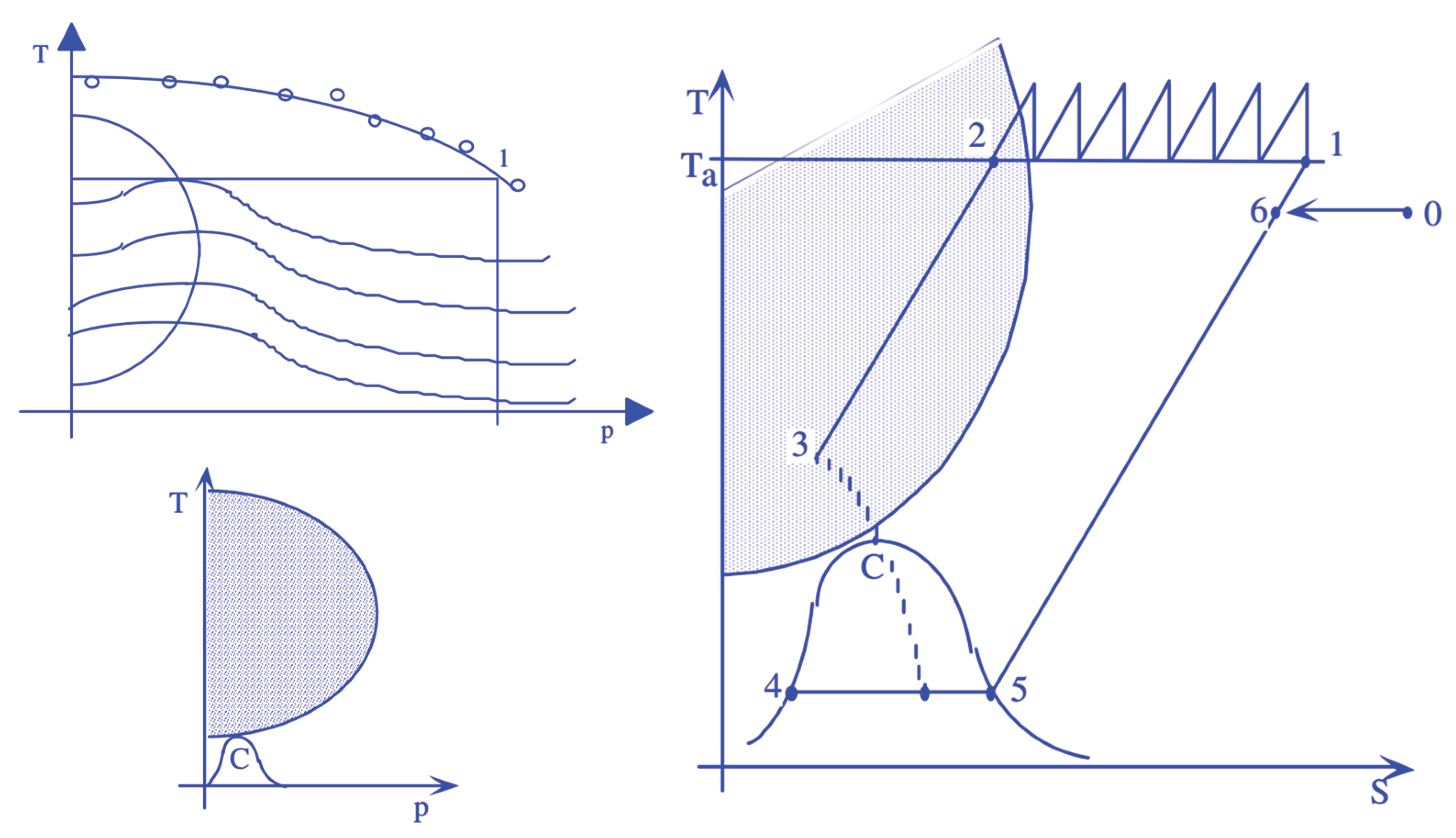
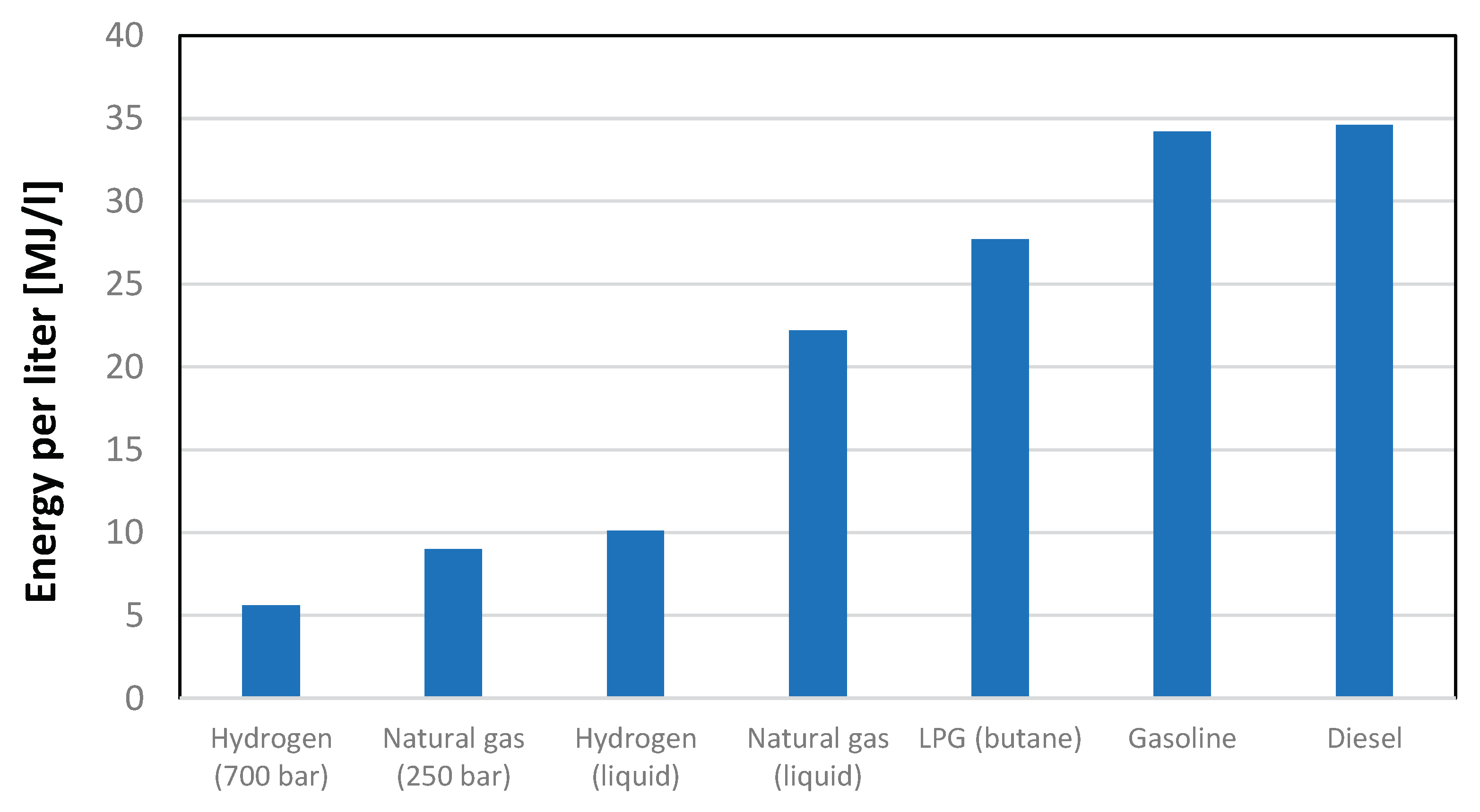
Figure 2.
Hydrogen compression as a gas or in liquid form.
Figure 3.
Volumetric energy content of different fuels in different operating conditions.
To compress the gas, multi-stage compression is typically employed. However, this compression transformation does not occur adiabatically because it would result in very high energy consumption. For this reason, compression is carried out in multiple stages, and between each stage, the hydrogen must be adequately cooled.
To better understand the issues associated with hydrogen compression, whether aimed at maintaining it in liquid or gaseous conditions, it is necessary to have a clear idea of the orders of magnitude associated with the two phases. The thermophysical properties of hydrogen can be quantitatively visualized in the graph depicted in Figure 4, rearranged, and readapted from Grestein and Klell, in [13] and Klell, [14], representing the temperature range from 0 K up to a temperature of 325 K. To understand the pressure that need to be reached, next table elucidates various density values achievable through the judicious manipulation of pressure and temperature variables. A discernible pattern emerges, showcasing a substantial upswing in density with the application of higher pressure and the simultaneous reduction in temperature. This correlation underscores the dynamic interplay between these thermodynamic factors, providing valuable insights for optimizing hydrogen storage and utilization strategies. Table 2 presents various density values achievable by NIST webbook database, [15] strategically combining pressure and temperature.
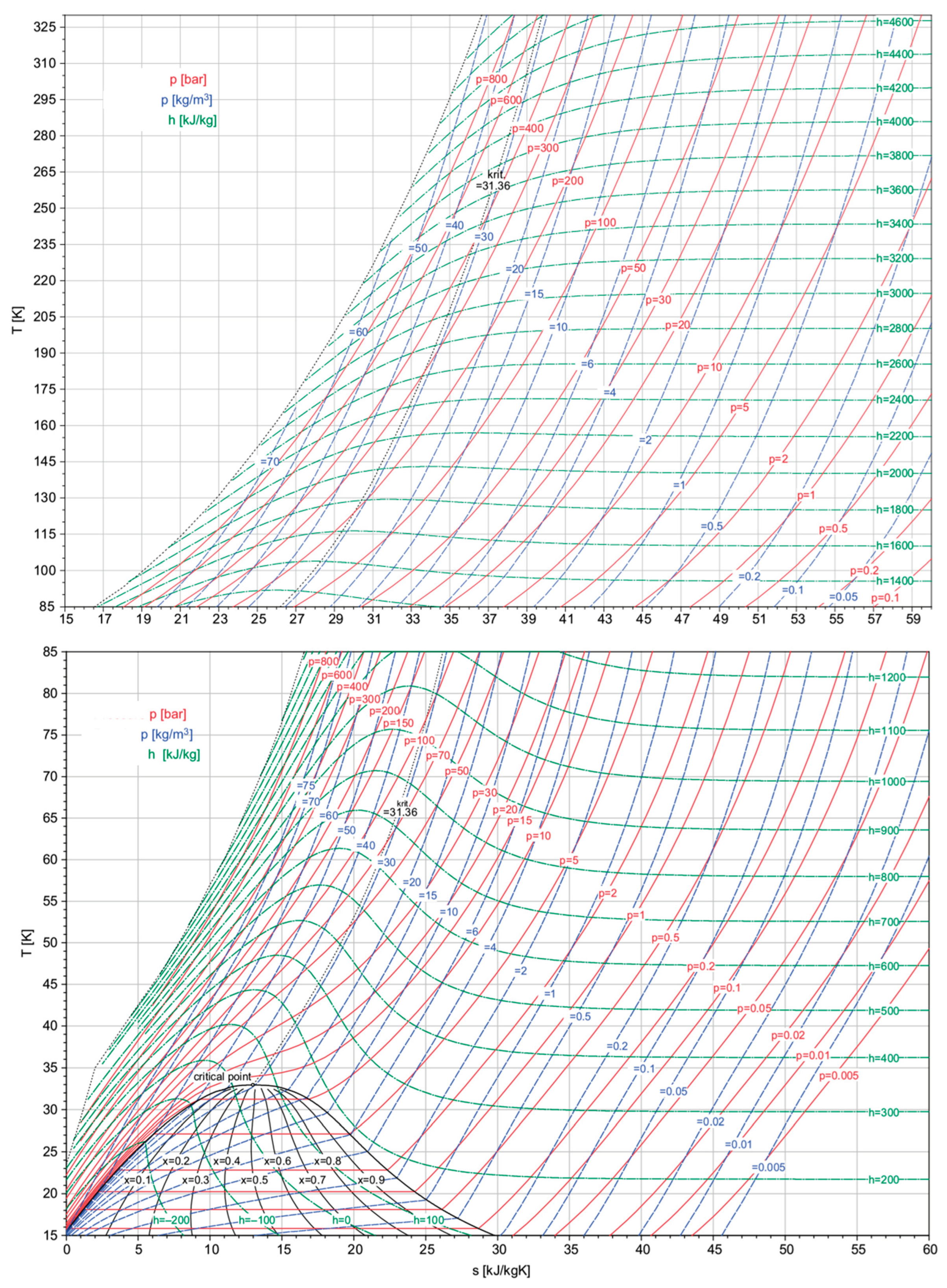
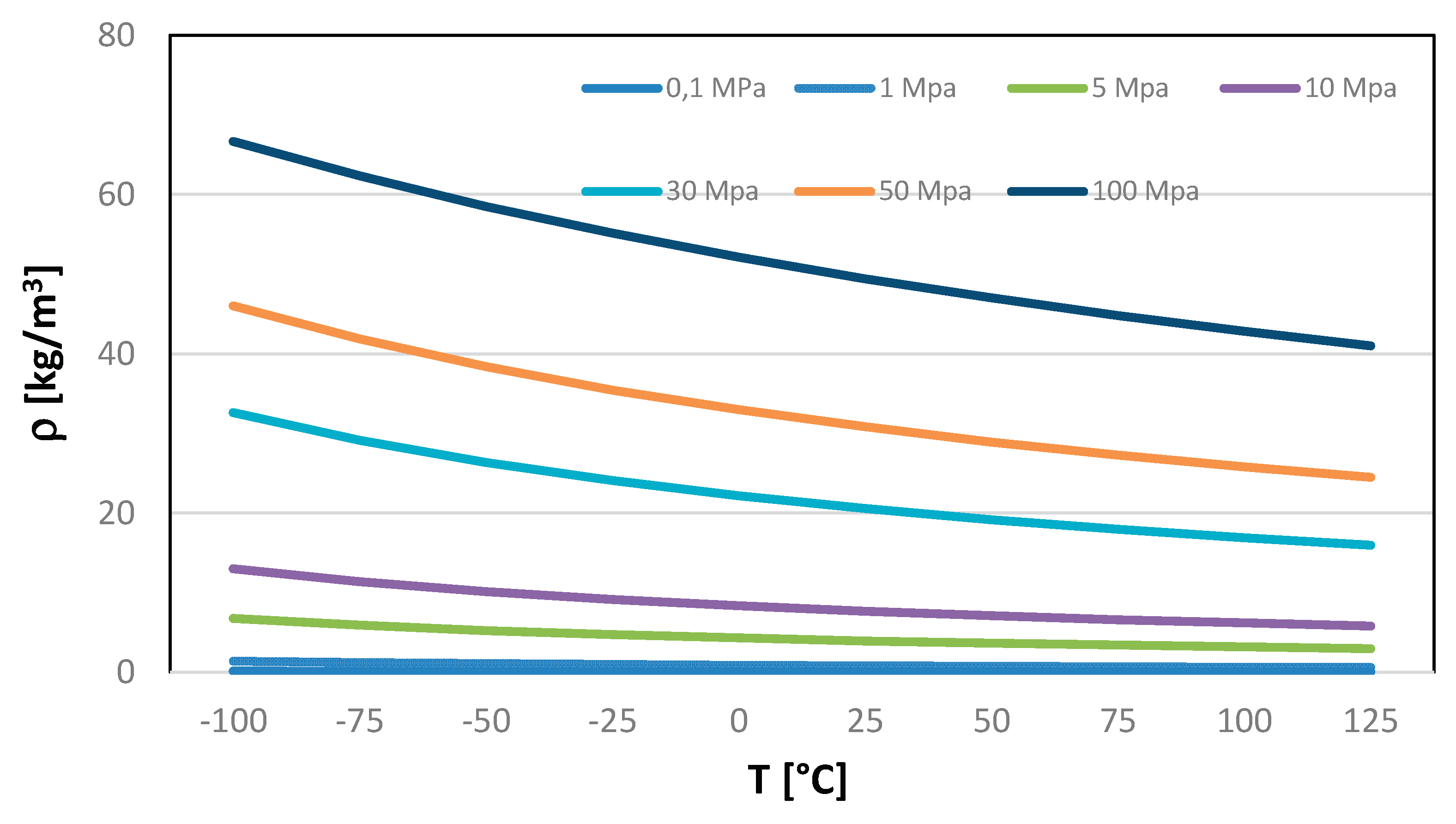
Figure 4.
Hydrogen thermophysical properties in a T-s diagram. (Readapted and Rearranged from the original reported by Grestein and Klell, [13] and Klell, [14]).
Table 2.
Hydrogen density (kg/m3) at Different Temperatures (°C) and Pressures (MPa).
| T [°C] | 0,1 MPa | 1 Mpa | 5 Mpa | 10 Mpa | 30 Mpa | 50 Mpa | 100 Mpa |
|---|---|---|---|---|---|---|---|
| -100 | 0,1399 | 1,3911 | 6,7608 | 12,992 | 32,614 | 46,013 | 66,660 |
| -75 | 0,1223 | 1,2154 | 5,9085 | 11,382 | 29,124 | 41,848 | 62,322 |
| -50 | 0,1086 | 1,0793 | 5,2521 | 10,141 | 26,336 | 38,384 | 58,503 |
| -25 | 0,0976 | 0,9708 | 4,7297 | 9,1526 | 24,055 | 35,464 | 55,123 |
| 0 | 0,0887 | 0,8822 | 4,3036 | 8,3447 | 22,151 | 32,968 | 52,115 |
| 25 | 0,0813 | 0,8085 | 3,9490 | 7,6711 | 20,537 | 30,811 | 49,424 |
| 50 | 0,0750 | 0,7461 | 3,6490 | 7,1003 | 19,149 | 28,928 | 47,001 |
| 75 | 0,0696 | 0,6928 | 3,3918 | 6,6100 | 17,943 | 27,268 | 44,810 |
| 100 | 0,0649 | 0,6465 | 3,1688 | 6,1840 | 16,883 | 25,793 | 42,819 |
| 125 | 0,0609 | 0,6061 | 2,9736 | 5,8104 | 15,944 | 24,474 | 41,001 |
Figure 5.
Hydrogen density as a function of temperature and pressure.
Density experiences a significant increase with higher pressure and lower temperatures. The compressibility factor (Z) of a gas is a dimensionless quantity that reflects how much the gas deviates from ideal behavior. For an ideal gas, the compressibility factor is always equal to 1. However, real gases, including hydrogen, deviate from ideal behavior under certain conditions. In the case of hydrogen, the compressibility factor tends to increase with increasing pressure and decreasing temperature. The deviation from ideal gas behavior is more pronounced under conditions where the gas particles are closer together and experience stronger intermolecular forces, such as at high pressures or low temperatures. So, your observation aligns with the non-ideal behavior of hydrogen, and the increasing compressibility factor signifies that hydrogen exhibits deviations from ideal gas behavior, especially under conditions of elevated pressure and reduced. Compressed hydrogen storage encompasses a spectrum of pressure levels tailored for diverse applications. Small-scale storage, utilizing spherical vessels, commonly operates at 20 bars. Medium-scale storage in pipelines typically involves a pressure of 100 bar, while industrial-scale storage utilizes pressures in the range of 200–300 bar. Operational pressures for hydrogen fuel cells in light- and heavy-duty road transport span from 350 bar to 700 bar. Hydrogen refueling stations, servicing both light- and heavy-duty road transport, necessitate storage at 1000 bar.
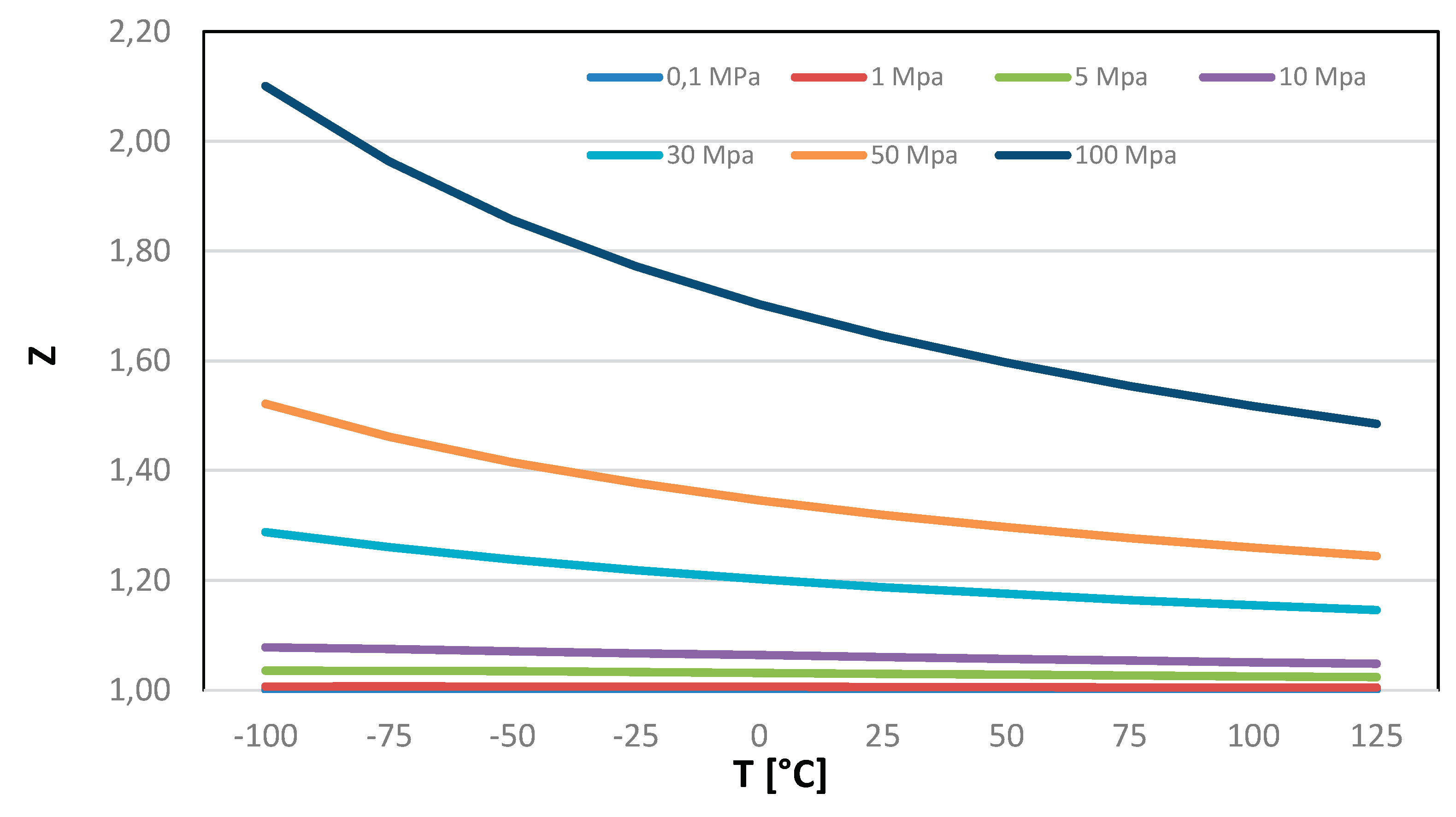
Table 3.
Compressibility factor Z of Hydrogen at Different Temperatures (°C) and Pressures (MPa).
| T [°C] | 0,1 MPa | 1 Mpa | 5 Mpa | 10 Mpa | 30 Mpa | 50 Mpa | 100 Mpa |
|---|---|---|---|---|---|---|---|
| -100 | 1.0007 | 1.0066 | 1.0356 | 1.0778 | 1.2880 | 1.5216 | 2.1006 |
| -75 | 1.0007 | 1.0068 | 1.0355 | 1.0751 | 1.2604 | 1.4620 | 1.9634 |
| -50 | 1.0007 | 1.0067 | 1.0344 | 1.0714 | 1.2377 | 1.4153 | 1.8572 |
| -25 | 1.0006 | 1.0065 | 1.0329 | 1.0675 | 1.2186 | 1.3776 | 1.7725 |
| 0 | 1.0006 | 1.0062 | 1.0313 | 1.0637 | 1.2022 | 1.3462 | 1.7032 |
| 25 | 1.0006 | 1.0059 | 1.0297 | 1.0601 | 1.1879 | 1.3197 | 1.6454 |
| 50 | 1.0006 | 1.0056 | 1.0281 | 1.0567 | 1.1755 | 1.2969 | 1.5964 |
| 75 | 1.0005 | 1.0053 | 1.0266 | 1.0536 | 1.1644 | 1.2770 | 1.5542 |
| 100 | 1.0005 | 1.0050 | 1.0252 | 1.0507 | 1.1546 | 1.2596 | 1.5175 |
| 125 | 1.0005 | 1.0048 | 1.0240 | 1.0481 | 1.1458 | 1.2441 | 1.4852 |
Figure 6.
Hydrogen Compressibility (Z) at Different Temperatures and Pressures.
Determining the optimal compression pressure for storing hydrogen in gaseous form is a nuanced challenge, requiring a compromise between energy considerations, aiming to minimize the impact on compression work, and economic and safety factors. The latter involves ensuring that containers do not incur an excessively high cost due to structural requirements and materials. Identifying an optimum point among these diverse objectives becomes crucial for each application, underscoring the need for a tailored approach. It is evident that pursuing a specific objective aligned with the unique characteristics of each application is imperative to address the complexities inherent in hydrogen storage.
3. Gaseous hydrogen compression: analysis of technological solutions available
Hydrogen compression in gaseous form plays a crucial role in various applications, including hydrogen storage, transportation, and energy conversion. Several compression methods are known:
- Mechanical Compression: this traditional method involves compressing hydrogen using mechanical devices such as piston compressors, diaphragm compressors, or screw compressors. While widely used in some practical applications, mechanical compression can be energy intensive.
- Electrochemical Compression: this emerging method utilizes electrochemical reactions to compress hydrogen. It involves electrochemically splitting water into hydrogen and oxygen, followed by compression of the hydrogen gas. Electrochemical compression shows promise for its potential energy efficiency and compatibility with renewable energy sources.
- Hydraulic Compression: it involves using hydraulic pumps to compress hydrogen. This method offers high efficiency and can be suitable for applications requiring high-pressure hydrogen storage.
- Sorption-based Compression: Sorption-based compression utilizes the adsorption or absorption of hydrogen onto solid materials to achieve compression. This method can be energy-efficient and is being explored for various storage and compression applications.
Recent advancements in hydrogen compression technology focus on improving efficiency, reducing energy consumption, and enhancing safety. Research efforts also aim to address challenges such as material compatibility, system reliability, and cost-effectiveness. Among the others, mechanical compression is a widely used method for compressing hydrogen gas to higher pressures. This process typically involves the use of mechanical devices such as piston compressors, diaphragm compressors, or screw compressors.
In a piston compressor, hydrogen gas is drawn into a cylinder and compressed by a piston moving in a reciprocating motion. Diaphragm compressors use flexible diaphragms to compress the gas, while screw compressors utilize rotating screws to decrease the volume of the gas. Hydrogen compression presents not only an energy challenge but also a material integrity concern. Hydrogen can induce embrittlement in metallic materials, reducing their ductility despite maintaining their strength. This can lead to the instability of defects that may be acceptable without hydrogen, posing potential fracture risks from a fracture mechanics or fit-for-service standpoint.
Small-scale storage using spherical vessels commonly operates at 2 MPa. Medium-scale storage in pipes typically involves a pressure of 10 MPa [16,17]. Industrial-scale storage utilizes pressures in the range of 20–30 MPa [18]. High operational pressures for light- and heavy-duty road transport span from 35 to 70 MPa [19]. Hydrogen storage in large production areas to hydrogen refuelling stations and/or industrial users may require compressing hydrogen up to 100 MPa. The isobaric and isenthalpic curves of interest for the storage of H2 in compressed gaseous form are qualitatively represented in Figure 7.
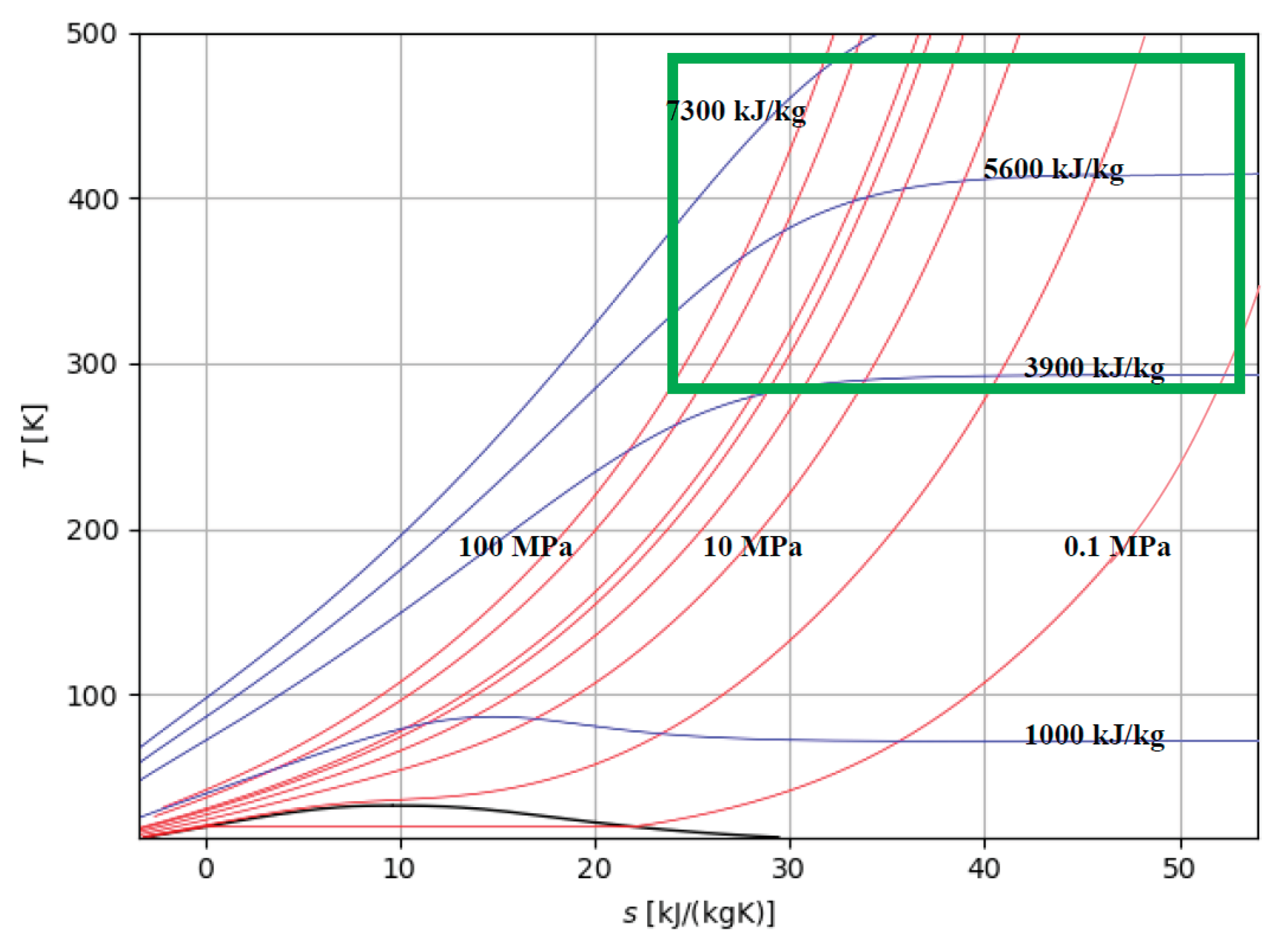
Figure 7.
Zone of interest for the storage of H2 in compressed gaseous form: isobaric (red lines) and isenthalpic (blue lines) curves and aree of interest (green).
Figure 7.
Zone of interest for the storage of H2 in compressed gaseous form: isobaric (red lines) and isenthalpic (blue lines) curves and aree of interest (green).
As can be seen from the data in Table 4, analyzing some compressors found in the literature reveals that the maximum pressure level reached is approximately 450 bar, with the most frequently used pressure being around 350 bar. Compressors typically have 3 or 4 stages; however, compressors with 5 stages are available too.
Considering the data provided in Table 4 and referencing a total compression ratio of 350, the specific work associated with compression varies from approximately 10 MJ/kg for larger-sized compressors to over 26 MJ/kg for smaller-sized compressors. The nominal power of the various available models ranges from 4 kW up to 230 kW and the number of stages is from 3 to 5. Compressor with maximum output pressure of 700 bar are not available in the market.
Table 4.
Specification of some compressor of the commercial type.
| Compressor type | Inlet pressure [bar] |
Outlet pressure [bar] | Pressure ratio | Volumetric Flow rate [m³/h] |
Nominal power [kW] |
Specific work compression [MJ/kg] |
|---|---|---|---|---|---|---|
| 3 stages | 24-30 | 350-450 | 14.6-15 | 7-13 | 4-5.5 | 18.35-24.78 |
| 4 stages | 1 | 350 | 350 | 26 | 15 | 25.02 |
| 4 stages | 1 | 350 | 350 | 36 | 22 | 26.50 |
| 4 stages | 1 | 350 | 350 | 76 | 38 | 21.68 |
| 5 stages | 1 – 20 | 350 | 17.5-350 | 1000 | 132 – 230 | 5.72-9.98 |
Data for converting flow meter in kg/h: 1 m3/h (20°C, 1,013 hPa) = 0,083 kg/h.
4. Compression model and energy requirements for hydrogen compression: sensitivity analysis
Compressing hydrogen into gaseous form is conceptually quite simple. As can be seen from the data in Table 1, it is necessary to reach a certain level of pressure. Compressing hydrogen from atmospheric pressure to a high pressure, such as 350-700 bar, demands a significant energy input. In this section, we explore the modeling of hydrogen compression, focusing on the comparison between idealized isothermal compression and real-world compression processes.
We begin by examining the theoretical framework of isothermal compression, where the compression process occurs at constant temperature. Under ideal conditions, isothermal compression requires a minimal amount of energy input, as dictated by the ideal gas law. However, real-world compression systems deviate from ideal behavior due to factors such as friction, heat transfer, and inefficiencies inherent in mechanical components.
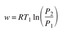
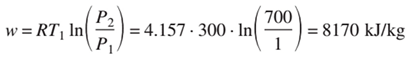
Through mathematical modeling and simulation, we investigate how these deviations impact the energy requirements of hydrogen compression. By comparing the energy expenditure of idealized isothermal compression with real-world compression processes, we aim to quantify the efficiency losses associated with practical compression systems. This analysis provides valuable insights into the thermodynamic limitations and performance characteristics of hydrogen compression technologies. Considering a thermodynamic perspective, the process of isothermal reversible compression requires the least amount of work, and this can be computed under the assumption of ideal gas behavior with the following equation. [Zangh et al., 2005].
So, considering the energy required to obtain a final pressure of 700 bar, starting from temperature of 300 K, it can be assumed to be about 8.17 MJ/kg, while it is about 7.30 MJ/kg for a compression between 1 and 350 bar.
Clearly, the evaluation provided by equation (2) only gives a rough estimation of the minimum energy required to achieve the desired pressure, as it does not account for the non-ideal behavior of the gas, as highlighted in Figure 4. This non-ideal behavior becomes more pronounced as the final pressure increases. However, Table 4 still provides, for illustrative purposes, the densities associated with the achieved pressure level and the minimum specific work obtainable by applying equation (2).
From a technical point of view, two pressure levels are generally known at which compressions are made: 350 bar, in the case of small and medium-sized applications and 700 bar in the case of larger-sized applications. Obviously, none of these pressures can be obtained with a single compression step since, from a technological point of view, it is difficult to think of going beyond a compression ratio of 7. Therefore, starting from the level of atmospheric pressure, to arrive at a level of 350 bar at least 3 stages are necessary. To reach 700 bars, at least 4 compression levels are required. However, since the compressions are irreversible adiabatic and cause an increase in temperature, it is necessary to remain below a certain temperature level (200 °C).
In practical scenarios, the temperature of hydrogen undergoes a considerable increase even when utilizing advanced multi-stage intercooling technology during compression. As a result, it is more accurate to characterize the compression process as a polytropic compression. The energy consumption for this type of process can be roughly determined by the following equation, using a polytropic exponent, that accordingly with the most diffused textbooks of Thermodynamics can be assumed to be n=1.36.
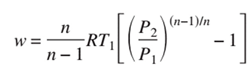
Table 5.
Specific work for ideal isothermal compression and polytropic compression (with n=1,36) of hydrogen from 300 K and 0.1 MPa to a final pressure.
Table 5.
Specific work for ideal isothermal compression and polytropic compression (with n=1,36) of hydrogen from 300 K and 0.1 MPa to a final pressure.
| Final H2 pressure [MPa] |
Density [kgH2/m3] |
wiT,id [MJ/kgH2] |
wpol |
|---|---|---|---|
| 2 | 1.6 | 3.73 | 4.28 |
| 10 | 7.8 | 5.74 | 13.05 |
| 20 | 14.7 | 6.61 | 20.55 |
| 30 | 20.8 | 7.11 | 26.70 |
| 35 | 23.8 | 7.30 | 29.48 |
| 70 | 40 | 8.17 | 51.71 |
| 100 | 50 | 8.61 | 57.52 |
As evidenced by the data analysis presented in Table 5, the findings indicate a significant overestimation of compression work, particularly noticeable when targeting higher pressures. This underscores the necessity for a multi-stage compression approach with intercooling, rather than a simple polytropic compression with index n, which would result in excessively high specific work requirements and compression temperatures well above ambient levels.
If one approaches the evaluation of the compression process as if it were isothermal, two crucial elements are overlooked. On one hand, there might be a temptation to substantially increase the compression pressure, leading to a significant rise in hydrogen density. On the other hand, the full understanding of the energy expenditure associated with the storage process would not be fully grasped. Due to the limitation of a pressure ratio of approximately 7 for each stage, achieving a pressure level of 350 bar necessitates three compression stages, while reaching 700 bars would require at least four stages. So, considering Equation (3), assuming perfect intercooling, where the gas is cooled to the initial temperature before each subsequent stage, literature estimates indicate that the minimum compression work can quickly escalate to 10.2 kJ/kg (calculated using a polytropic index n=1.36, assumed considering the contemporary action of refrigeration system). This value is still 25% higher than that needed for an ideal isothermal process. However, an additional complication arises due to the presence of a compressibility factor.
The practical energy consumption for hydrogen compression in real application, typically exceeds the theoretical minimum by at least 2.5 times. Consequently, in the case of reaching 700 bars, it can be higher than 20 MJ/kg, marking an unsustainable level, especially when considering it constitutes more than 15% of calorific value. A more accurate assessment can be made by considering the differences in enthalpy at various compression stages, considering plausible values for isentropic efficiency.
Figure 8 shows the temperature-entropy diagram of an intercooled multi-stage compression with four stages of compression, where p1 is the initial pressure of hydrogen to store and p8 equals the storage pressure desired (pst). The work of compression per kg of hydrogen in an intercooled multi-stage process (wm-s) can be evaluated by the sum of the enthalpy changes between the stages. In an intercooled multi-stage compression, the specific work (wm-s) can be evaluated, as schematically referred in Figure 5 by the isentropic efficiency (ηis) of the compressor, where referring to four compression stages:
and in general
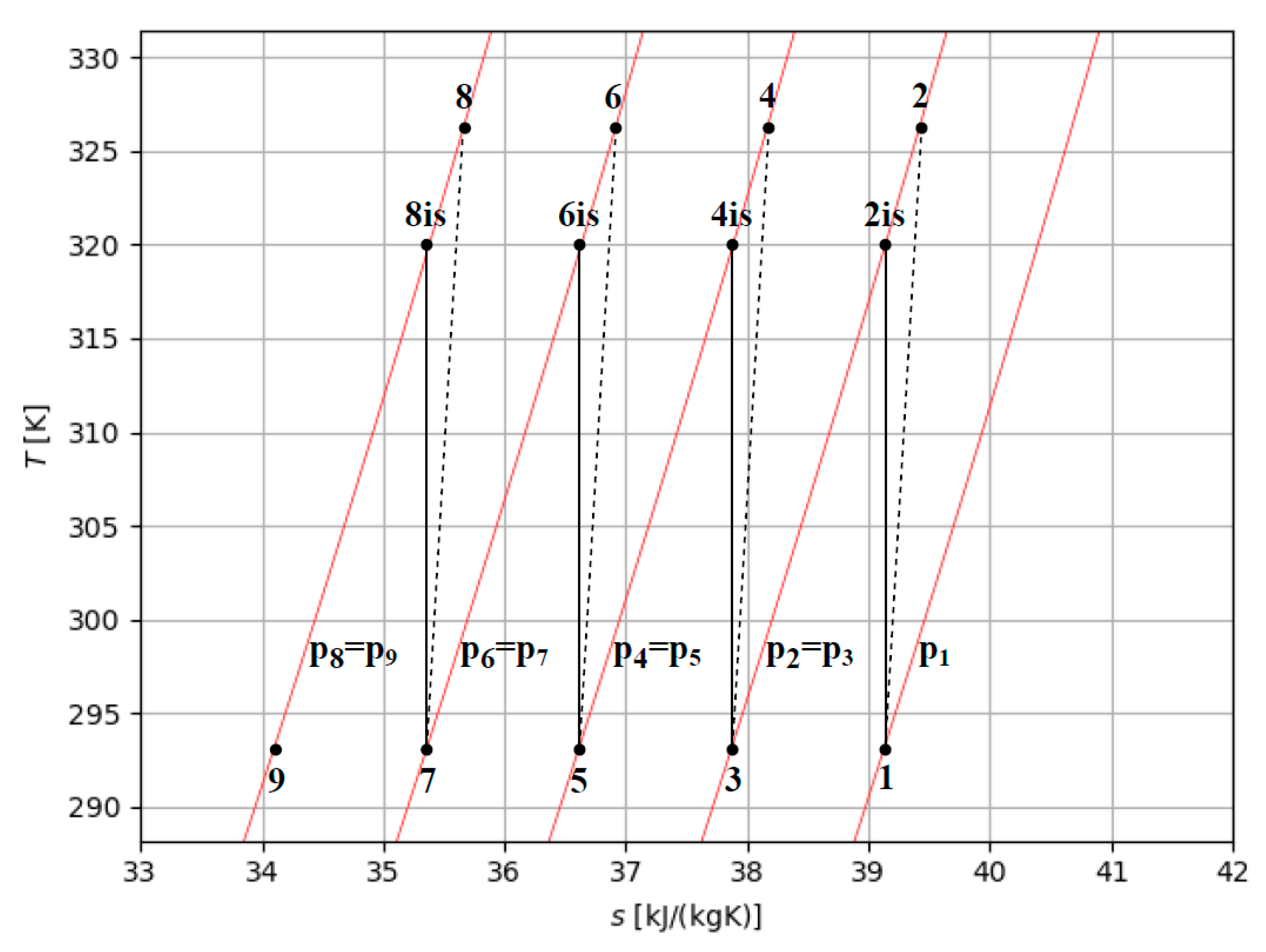
Figure 7.
Temperature-entropy diagram of an intercooled four stages compression.
The corresponding power of compressor can be estimated considering the hydrogen mass flow rate as:
In general, to estimate the compression work, it is necessary to define the intermediate pressures of compression (pint), i.e. the pressures at which the gas is intercooled between one stage and the following one. Thus, for example, pint,1 equals the final pressure of the first stage and the initial pressure of the second stage of compression.
As the storage pressure (pst) varies, conventional intermediate pressures could be used, but this could lead to higher end-of-compression temperatures and greater specific compression work. Reflecting on the ideality of isothermal compression which would require infinite compression stages, the intermediate pressures can be chosen using next equation:
when the initial compression work (p1) equals 1 bar or a different value. This choice can minimize the maximum temperature reached in compression and the specific work (wm-s) necessary as the storage pressure and the number of stages vary, causing the intercooled multi-stage compression to tend towards the ideal isothermal compression.
To reach a well-defined pressure, the compression work is minimum when all compressions have the same compression ratio (β), so that:
In the context of hydrogen gas compression processes, it’s important to consider that if hydrogen is introduced at environmental pressure (1 bar) the maximum compression ratio cannot exceed 7. This means that to achieve a pressure level of 350 bar, at least 3 compression stages are required (1-7, 7-49, 49-343 bar). However, another significant factor to consider is the maximum temperature during compression, which should ideally not exceed 150-200 °C to avoid hydrogen embrittlement issues. Consequently, the maximum compression ratio between stages should not exceed 5. Therefore, in practical technical solutions, reaching a pressure level of 350 bar is commonly associated with the use of at least 4 compression stages, theoretically allowing for pressure levels of approximately 700 bar (1-5, 5-25, 25-125, 125-725 bar). Within the realm of hydrogen production, focusing specifically on low-temperature water electrolysis, hydrogen can be generated within a pressure range of 1 to 30 bar, resulting in a multitude of potential combinations.
5. Analysis of the real compression work with respect to the various combination of initial and final pressure
Considering an isentropic compression efficiency of 0.8, along with the initial pressure of the hydrogen and the desired pressure at the end of the process, as well as the maximum temperature achievable due to structural constraints, it follows the need to determine the optimal number of compression stages. As observed in Table 6, in terms of the specific work required for gas compression, the difference between using 2, 3, or 4 compression stages is not particularly significant. However, what is noteworthy is the maximum temperature: while with two stages it reaches approximately 217 °C, 3 or 4 stages allow for much greater limitation of the maximum temperature. Similar considerations can be made in the case where the goal is to achieve a final gas pressure of 10 MPa; in this scenario, it is obviously not feasible to work with only two compression stages since the compression ratio would be approximately 10 (Table 7). The situation becomes more complicated if aiming to achieve a final pressure of 350 bar. In this case, maintaining reasonable value of maximum temperature requires 4 or 5 compression stages. The compression work required is on the order of 11 MJ/kg, a value that is approximately 10% of the fuel’s calorific value. Table 8 shows the data related to the two cases with 4 or 5 compression stages. Obviously, the specific energy required for compression increases as the isentropic compression efficiency decreases. Table 9 illustrates the scenario where the isentropic compression efficiency is reduced to 0.7. If the isentropic efficiency (ηis) decreases, the maximum temperature, and the specific work of compression increase.
Table 6.
Specific work for multi-stage compression to 2 MPa (ηis=0.80): Tin = 20 °C, pin = 0.1 MPa.
| Number of stages | T2 [°C] |
p2 [MPa] |
T4 [°C] |
p4 [MPa] |
T6 [°C] |
p6 [MPa] |
T8 [°C] |
wm-s [MJ/kgH2] |
|---|---|---|---|---|---|---|---|---|
| 2 | 216.7 | 0.5 | 214.8 | 5.67 | ||||
| 3 | 140.5 | 0.3 | 142.6 | 0.7 | 140.8 | 5.26 | ||
| 4 | 106.8 | 0.2 | 109.5 | 0.5 | 107.6 | 1.0 | 107.3 | 5.07 |
Table 7.
Specific work for multi-stage compression to 10 MPa (ηis=0.80): Tin = 20 °C, pin = 0.1 MPa.
Table 7.
Specific work for multi-stage compression to 10 MPa (ηis=0.80): Tin = 20 °C, pin = 0.1 MPa.
| Number of stages | T2 [°C] |
p2 [MPa] |
T4 [°C] |
p4 [MPa] |
T6 [°C] |
p6 [MPa] |
T8 [°C] |
wm-s [MJ/kgH2] |
|---|---|---|---|---|---|---|---|---|
| 3 | 220.2 | 0.5 | 222.9 | 2.2 | 222.8 | 8.84 | ||
| 4 | 164.6 | 0.3 | 162.7 | 1.0 | 162.5 | 3.2 | 162.8 | 8.34 |
Table 8.
Data for intercooled multi-stage compression (ηis=0.80) from 0.1 MPa and 20 °C to 35 MPa.
| Number of stages | T2 [°C] |
p2 [MPa] |
T4 [°C] |
p4 [MPa] |
T6 [°C] |
p6 [MPa] |
T8 [°C] |
p8 [MPa] |
T10 [°C] |
wm-s [MJ/kgH2] |
|---|---|---|---|---|---|---|---|---|---|---|
| 4 | 209.5 | 0.4 | 211.4 | 1.9 | 211.4 | 8.1 | 212.5 | 11.34 | ||
| 5 | 164.6 | 0.3 | 167.0 | 1.0 | 166.7 | 3.4 | 166.7 | 10.9 | 167.6 | 10.86 |
Table 9.
Optimized specific work of compression from 20 °C and 0.1 MPa. Multistage intercooled compression with ηis=0.70, varying the storage pressure and the number of stages.
Table 9.
Optimized specific work of compression from 20 °C and 0.1 MPa. Multistage intercooled compression with ηis=0.70, varying the storage pressure and the number of stages.
| pst [MPa] |
Three stages | Four stages | Five stages | |||
|---|---|---|---|---|---|---|
| Tmax [°C] |
wm-s [MJ/kg] |
Tmax [°C] |
wm-s [MJ/kg] |
Tmax [°C] |
wm-s [MJ/kg] |
|
| 2 | 160 | 6.0 | 122 | 5.8 | 100 | 5.7 |
| 10 | 185 | 9.5 | 147 | 9.2 | ||
| 20 | 214 | 11.4 | 171 | 10.9 | ||
| 30 | 232 | 12.5 | 185 | 12.0 | ||
| 35 | 242 | 13.0 | 191 | 12.4 | ||
| 70 | 219 | 14.5 | ||||
| 100 | 235 | 15.8 | ||||
As shown in Table 9, decreasing the isentropic efficiency from 0.8 to 0.7 results in both an increase in the specific work required for compression and a rise in the maximum temperature.
The use of initial compression pressure higher than 1 bar can be helpful to reduce the specific compression work and the maximum temperatures. Considering for example inlet pressure of 30 bar (available for hydrogen after electrolysis process), it is possible to reduce in a relevant way both the specific work of compression and the maximum temperature. Table 10 shows for example the date relative to 5 different values of the final pressures particularly, pst = 350, 700 or 1000 bar, typical values for high size storage infrastructures, like hydrogen re-fueling stations.
Referring the sensitivity analysis previously developed, we have established that the compression of hydrogen necessitates of an additional energy input, particularly noteworthy when dealing with substantial pressures increase, amounting to approximately 10% of the calorific value of hydrogen if a pressure ratio of 700:1 is considered.
This factor gains even more significance when considering that a portion of the energy has already been dissipated during the electrolysis process. It’s crucial to emphasize, however, that the energy expenditure during the compression phase does not escalate significantly in relation to the compression ratio. This implies that the selection of an optimal compromise between enhancing density and minimizing work input might be contingent on other critical factors. These factors include the maximum number of compression stages, the upper limit on compression temperature, and the maximum compression ratio associated with a single stage. Balancing these elements becomes pivotal in determining the overall efficiency and feasibility of hydrogen compression processes.
Table 10.
Intercooled multi-stage compression (ηis=0.80) with five stages from initial condition of 20 °C and 3 MPa.
Table 10.
Intercooled multi-stage compression (ηis=0.80) with five stages from initial condition of 20 °C and 3 MPa.
| pH2 [MPa] |
T2 [°C] |
p2 [MPa] |
T4 [°C] |
p4 [MPa] |
T6 [°C] |
p6 [MPa] |
T8 [°C] |
p8 [MPa] |
T10 [°C] |
wm-s [MJ/kgH2] |
|---|---|---|---|---|---|---|---|---|---|---|
| 35 | 75.9 | 4.9 | 75.9 | 8.0 | 76.0 | 13.1 | 76.2 | 21.4 | 76.6 | 4.29 |
| 70 | 92.1 | 5.6 | 92.9 | 10.5 | 93.4 | 19.7 | 94.5 | 37.1 | 95.9 | 5.87 |
| 100 | 100.9 | 6.0 | 102.3 | 12.1 | 102.8 | 24.4 | 103.7 | 49.2 | 106.8 | 6.82 |
As relevant concluding remarks of the analysis we can summarize the following main elements. Compression of hydrogen in the gaseous form requires relevant energy input, and for significant pressures, this energy input is approximately 10% of the calorific value of hydrogen. This is particularly notable, especially considering that a portion of the energy is already dissipated for hydrogen production, as for example in the electrolysis process.
It is important to highlight that the energy spent during the compression phase does not increase proportionally with the compression ratio. This suggests that the choice of an optimal compromise between increasing density and minimizing work input depends on various factors beyond the compression ratio itself.
The selection of an optimal compromise hinges on other relevant elements such as the maximum number of compression stages also involves considerations of the maximum compression temperature and the maximum compression ratio associated with a single stage.
Balancing all those elements becomes pivotal in determining the overall efficiency and feasibility of hydrogen compression processes. This underscores the need for a nuanced approach that considers multiple factors in achieving an effective and sustainable compression strategy for hydrogen.
Finally, we have seen how reaching a maximum pressure level of 700 bar is quite reasonable: lower pressure levels do not seem particularly advantageous, considering that the energy extracted from the process is not significantly higher than that required to achieve a pressure level of 350 bar. Of course, we must also consider that the energy expended for compression is energy withdrawn from the energy chain. Indeed, thinking about a system like the one depicted in Figure 1, hydrogen storage can be justified only by the need to introduce greater flexibility into the energy system and gaseous storage appears to be the most relevant. However, in terms of energy balance, of the 120 MJ contained in one unit of hydrogen mass, at least 40 MJ are dissipated in the electrolysis process (Franco and Giovannini, in [20]) and 10-15 MJ are additionally consumed in the compression phase. This means that more than 40-45% of the renewable energy converted is lost in the chain before utilization. The quantity would certainly be higher when considering storage in liquid form. Therefore, optimizing techniques for storing hydrogen in gaseous form is certainly an important objective, but it is still important to keep in mind that the use of storage must always be carefully evaluated.
6. Conclusions
This study examined the issue of hydrogen compression in gaseous form from a thermodynamic perspective. After outlining the context and analyzing some of the commercially available technical solutions, several cases of practical technical interest were evaluated. The specific work for compression depends on the desired final pressure and the maximum achievable temperature. Limiting the temperature to 150-200°C requires restricting the compression ratio between successive stages. Employing multiple compression stages is necessary to achieve high final pressures: for instance, to attain a pressure of 350 bar, at least 4 compression stages are required. The specific compression work is on the order of 11 MJ/kg, approximately 10% of the lower heating value of the fuel. This should be considered in assessing the overall energy efficiency. However, the achievable increase in density is significant, which may offset the energy cost of compression. Significant reductions in specific work can be achieved by using higher hydrogen inlet pressures, such as 30 bar. In this scenario, besides obtaining a substantial reduction in compression work, it’s possible to limit the temperature to slightly above 100°C. For example, using 5 compression stages, it is feasible to compress up to 1000 bar with an energy expenditure of approximately 6 MJ/kg, equivalent to around 5% of the fuel’s lower heating value. Here’s a concise summary of the provided information.
Examining the compression work required for different pressure combinations highlights the importance of optimizing compression stages. Data in Tables 6 and 7 underscore that while the number of compression stages affects temperature control, the specific work required remains relatively consistent. Achieving a pressure of 700 bar appears reasonable, considering marginal energy gains for lower pressures. However, it’s vital to recognize that energy expended during compression detracts from overall energy efficiency.
Approximately 40% of renewable energy is lost in the chain before utilization, with compression contributing significantly to this loss. The energy expended during compression doesn’t increase proportionally with the compression ratio, necessitating a nuanced approach to balancing efficiency and feasibility. The choice of compression strategy must consider factors like the number of compression stages, maximum compression temperature, and compression ratio. Achieving an optimal compromise between increasing density and minimizing work input is crucial for efficient hydrogen compression.
In summary, while optimizing compression techniques is crucial for hydrogen storage, careful evaluation of storage utilization remains essential, considering its impact on overall energy efficiency.
Author Contributions
Conceptualization, A.F.; formal analysis, A.F. and C.G.; methodology, A.F. and C.G.; data curation, A.F. and C.G.; supervision, A.F.; writing—original draft preparation, A.F., writing, review, and editing, A.F. and C.G. funding acquisition, A.F., All authors have read and agreed to the published version of the manuscript.
Funding
This work was supported by the National Recovery and Resilience Plan (NRRP), Mission 4 Component 2 Investment 1.3—Call for tender No. 1561 of 11.10.2022 of Ministero dell’Università e della Ricerca (MUR); project funded by the European Union—NextGenerationEU. Award Number: Project code PE0000021, Concession Decree No. 1561 of 11.10.2022 adopted by Ministero dell’Università e della Ricerca (MUR), CUP I53C22001450006, according to attachment E of Decree No. 1561/2022, Project title “Network 4 Energy Sustainable Transition—NEST”.
Acknowledgments
The data presented in this study are available upon request from the corresponding author
Conflicts of Interest
The authors declare no conflicts of interest.
Nomenclature
| h | specific enthalpy, kJ/kg |
| i | Generic i-th stage |
| LHV | lower heating value, MJ/kg |
| m | Hydrogen mass flow rate, kg/s |
| n | Exponent of polytropic transformation |
| ns | Number of compression stages |
| P, p | pressure, Pa (bar, MPa) |
| S | specific entropy, kJ/ (kg K) |
| R | Gas constant, J/kg K |
| T | temperature, K or °C |
| V | Compressor volumetric flow rate, m3/h |
| v | specific volume, m3/kg |
| W | Compressor power, kW |
| Z | Compressibility factor |
| w | specific work of compression, MJ/kg |
| b | Pressure ratio |
| r | density, kg/m3 |
| h | Efficiency |
| m | Joule Thomson coefficient, K/Pa |
Subscripts, superscripts, acronyms and abbreviations
| CGH2 | Compressed hydrogen gas |
| Id | Ideal |
| (g) | gaseous state |
| in | Inlet value |
| int | Intermediate |
| Is | Isentropic |
| IT | Isothermal |
| (l) | liquid state |
| LH2 | hydrogen in liquid form |
| Max | Maximum |
| m-s | intercooled multi-stage |
| pol | Polytropic |
| PV | PhotoVoltaic |
| SSH2 | Solid storage of hydrogen |
| st | Storage |
| WE | water electrolysis |
References
- Ajanovic, A., Sayer, M., & Haas, R. On the future relevance of green hydrogen in Europe. Applied Energy. 2024, 358, 122586. [CrossRef]
- Makridis, S. Hydrogen storage and compression. arXiv 2017. arXiv:1702.06015.
- Bossel U, Eliasson B, Energy and the hydrogen economy, US DOE, EERE, http://www.afdc.energy.gov/pdfs/hyd_economy_bossel_eliasson.pdf.
- Arsad, A. Z., Hannan, M. A., Al-Shetwi, A. Q., Mansur, M., Muttaqi, K. M., Dong, Z. Y., & Blaabjerg, F. Hydrogen energy storage integrated hybrid renewable energy systems: A review analysis for future research directions. International Journal of Hydrogen Energy, 2022, 47(39), 17285-17312. [CrossRef]
- Wieliczko, M., & Stetson, N. Hydrogen technologies for energy storage: A perspective. MRS Energy and Sustainability. 2020, 7, E41. [CrossRef]
- Usman, M. R. Hydrogen storage methods: Review and status. Renewable and Sustainable Energy Reviews 2022, 167, 112743. [Google Scholar] [CrossRef]
- Hassan, Q., Sameen, A. Z., Salman, H. M., Jaszczur, M., & Al-Jiboory, A. K. Hydrogen energy future: Advancements in storage technologies and implications for sustainability. Journal of Energy Storage, 2023 72, 108404. [CrossRef]
- Muthukumar, P., Kumar, A., Afzal, M., Bhogilla, S., Sharma, P., Parida, A., ... & Jain, I. P. Review on large-scale hydrogen storage systems for better sustainability. International Journal of Hydrogen Energy. 2023. [CrossRef]
- Zhang, J., Fisher, T. S., Ramachandran, P. V., Gore, J. P., & Mudawar, I. A review of heat transfer issues in hydrogen storage technologies. Journal of Heat Transfer DECEMBER. 2005, 127, 1391. [CrossRef]
- Sdanghi, G., Maranzana, G., Celzard, A., & Fierro, V. Review of the current technologies and performances of hydrogen compression for stationary and automotive applications. Renewable and Sustainable Energy Reviews. 2019, 102, 150–170. [CrossRef]
- Zheng, J., Liu, X., Xu, P., Liu, P., Zhao, Y., & Yang, J. Development of high-pressure gaseous hydrogen storage technologies. International journal of hydrogen energy, 2012, 37(1), 1048-1057. [CrossRef]
- Barthélémy, H. Hydrogen storage–Industrial prospectives. International journal of hydrogen energy, 2012, 37(22), 17364-17372. [CrossRef]
- Gstrein G, Klell M. Properties of hydrogen. Institute for Internal Combustion Engines and Thermodynamics, Graz University of Technology. 2004.
- Klell, M. Storage of hydrogen in the pure form. Handbook of hydrogen storage, 2010, 1-37.
- NIST. Thermophysical Properties of Fluid Systems. Available online at: https://webbook.nist.gov/chemistry/fluid/ (last access: January 2024).
- Witkowski, A., Rusin, A., Majkut, M., & Stolecka, K. Comprehensive analysis of hydrogen compression and pipeline transportation from thermodynamics and safety aspects. 2017. [CrossRef]
- Tahan, M. R. Recent advances in hydrogen compressors for use in large-scale renewable energy integration. International Journal of Hydrogen Energy, 2022, 47(83), 35275–35292. [CrossRef]
- Barthélémy, H., Weber, M., & Barbier, F. Hydrogen storage: Recent improvements and industrial perspectives. International Journal of Hydrogen Energy, 2017 42(11), 7254–7262. [CrossRef]
- Elberry, A. M., Thakur, J., Santasalo-Aarnio, A., & Larmi, M. Large-scale compressed hydrogen storage as part of renewable electricity storage systems. International journal of hydrogen energy, 2021, 46(29), 15671–15690. [CrossRef]
- Franco, A., & Giovannini, C. Recent and Future Advances in Water Electrolysis for Green Hydrogen Generation: Critical Analysis and Perspectives. Sustainability, 2023, 15(24), 16917. [CrossRef]
Disclaimer/Publisher’s Note: The statements, opinions and data contained in all publications are solely those of the individual author(s) and contributor(s) and not of MDPI and/or the editor(s). MDPI and/or the editor(s) disclaim responsibility for any injury to people or property resulting from any ideas, methods, instructions or products referred to in the content. |
© 2024 by the authors. Licensee MDPI, Basel, Switzerland. This article is an open access article distributed under the terms and conditions of the Creative Commons Attribution (CC BY) license (http://creativecommons.org/licenses/by/4.0/).
Copyright: This open access article is published under a Creative Commons CC BY 4.0 license, which permit the free download, distribution, and reuse, provided that the author and preprint are cited in any reuse.


