Submitted:
31 January 2024
Posted:
02 February 2024
You are already at the latest version
Abstract
The binary metal oxide mesoporous interfacial layers (bi-MO meso IF layer) templated by a graft copolymer is synthesized between a fluorine-doped tin oxide (FTO) substrate and nanocrystalline TiO2 (nc-TiO2). Amphiphilic graft copolymers, Poly(epichlorohydrin)-graft-poly(styrene), PECH-g-PS, was used as a structure-directing agent, and the fabricated bi-MO meso IF layer exhibits good interconnectivity and high porosity. Even if the amount of ZnO in bi-MO meso IF layer increased, it was confirmed that the morphology and porosity of bi-MO meso IF layer was well maintained. In addtion, bi-MO meso IF layer coated onto FTO substrates show higher transmittance compared with a pristine FTO substrate and dense-TiO2/FTO, due to the reduced surface roughness of FTO. The overall conversion efficiency (η) of a solid state photovoltaic cells, dye-sensitized solar cell (DSSC) fabricated with nc-TiO2 layer/bi-MO meso IF layer TZ1 used as a photoanode reaches 5.0% at 100 mW cm-2, which is higher than that of DSSC with a nc-TiO2 layer/dense-TiO2 layer (4.2%), resulting from enhanced light harvesting, good interconnectivity, and reduced interfacial resistance. The cell efficiency of the device did not change after 15 days, indicating that the bi-MO meso IF layer with solid-state electrolyte has improved electrode/electrolyte interface and electrochemical stability. Additionally, commercial scattering layer/nc-TiO2 layer/bi-MO meso IF layer TZ1 photoanode fabricated solid state photovoltaic cells (DSSC) achieved an overall conversion efficiency (η) of 6.4% at 100 mW cm-2.
Keywords:
Graft copolymer
; Mesoporous
; Metal oxide
; Interfacial layer
; Solid state electrolyte
; Photovoltaic cells
; Dye-sensitized solar cells (DSSCs)
1. Introduction
As fossil fuels are depleting, scientists are looking for ways to replace these fuels with renewable energy sources. Solar energy is the most apparent renewable energy due to its abundance, unlimited supply, and lack of carbon dioxide emissions. Solar cells are classified into silicon solar cells, organic solar cells, and dye-sensitized solar cells. Among these, the use of dye-sensitized solar cells (DSSCs) is an attractive option to replace silicon solar cells; these solar cells are environmentally friendly and low-cost compared to silicon solar cells, and have a relatively high efficiency [1].
A DSSC consists of a photoanode, a counter electrode and electrolyte. [2] Among these components, the photoanode is the most important, as it is used to transfer dye-derived photoelectrons to external circuits. The ideal photoanode has a large surface area, high dye absorption, fast electron transfer rate, and suppressed electron recombination. TiO2 [3,4,5,6,7,8], SnO2 [9,10,11,12,13], and ZnO [14,15,16,17,18,19,20,21,22,23,24,25,26,27] are used as photoanodes. In general, TiO2 is used as a photoanode because it has an appropriate energy band gap, a large specific surface area, stable dye adsorption, and acts as a scattering layer leading to enhanced light harvesting. However, TiO2 has relatively low electron mobility; that is, the electron recombination is induced. The more extensive the electron recombination, the lower the efficiency of the DSSC.
Alternatively, ZnO has an electron band gap similar to that of TiO2 but has high electron mobility. [28,29] There are many ZnO-based DSSCs with various morphologies such as ZnO nanorods [14,15,16,17], nanoflowers [18,19,20], nanotubes [21,22,23], and ZnO core-shell structures. [24,25,26,27] However, ZnO-based DSSCs exhibit relatively low efficiencies compared to TiO2-based DSSCs, because a complex that forms between ZnO and carboxylic acid in the dye decreases efficiency. Therefore, ZnO is not used alone as a photoanode but is mixed with other materials to improve the low stability, while making use of its high electron mobility.
In this report, binary metal oxide mesoporous interfacial layers (bi-MO meso IF layer) templated by amphiphilic graft copolymer PECH-g-PS is synthesized between a FTO substrate and nc-TiO2 layer. Using atom-transfer radical polymerization (ATRP) to create a PECH backbone and PS (PECH-g-PS) was used as a structure-directing agent to create the bi-MO meso IF layer using a sol-gel method. The improved light harvesting, good interconnectivity, and reduced interfacial resistance were achieved by incorporating the bi-MO meso IF layer between the FTO substrate and nc-TiO2 layer. Additionally assessed were the photovoltaic characteristics of solid state photovoltaic cells (DSSC) based on the bi-MO meso IF layer, nc-TiO2 layer and commercial scattering layer.
2. Experimental Section
2.1. Materials
Titanium (IV) isopropoxide (TTIP, 97%), zinc oxide (ZnO), poly(ethylene glycol) (PEG 10k) (Mn = 10 000g mol-1), lithium iodide (LiI), 1-methyl-3-propylimidazolium iodide (MPII), iodine (I2), hydrogen chloride (HCl 37%), titanium diisopropoxide bis(acetylacetonate), chloroplatinic acid hexahydrate (H2PtCl6·6H2O), and acetonitrile were purchased from Aldrich. Tetrahydrofuran (>99.8%) was purchased from J. T. Baker. Commercial TiO2 paste (Dyesol paste, 18NR-T) was purchased from Dyesol. Ruthenium dye (N719) was purchased from Solaronix. FTO conductive glass (7Ω) was purchased from Pilkington, France.
2.2. Synthesis of Amphiphilic Graft Copolymers, PECH-g-PS
The amphiphilic graft copolymers, PECH-g-PS was used as a structure directing-agent for bi-MO meso IF layer, which was synthesized using the ATRP method, as described in previous research. [30] Briefly, 2 g of PECH was dissolved in 25 mL of toluene while stirring at 70 °C for 3 h. After cooling the solution to room temperature, 12 g of styrene, 0.16 g of CuCl and 0.48 mL of hexamethyltriethylenetetramine (HMTETA) were added to the solution. The resulting green mixture was stirred until it became a homogeneous solution, then it was purged with nitrogen for 30 min. The mixture was placed in a 100 °C oil bath for 8 h. After polymerization, the resultant polymer solution was diluted with tetrahydrofuran (THF). After passing the solution through a column with activated Al2O3 to remove the catalyst, the solution was precipitated into methanol. The amphiphilic graft copolymers, PECH-g-PS was obtained and dried in a vacuum oven overnight at room temperature.
2.3. Preparation of Binary Metal Oxide Mesoporous Interfacial Layer (bi-MO Meso IF Layer)
First, 0.04 g of amphiphilic graft copolymers, PECH-g-PS was dissolved in 1.5 mL of THF with vigorous stirring for 2 h. Separately, 150 μL of HCl and 150 μL of H2O were added to a 300 μL solution of TTIP sequentially, followed by vigorous stirring for 15 min. The TTIP/HCl/H2O solution was then added to the amphiphilic graft copolymers, PECH-g-PS solution. Next, different amounts of ZnO (0, 2, 4, and 6 mg) were added to the solution and aged for 3 h with vigorous stirring at room temperature. Based on the amount of ZnO (0, 2, 4, and 6 mg), the bi-MO meso IF layer were named bi-MO meso IF layer TZ0, bi-MO meso IF layer TZ1, bi-MO meso IF layer TZ2, and bi-MO meso IF layer TZ3, respectively.
2.4. Preparation of Photoanode
Before depositing nanocrystalline TiO2 layer (nc-TiO2 layer), cleaned FTO was coated with a bi-MO meso IF layer solution using a spin coater, followed by calcination at 450 °C for 30 min. Then, nc-TiO2 layer was deposited onto the bi-MO meso IF layer using a doctor blade method and dried at 50 °C followed by 80 °C for 1 h each. Finally, this photoanode was calcined at 450 °C for 30 min.
2.5. Fabrication of DSSCs
DSSCs with an active area of 0.16 cm-1 were fabricated according to our previous method. [31,32,33] First, the FTO glass was sonicated with isopropanol and chloroform and dried in air. For the dense-TiO2 layer, titanium (IV) bis(ethyl acetoacetato) diisopropoxide in 1-butanol was spin coated onto FTO glass, followed by calcination at 450 °C for 30 min. Then, nc-TiO2 layer was deposited onto the dense-TiO2 layer coated FTO glass using a doctor blade method and dried at 50 °C and 80 °C for 1 h each, and calcined at 450 °C for 30 min. This photoanode was immersed in a dye solution of 13 mg N719 in 50 mL of ethanol for 3 h at 50 °C. Subsequently, the resultant photoanode was washed several times with ethanol and dried in air. Solid-state electrolyte containing LiI, I2, and PEG 10K in acetonitrile solvent was cast onto the photoanode. A Pt counter electrode was prepared by spin coating 1 wt% H2PtCl6 in an isopropanol solution onto FTO glass and calcined at 450 °C for 30 min. Subsequently, the prepared photoanode and Pt counter electrode were superimposed and sealed with epoxy resin.
2.6. Characterization
Using an ATR facility, the FT-IR spectra of materials were obtained using an Excalibur Series FTIR (DIGLAB Co.) instrument, covering the frequency range of 4000 to 400 cm-1. XRD was used to identify the phase of specimens at 40 kV and 300 mA, using Rigaku CuKa radiation (λ=1.5406 Å). In the 2 theta range of 5 to 60o, data were gathered using a step interval of 0.1 o and a measuring period of 2 s per point. Surface and cross-sectional images were characterized by field emission scanning electron microscopy (FE-SEM, SU 8000, Hitachi). An aberration-corrected SEM outfitted with an energy-dispersive X-ray spectrometer (EDS) operating at an acceleration voltage of 200 kV was used to perform the detailed nanoarchitecture of the bi-MO meso IF layer. Transmittance spectra were performed using UV-vis spectroscopy (MEGA 500, Scinco Co.) in the wavelength range of 300-800 nm. In order to measure photocurrent and voltage, a Keithley model 2400 source measuring unit was used. The light source was an ABE Technologies class A solar simulator (model 11,000) with a 1000 W xenon lamp (Oriel, 91193). A certified reference Si solar cell (Fraunhofer Institute for Solar Energy System, Mono-Si+ KG filter, Certificate No. C-ISE269) was used to adjust the light intensity to produce a sunlight intensity of one (100 mW/cm2). To stop more light from entering through the lateral space, a black mask with an opening was placed over the DSSCs during the photocurrent-voltage measurements. The computation of the photoelectrochemical performances was done using Equations (1) and (2).
which is composed of the following: Pin is the incident light power; FF is the fill factor; η is the overall energy conversion efficiency; J max (mA/cm2) and Vmax (V) are the current density and voltage in the J-V curve, respectively, at the point of maximum power output; and Jsc is the short-circuit current density (mAcm2). The EIS data were measured using a compactstat electrochemistry analyzer (IVIUM Technologies) with a frequency range of 0.01 Hz to 0.1 MHz and potential modulation of 0.2 V. Incident photo to current conversion efficiency (IPCE) spectra were acquired with a 300 W xenon lamp and a monochromator equipped with order sorting filters (K3100) at a spectral resolution of 5 nm. The IPCE value was calculated using the following formula.
where the terms Planck's constant (h) and the speed of light in a vacuum (c) respectively stand for. I is the photocurrent density (mA/cm2), and λ and p are the wavelength (nm) and intensity (mA/cm2) of the incident monochromatic light, respectively. Under AM 1.5 (100 mW/cm2) light illumination, the EIS data were measured using a compactstat electrochemistry analyzer (IVIUM Technologies) with a frequency range of 0.01 Hz to 0.1 MHz and potential modulation of 0.2 V.
FF = Vmax · J max / Voc · Jsc
η = V max · J max / Pin · 100 = Voc · Jsc · FF / Pin · 100
IPCE = h c I / λ p
2.7. Measurement of Dye Adsorption Value
The dye-sensitized photoanode was dipped into 5 mL of a 0.01 M NaOH solution in ethanol-H2O (1:1). The mixture was stirred until the complete desorption of the dye. This mixture solution was measured by UV-Vis spectroscopy at 515 nm in absorption mode. Absorbance at 515 nm was used to calculate amount of adsorbed N719 dye molecules, according to the Beer-Lambert law,
where A is the absorbance of the UV-visible spectra at 515 nm, ε = 14,100/M cm is the molar extinction coefficient of the dye at 515 nm, l is the path length of the light beam, and c is the dye concentration [34].
A = εlc
3. Results and Discussion
The preparation of binary metal oxide mesoporous interfacial layers (bi-MO meso IF layer) templated by amphiphilic graft copolymers, Poly(epichlorohydrin)-graft-poly(styrene), PECH-g-PS is illustrated in Scheme 1. The templating amphiphilic graft copolymer, PECH-g-PS, which is composed of a hydrophilic PECH backbone chain and hydrophobic PS side chain, was used as a structure-directing agent in the sol-gel reaction. The hydrophilic PECH backbone undergoes a Ti precursor and ZnO NP selective reaction to form a self-assembled micelle. The PECH-g-PS/Ti precursor and ZnO NP hybrid phase splits into nanometer-sized domains upon calcination at 450 °C. The Ti precursor and ZnO NP sits in the hydrophilic PECH domains to form a bi-MO meso IF layer around the hydrophobic PS areas that produce pores. The chemical method for the ATRP synthesis of the amphiphilic graft copolymers PECH-g-PS employing direct initiation of the PECH chlorine atoms is shown in Figure S1. The ATRP-based "grafting from" approach is a popular and effective polymerization technique for creating functional sol-gel templates. [30] The FT-IR spectra of the amphiphilic graft copolymers PECH-g-PS and pristine PECH are shown in Figure S2. The ether stretching band on the hydrophilic backbone chain of the pristine PECH is responsible for the strong absorption bands that were seen at about 1102 cm-1. Three absorption bands at 1455, 1499, and 1600 cm-1 emerged during PS graft polymerization; these bands were ascribed to C=C stretching vibrations of PS. The hydrophobic PS side chain was successfully grafted using ATRP from the chlorine atoms on the hydrophilic PECH backbone, as evidenced by the FT-IR spectroscopic data.
Figure 1 displays the XRD pattern of the bi-MO meso IF layer on FTO that was created using the amphiphilic graft copolymers PECH-g-PS template. A number of strong peaks, centered at 2 theta = 25.5, 37.9, and 54.3, were seen in the bi-MO meso IF layer TZ0, TZ1, TZ2, and TZ3, these correspond to the (101), (004), and (105) reflections of the anatase form of TiO2, respectively. [35] The (110), (101), (200), and (211) crystal planes of rutile SnO2 phase of FTO substrate are represented by a number of strong peaks at 2 theta values of 26.8, 33.9, 38.1, and 51.6, respectively. [36] Furthermore, small diffraction peaks identified as (100), (101), and (110) reflections of the hexagonal wurtzite structure of ZnO were seen in the XRD pattern for the bi-MO meso IF layers TZ1, TZ2, and TZ3 on the FTO glass substrate. [37] Overall, Figure 1 shows that, according to the instrumental analysis for the material characterization, the bi-MO meso IF layer were successfully prepared on the FTO substrate.
Figure 2 displays the surface and cross-sectional FE-SEM images of the double-layer structure associated with the nc-TiO2 layer and bi-MO meso IF layer TZ1 on the FTO substrate. A uniformly distributed mesoporous structure with high porosity can be seen in Figure 2a, which indicates that a higher surface area was achieved in bi-MO meso IF layer TZ1, leading to a higher dye adsorption value in solid state photovoltaic cells. In Figure 2a,b, the surface pore size and cross-sectional thickness of the bi-MO meso IF layer TZ1 were found to be approximately 30~50 nm and 500 mm, respectively. FE-SEM images of a bi-MO meso IF layer TZ1 with a robust attachment structure to the FTO substrate and nc-TiO2 layer is displayed in Figure 2c,d, which will resulte in improved electron transfer and suppressed electron recombination in solid state photovoltaic cells. Ti and Zn ions are uniformly deposited on the bi-MO meso IF layer TZ1, according to the results of energy dispersive X-ray spectroscopy (EDS) mapping pictures displayed in Figure S3. Also, it was shown that the shape, porosity and metal ion distribution of the bi-MO meso IF layer were preserved even when the concentration of ZnO in the layer varied, as shown in Figures S4–S6.
As seen in Figure 3, the transmittance spectra of bi-MO meso IF layer on FTO were acquired in the wavelength range of 300-800 nm, in which bi-MO meso IF layer exhibited higher transmittance compared with pristine FTO and dense TiO2 layer on FTO. This is most likely caused by the bi-MO meso IF layer layer that formed on the FTO substrate, which improved the uniformity of the film surface and ultimately increased the light transmittance of device.When light passes through a medium with a different refractive index vertically, the reflectance R can be expressed as following equation:
where n1 and n2 represent the refractive index of each medium. The constructive and destructive interferences are expressed as following equations:
where and represent the refractive index and the thickness of medium, respectively. λ represents the wavelength of the light and m was a constant (m = 1, 2, 3…) According to Equation 5, reflection occurred at the air/bi-MO meso IF layer and bi-MO meso IF layer/FTO glass interfaces and was proportional to the difference refractive index. According to Equation 6 and 7, constructive and destructive interferences occurred, depending only on the thickness and refractive index of bi-MO meso IF layer as seen in Figure 3, because the thickness and refractive index of FTO glass were unchanged. The refractive index of bi-MO meso IF layer could be influenced by the relative amount of pristine TiO2 (n = 2.6) and ZnO (n = 2.0). [38,39] The lower refractive index of bi-MO meso IF layer was observed as the amount of ZnO was increased, resulted in the porosity of bi-MO meso IF layer influenced the refractive index.
R = [(n1-n2) / (n1 + n2)]2
2nd = (m + 1/2) λ (constructive interference)
2nd = mλ (destructive interference)
The current density-voltage (J-V) curves of solid state photovoltaic cells (DSSC) with bi-MO meso IF layer templated by an amphiphilic graft copolymers PECH-g-PS were performed at 100 mW/cm2 as seen in Figure 4a, and cell performance and related parameter, including short-circuit current density (JSC), open-circuit voltage (VOC), fill factor (FF), overall conversion efficiency (η) and dye adsorption amount is summarized in Table 1. The overall conversion efficiency of bi-MO meso IF layer used as the photoanode was higher than that of nc-TiO2 layer/dense-TiO2 layer, indicating that nc-TiO2 layer/bi-MO meso IF layer TZ1 achieved the highest value (5.0%). Higher JSC were observed at solid state photovoltaic cells (DSSC) with bi-MO meso IF layer TZ1 than with dense-TiO2 layer. JSC is a function of dye adsorption value and light harvesting; therefore, with bi-MO meso IF layer TZ1with high porosity exhibited high dye adsorption (70 nmol/cm2), and higher light harvesting which resulted in higher JSC, as confirmed in IPCE results (Figure 4c). Also, higher electron mobility of ZnO bi-MO meso IF layer TZ1 enhanced JSC and overall conversion efficiency compared to the solid state photovoltaic cells (DSSC) with bi-MO meso IF layer TZ0. Interfacial and internal resistance of solid state photovoltaic cells (DSSC) with bi-MO meso IF layer were investigated using electrochemical impedance spectroscopy (EIS) analysis under 100 mW/cm2 as shown in Figure 4b; the resulting equivalent circuit is shown in Figure S7. The electrochemical parameters of solid state photovoltaic cells (DSSC) with bi-MO meso IF layer s are listed in Table 2. A frequency range from 0.1 Hz to 0.1 MHz with an AC amplitude of 0.01 V at the VOC was used. The parameters related to resistance consisted of the ohmic series resistance of FTO glass (Rs), charge-transfer resistance at the counter electrode-electrolyte interface (R1), charge-transfer resistance at the photoanode–electrolyte interface (R2), and the Warburg diffusion resistance of the redox I-/I3- couple in electrolyte (Ws). Among these parameters, the R2 value was important in order to investigate how effectively the bi-MO meso IF layer in solid state photovoltaic cells (DSSC) worked electrochemically. Solid state photovoltaic cells (DSSC) with nc-TiO2 layer/bi-MO meso IF layer TZ1 (9.6 Ω) as the photoanode had a smaller R2 value than that of the other solid state photovoltaic cells (DSSC), indicating a smaller charge transfer resistance between the photoanode and electrolyte, and higher FF and conversion efficiency. Recombination resistance (Rrec) at the photoanode-electrolyte interface was also measured using EIS analysis under dark conditions, as shown in Figure S8. Measurement was performed at -550 mV and the frequency range and AC amplitude conditions were the same as the EIS in bright conditions. Solid state photovoltaic cells (DSSC) with nc-TiO2 layer/bi-MO meso IF layer exhibited smaller Rrec values, demonstrating a higher electron recombination rate. This demonstrated that the electron recombination was suppressed by high electron mobility with good connectivity between FTO, nc-TiO2 layer and bi-MO meso IF layer, which helped to enhance the FF value. As shown in Figure 4b, the cell performance of solid state photovoltaic cells (DSSC) with nc-TiO2 layer/bi-MO meso IF layer remained unchanged during 15days suggesting that the bi-MO meso IF layer with solid-state electrolyte has enhanced electrochemical stability and the electrode/electrolyte interface. Also, commercial scattering layer/nc-TiO2 layer/bi-MO meso IF layer TZ1 photoanode prepared solid state photovoltaic cells (DSSC) achieved an overall conversion efficiency (η) of 6.4% at 100 mW cm-2, as shown in Figure S9. As indicated in Table S1, it should be noted that the efficiency of the solid state photovoltaic cells (DSSC) with nc-TiO2 layer/bi-MO meso IF layer is among the highest values recorded for solid state photovoltaic cells with mesoporous layer to date. [40,41,42,43,44,45,46]
4. Conclusions
We reported the bi-MO meso IF layer templated by an amphiphilic graft copolymers (PECH-g-PS) as prepared by a sol-gel method, with high porosity and good interconnectivity. Solid state photovoltaic cells (DSSC) fabricated with nc-TiO2 layer/bi-MO meso IF layer TZ1exhibited a higher overall conversion efficiency (5.0 %) than those of nc-TiO2 layer/bi-MO meso IF layer TZ0 (4.7 %) and nc-TiO2 layer/dense-TiO2 layer (4.2%) at 100 mW/cm2, demonstrating improved electron transport rate and reduced interfacial resistance with suppressed recombination resistance. Furthermore, solid state photovoltaic cells (DSSC) fabricated with commercial scattering layer, nc-TiO2 layer, and bi-MO meso IF layer photoanode had an overall conversion efficiency (η) of 6.4% at 100 mW cm-2. This research presents future options for the development of renewable energy devices and emphasizes the potential of utilizing a bi-MO meso IF layer for the development of efficient solid state photovoltaic cells (DSSC) with enhanced efficiency and long-term stability.
Supplementary Materials
The following supporting information can be downloaded at the website of this paper posted on Preprints.org.
Author Contributions
Conceptualization, formal analysis, investigation, S.M.L., H.J., J.M.; Writing, review and editing, J.T.P. All authors have read and agreed to the published version of the manuscript.
Funding
This paper was supported by Konkuk University in 2023.
Institutional Review Board Statement
Not applicable.
Informed Consent Statement
Not applicable.
Data Availability Statement
No data available.
Conflicts of Interest
The authors declare no conflict of interest.
References
- O'regan, B.; Grätzel, M. A low-cost, high-efficiency solar cell based on dye-sensitized colloidal TiO2 films, Nature, 1991, 353, 737. [CrossRef]
- Ye, M.; Wen, X.; Wang, M.; Iocozzia, J.; Zhang, N.; Lin, C.; Lin, Z. Recent advances in dye-sensitized solar cells: from photoanodes, sensitizers and electrolytes to counter electrodes, Mater. Today, 2015, 18, 155. [CrossRef]
- Swami, S.K.; Kumar, N.; Radu, D.R.; Cho, S.W.; Lee, J. Lithium Incorporation into TiO2 Photoanode for Performance Enhancement of Dye-Sensitized Solar Cells, ACS Appl. Energy Mater. 2023, 6, 8599. [CrossRef]
- Yavuz, C.; Ela, S. E. Fabrication of g-C3N4-reinforced CdS nanosphere-decorated TiO2 nanotablet composite material for photocatalytic hydrogen production and dye-sensitized solar cell application, J. Alloy. Compd. 2023, 936, 168209. [CrossRef]
- Alizadeh, A.; Shariatinia, Z. Auspicious energy conversion performance of dye-sensitized solar cells based on Gd2O3-impregnated SmTiO3 perovskite/TiO2 nanocomposite photoelectrodes, Electrochim. Acta. 2023, 450, 142280. [CrossRef]
- Koo, H. J.; Kim, Y. J.; Lee, Y. H.; Lee, W. I.; Kim, K.; Park, N. G. Nano-embossed Hollow Spherical TiO2 as Bifunctional Material for High-Efficiency Dye-Sensitized Solar Cells. Adv. Mater., 2008, 20, 195. [CrossRef]
- Yang, S. C.; Yang, D. J.; Kim, J.; Hong, J. M.; Kim, H. G.; Kim, I. D.; Lee, H. Hollow TiO2 Hemispheres Obtained by Colloidal Templating for Application in Dye-Sensitized Solar Cells. Adv. Mater., 2008, 20, 1059.
- Arthi, G.; Archana, J.; Navaneethan, M.; Ponnusamy, S.; Hayakawa, Y.; Muthamizhchelvan, C.; Ramaraj, S. G. Solvothermal synthesis of 3D hierarchical rutile TiO2 nanostructures for efficient dye-sensitized solar cells, Mater. Lett., 2023, 337, 133961. [CrossRef]
- Wang, D.; Li, Y.; Ding, Y.; Jia, X.; Zhong, D.; Zhang, X.; Zhao, J.; Fang, Y. Facile Synthesis of a Multifunctional SnO2 Nanoparticles/Nanosheets Composite for Dye-Sensitized Solar Cells, ACS Omega, 2023, 8, 44578. [CrossRef]
- Vasanthapriya, R.; Neelakandeswari, N.; Uthayarani, K.; Chitra, M. Parthenium hysterophorous flower template assisted SnO2 nanostructure as photoanode for dye sensitized solar cell, Chem. Phys. Impact, 2023, 7, 100308. [CrossRef]
- Park, J.T.; Lee, C.S.; Kim, J.H. One-pot synthesis of hierarchical mesoporous SnO2 spheres using a graft copolymer: enhanced photovoltaic and photocatalytic performance, RSC Adv., 2014, 4, 31452. [CrossRef]
- Sheikh, A.; Soni, K.; Brajpuriya, R.; Lakshmi, N. Investigation of the structural and electrochemical properties of a ZnO-SnO2 composite and its electrical properties for application in dye-sensitized solar cells. New J. Chem., 2023, 47, 7346.
- Chen, W.; Qiu, Y.; Zhong, Y.; Wong, K. S.; Yang, S. High-Efficiency Dye-Sensitized Solar Cells Based on the Composite Photoanodes of SnO2 Nanoparticles/ZnO Nanotetrapods. J. Phys. Chem. A, 2009, 114, 3127. [CrossRef]
- Chae, Y.; Park, J. T.; Koh, J. K.; Kim, J.H.; Kim, E. All-solid, Flexible Solar Textiles Based on Dye-sensitized Solar Cells with ZnO Nanorod Arrays on Stainless Steel Wires, Mater. Sci. Eng. B-Adv. Funct. Solid-State Mater. 2013, 178, 1117. [CrossRef]
- Wang, Z.; Liu, Y.; Li, L.; Gao, S.; Zhu, D.; Yu, X.; Cheng, S.; Zheng, D.; Xiong, Y. An investigation of the effects of ZnO inverse opal pore size in the composite of ZnO nanorods/ZnO inverse opal on the performance of quantum dot-sensitized solar cells, Dalton Trans., 2023, 52, 81. [CrossRef]
- Athithya, S.; Harish, S.; Ikeda, H.; Navaneethan, M.; Archana, J. Controlled synthesis of monodispersed ZnO nanospindle decorated TiO2 mesospheres for enhanced charge transport in dye-sensitized solar cells, CrystEngComm, 2023, 25, 3198. [CrossRef]
- Han, J.; Fan, F.; Xu, C.; Lin, S.; Wei, M.; Duan, X.; Wang, Z. L. ZnO nanotube-based dye-sensitized solar cell and its application in self-powered devices, Nanotechnology, 2010, 21, 405203. [CrossRef]
- Mylsamy, S.; Govindasamy, T.; Subramanian, B. Systematic exploration of defect-rich 2D nanopetal assembled 3D ZnO nanoflowers for improved photocurrent generation and photocatalytic performance. J. Environ. Chem. Eng. 2024, 12, 111700. [CrossRef]
- Kilic, B.; Günes, T.; Besirli, I.; Sezginer, M.; Tuzemen, S. Construction of 3-dimensional ZnO-nanoflower structures for high quantum and photocurrent efficiency in dye sensitized solar cell. Appl. Surf. Sci., 2014, 318, 32.
- Mir, N.; Salavati-Niasari, M.; Davar, F. Preparation of ZnO nanoflowers and Zn glycerolate nanoplates using inorganic precursors via a convenient rout and application in dye sensitized solar cells. Chem. Eng. J., 2012, 181, 779. [CrossRef]
- Aseena, S.; Nelsa, A.; Babu, V.S.; Beena, S. Effect of Carbon Nanotube Content in ZnO/Carbon Nanotube Based Photoanode for Dye Sensitized Solar Cells, ECS J. Solid State Sci. Technol., 2022, 11, 061011. [CrossRef]
- Vijayanath, S.; Janaki, K.; Gopal, R.; Ragupathi, C.; Rangasamy, B.; Alam. M. M. Fabrication of highly efficient and cost-effective dye-sensitized solar cells using ZnO/MWCNT nanocomposite as photoanode, J. Solid State Electrochem., 2023, 27, 183. [CrossRef]
- Thate, A.G.; Pakhare, K.S.; Patil, S.S.; Bhuse, V.M. Fabrication of TiO2-ZnO nanocomposite photoanodes to enhance the dye-sensitized solar cell efficiency, Res. Chem. Intermed. 2023, 49, 147. [CrossRef]
- Yang, P.; Xiao, X.; Li, Y.; Ding, Y.; Qiang, P.; Tan, X.; Jin, H. Hydrogenated ZnO Core–Shell Nanocables for Flexible Supercapacitors and Self-Powered Systems, ACS Nano, 2013, 7, 2617. [CrossRef]
- Kumar, A.; Nayak, D.; Sahoo, P.; Nandi, B. K.; Saxena, V. K.; Thangavel, R. Fabrication of porous and visible light active ZnO nanorods and ZnO@TiO2 core-shell photocatalysts for self-cleaning applications, Phys. Chem. Chem. Phys., 2023, 25, 16423.
- Mahajan, P.; Datt, R.; Gupta, V.; Arya, S. Synthesis and characterization of ZnO@WO3 core/shell nanoparticles as counter electrode for dye-sensitized solar cell, Surf. Interfaces, 2022, 30, 101920.
- Kanmani, S. S.; Ramachandran, K. Synthesis and characterization of TiO2/ZnO core/shell nanomaterials for solar cell applications, Renew. Energy, 2012, 43, 149.
- Chandiran, A. K.; Abdi-Jalebi, M.; Nazeeruddin, M. K.; Grȧtzel, M. Analysis of Electron Transfer Properties of ZnO and TiO2 Photoanodes for Dye-Sensitized Solar Cells, ACS Nano, 2014, 8, 2261. [CrossRef]
- Anta, J. A.; Guillén, E.; Tena-Zaera, R. Electron Transport and Recombination in ZnO-Based Dye-Sensitized Solar Cells, J. Phys. Chem. C, 2012, 116, 11413.
- Park, J. T.; Koh, J. H.; Seo, J. A.; Roh, D. K.; Kim, J. H. Templated Formation of Silver Nanoparticles Using Amphiphilic Poly(epichlorohydrine-g-styrene) Film, Macromol. Res. 2009, 17, 301. [CrossRef]
- Park, J.T.; Moon, J.; Choi, G.H.; Lim, S.M.; Kim, J.H. Facile graft copolymer template synthesis of mesoporous polymeric metal-organic frameworks to produce mesoporous TiO2:Promising platforms for photovoltaic and photocatalytic applications, J. Ind. Eng. Chem. 2020, 84, 384. [CrossRef]
- Lim, J.M.; Park, J.; Park, J.T.; Bae, S. Preparation of quasi-solid-state electrolytes using a coal fly ash derived zeolite-X and -A for dye-sensitized solar cells, J. Ind. Eng. Chem. 2019, 71, 378.
- Lim, S.M.; Moon, J.; Baek, U.C.; Lee, J.Y.; Chae, Y.; Park, J.T. Shape-Controlled TiO2 Nanomaterials-Based Hybrid Solid-State Electrolytes for Solar Energy Conversion with a Mesoporous Carbon Electrocatalyst, Nanomaterials 2021, 11, 913. [CrossRef]
- Wang, Z. S.; Kawauchi, H.; Kashima, T.; Arakawa, H. Significant influence of TiO2 photoelectrode morphology on the energy conversion efficiency of N719 dye-sensitized solar cell, Coord. Chem. Rev., 2004, 248, 1381. [CrossRef]
- Park, J.T.; Koh, J.H.; Seo, J.A.; Cho, Y.S.; Kim, J.H. Synthesis and characterization of TiO2/Ag/polymer ternary nanoparticles via surface-initiated atom transfer radical polymerization, Appl. Surf. Sci. 2011, 257, 8301. [CrossRef]
- Park, J.T.; Ahn, S.H.; Roh, D.K.; Lee, C.S.; Kim, J.H. Multifunctional Organized Mesoporous Tin Oxide Films Templated by Graft Copolymers for Dye-Sensitized Solar Cells, ChemSusChem 2014, 7, 2037.
- Zheng, S.; Li, X.; Zhang, J.; Wang, J.; Zhao, C.; Hu, X.; Wu, Y.; He, Y. One-step preparation of MoOx/ZnS/ZnO composite and its excellent performance in piezocatalytic degradation of Rhodamine B under ultrasonic vibration, J. Environ. Sci. 2023, 125, 1.
- Nussbaumer, R. J.; Caseri, W. R.; Smith, P.; Tervoort, T. Polymer-TiO2 Nanocomposites: A Route Towards Visually Transparent Broadband UV Filters and High Refractive Index Materials, Macromol. Mater. Eng., 2003, 288, 44.
- Gumus, C.; Ozkendir, O. M.; Kavak, H.; Ufuktepe, Y. Structural and optical properties of zinc oxide thin films prepared by spray pyrolysis method, J. Optoelectron. Adv. Mater., 2006, 8, 299.
- Mohsenzadegan, N.; Nouri, E.; Mohammadi, M. R. Efficient quasi-solid-state dye-sensitized solar cells aided by mesoporous TiO2 beads and a non-volatile gel polymer electrolyte, CrystEngComm. 2023, 25, 3210. [CrossRef]
- Wen, J.; Liu, Y.; Li, T.; Liu, C.; Wang, T.; Liu, Y.; Zhou, Y.; Li, G.; Sun, Z. Low Cost and Strongly Adsorbed Melamine Formaldehyde Sponge Electrolyte for Nontraditional Quasi-Solid Dye-Sensitized Solar Cells, ACS Appl. Energy Mater. 2023, 6, 4952. [CrossRef]
- Fang, D.; Tan, Y.; Ren, Y.; Zheng, S.; Xiong, F.; Wang, A.; Chang, K.; Mi, B.; Cao, D.; Gao, Z. Simple Solution Preparation of Cs2SnI6 Films and Their Applications in Solid-State DSSCs, ACS Appl. Mater. Interfaces. 2023, 15, 32538.
- Moon, J.; Shin, W.; Park, J. T.; Jang, H. Solid-state solar energy conversion from WO3 nano and microstructures with charge transportation and light scattering characteristics, Nanomaterials 2019, 9, 1797. [CrossRef]
- Lim, S. M.; Moon, J.; Choi, G.H.; Baek, U.C.; Lim, J.H.; Park, J. T.; Kim, J. H. Surface carbon shell-functionalized ZrO2 as nanofiller in polymer gel electrolytes-based dye-sensitized solar cells, Nanomaterials 2019, 9, 1418. [CrossRef]
- Lee, J.Y.; Choi, G.H.; Moon, J.; Choi, W.S.; Park, J.T. 1D Co4S3 Nanoneedle Array with Mesoporous Carbon Derived from Double Comb Copolymer as an Efficient Solar Conversion Catalyst, Appl. Surf. Sci. 2021, 535, 147637. [CrossRef]
- Song, E.; Moon, J.; Lee, J.Y.; Lee, C.O.; Chi, W.S.; Park, J.T. High-Voltage Solar Energy Conversion Based on a ZIF-67 Derived Binary Redox-Quasi-Solid-State Electrolyte, J. Electroanal. Chem. 2021, 893, 115264. [CrossRef]
Scheme 1.
Schematic of the bi-MO meso IF layer fabricated based on amphiphilic graft copolymers in this study for solid state photovoltaic cells.
Scheme 1.
Schematic of the bi-MO meso IF layer fabricated based on amphiphilic graft copolymers in this study for solid state photovoltaic cells.
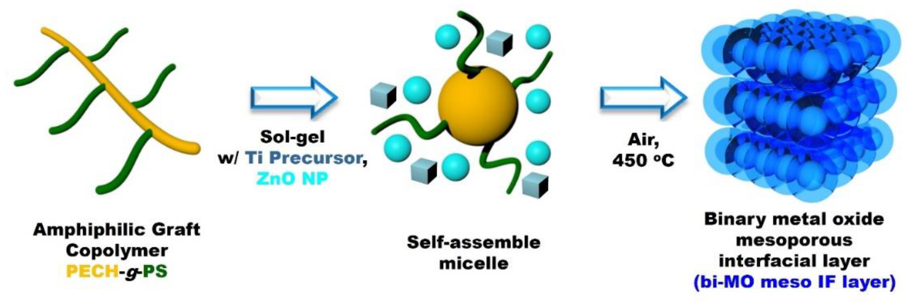
Figure 1.
XRD patterns of bi-MO meso IF layer on FTO where S, T and Z denote SnO2, TiO2 and ZnO, respectively.
Figure 1.
XRD patterns of bi-MO meso IF layer on FTO where S, T and Z denote SnO2, TiO2 and ZnO, respectively.
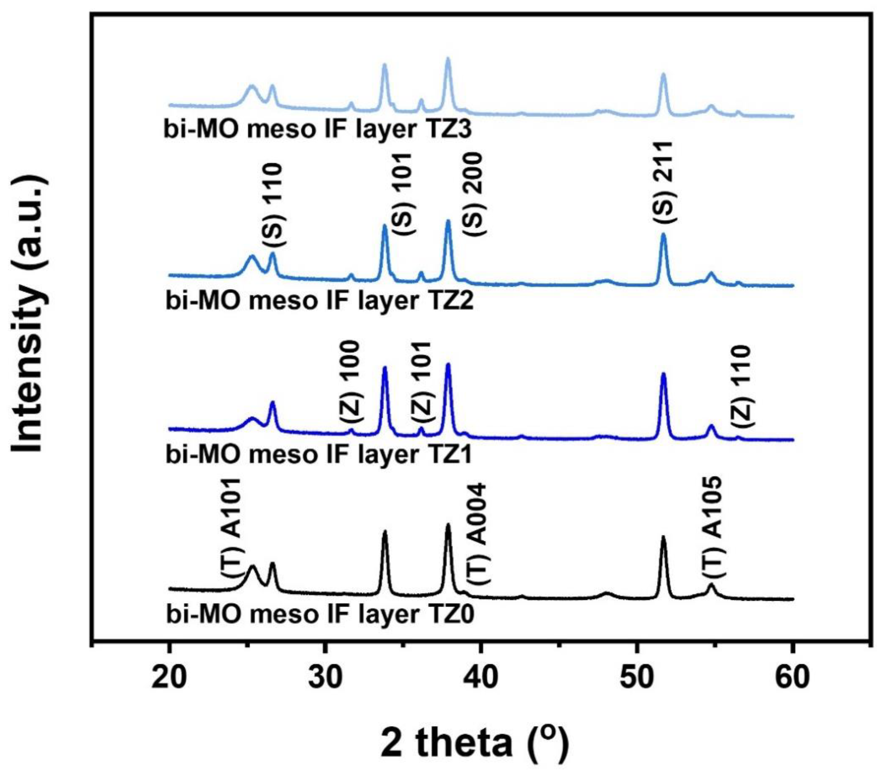
Figure 2.
FE-SEM surface images of (a) bi-MO meso IF layer TZ1, FE-SEM cross-sectional images of (b) bi-MO meso IF layer TZ1 on FTO, (c) magnified bi-MO meso IF layer TZ1 on FTO and (d) nc-TiO2 layer/bi-MO meso IF layer TZ1 on FTO.
Figure 2.
FE-SEM surface images of (a) bi-MO meso IF layer TZ1, FE-SEM cross-sectional images of (b) bi-MO meso IF layer TZ1 on FTO, (c) magnified bi-MO meso IF layer TZ1 on FTO and (d) nc-TiO2 layer/bi-MO meso IF layer TZ1 on FTO.
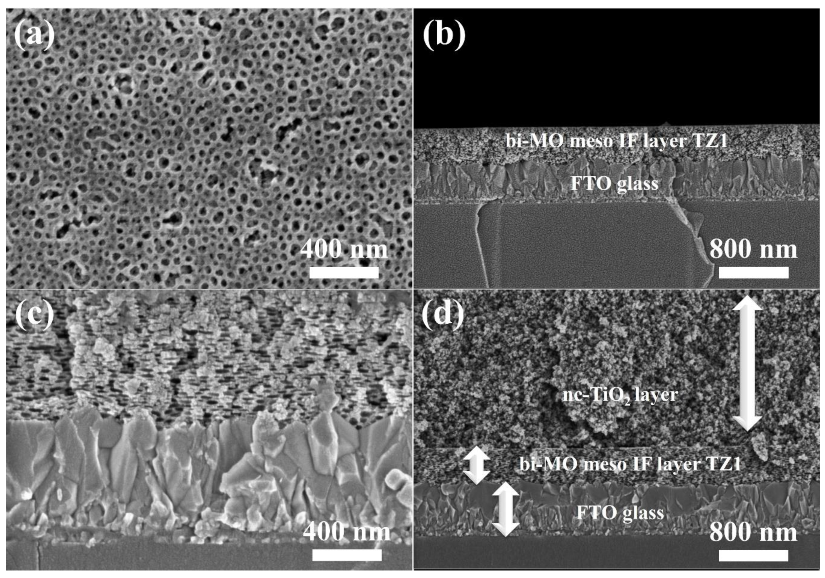
Figure 3.
Transmittance spectra of bi-MO meso IF layer on FTO, dense-TiO2 layer on FTO and pristine FTO.
Figure 3.
Transmittance spectra of bi-MO meso IF layer on FTO, dense-TiO2 layer on FTO and pristine FTO.
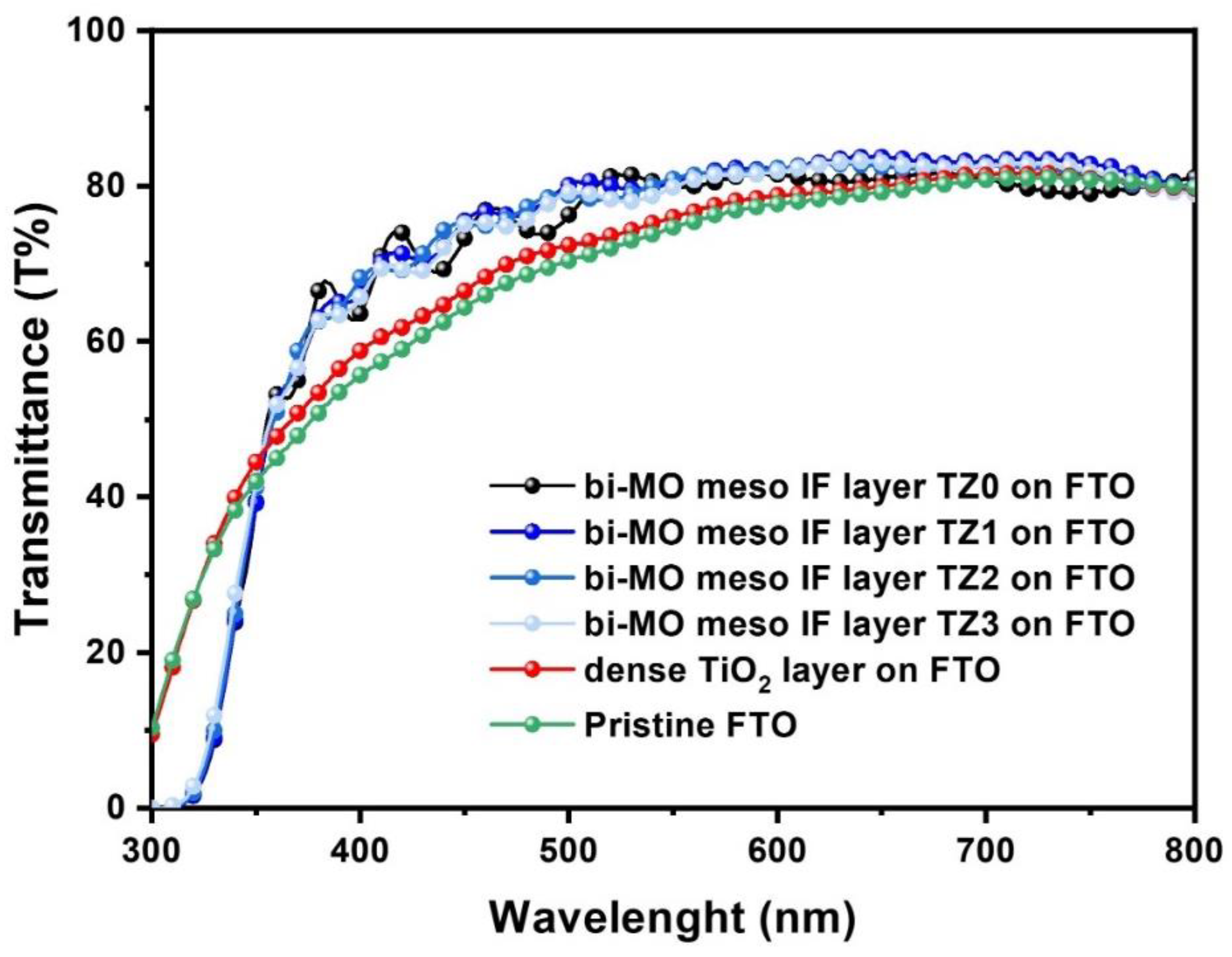
Figure 4.
(a) J-V curves, (b) EIS Nyquist plots under 1 sun condition, (c) IPCE curves of bi-MO meso IF layer based solid state photovoltaic cells and (d) Normalized cell efficiency of the bi-MO meso IF layer based solid state photovoltaic cells (40-50% relative humidity). Error bars represent the standard deviation of at least 5 cells.
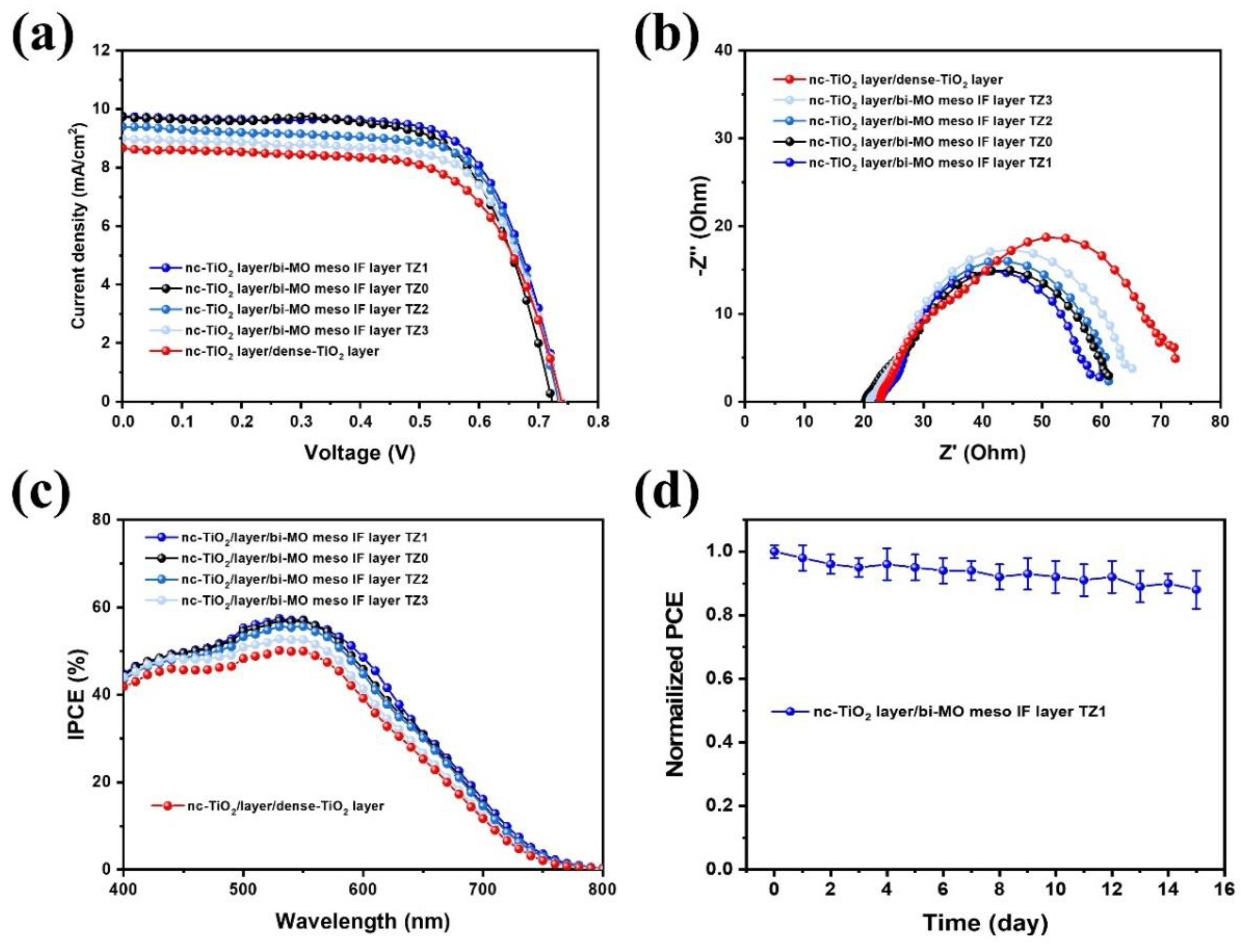

Table 1.
Photovoltaic properties of bi-MO meso IF layer based solid state photovoltaic cells at 100 mW/cm2 (AM 1.5). a, b, c, d, e, f Dye adsorption amount determined from UV-visible absorption spectra for bi-MO meso IF layer based solid state photovoltaic cells. g.
Table 1.
Photovoltaic properties of bi-MO meso IF layer based solid state photovoltaic cells at 100 mW/cm2 (AM 1.5). a, b, c, d, e, f Dye adsorption amount determined from UV-visible absorption spectra for bi-MO meso IF layer based solid state photovoltaic cells. g.
| Photoanode |
Voc (V) |
Jscd (mA/cm2) |
Jsce (mA/cm2) |
FF |
η (%) |
dye adsorption value (nmol/cm2) |
|---|---|---|---|---|---|---|
| nc-TiO2 layer /bi-MO meso IF layer TZ0 |
0.72±0.04 | 9.7±0.5 | 9.3 | 0.68±0.02 | 4.7±0.15 | 68 |
| nc-TiO2 layer /bi-MO meso IF layer TZ1 |
0.74±0.04 | 9.8±0.5 | 9.5 | 0.69±0.02 | 5.0±0.15 | 70 |
| nc-TiO2 layer /bi-MO meso IF layer TZ2 |
0.73±0.05 | 9.4±0.6 | 9.2 | 0.69±0.03 | 4.8±0.20 | 69 |
| nc-TiO2 layer /bi-MO meso IF layer TZ3 |
0.73±0.05 | 9.0±0.7 | 8.9 | 0.68±0.02 | 4.6±0.20 | 64 |
| nc-TiO2 layer /dense-TiO2 layer |
0.72±0.04 | 8.7±0.7 | 8.6 | 0.67±0.03 | 4.2±0.20 | 55 |
a Solid-state electrolyte consists of PEG, LiI, MPII, and I2 in acetonitrile. b The photoactive area for solid state photovoltaic cells was 0.16 cm2. c The thickness of the photoanode was approximately 7 μm. d Determined from J-V curves. e Determined from IPCE curves. f Error bars represent the standard deviation of at least 5 cells. g Dye adsorbed photoanode active areas were fixed at 0.16 cm2.
Table 2.
Electrochemical parameters of bi-MO meso IF layer based solid state photovoltaic, as determined by EIS analysis at 100 mW/cm2 (AM 1.5). Error bars represent the standard deviation of at least 5 cells.
Table 2.
Electrochemical parameters of bi-MO meso IF layer based solid state photovoltaic, as determined by EIS analysis at 100 mW/cm2 (AM 1.5). Error bars represent the standard deviation of at least 5 cells.
| Photoanode | Rs (Ω) |
R1 (Ω) |
R2 (Ω) |
Ws (Ω) |
|---|---|---|---|---|
| nc-TiO2 layer /bi-MO meso IF layer TZ0 |
19.9±3.0 | 9.9±1.5 | 37±5.5 | 2.4±0.3 |
| nc-TiO2 layer /bi-MO meso IF layer TZ1 |
22.2±2.8 | 9.6±1.3 | 33±4.5 | 2.1±0.1 |
| nc-TiO2 layer /bi-MO meso IF layer TZ2 |
21.8±3.1 | 9.7±1.6 | 38±5.7 | 2.4±0.2 |
| nc-TiO2 layer /bi-MO meso IF layer TZ3 |
21.0±3.0 | 9.9±1.5 | 40±5.6 | 2.6±0.2 |
| nc-TiO2 layer /dense-TiO2 layer |
23.2±3.3 | 10.1±1.8 | 43±5.8 | 3.2±0.4 |
Disclaimer/Publisher’s Note: The statements, opinions and data contained in all publications are solely those of the individual author(s) and contributor(s) and not of MDPI and/or the editor(s). MDPI and/or the editor(s) disclaim responsibility for any injury to people or property resulting from any ideas, methods, instructions or products referred to in the content. |
© 2024 by the authors. Licensee MDPI, Basel, Switzerland. This article is an open access article distributed under the terms and conditions of the Creative Commons Attribution (CC BY) license (http://creativecommons.org/licenses/by/4.0/).
Copyright: This open access article is published under a Creative Commons CC BY 4.0 license, which permit the free download, distribution, and reuse, provided that the author and preprint are cited in any reuse.


