
Submitted:
11 February 2024
Posted:
13 February 2024
You are already at the latest version
Abstract
This papers objective is to describe a method of in-office 3D designing and 3D printing of a tooth-borne molar distalizer and create a library to easily reproduce the needed distalizers in a private orthodontic clinic. Research objectives were to design and 3D print molar distalizers, clinically use in orthodontic treatment settings, assess the strength and frequency of debonding and or breakage. The print resin used was Dental LT Clear V2 (RS-F2-DLCL-02) from formlabs. The 3D printer used was a Formlabs 3B+printer. 16 patients were treated with these 3D printed distalizers. Patients selected were between 11 Years and 49 Years old, Class II occlusion with no skeletal Class II values. The skeletal cephalometric values of the six patients were within the range of SNA = 81± 3º , SNB = 78 ± 3º , ANB = 3 ± 2º. The mean duration of the 3D printed appliance was 14.58 ± 4.31 weeks. The aim reached, was to position molars and canines in a dental Class I position. The combined failure rate was 0.94. A library of distalizers has been made of sizes between 16mm and 29mm, they are easy to print and easy to use in office.
Keywords:
distalizer
; orthodontics
; digital
; biocompatible 3D printing
; dental biocompatible resin
; CAD/CAM
; computer modelling
; class II
; molar derotation
1. Introduction
In recent years 3D printing technology endured significant technological improvements [1,2,3,4,5,6,7,8,9,10]. Whereas SLA, DLP and LCD based 3D printers improved [6,7,10,11,12,13,14], 3D printing resins proved to be bio-compatible [3,9,12,14,15,16,17,18] and being able to endure masticatory forces [5,8,11,14,18,19,20]. This enabled orthodontists to set up their own 3D lab and design and print a variety of orthodontic appliances [3,9,17,21,22,23]. Class II malocclusion has an average prevalence of 20.2% [24]. Vertically, the entire range of variance can be observed, ranging from a facial form with reduced lower face height and increased overbite (hypodivergent) to a facial form with increased lower face height and reduced overbite or anterior open bite (hyperdivergent), depending on the degree of disharmony. Malocclusions linked to an elevated Frankfort–mandibular planes angle are typically more difficult to address during orthodontic treatment due to the unfavourable downward and backward trend of mandibular growth and unfavourable soft tissue pattern. The soft tissues can contribute to the development of a class II division 1 incisor relationship, especially when the upper incisors are positioned on or in front of the lower lip. This phenomenon is referred to as a lip trap and can lead to the upper incisors protruding forward and the lower incisors tilting backward, thus exacerbating the overjet. A lower lip that is highly active, causing a noticeable backward movement of the lower lip section, is referred to as ’strap-like’. The inclination of the upper incisors can also result in the protrusion of the upper lip. Lip incompetence is indicated when the lower lip rests below the upper incisors in situations with low or average angles. In this scenario, the lip connection is occasionally characterised as theoretically competent, as the only factor preventing the patient from obtaining lip competence without exertion is the positioning of their teeth. In circumstances when the angle of the face is high, lip incompetence typically occurs because the height of the lower facial skeleton is more than the length of the lip. This means that muscular effort is needed to acquire lip competence. The vertical growth pattern plays a crucial role in ensuring long-term stability after reducing overjet in these circumstances. Stability is more probable when the lower lip is positioned in front of the upper incisors following treatment. This is more likely to occur when the Frankfort-mandibular angle is average or low, and there is an accompanying anterior growth rotation. High angle class II division 1 malocclusions pose a challenge in treatment due to the combination of a backward growth rotation and increased lower face height. Even if the overjet is effectively minimised, the lower lip tends to rest below the upper incisors, further complicating the situation. Although the overjet is enlarged, the overbite can vary in severity, but is frequently incomplete due to the presence of a compensatory swallowing pattern caused by the larger overjet. Dental crowding is a common occurrence, especially in the lower front teeth if they are tilted backwards. The maxillary incisors commonly exhibit proclination and spacing as a result of the lower lip’s resting posture when a lip trap is present. The cause of a class II division 1 incisor connection is typically due to skeletal factors, specifically mandibular retrognathia. However, it can also be influenced by lip position in cases when there is a skeletal class I or, less commonly, a class III pattern. It may also be caused by a persistent habit of sucking on digits after the permanent maxillary incisors have come in. An elevated overjet can lead to adverse psychological consequences and is also linked to a higher likelihood of injury to the upper lip area, especially in youngsters. These factors indicate the need for therapy [25]. The treatment is mostly determined by the severity of the skeletal discrepancy and the contribution of the dento-alveolar region to the overjet. There are three primary methods for correcting a class II division 1 malocclusion. First of all growth modification in a patient who is still growing, efforts can be made to rectify the underlying skeletal disparity by using or altering the natural development process. This can be done through the use of headgear, a functional device, or a combination of both. The patient’s compliance with the treatment, which can be fairly rigorous, and the direction and magnitude of growth are the determining factors of success. Both of these variables are highly unpredictable. We can use a method of orthodontic camouflage correcting the overjet by moving the teeth. This is done by uprighting or retracting the upper incisors and proclining the lower incisors, while accepting the existing skeletal difference. In order to accomplish this, it is typically necessary to have sufficient space in the upper arch. This space can be achieved by either distalizing or by removing maxillary premolars. This procedure is acceptable for correcting a class II division 1 malocclusion in an individual with a skeletal class I or mild-to-moderate skeletal class II base who has stopped developing. However, it may not be useful for individuals with more severe skeletal class II discrepancies as it could have unfavourable consequences on the soft tissue profile. Combined orthodontic–surgical treatment is utilised for cases with a notable antero-posterior or vertical skeletal component in their malocclusion. When camouflage treatment is not feasible, this approach involves surgical repositioning of the jaws to achieve definitive correction of the skeletal discrepancy as part of the treatment plan.
Therefore a large variety of molar distalizing appliances have been developed over the years. In some Class II protocols for orthodontic patients with maxillary alveolar protusion, molar distalization has been proposed to avoid extraction of premolars [26]. Next we list some of these appliances. Molar distalizers exist in a variety of solutions. As there are appliances as Hilgers pendulum [27], distal jet appliance [28], modified slider [29], intraoral bodily molar distalizer [30], J-Molar Distalizer [31], Greenfield lingual distalizer [32] or simplified molar distalizer [33], which are fixed appliance connected to a plastic pad in contact with the palatal ruggae, with springs or rotary devices to distalize molars, with the advantage of not depending on patient cooperation, but the disadvantage of incisal protrusion. These have the disadvantage of disto-rotating the mandible thus increasing the anterior facial height [34,35]. Others like the Hybrid hyrax Distalizer are fabricated in metal, and skeletally anchored in the palate with the use of mini-implants, thus avoiding the disto-rotation of the mandible [36,37]. The Beneslider [38] and in succession the Longslider [39] with high pseudoelastic forces to overcome the slider friction occuring in the Beneslider are skeletally anchored as well. The appliance proposed in this article is an in office designed distalizer comparable to Carriere® Motion 3D™ (Henry Schein Orthodontics, Carlsbad, Ca, USA) [1,40,41,42,43,44,45,46,47,48,49,50,51,52,53,54,55,56,57], consisting of a rigid bar connected with a pad on the canine attached to the anterior third of the clinical crown, with a mesial hook attached to it and pivoting in a ball-and-socket joint with a pad bonded to center of the clinical crown of molar facilitating the distalization en derotation of the molar. The activation of the device is done with elastics Force 1 at 6oz. and Force 2 at 8oz., attached to a hook on the canine pad. Measuring the results are shown using CBCT [44,52,54,55], cephalometric superimposition and model [1,58] or overlay of the STL files before and after treatment [1,42]. The advantage of using a distalizer is its insertion at the beginning of the treatment, when compliance is still high. A distalizer is a low invasive, with easy placement and removal technique advantages. The real effect of a molar distalizer is molar derotation, trough the ball and socket joint, resulting in a distal vector of force, thus resulting in distalization and distal tipping of the first upper molar and distal tipping of the canine or premolar [1,44,45,47,54,55,57], on the other hand an intrusion of the upper molars can be seen and an extrusion of the canine or premolar, resulting in the clockwise rotation of the occlusal plane [1,44,45,47,54,55,56,57]. However this can add a unfavourable facial effect through further distal positioning of the mandible. This is a disadvantage for dolichocephalic patients and thus a contra-indication for dolichocephalic patients and an advantage for brachycephalic patients. Depending on the case a clockwise rotation may be favourable or unfavourable for the class 2 correction. A ‘shorty’ Carriere Motion Appliance has been created which is a shorter arm from first molar to first premolar, which is intended to reduce the occlusal plane rotational effects through closer proximity to the centre of rotation of the maxillary and mandibular dentition. Other effects are, mesialisation of lower molars and tipping of the lower incisors [1,44,45,47,54,55,56,57].A lower vacuum-formed retainer is designed to utilise the lower arch as anchorage. Mesial movement of the lower posterior teeth is not seen as a favourable feature of the Carriere Motion Appliance, and through differential anchorage between the arches, is designed to limit mesial movement of the lower posterior teeth and less proclination of the lower incisors, but not completely eliminating this movement [1,44,45,47,54,55,56,57].
2. Materials and Methods
1. Digital Design
Digital bio-compatible Additive Manufacturing (AM), brings 3D printing and manufacturing closer to a orthodontic practice, and allows for manufacturing of distalizers, power-arms, retainers and other perceivable orthodontic auxiliaries [14,17,18,21].
The bio-compatible resin chosen, Dental LT Clear, has been applied with success in orthodontic manufacturing [3,5,8,9,11,12,18,20,21]. For 3D printing we opted for a Formlabs 3B+ printer. There has been extensive research comparing 3D print technology [4,6,7,10,12,13,14,59]. These conclude that model position [13], anti-aliasing, grey-scale and blur [7,60] are the most influencing parameters. Positioning parallel to the 3D printer tray [14] is favourable and we used the anti-aliasing, grey-scale and blur settings proposed by the manufacturer. The software used is Fusion360 and 123D Design both from Autodesk™ [61]. We start the design process with a spline placed in line with a cylinder. The we change the form of the cylinder to the desired shape, then we sweep the cylinder over the spline to form the arm Figure 1. Next we cut the starting cylinder. Finally we make the rotary part of the molar hinge. This concise of a sphere with a diameter of 2.52mm, here we make indentations on the side of this ball with spheres with diameter 10mm. These indentations will allow the arm to click in place in the molar base, and will form a doughnut-and-socket joint, to allow for the derotation of the molar. A hollowed out cylinder is used to change the form of the arm on the side where the rotating part is attached to in a way that the doughnut can be easily attached to the arm without protruding parts of the arm limiting the movement in the molar pad. Then the rotating part is fitted onto the arm Figure 2.
Form a hemisphere of 6mm, change the width to 4.5mm and attach to the arm to form the canine attachment Figure 4. Another hemisphere 3.5mm is being created on top of the canine attachment to create the hook for the elastics. A cutout is made with a round edged box of 1.2 mm high and finally the top edge of the cutout has been rounded off Figure 4.
We start with a hemisphere ⊘ 7.5mm to form the molar attachment. The molar pad will be flattened on the side with 2 boxes and a large sphere ⊘ 35mm is used to form the concavity of of the molar pad. Then a cutout is made with a box, first in 90º then a second cutout in -18º Figure 4. A copy of the existing arm is enlarged 1.1 and used to make the cutout in the molar pad. After this the entrance is enlarged with a rounded edged box of 1.85 mm wide and 2.62 high to facilitate the rotation of the arm, the molar pad is ready. Figure 5.
2. Patient Selection
Patients were chosen by the following selection criteria:
- Class II occlusion with no skeletal Class II values
- Skeletal cephalometric values of SNA = 81± 3º , SNB = 78 ± 3º , ANB = 3 ± 2º ;
- Patients were compliant with dental monitoring on a monthly basis;
3. Printing
The bio-compatible resin chosen, Dental LT Clear, has been applied with success in orthodontic manufacturing [3,5,8,9,11,12,17,18,20]. Dental LT Clear resin (Formlabs Inc.) is one of the most investigated resins. Shown is that this material offers in combination with the Formlabs Form 3B+ (Formlabs Inc.) a good accuracy, a high load resistance thanks to the reversible elastic deformation [5,18], furthermore Dental LT clear material didn’t show difference in structure after compression load [8]. For 3D printing we opted for a Formlabs™Form 3B+ , as it has been validated in FDA-cleared workflows. There has been extensive research comparing 3D print technology [4,6,7,10,12,13,14,59,62,63]. These conclude that model position [9,13], anti-aliasing, grey-scale and blur [7,60] are the most influencing parameters. Positioning parallel to the 3D printer tray [14] is favourable and we used the anti-aliasing, grey-scale and blur settings proposed by the manufacturer.
4. Post-Processing after 3D Printing
After printing the distalizer Figure 7, it must be washed, and the support removed. We used a FormWash filled with a concentration of 99% IPA, to comply with bio-compatibility regulations [64]. 3D printed parts require post processing in order to ensure their optimal performance and bio-compatibility of the 3D printed dental appliances. Parts 3D printed with the Dental LT Clear V2 Resin should be first washed for 15 minutes, then soaked in fresh isopropyl alcohol for a remaining 3 minutes. Leaving the parts in the IPA for longer than 20 minutes will result in lower quality of the parts due to excessive solvent exposure [64].
Curing was done with the help of the FormCure curing chamber (60 minutes at 60 ºC).This cure setting ensures that it achieves both bio-compatibility and optimum mechanical properties Figure 8 [65]. Thanks to the preciseness of the Formlabs™Form 3B+ in combination with Dental LT Clear resin (Formlabs Inc.), it was possible to just simply click the distalizer arm into the distalizer pad without any hassle. Figure 10 shows the distalizer just out off the curing chamber, the arm already clicked inside the molar pad.
5. Testing
We build testing equipment to test the distalizers resistance to force. The first tool was a part maxilla and mandibula combination, where the mandibula could open and close, this each time 1200 cycles and this repeated as much as needed. Software was written for an arduino uno with a LCD screen and keypad, the moving force was produced through a servo motor. The whole tool was 3D printed with a Ultimaker 3 and PETG filament. The maxilla in the tool had places prepared to fix human teeth into with Impregum Penta (3M™) as this can mimic the periodontal ligament. Two human teeth were bonded into the maxilla with Impregum Penta (3M™). The 3D printed distalizer had the canine and molar bonding pads sandblasted. Then Transbond™ XT (3M Unitek)primer was applied to the pads and light cured [66]. Transbond™ XT (3M Unitek) light cure paste was used to bond the distalizer to the teeth, after the teeth were cleaned, etched and Transbond™ XT (3M Unitek) primer applied [67].Figure 10. CMA Force 1 and 2 Class II elastics were used in the test.
The second testing tool was built using an Arduino Mega and a touchscreen. The software used to drive this was written by ourselves. A stepper motor and stepper motor driver board were being attached. A worm drive was connected to the stepper motor, moving a sled on which the distalizer was attached. A load-cell of 10kg was used to measure the maximum load applied using 1/4’ 6oz. and 3/16’ 8oz. elastics Figure 11. The tool was 3D printed with a Ultimaker 3 with peg filament. No distalizers were damaged using this testing process.
6. Clinical Application
The 3D printed distalizers were prepared, sandblasting the canine and molar bonding pads. Then Transbond™ XT (3M Unitek)primer was applied to the pads and light cured [66]. Transbond™ XT (3M Unitek) light cure paste was used to bond the distalizer to the teeth, after the teeth were cleaned, etched and Transbond™ XT (3M Unitek) primer applied [67]. Before light curing excessive remnants were being removed. The activation of the molar distalizers was done with class II elastics, during testing from beginning until the end with 1/4 inch (6.35mm), 6 oz (170 g) and 3/16 inch (4.76mm), 8 oz (230 g) elastics were connected from the canine pad to a button on teeth 46 or 47 and 36 or 37 [68,69,70,71].
7. Measurements The 3D scans were made with the 3Shape TRIOS® 4 and measurements were done within the software of Medit-Link with the Medit design app (©MEDIT corp. 8, Yangpyeong-ro 25-gil, Yeongdeungpo-gu, Seoul, Republic of Korea) [72,73]. The measurements were done independent by 2 researchers, each two times with 7 days between both measurements. The distalization was measured on an overlay of the STL-file at the beginning and at the end, where a fixed point on the canines and molars in both STL’s was used. A line connecting respectively canines and molars was drawn on which the same point on canines and molars in the overlay STL were measured in distance perpendicular to the lines in the first STL.
3. Results
The objective was to propose a method of designing a molar distalizer library, and forthcoming manufacture the molar distalizers in-office as described in the digital-design chapter.
The next objective was the evaluation of failure, both breakage and debonding and thus evaluating the relative strength in vivo.
Table 1 shows the overview of 16 patients treated with these 3d printed molar distalizers. Assuming a moderate effect (d = 0.7) and a alpha error of 0.05, the sample size calculation using the G-Power analysis yields a total sample size of n = 13. In this table we list the age of participating patients, the time the distalizers have been worn, the size of distalizers used and the failure rate.
We add Table 2 for descriptive purpose. We see an age span between 11-49 years of age, a range of distalizers between 18 and 27mm. The short distalizers are those bonded from premolar to molar, the longer ones () bonded from canine to molar. The time needed to achieve a molar Class I was on average 14.6 weeks, with a total failure rate, left and right distalizer per patient combined, of 94%. On average, we see a breakage of one distalizer, left or right, per patient. The failures were breakage of the arm at the edge of the canine pad. Four of our patients had a failure on each side, while six patients had no failures at all. These failures typically were caused by eating food, specifically forbidden for the time wearing the distalizers (chocolate, popcorn, pizza crust, nuts, hard cookies). Patients admitted experimenting with the "forbidden" list, but after breakage the co-operation was much better.
The overlay results of the 3D scans show the distalisation and derotation Figure 12.
A high correlation was found between the derotation values of the left upper molar and the right upper molar ( = 0.713; p = 0.002) (Figure 14C). There is no correlation between the right upper molar distalization and the left upper molar distalization values ( = 0.214; p = 0.426) (Figure 14B), probably because of Class II elastic prescription change once a molar Class I was reached on the one side and not yet on the other side. There was a high correlation found between the right upper canine distalization values and the right upper molar distalization values ( = 0.789; p = <0.001) (Figure 13C), even though no correlation could be found between distalization values of the left upper canine and the left upper molar ( = 0.417; p = 0.108) probably because of the derotation of the molar are part of the total molar distalization value (Figure 13D). No correlation could be found between the displacement value of the upper left molar and it’s derotation angle ( = 0.139; p = 0.608) (Figure 13B), and a high correlation could be found between the displacement of the upper right molar and it’s derotation angle ( = 0.765; p = <0.001) (Figure 13A). There is a high correlation between the right upper canine distalization and the left upper canine distalization values ( = 0.630; p = 0.009) (Figure 14A).
Comparing the measuring results of the two researchers, showed with intraclass correlation coefficients (ICC) a good interindividual and intraindividual agreement (interindividual: mean ICC: 0.95, range: 0.93 - 0.98; intraindividual: mean ICC: 0.99, range: 0.990-0.993).

Table 4.
Descriptive statistics of the distal tooth displacement of upper canines (mm), upper first molars (mm), and the derotation angle of the upper first molars (°).
Table 4.
Descriptive statistics of the distal tooth displacement of upper canines (mm), upper first molars (mm), and the derotation angle of the upper first molars (°).
| n | Mean | SD 1 | Minimum | Maximum | |
|---|---|---|---|---|---|
| Upper canine displacement | 32 | 3.157 | 1.453 | 0.88 | 7.06 |
| Upper molar displacement | 32 | 2.465 | 1.336 | 0.82 | 7.06 |
| Upper molar derotation angle | 32 | 6.098 | 4.250 | 0.58 | 16.08 |
1 SD: standard deviation.
4. Discussion
The proposed method of 3D designing and 3D printing is just a new step in in-office designing and manufacturing of orthodontic devices. Fusion 360 generative design and Finite Elements Analysis, aid in designing with the use of artificial intelligence. More data of actual forces applied on distalizers, is needed to be able to build a reliable mathematical model, thus improving artificial intelligence and facilitating Additive Manufacturing. The 3D intra-oral scanners, 3D dental printers and biocompatible 3D printing resins available, facilitate the manufacturing in-office [2,12,14,59]. Even though breakage and debonding incidents were noted, they were caused by patient-admitted non-compliance during eating. Due to the transparency of the material, easy bonding by light curing was achieved. Even the replacement of a broken arm of the distalizer was fast. After removing the remains of the canine or premolar pad, the new arm can be easily clicked in the existing molar pad due to the preciseness of the 3D printing procedure. The new arm with pad can then be bonded on the vestibular surface of the canine or premolar. The results presented, show a proof of concept. Further research is ongoing to reduce breakage of the presented molar distalizers. Not part of measurements done, but we still also see distal tipping of upper molars and upper canines or premolars as part of the distalization. We didn’t measure the incisal tipping nor the lower molar mesialisation. Our measurements were aimed at measuring the relative distalization. As 3D intra-oral scanners and 3D printers flood the modern dental clinics, as materials improve and already offer a vast array of dental treatment solutions, research will remain ongoing. 3D printing of clear aligners [3,22], power arms [74], other appliances [17], unilateral used distalizers [21], splints [9] or in-office 3D printing of orthodontic brackets [23] all have already been proven feasible. Thanks to easily accessible software like 123D Design and its successor Fusion 360 from Autodesk™,TinkerCAD , FreeCAD — open source free 3D modeling software, Google™SketchUp or Meshmixer from Autodesk™3D design is readily available. Additive Manufacturing poses a challenge to the current and future generation of general practitioners and orthodontists alike. Adding 3D design and manufacturing to the dental curriculum could be interesting.
5. Conclusions
The results show the creation of a library of 3D printed distalizers, sizes 16-29mm, with the possibility of changing form and size at any time, to be able to personalise the distalizer there where needed. The library not only concises of readily distalizers, but also contains the four main structural parts, being, The canine/premolar pad, the arm, the rotational part on the arm and finally the molar pad. There was an acceptable failure rate, even though full compliance can never be reached and yet distalization and derotation capabilities comparable to CMA [1,21,40,41,42,47,48,50,51,52,54,56,58,75]. We would like to remind once more that since the distalization of the upper canine/premolar and upper molar and extrusion of the upper canine/premolar results in a clockwise rotation of the occlusal plane. This type of distalizer is more suitable for patients with a horizontal or neutral growth pattern, and contraindicated for patients with a vertical growth pattern. Further development and research will be done to enhance the strength of the distalizers, thus reducing the failure rate.
Author Contributions
Conceptualization, S.B. ; methodology, S.B.; software, S.B. and S.T.; validation, S.B. and S.T.; formal analysis, S.B. and S.T.; investigation, S.B.; resources, S.B.; data curation, S.B. and S.T.; writing—original draft preparation, S.B.; writing—review and editing, S.B.; visualization, S.B. and S.T.; supervision, S.B.; project administration, S.B. Both authors have read and agreed to the published version of the manuscript.
Funding
No funding, grants or other support was received.
Institutional Review Board Statement
The study was conducted according to the guidelines of the Declaration of Helsinki, no approval was necessary by the Ethics Committee. Ethical review and approval were waived for this study, due to the fact that no experimental materials or approaches were used. All used materials are fully certified and are available in the market. Dental LT Clear (V2) is certified as bio-compatible per EN-ISO 10993-1:2009/AC:2010. The bio-compatible resin material follows ISO Standards: EN-ISO 1641:2009, EN-ISO 10993-1:2009/AC:2010, EN-ISO 10993-3:2009, EN-ISO 10993-5:2009, EN 908:2008.Formlabs electrical equipment is manufactured in facilities with the following QMS certifications. Form 3B+ (Quality system standards) ISO 9001:2015 and ISO 14001:2015.
Informed Consent Statement
Written informed consent was obtained from all subjects involved in this study.
Data Availability Statement
Data available in a publicly available repository, this data is available here [https://drive.google.com/drive/folders/1ASH5q6cuZN6bNKHy_dzt_xntl5_JRNkM?usp=sharing].
Acknowledgments
We acknowledge the support of Tandartsenpraktijk ProDenta BV for the use of the lab infrastructure.
Conflicts of Interest
The authors declare no conflicts of interest.
Abbreviations
The following abbreviations are used in this manuscript:
| MDPI | Multidisciplinary Digital Publishing Institute |
| DOAJ | Directory of open access journals |
| CMA | Carriere motion appliance |
| AM | Additive Manufacturing |
| ICC | Intraclass Correlation Coefficients |
References
- Schmid-Herrmann, C.U.; Delfs, J.; Mahaini, L.; Schumacher, E.; Hirsch, C.; Koehne, T.; Kahl-Nieke, B. Retrospective investigation of the 3D effects of the Carriere Motion 3D appliance using model and cephalometric superimposition. Clin Oral Investig 2023, 27, 631–643. [Google Scholar] [CrossRef]
- Eliades, T.; Zinelis, S. Three-dimensional printing and in-house appliance fabrication: Between innovation and stepping into the unknown. Am J Orthod Dentofacial Orthop 2021, 159, 1–3. [Google Scholar] [CrossRef]
- Tartaglia, G.M.; Mapelli, A.; Maspero, C.; Santaniello, T.; Serafin, M.; Farronato, M.; Caprioglio, A. Direct 3D printing of clear orthodontic aligners: Current state and future possibilities. Materials 2021, 14, 1799. [Google Scholar] [CrossRef]
- Jiang, T.; Yan, B.; Jiang, M.; Xu, B.; Xu, Y.; Yu, Y.; Ma, T.; Wang, H. Enhanced Adhesion-Efficient Demolding Integration DLP 3D Printing Device. Applied sciences 2022, 12, 7373. [Google Scholar] [CrossRef]
- Paradowska-Stolarz, A.; Malysa, A.; Mikulewicz, M. Comparison of the Compression and Tensile Modulus of Two Chosen Resins Used in Dentistry for 3D Printing. Materials 2022, 15, 8956. [Google Scholar] [CrossRef]
- Tsolakis, I.A.; Papaioannou, W.; Papadopoulou, E.; Dalampira, M.; Tsolakis, A.I. Comparison in Terms of Accuracy between DLP and LCD Printing Technology for Dental Model Printing. Dentistry journal 2022, 10, 181. [Google Scholar] [CrossRef]
- Montgomery, S.M.; Demoly, F.; Zhou, K.; Qi, H.J. Pixel-Level Grayscale Manipulation to Improve Accuracy in Digital Light Processing 3D Printing. Advanced functional materials 2023. [Google Scholar] [CrossRef]
- Paradowska-Stolarz, A.; Wieckiewicz, M.; Kozakiewicz, M.; Jurczyszyn, K. Mechanical Properties, Fractal Dimension, and Texture Analysis of Selected 3D-Printed Resins Used in Dentistry That Underwent the Compression Test. Polymers 2023, 15, 1772. [Google Scholar] [CrossRef] [PubMed]
- Revilla-León, M.; Cascos-Sánchez, R.; Zeitler, J.M.; Barmak, A.B.; Kois, J.C.; Gómez-Polo, M. Influence of print orientation and wet-dry storage time on the intaglio accuracy of additively manufactured occlusal devices. The Journal of prosthetic dentistry 2023. [Google Scholar] [CrossRef] [PubMed]
- Vlasa, A.; Bocanet, V.I.; Muntean, M.H.; Bud, A.; Dragomir, B.R.; Rosu, S.N.; Lazar, L.; Bud, E. Accuracy of Three-Dimensional Printed Dental Models Based on Ethylene Di-Methacrylate-Stereolithography (SLA) vs. Digital Light Processing (DLP). Applied sciences 2023, 13, 2664. [Google Scholar] [CrossRef]
- Marcel, R.; Reinhard, H.; Andreas, K. Accuracy of CAD/CAM-fabricated bite splints: milling vs 3D printing. Clinical oral investigations 2020, 24, 4607–4615. [Google Scholar] [CrossRef]
- Barone, S.; Neri, P.; Paoli, A.; Razionale, A.V.; Tamburrino, F. Development of a DLP 3D printer for orthodontic applications. Procedia Manufacturing 2019, 38, 1017–1025. [Google Scholar] [CrossRef]
- Yao, L.; Hu, P.; Wu, Z.; Liu, W.; Lv, Q.; Nie, Z.; Zhengdi, H. Comparison of accuracy and precision of various types of photo-curing printing technology. Journal of Physics: Conference Series 2020, 1549, 32151. [Google Scholar] [CrossRef]
- Farkas, A.Z.; Galatanu, S.V.; Nagib, R. The Influence of Printing Layer Thickness and Orientation on the Mechanical Properties of DLP 3D-Printed Dental Resin. Polymers 2023, 15, 1113. [Google Scholar] [CrossRef]
- Schuster, M.; Turecek, C.; Mateos, A.; Stampfl, J.; Liska, R.; Varga, F. Evaluation of Biocompatible Photopolymers II: Further Reactive Diluents. Monatshefte fur Chemie 2007, 138, 261–268. [Google Scholar] [CrossRef]
- Alifui-Segbaya, F.; Varma, S.; Lieschke, G.; George, R. Biocompatibility of Photopolymers in 3D printing. Addit. Manuf. 2017, 4, 185–191. [Google Scholar] [CrossRef]
- Thurzo, A.; Sufliarsky, B.; Urbanova, W.; Cverha, M.; Strunga, M.; Varga, I. Pierre Robin Sequence and 3D Printed Personalized Composite Appliances in Interdisciplinary Approach. Polymers 2022, 14, 3858. [Google Scholar] [CrossRef]
- Goracci, C.; Juloski, J.; D’Amico, C.; Balestra, D.; Volpe, A.; Juloski, J.; Vichi, A. Clinically Relevant Properties of 3D Printable Materials for Intraoral Use in Orthodontics: A Critical Review of the Literature. Materials 2023, 16, 2166. [Google Scholar] [CrossRef]
- Chen, S.; Yang, J.; Jia, Y.G.; Lu, B.; Ren, L. Study of a 3D-Printable Reinforced Composite Resin: PMMA Modified with Silver Nanoparticles Loaded Cellulose Nonocrystal. Materials 2018, 11. [Google Scholar] [CrossRef]
- Aretxabaleta, M.; Xepapadeas, A.B.; Poets, C.F.; Koos, B.; Spintzyk, S. Fracture load of an orthodontic appliance for robin sequence treatment in a digital workflow. Materials 2021, 14, 1–17. [Google Scholar] [CrossRef]
- Thurzo, A.; Urbanová, W.; Novák, B.; Waczulíková, I.; Varga, I. Utilization of a 3D Printed Orthodontic Distalizer for Tooth-Borne Hybrid Treatment in Class II Unilateral Malocclusions. Materials 2022, 15, 1740. [Google Scholar] [CrossRef] [PubMed]
- Lee, S.; Kim, H.; Kim, H.; Chung, C.J.; Choi, Y.; Kim, S.J.; J-Y, C. Thermo-mechanical properties of 3D printed photocurable shape memory resin for clear aligners. Sci Rep 2022, 12. [Google Scholar] [CrossRef] [PubMed]
- Papageorgiou, S.; Polychronis, G.; Panayi, N.e.a. New aesthetic in-house 3D-printed brackets: proof of concept and fundamental mechanical properties. Prog Orthod. 2022, 23. [Google Scholar] [CrossRef] [PubMed]
- Cenzato, N.; Nobili, A.; Maspero, C. Prevalence of Dental Malocclusions in Different Geographical Areas: Scoping Review. Dent J (Basel) 2021, 9. [Google Scholar] [CrossRef] [PubMed]
- Q.V., N.; Bezemer, P.; Habets, L.; Prahl-Andersen, B. A systematic review of the relationship between overjet size and traumatic dental injuries. Eur J Orthod.. 1999, 21, 503–15. [CrossRef] [PubMed]
- Nanda, R.; Garino, F.; Ojima, K.; Castroflorio, T.; Parrini, S. Chapter 12: The hybrid approach in class II malocclusions treatment. In Principles and Biomechanics of Aligner Treatment- E-Book, 1st ed.; Vol. 1, Elsevier Health Sciences, 2021; pp. 149–160.
- Hilgers, J.J. The pendulum appliance for Class II non-compliance therapy. J Clin Orthod 1992, 26, 706–14. [Google Scholar] [PubMed]
- Kinzinger, G.S.; Diedrich, P.R. Biomechanics of a Distal Jet appliance. Theoretical considerations and in vitro analysis of force systems. Angle Orthod 2008, 78, 676–81. [Google Scholar] [CrossRef] [PubMed]
- Sayinsu, K.; Isik, F.; Allaf, F.; Arun, T. Unilateral molar distalization with a modified slider. European journal of orthodontics 2006, 28, 361–365. [Google Scholar] [CrossRef] [PubMed]
- Keles, A.; Sayinsu, K. A new approach in maxillary molar distalization: Intraoral bodily molar distalizer. American journal of orthodontics and dentofacial orthopedics 2000, 117, 39–48. [Google Scholar] [CrossRef]
- Batra, P.; Ragini, R. The J-Molar Distalizer for bodily molar movement. Journal of clinical orthodontics 2014, 48, 312–315. [Google Scholar]
- Greenfield, R.L. The Greenfield lingual distalizer. Journal of clinical orthodontics 2005, 39, 548–56. [Google Scholar]
- Walde, K.C. The simplified molar distalizer. Journal of clinical orthodontics 2003, 37, 616–9. [Google Scholar]
- Ghosh, J.; Nanda, R.S. Evaluation of an intraoral maxillary molar distalization technique. Am J Orthod Dentofacial Orthop 1996, 110, 639–46. [Google Scholar] [CrossRef]
- Byloff, F.K.; Darendeliler, M.A.; Clar, E.; Darendeliler, A. Distal molar movement using the pendulum appliance. Part 2: The effects of maxillary molar root uprighting bends. Angle Orthod 1997, 67, 261–70. [Google Scholar] [CrossRef]
- Clarenbach, T.H.; Wilmes, B.; Ihssen, B.; Vasudavan, S.; Drescher, D. Hybrid hyrax distalizer and mentoplate for rapid palatal expansion, class III treatment, and upper molar distalization. Journal of clinical orthodontics 2017, 51, 317–325. [Google Scholar]
- Graf, S.; Vasudavan, S.; Wilmes, B. CAD/CAM Metallic Printing of a Skeletally Anchored Upper Molar Distalizer. Journal of clinical orthodontics 2020, 54, 140–150. [Google Scholar]
- Longerich, U.J.J.; Thurau, M.; Grill, F.; Stimmer, H.; Gahl, C.M.; Kolk, A. Does molar distalization by the Beneslider have skeletal and dental impacts? A prospective 3D analysis. Oral surgery, oral medicine, oral pathology and oral radiology 2022, 134, 36–48. [Google Scholar] [CrossRef]
- Longerich, U.J.J.M.D.D.D.S.; Thurau, M.M.D.D.D.S.; Kolk, A.M.D.D.D.S.P. Development of a new device for maxillary molar distalization with high pseudoelastic forces to overcome slider friction: the Longslider—a modification of the Beneslider. ORAL SURGERY ORAL MEDICINE ORAL PATHOLOGY ORAL RADIOLOGY 2014, 118, 22–34. [Google Scholar] [CrossRef]
- Carrière, L. A new Class II distalizer. Journal of clinical orthodontics 2004, 38, 224–231. [Google Scholar]
- Luca, L.; Francesca, C.; Daniela, G.; Alfredo, S.G.; Giuseppe, S. Cephalometric analysis of dental and skeletal effects of Carriere Motion 3D appliance for Class II malocclusion. Am J Orthod Dentofacial Orthop 2022, 161, 659–665. [Google Scholar] [CrossRef]
- Nercellas Rodriguez, A.; Colino Gallardo, P.; Zubizarreta-Macho, A.; Colino Paniagua, C.; Alvarado Lorenzo, A.; Albaladejo Martinez, A. A New Digital Method to Quantify the Effects Produced by Carriere Motion Appliance. J. Pers. Med. 2023, 13. [Google Scholar] [CrossRef]
- Rodriguez, H.L. Long-Term Stability of Two-Phase Class II Treatment with the Carriere Motion Appliance. J Clin Orthod 2019, 53, 481–487. [Google Scholar]
- Wilson, B.; Konstantoni, N.; Kim, K.B.; Foley, P.; Ueno, H. Three-dimensional cone-beam computed tomography comparison of shorty and standard Class II Carriere Motion appliance. Angle Orthod 2021, 91, 423–432. [Google Scholar] [CrossRef] [PubMed]
- Areepong, D.; Kim, K.B.; Oliver, D.R.; Ueno, H. The Class II Carriere Motion appliance. Angle Orthod 2020, 90, 491–499. [Google Scholar] [CrossRef]
- Fouda, A.S.; Attia, K.H.; Abouelezz, A.M.; El-Ghafour, M.A.; Aboulfotouh, M.H. Anchorage control using miniscrews in comparison to Essix appliance in treatment of postpubertal patients with Class II malocclusion using Carriere Motion Appliance. Angle Orthod 2022, 92, 45–54. [Google Scholar] [CrossRef]
- Clermont, A.; Albert, A.; Bruwier, A. Effects of the Class II Carriere motion appliance in phase I treatment: A randomized controlled trial. J Clin Orthod 2022, 56, 285–293. [Google Scholar] [PubMed]
- Areepong, D.; Kim, K.B.; Oliver, D.R.; Ueno, H. The Class II Carriere Motion appliance. Angle Orthod 2020, 90, 491–499. [Google Scholar] [CrossRef]
- Fouda, A.S.; Aboulfotouh, M.H.; Attia, K.H.; Aboulezezz, A.M. Carriere Motion Appliance with Miniscrew Anchorage for Treatment of Class II, Division 1 Malocclusion. J Clin Orthod 2020, 54, 633–641. [Google Scholar]
- Barakat, D.; Bakdach, W.M.M.; Youssef, M. Treatment effects of Carriere Motion Appliance on patients with class II malocclusion: A systematic review and meta-analysis. Int Orthod 2021, 19, 353–364. [Google Scholar] [CrossRef]
- Lombardo, L.; Cremonini, F.; Oliverio, T.; Cervinara, F.; Siciliani, G. Class II correction with Carriere Motion 3D Appliance and clear aligner therapy. J Clin Orthod 2022, 56, 187–193. [Google Scholar]
- Attia, K.H.; Aboulfotouh, M.F.A. Three-dimensional computed tomography evaluation of airway changes after treatment with Carriere Motion 3D Class II appliance. J Dent Maxillofacial Res. 2019, 2, 16–19. [Google Scholar]
- Malinowski, K.; Chodur, M.; Majewski, M.; Malinowski, J. Age dependent treatment response to the Carriere Motion 3D appliance for the correction of Class II malocclusion. Journal of Education, Health and Sport 2022, 12, 169–177. [Google Scholar] [CrossRef]
- Hashem, A.S. Thre dimensional assessment of the long-term treatment stability after maxillary first molar distalisation with Carriere distalizer appliance. Life Sci J 2020, 17, 83–90. [Google Scholar]
- Nasef, A.; Refai, W. Application of a New Three Dimensional Method of Analysis for Comparison between the Effects of Two Different Methods of Distalisation of the Maxillary First Molar. Egypt Dent J 2015, 61, 4195–4201. [Google Scholar]
- Kim-Berman, H.; McNamara, J.A..J.; JP, L.; McMullen, C.; Franchi, L. Treatment effects of the Carriere Motion 3D appliance for the correction of Class II maloccludion in adolescents. Angle Orthod. 2019, 89, 839–846. [Google Scholar] [CrossRef]
- Ghozy, E.A.; Albelasy, N.F.; Shamaa, M.S.; El-Bialy, A.A. Cephalometric and digital model analysis of Dentoskeletal effects of Infrazygomatic miniscrew vs. Essix- anchored Carriere Motion appliance for distalization of maxillary buccal segment: A randomized clinical trial. BMC Oral Health. 2024, 24. [Google Scholar] [CrossRef]
- Yin, K.; Han, E.; Guo, J.; Yasumura, T.; Grauer, D.; Sameshima, G. Evaluating the treatment effectiveness and efficiency of Carriere Distalizer: a cephalometric and study model comparison of Class II appliances. Prog Orthod 2019, 20, 24. [Google Scholar] [CrossRef]
- Deng, W.; Xie, D.; Liu, F.; Zhao, J.; Shen, L.; Tian, Z. DLP-Based 3D Printing for Automated Precision Manufacturing. Mobile information systems 2022, 2022, 1–14. [Google Scholar] [CrossRef]
- liqcreate. Explained & tested: Anti-Aliasing (AA) and Blur in resin 3D-printing, 2023.
- Federici Canova, F.; Oliva, G.; Beretta, M.; Dalessandri, D. Digital (R)Evolution: Open-Source Softwares for Orthodontics. Appl. Sci. 2021, 11. [Google Scholar] [CrossRef]
- Formlabs Form 3B+ printer. https://media.formlabs.com/m/759db40c7c05b049/original/-ENUS-Form-3B-manual.pdf.
- Sarker, S.; Colton, A.; Wen, Z.; Xu, X.; Erdi, M.; Jones, A.; Kofinas, P.; Tubaldi, E.; Walczak, P.; Janowski, M.; et al. 3D-Printed Microinjection Needle Arrays via a Hybrid DLP-Direct Laser Writing Strategy. Advanced materials technologies 2023, 8, n. [Google Scholar] [CrossRef]
- Form Wash Manual. https://media.formlabs.com/m/11c8523a56138d6/original/-ENUS-Form-Wash-Manual.pdf.
- Form Cure Time and Temperature Settings. https://s3.amazonaws.com/servicecloudassets.formlabs.com/med ia/Finishing/Post-Curing/115001414464-Formettings.pdf.
- Espinar-Escalona, E.; Barrera-Mora, J.M.; Llamas-Carreras, J.M.; Solano-Reina, E.; Rodriguez, D.; Gil, F.J. Improvement in adhesion of the brackets to the tooth by sandblasting treatment. J Mater Sci Mater Med 2012, 23, 605–11. [Google Scholar] [CrossRef] [PubMed]
- Scribante, A.; Gallo, S.; Turcato, B.; Trovati, F.; Gandini, P.; Sfondrini, M.F. Fear of the Relapse: Effect of Composite Type on Adhesion Efficacy of Upper and Lower Orthodontic Fixed Retainers: In Vitro Investigation and Randomized Clinical Trial. Polymers (Basel) 2020, 12. [Google Scholar] [CrossRef]
- Yilmaz, B.; Kara, M.; Seker, E.; Yenidunya, D. Do we know how much force we apply with latex intermaxillary elastics? Apos Trends in Orthodontics 2021, 11, 191–197. [Google Scholar] [CrossRef]
- Castroflorio, T.; Sedran, A.; Spadaro, F.; Rossini, G.; Cugliari, G.; Quinzi, V.; Deregibus, A. Analysis of Class II Intermaxillary Elastics Applied Forces: An in-vitro Study. Frontiers in Dental Medicine 2022, 2. [Google Scholar] [CrossRef]
- Saccomanno, S.; Quinzi, V.; Paskay, L.; Caccone, L.; Rasicci, L.; Fani, E.; Di Giandomenico, D.; Marzo, G. Evaluation of the Loss of Strength, Resistance, and Elasticity in th Different Types of Intraoral Orthodontic Elastics (IOE): A Systematic Review of the Literature of In Vitro Studies. J. Pers. Med. 2023, 13. [Google Scholar] [CrossRef]
- Dubovska, I.; Lickova, B.; Voborna, I.; Urbanova, W.; Kotova, M. Force of Intermaxillary Latex Elastics from Different Suppliers: A Comparative In Vitro Study. Appl. Sci. 2023, 13. [Google Scholar] [CrossRef]
- Medit Link Software. https://www.meditlink.com/home.
- Stefanelli, L.; Franchina, A.; Pranno, A.; Pellegrino, G.; Ferri, A.; Pranno, N.; Di Carlo, S.; De Angelis, F. Use of Intraoral Scanners for Full Dental Arches; Could Different Strategies or Overlapping Software Affect Accuracy. Int. Journal of Environmental Research and Public Health 2021, 18, 13. [Google Scholar] [CrossRef]
- Thurzo, A.; Kociš, F.; Novák, B.; Czako, L.; Varga, I. Three-Dimensional Modeling and 3D Printing of Biocompatible Orthodontic Power-Arm Design with Clinical Application. Appl. Sci. 2021, 11. [Google Scholar] [CrossRef]
- Martel, D. The Carriere Distalizer: simple and efficient. Int J Orthod Milwaukee 2012, 23, 63–6. [Google Scholar]
Figure 1.
First a spline is formed, a flattened cylinder is attached to the spline, the face of the flattened cylinder is swept over a preformed spline to form the arm.
Figure 1.
First a spline is formed, a flattened cylinder is attached to the spline, the face of the flattened cylinder is swept over a preformed spline to form the arm.

Figure 2.
The cylinder is then cut off, a cylinder formed an flattened and hollowed out on it’s poles by spheres, and the attached as part of the molar hinge.
Figure 2.
The cylinder is then cut off, a cylinder formed an flattened and hollowed out on it’s poles by spheres, and the attached as part of the molar hinge.

Figure 3.
A hemisphere is formed to construct the canine/premolar pad and this part is then attached to the arm.
Figure 3.
A hemisphere is formed to construct the canine/premolar pad and this part is then attached to the arm.
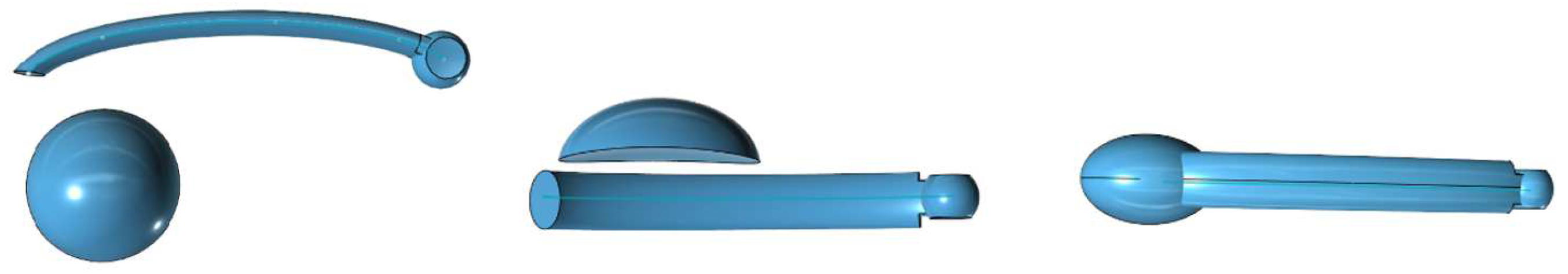
Figure 4.
Another hemisphere is then made, cut out with a box form, and attached on the canine/premolar pad
Figure 4.
Another hemisphere is then made, cut out with a box form, and attached on the canine/premolar pad
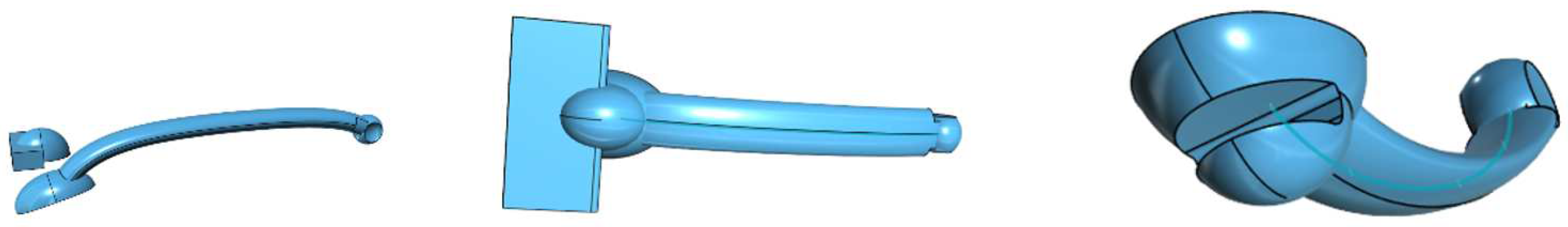
Figure 5.
To form the molar pad, we draw a sphere and cut it with a large sphere to design the rounded bottom of the molar pad. This part is the flattened on both sides with boxes. A box cut is the made to start the entrance of the arm.
Figure 5.
To form the molar pad, we draw a sphere and cut it with a large sphere to design the rounded bottom of the molar pad. This part is the flattened on both sides with boxes. A box cut is the made to start the entrance of the arm.
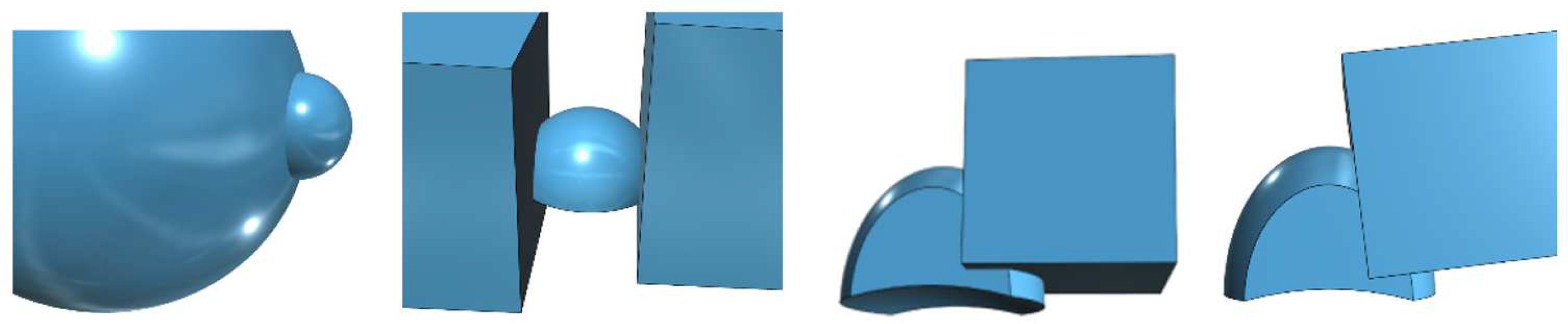
Figure 6.
With the arm 1.1 time enlarged prepare the cutout in the molar pad. Then make a cutout to allow the rotation of the arm in the molar pad.
Figure 6.
With the arm 1.1 time enlarged prepare the cutout in the molar pad. Then make a cutout to allow the rotation of the arm in the molar pad.
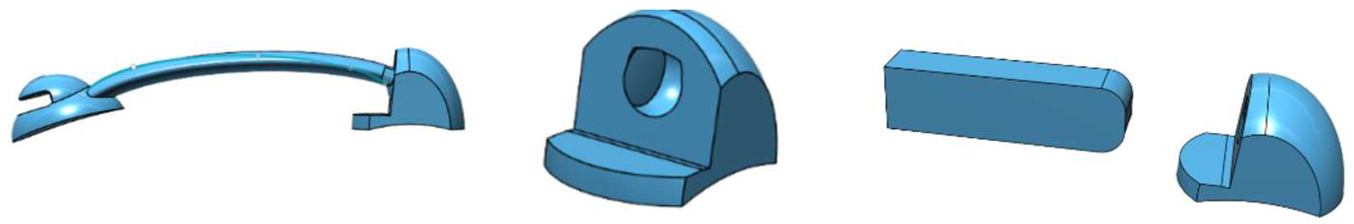
Figure 7.
The finished molar pad, and the finished distalizer.
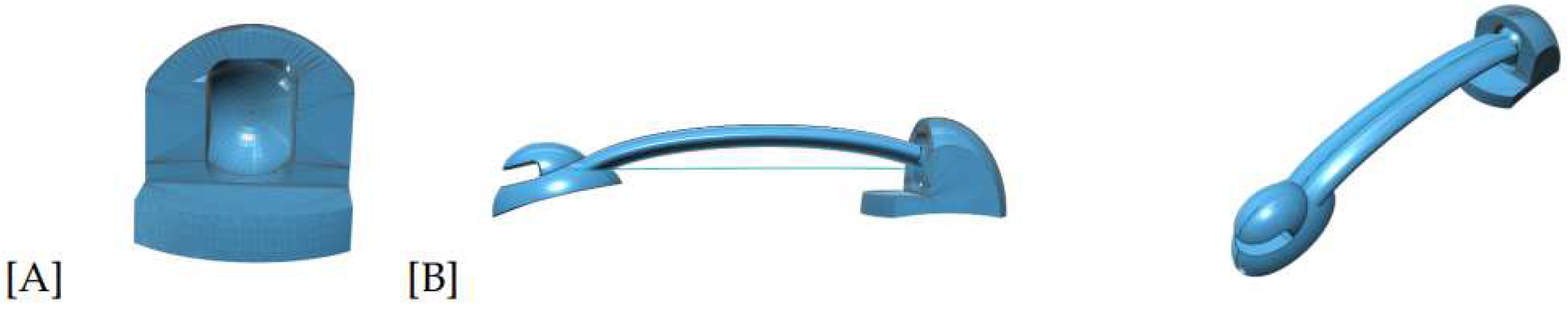
Figure 8.
The distalizers on the print plate; the distalizers in the washer; the distalizers after post cure.
Figure 8.
The distalizers on the print plate; the distalizers in the washer; the distalizers after post cure.
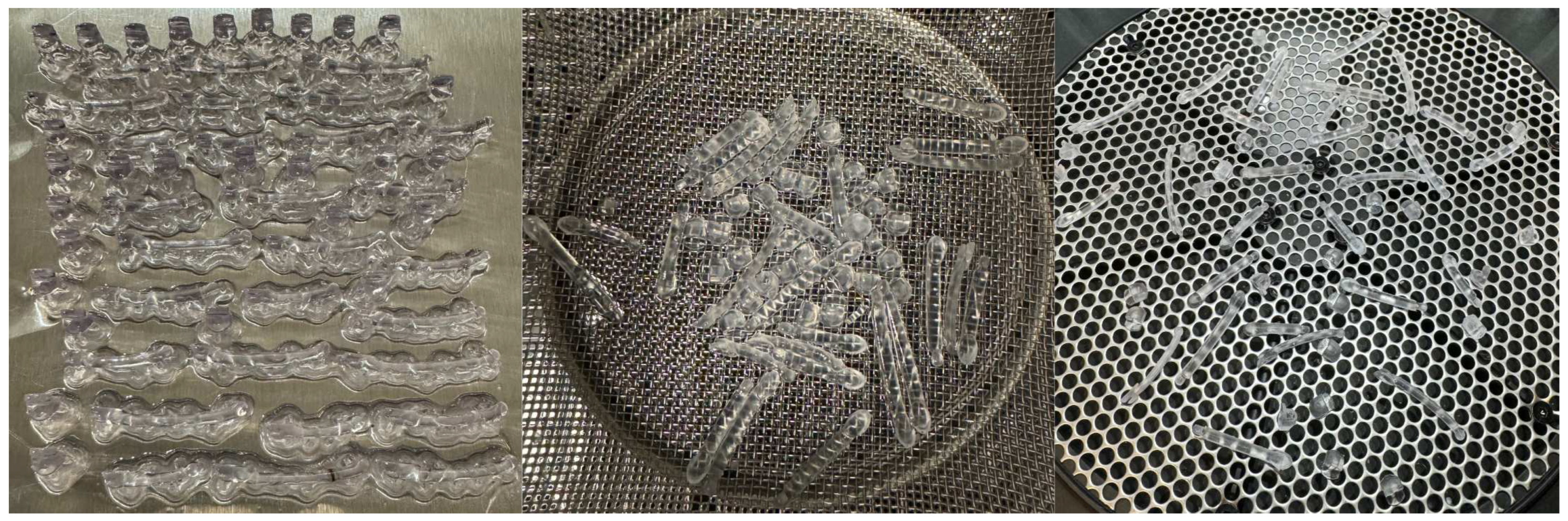
Figure 9.
Motions in sizes 16-29mm, after curing.
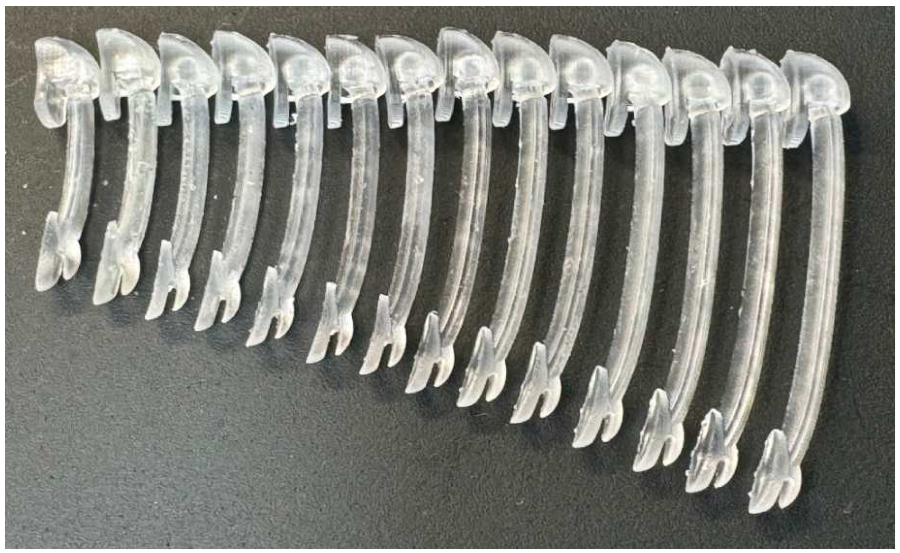
Figure 10.
3D printed cyclic distalizer tester.
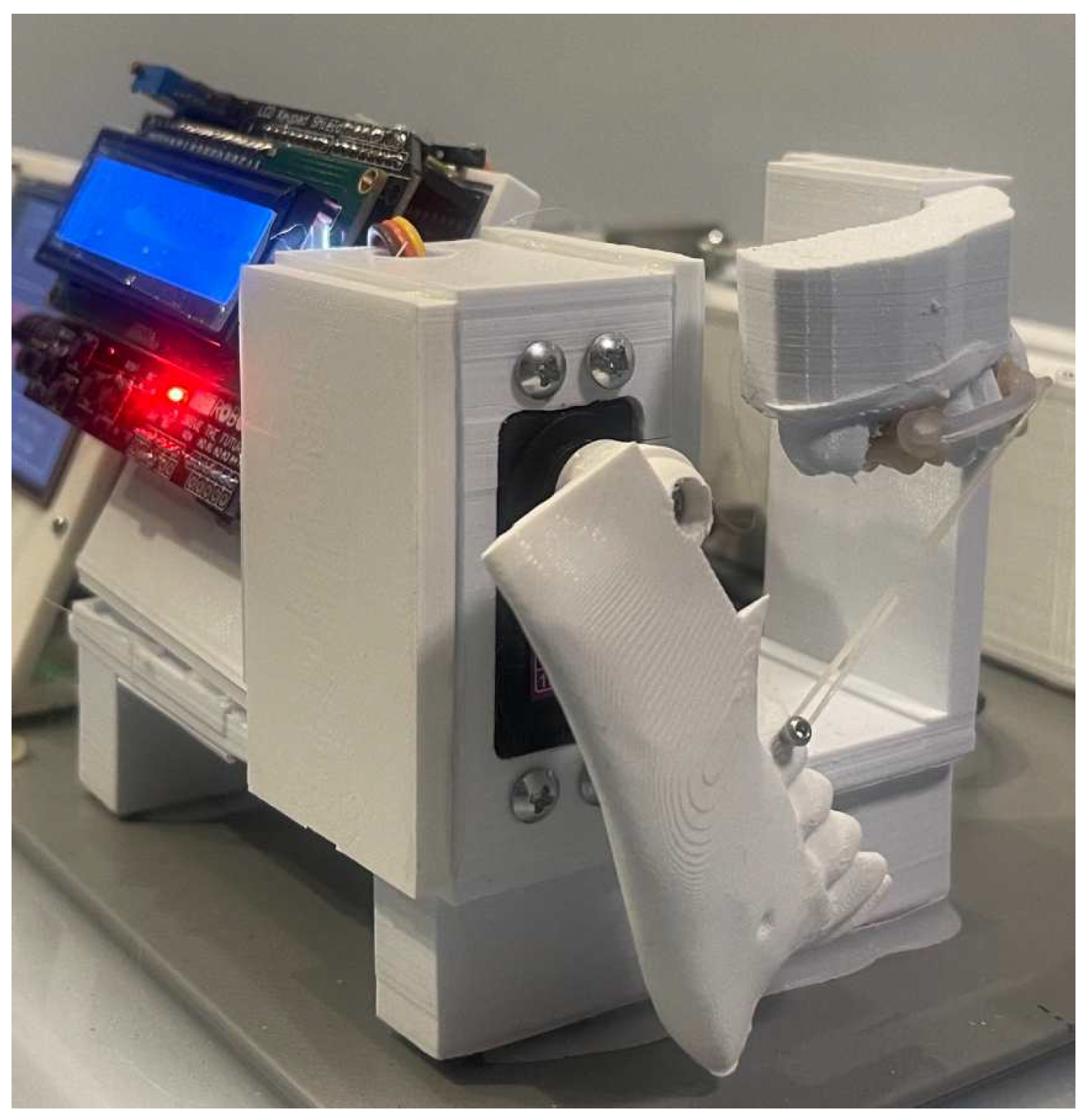
Figure 11.
3D printed strain tester.
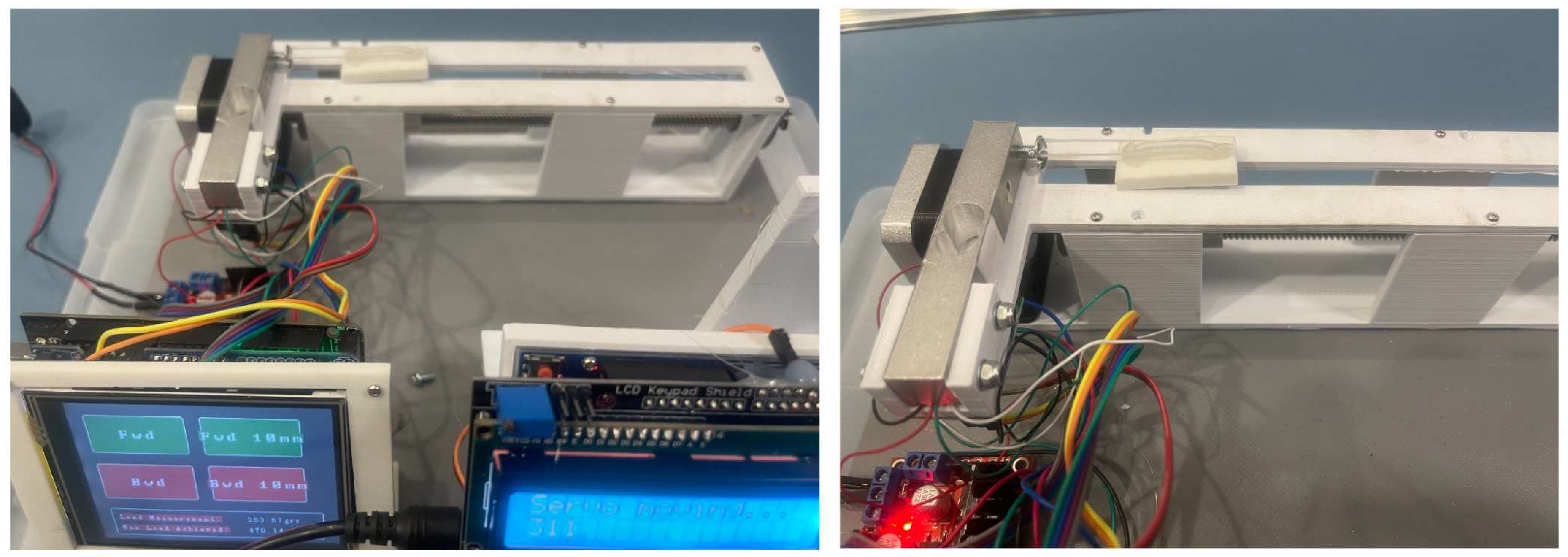
Figure 12.
The overlays of the 16 patients.
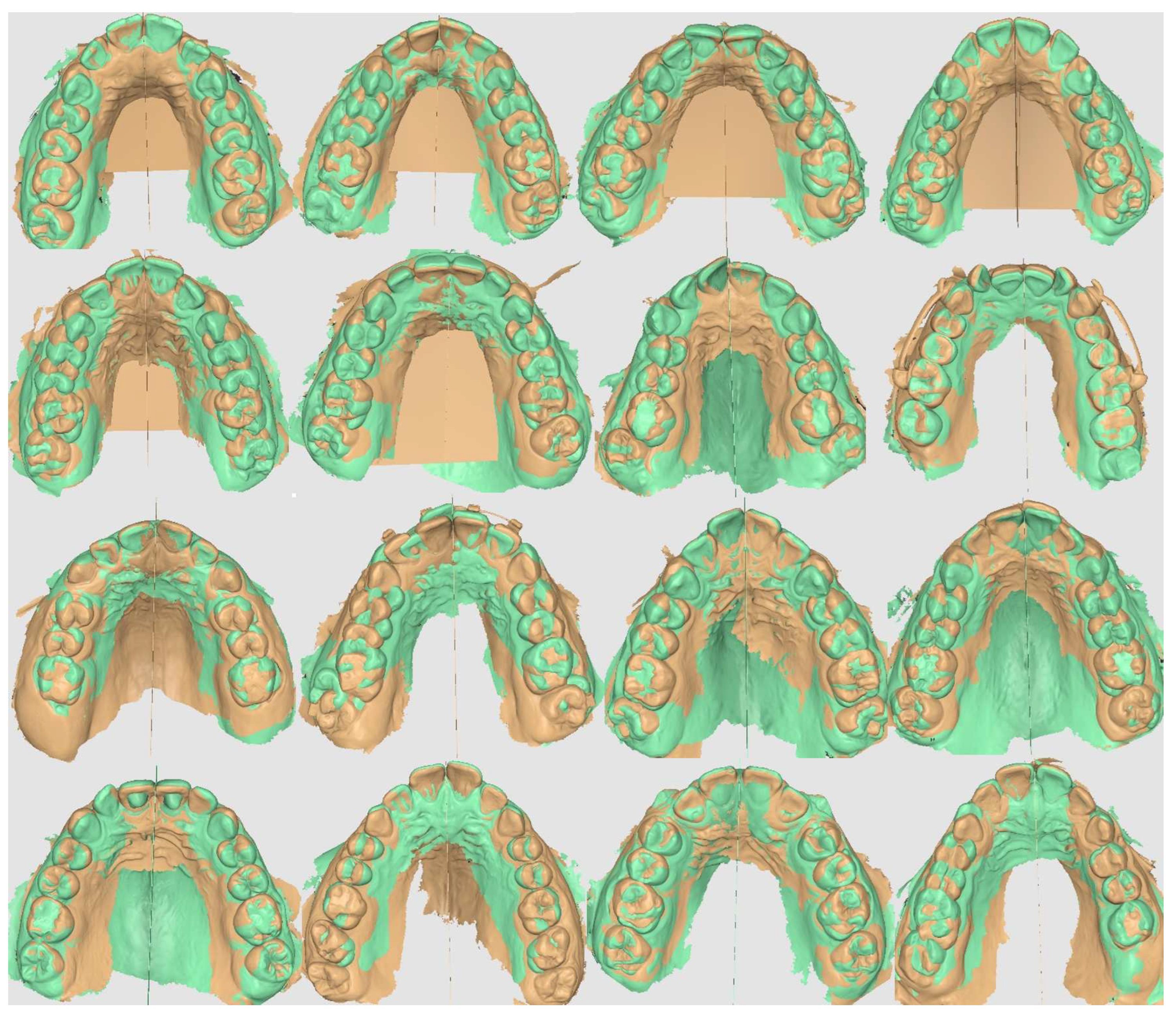
Figure 13.
[A] Fit plot of right upper molar derotation and distalization; [B] Fit plot of left upper molar derotation and distalization; [C] Fit plot of right upper canine and molar distalization; [D] Fit plot of left upper canine and molar distalization
Figure 13.
[A] Fit plot of right upper molar derotation and distalization; [B] Fit plot of left upper molar derotation and distalization; [C] Fit plot of right upper canine and molar distalization; [D] Fit plot of left upper canine and molar distalization
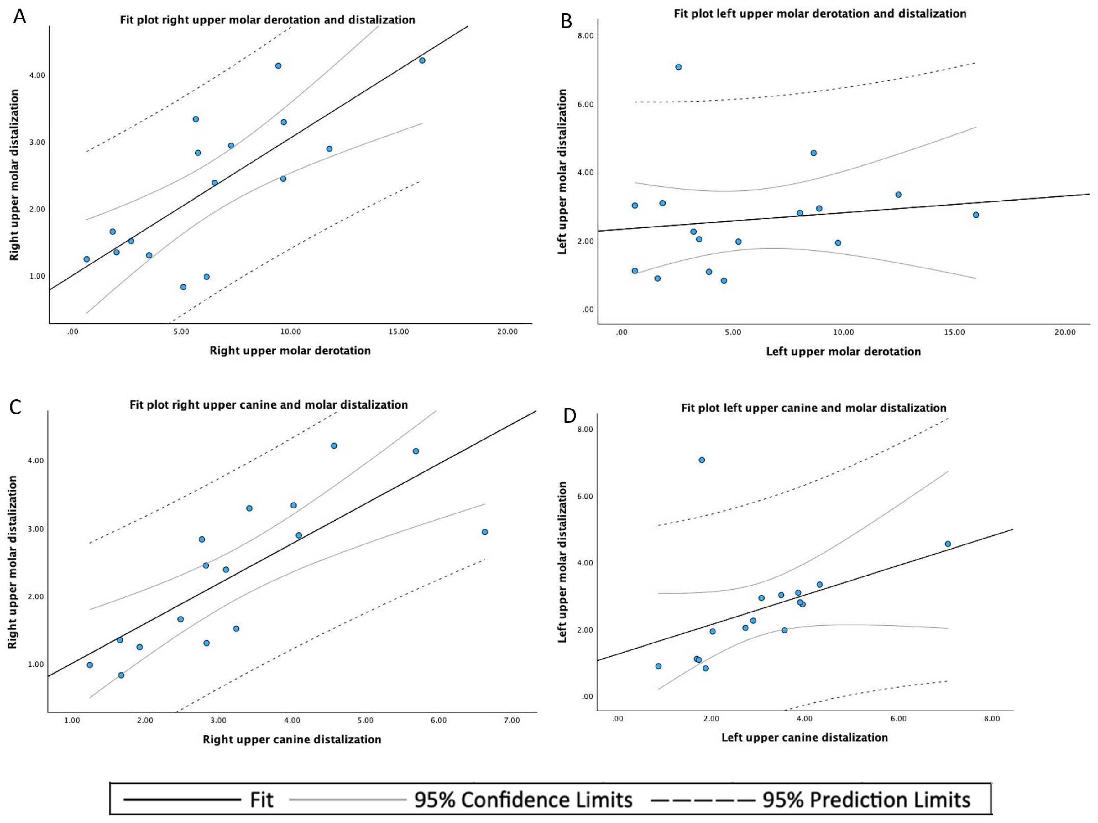
Figure 14.
[A] Fit plot of the upper canine distalization; [B] Fit plot of the upper molar distalization; [C] Fit plot of the upper molar derotation
Figure 14.
[A] Fit plot of the upper canine distalization; [B] Fit plot of the upper molar distalization; [C] Fit plot of the upper molar derotation
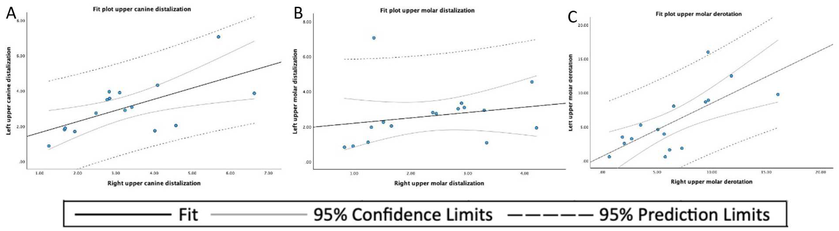
Table 1.
Results of clinical evaluation.
| ID | Age in Decimals | Time Worn | Size Right | Size Left | Failure | Failure |
|---|---|---|---|---|---|---|
| # | [years] | [weeks] | [mm] | [mm] | # | # |
| 1 | 14.95 | 16.71 | 25 | 25 | 0 | 0 |
| 2 | 14.95 | 16.71 | 25 | 25 | 1 | 0 |
| 3 | 12.62 | 11.57 | 25 | 25 | 0 | 0 |
| 4 | 15.41 | 17.71 | 26 | 27 | 1 | 0 |
| 5 | 11.74 | 17.57 | 26 | 26 | 0 | 1 |
| 6 | 14.28 | 9.14 | 24 | 25 | 0 | 0 |
| 7 | 17.91 | 13.57 | 24 | 24 | 0 | 0 |
| 8 | 49.34 | 14.00 | 26 | 26 | 1 | 1 |
| 9 | 12.94 | 11.29 | 19 | 19 | 1 | 1 |
| 10 | 14.92 | 17.14 | 27 | 27 | 1 | 1 |
| 11 | 14.11 | 10.00 | 26 | 26 | 0 | 1 |
| 12 | 11.89 | 24.86 | 26 | 26 | 1 | 0 |
| 13 | 15.41 | 10.29 | 25 | 25 | 1 | 1 |
| 14 | 14.06 | 19.57 | 24 | 25 | 0 | 0 |
| 15 | 13.07 | 9.86 | 18 | 18 | 0 | 0 |
| 16 | 15.34 | 13.29 | 24 | 24 | 0 | 1 |
Table 2.
Descriptive analysis.
| Variable | Statistics or Category | Values |
|---|---|---|
| Age [years] | mean ± SD 1 | 16.43 ± 8.91 |
| median (range) | 14.60 (11.74 - 49.34) | |
| Size [mm] | median (range) | 25.00 (18.00 - 27.00) |
| Time worn [weeks] | mean ± SD | 14.58 ± 4.31 |
| median (range) | 13.79 (9.14 - 24.86) | |
| Total failures 2 | mean | 0.94 |
1 SD: standard deviation; 2 Data of left and right distalizers combined for each individual patient.
Table 3.
Descriptive statistics of the distal tooth displacement, left and right, of the upper canines (mm), upper first molars (mm), and the derotation angle of the upper first molars (°).
Table 3.
Descriptive statistics of the distal tooth displacement, left and right, of the upper canines (mm), upper first molars (mm), and the derotation angle of the upper first molars (°).
| Mean | SD 1 | Minimum | Maximum | |
|---|---|---|---|---|
| Left upper canine displacement | 3.054 | 1.476 | 0.88 | 7.06 |
| Right upper canine displacement | 3.620 | 1.471 | 1.24 | 6.63 |
| Left upper molar displacement | 2.597 | 1.565 | 0.82 | 7.06 |
| Right upper molar displacement | 2.333 | 1.097 | 0.83 | 4.21 |
| Left upper molar derotation angle | 5.711 | 4.488 | 0.58 | 15.98 |
| Right upper molar derotation angle | 6.484 | 4.108 | 0.63 | 16.08 |
1 SD: standard deviation.
Disclaimer/Publisher’s Note: The statements, opinions and data contained in all publications are solely those of the individual author(s) and contributor(s) and not of MDPI and/or the editor(s). MDPI and/or the editor(s) disclaim responsibility for any injury to people or property resulting from any ideas, methods, instructions or products referred to in the content. |
© 2024 by the authors. Licensee MDPI, Basel, Switzerland. This article is an open access article distributed under the terms and conditions of the Creative Commons Attribution (CC BY) license (http://creativecommons.org/licenses/by/4.0/).
Copyright: This open access article is published under a Creative Commons CC BY 4.0 license, which permit the free download, distribution, and reuse, provided that the author and preprint are cited in any reuse.


