Submitted:
22 January 2024
Posted:
23 January 2024
You are already at the latest version
Abstract
This paper presents the second stage of a tandem fixed wing unmanned aerial vehicle (UAV) aerodynamic development. In the initial stage, the UAV was optimized analyzing its characteristics only in symmetrical flight conditions. Posted requirements were that both wings should produce relevant positive lift, the initial stall must occur on the front wing first, the center of pressure should be close to the center of gravity, while longitudinal static stability should be in the optimum range. Computational fluid dynamics (CFD) analyses were performed, where applied calculation model was derived from the authors’ previous successful projects. The eight version TW V8 has satisfied all longitudinal requirements. Lateral-directional CFD analyses of V8 showed that the ratio of the lateral and directional stability at the nominal cruising regime was optimal, but both lateral and directional static stabilities were too high. On further development versions the lower vertical tail was eliminated, negative dihedral was implemented on the front wing, and four inverted blended winglets were added. Version TW V14 has largely improved lateral and directional stability characteristics, while their optimum ratio at cruising regime was preserved. Longitudinal characteristics were also well preserved. Maximum lift coefficient and lift-to-drag ratio were increased, compared to the V8.
Keywords:
unmanned aerial vehicle UAV
; tandem wing
; CFD calculations
; lateral-directional aerodynamic optimization
; artificial intelligence AI knowledge database
1. Introduction
Nowadays the remote and/or automatic controlled unmanned aerial vehicles have not only replaced piloted aircraft in many roles, but have also become involved in missions and flight profiles that would be either too risky for men flying an aircraft, or manned aircraft would not be able to perform them for various reasons, mostly due to the human factor. Authors of this paper have recently been involved in the research project of a multi-purpose UAV [1], with intended weight and speed of an advanced ultralight aircraft, but smaller in size. It was supposed to be applicable for various duties, such as terrain mapping and photo reconnaissance, ground traffic observation and control, agricultural applications, and be capable of carrying customized stores, equipment and payloads for the variety of other applications.
Insights in vast amount of available references such as [2,3,4,5,6,7,8,9] support decision of the authors of this paper to finally adopt the tandem wing (TW) configuration for the new UAV; more detailed explanations considering the key aspects of this decision can be found in [1]. With estimated maximum mass of 400 kg and fuselage length of 3.8 m, it was supposed to be powered by four electric motors mounted on the front and the rear wing, powering four tractor-type propellers. Two cruising flight regimes were considered. Nominal regime implied fast cruise - low level flight (FC/LL) at the speed of 250 km/h and theoretically, for calculation purposes, at the sea level (zero altitude). The second – economical (EC) cruising regime assumed flight at speeds that would correspond to the maximum lift-to-drag ratio, at low and medium altitudes. Calculations have shown that the speed that would correspond to the EC regime is of the order of 160 km/h at the sea level. The envelope defined by the speed range 160 ÷ 250 km/h and by the altitude range 0 ÷ 5000 m was considered sufficient for most of the possible multi-purpose applications.
The initial UAV’s configuration TW V1 had the front and the rear wing of the same size. Optimization of this configuration, performed considering longitudinal analyses for the symmetrical flow conditions is described in details in [1]. It led to a completely different TW V8 geometry (Figure 1).
The TW V8 has fulfilled all the design requirements posted during the longitudinal analyses, which can be summarized as follows:
- In FC/LL flight both V8 wings generate the same amount of lift, while at EC flight regime front wing produces about 70% of the lift generated by the rear wing. In that sense the V8 geometry, which has noticeably smaller front wing than V1, is still a tandem wing, and not a canard configuration.
- The center of pressure (CP) of the V8 is very close to its center of gravity (CG) which has been estimated at 1.7 m from the fuselage nose, requiring very small trim forces at all flight regimes, except at negative angles of attack which are not expected in operational use. This CG position has been, to a first approximation, assumed to be the same for all considered TW modifications.
- At FC/LL regime the V8’s longitudinal static stability of 9.5% is small-to-moderate (corresponding jet trainer aircraft [10]), enabling sufficiently high longitudinal maneuverability for terrain avoidance at low altitudes. At EC regime it is 20.8% (corresponding to the business jets category [10]), enabling inherently more stable cruising flight, with lower actuator power consumption.
- Up to the maximum operational fuselage angle of attack = 10°, the front wing wake passes bellow the rear wing, preserving its efficiency at all flight regimes.
- Initial flow separation (stall) on V8 occurs first on the front wing, at angle of attack of = 7°, while on rear wing it happens at = 10°. This generates a natural stall recovery tendency, without the influence of flight controls. The eventual opposite tendency (rear wing stalls first) would most probably lead to an irrecoverable deep stall.
During all CFD analyses and modifications leading from TW V1 to TW V8 configuration, lateral-directional issues were considered only by the authors’ previous project experiences, without any actual numerical verifications. This practically meant that sizing of the lower and the upper vertical tails and dihedral angles of the front and the rear wing were estimated and assigned to enable efficient oncoming modifications that would lead to equally good lateral-directional results, but without degrading already well established longitudinal characteristics. CFD analyses that lead to presently latest modification TW V14 are described in the following chapters. Lateral-directional calculations of the V8 have shown that the ratio of its lateral-directional stability derivatives at the nominal FC/LL cruising regime was optimal, but their actual derivative values were beyond their optimum range limits, showing that V8 was too stable in both the lateral and directional sense. Following step-by-step modifications were carefully introduced to define the trends, or gradients of how certain aerodynamic geometry modifications were affecting these two derivatives.
The latest present outcome TW V14 has preserved optimal lateral-directional stability derivatives ratio of the V8, but with lateral and directional stability characteristics substantially improved. All V8’s well established longitudinal flying characteristics were preserved, while maximum lift coefficient and lift-to-drag ratios were even slightly increased. Further optimization of V14’s blended inverted winglets, as well as the evaluation of the control surface sizing and their influence on the longitudinal and lateral-directional performances will be analyzed within the next design steps.
2. Computational Methods
From the very beginning of this TW UAV project [1] it was clear that the application of analytical calculation tools for the optimization of quite unconventional UAV configuration, although this should be the first step in aerodynamic design, might be problematic considering the reliability and accuracy of the results, and possibly misleading at the key stages of the project development. Application of wind tunnel tests for the preliminary analyses were also excluded as an option, because a possible large number of required modifications could easily stop the work due to the exceed budget, which was limited to the professor/doctoral students’ research project level. This turned out to be true estimate, because to the present state, TW has evolved through 14 development versions, and 4 sub-versions not taken into official account. Because of that, the decision was made to start the aerodynamic optimization of the TW V1 using viscous CFD analyses in ANSYS Fluent software [11,12,13].
To enable full compatibility of the results during the entire TW’s aerodynamic project development, it was mandatory to apply the same calculation procedure settings used in longitudinal analyses for its lateral-directional optimizations as well. For the consistency of this manuscript, some important issues of the calculation algorithm described in [1] are briefly repeated here. In the longitudinal analyses with implied symmetrical flow conditions, it is a common practice to perform all analyses using half, instead of full models, with the symmetry condition assigned at the plane of symmetry. This way, results obtained for one half of the aircraft geometry and control volume are simply mirrored to the other side. For TW V1 to V8 calculations, unstructured half model meshes were generated, with number of elements ranging from 1.600.000 to 2.000.000 elements, depending on the actual version (Figure 2. - above). For the asymmetrical lateral-directional calculations, full models had to be used, where for TW V8 to V14 unstructured meshes of about 3.000.000 elements were generated (Figure 2. - bellow).
Computational model in Fluent was established based on the authors’ previous relevant projects and works where, to mention a few, CFD results were compared: (a) with the other relevant computational and design tools within a light piston engined trainer aircraft development [14,15]; with available wind tunnel test data for a supersonic fighter jet [16]; with data obtained in flight tests of a jet trainer aircraft [17], etc. All calculations were performed using RANS (Reynolds-Averaged Navier-Stokes) equations with k-ω SST turbulent model [11,12,18], provided stable convergence of the solutions. The Reverse Cuthill-McKee method [13] was used for initial reordering of the mesh, Full Multi-Grid (FMG) solution initialization at 4 levels [12,13] was applied, while the convergence was controlled by the Courant number optimization.
In this TW analyses, usual forms of aerodynamic coefficient equations for single wing aircraft [10,19] had to be customized for tandem wing calculations. The reference area for a single wing aircraft is its projected aerodynamic planform area (including its fictive portion under the fuselage) S, while for TW is denoted as and represents the sum of the front and rear wing aerodynamic areas:
The mean aerodynamic chord or MAC is used as the reference length in calculations of the pitching moment coefficient; for TW analyses it was obtained by area averaging of the front and rear wing’s MAC values:
The same applies for the wing span b, used as the reference length in calculations of the rolling and yawing moment coefficients:
Using notations: L – for the lift force, D – for the drag force, Y – for the side force, Lroll – for the rolling moment about CG, M – for the pitching moment about CG, and N – for the yawing moment about CG, their aerodynamic coefficients were calculated as:
where in equations (4)-(9), represents dynamic pressure for the given analyses, m2, m and m.
Initial verifications of the full model calculation algorithm were done: (a) by comparing the results for TW V8 lift, drag and pitching moment coefficients obtained within longitudinal analysis with those obtained by the half model [1] (Table 1) and, (b) by comparing calculated values of six aerodynamic coefficients obtained by full model at sideslip angles = ± 5° and = ± 10° (Table 2 and Figure 3).
For all calculations, the fuselage angle of attack = 5°, that corresponds to the TW V8’s maximum lift-to-drag ratio (Figure 15) has been selected, although any other within the operational range would lead to quite similar conclusions. From Table 1 it is obvious that relative differences between the and the values obtained by the two models (0.02 % and 0.11 %) are negligible. The TW V8 pitching moment coefficient at this angle of attack is ≈ 0 (also see Figure 15), while calculated values are very small and very close to this value, thus determination of their relative difference was not done.
Theoretically speaking, absolute values of aerodynamic coefficients at sideslip angles of = ± 5° and of = ± 10° and the same angle of attack should be exactly the same, with the same or opposite sign, depending on the actual coefficient. Due to the inevitable numerical errors, this is not possible. In this particular case, Figure 3 and Table 2 indicate that their relative differences are very small, with 7 out of 12 being under 1 %, while the two largest are of the order of 3 % which is, based on the authors’ previous experiences, acceptable for practical engineering applications.
Prior to any operational optimization analyses, such verifications should always be done when switching from half model to full model calculations. In some cases, relative differences presented in Table 1 and Table 2 can be noticeably larger, and often indicate that some of the assigned calculation options, and/or mesh generation algorithm settings should be revised.
3. Lateral-Directional Optimization and Results
3.1. Lateral-directional analyses of the TW V8
After calculation model verifications described in previous chapter, the full model algorithm was applied for the TW V8 lateral-directional analyses. Results obtained for moment coefficients and are presented in Figure 4 (a).
For all lateral-directional analyses the sideslip angle = + 5° was selected, which by the convention is positive when the free stream flow comes in from the right wing direction [20,21]). As shown in Table 2 and Figure 3, dependances and for TW V8 are linear functions in the whole = ± 10° domain. In order to obtain the lateral static stability derivative (or dihedral effect), and the directional static stability derivative , verification calculations for angles = - 5°, = + 10° and = + 10° were considered unnecessary. This way, derivatives were calculated as and . Taking into account conclusions from Table 2, and , and calculated lateral stability derivative has unit [1/°]. Accordingly , etc. An aircraft is laterally statically stable when and directionally statically stable when [20,21]. From Figure 4 (b) it is obvious that TW V8 is both laterally and directionally stable. In order to quantify these derivatives, boundaries or range of their recommended optimum values had to be adopted.
It is known that the contemporary computerized control systems on modern advanced aircraft and UAVs, with powerful and superfast actuators can easily provide precise guiding and control of both too stable and unstable flying vehicles. On the other hand, on manned aircraft without computer guided controls, stability and control characteristics must be very carefully examined and adjusted, depending on the aircraft’s category and purpose. The logic applied in [1], within the TW’s longitudinal optimization process, was based on the requirement that this UAV should posses inherent (natural) longitudinal static stability like a hand-flown manned aircraft. This would provide lower workload and power consumption of the actuators and flight control system, and thus enable longer flight endurance and range. The same reasoning was applied in lateral-directional optimizations.
For TW V8’s nominal (FC/LL) cruising Mach number M = 0.2 (corresponding to V = 250 km/h at H = 0 m), for the derivative, the recommended range in reference [20] is between ≈ 0.001 [1/°] (“suggested goal values”) and ≈ 0.002 [1/°] (“NASA TN D-423”). On the other hand, in [21] the upper limit is same, but lower limit is relaxed to about 0.0005 [1/°]. The authors have decided to accept the [1/°] as the optimum range for TW directional static stability evaluations.
For the derivative no recommended range is explicitly provided, since it changes as a function of the lift coefficient [20] (and accordingly, angle of attack). As a rule of thumb, both previously mentioned references suggest that for a selected relevant flight regime, optimum ratio between the lateral and directional static stability derivatives should be . Based on this recommendation, the range [1/°] for TW’s lateral stability was formally established. Keeping in mind that inevitably increases towards higher negative values with the increase of , the derivative is expected to be within this range predominantly in the vicinity of the nominal FC/LL cruising regime.
These values were used in Figure 4 (b) as horizontal boundaries, while angles of attack ≈ 0° (nominal cruise) and = 5° (economical cruise) as vertical, defining the optimum zones of interest for and . Unfortunately, both of these derivatives were way above their optimum zones by absolute values, meaning that V8 was both laterally and directionally too stable. The “good news” was that their ratio at the nominal cruise regime was almost exactly optimal as Figure 4 (c) shows. That was quite irrelevant, because it was obvious that V8 had to be subjected to further geometry modifications in order to improve its lateral-directional aerodynamic characteristics, by which the optimal ratio at FC/LL regime could likely be lost.
3.2. Lateral-directional optimization steps
In modern engineering world, many successful technical optimizations have been accomplished using genetic algorithms (GA), and recently the artificial intelligence (AI), and this applies for the aviation industry as well. These contemporary methods can efficiently provide convergence for very complex multiple degree of freedom problems, but they are most often very time and resource demanding. An opposite extreme to them are trial and error methods where, for example due to the insufficient understanding of certain physical phenomena, blind attempts are repeated until the final satisfactory solution is obtained (or not). Historically speaking, this approach has initially contributed do the growth of the general scientific knowledge, where instead of guessing, dozens of optimization methods and approaches have been developed, with precisely controlled convergence of the solutions.
In [1] and in this paper, a kind of a “manual” gradient method was implemented in TW optimizations. Well understanding the general influence of important aircraft geometry parameters (such as lifting surface area, distance from CG, dihedral angle, etc.) on certain aerodynamic parameters, after initial calculations, relevant geometry was altered and changes in coefficients/derivatives, flow patterns, CP, etc. were observed. Knowing their desired optimums, geometry variations were revised (interpolated or extrapolated), and calculations repeated. The five posted quantitative and qualitative requirements within the longitudinal TW optimizations [1], briefly described in the introduction of this manuscript, were fully satisfied reasonably quickly, within 8+2 geometry modifications, finishing with TW V8 version. Such optimization technique requires caution, but also experience and solid background knowledge and understanding of the investigated aerodynamic phenomena, or otherwise gradient method can easily turn to a trial and error approach, with unpredictable outcome. Also, authors of this paper strongly believe that here presented gradient method can provide a very useful knowledge database for higher level optimizations using advanced AI methodology.
All TW lateral-directional modifications were supposed to be done in a way to preserve well established longitudinal characteristics of the V8. In that sense, the front and the rear wing positions, areas, spans, taper ratios [1], front wing incidence +5° and rear wing incidence +1°, both without twist, as well as the NACA 652-415 [22] wing airfoil, had to remain unchanged. As in case of the V8 analyses, lateral and directional calculations were done for the sideslip angle = + 5°. Maximum operational angle of attack used in lateral-directional calculations was up to = 9° (in symmetrical cases it was = 10°), because asymmetric flow due to sideslip triggered local separation effects earlier (Figure 14). Geometry modifications TW V9 ÷ V14 are shown in Figure 5, Figure 6 and Figure 7, their moment coefficients and in Figure 8, derivatives and in Figure 9, and their ratios in Figure 10.
Evolution of each of the new TW versions developed during lateral-directional analyses are explained consecutively:
- In TW V9 modification, the influence of the lower vertical tail was investigated. Positioned under the CG, it generates destabilizing influence laterally and stabilizing directionally (unlike upper vertical tail, whose influence is stabilizing both in the lateral and directional sense). In V9, the span of the lower vertical tail was preserved, but aerodynamic area approximately halved, keeping the same tip chord (Figure 5). Due to this modification, the yawing moment coefficient was noticeably reduced, but the rolling moment coefficient practically remained the same (Figure 8). This meant that its aerodynamic area dominantly influences directional stability, while its span dominantly affects the dihedral effect. The same trend could be seen considering the lateral and directional static stabilities, the has not changed, while is smaller, but still outside the optimum range (Figure 9). Ratio at nominal FC/LL regime was increased to a higher negative value, about ≈ -0.58 (Figure 10).
- The lower vertical tail on TW V10 was reduced to a form of a small ventral fin (Figure 5), but intentionally it was not completely eliminated. Ventral fin sizing is often used for “fine tuning” of the directional stability at the final design stages. By this, was additionally reduced, and this time was positioned right in the middle of the optimum range. As expected, both and have increased towards higher negative values, which was undesired but inevitable consequence of this modification. The stability ratio has drastically diverged from the optimum value, to ≈ ‒1.35. The aim for all oncoming geometry variations was to decrease dihedral effect while keeping directional stability within the optimums.
- One of the ways to reduce lateral static stability is to apply anhedral (negative dihedral angle) to the wings, and this lead to the TW V11. In case of this UAV, application of anhedral angle to the rear wing brought the risk of immersing it inside the front wing’s wake at higher angles of attack. So the decision was made to apply anhedral only to the outer segments of the front wing. Anhedral angle of = ‒10° was implemented, estimated as highest value that would still not affect the lifting capabilities of these wing segments. By this modification, was kept within the desired boundaries, was brought back to the values of V8 and V9, while stability ratio was reduced to = ‒1.1, yet still far from the optimum.
- Another way, applicable to this UAV, to reduce dihedral effect was to add inverted (tips pointing down) winglets to both wings; the expected side effect was that they should hopefully improve the UAV’s lifting characteristics to a certain extent as well. For the initial investigation purposes considering their basic influence, version TW V12 had winglets added only to the front wing (Figure 6). Very small chord plane blending radius of 0.03 m was used, with span of 0.2 m below the blending zone and taper ratio of 0.5, cant angle of ‒90° with respect to the horizontal plane, no incidence and with the wing airfoil preserved all the way to the tip. This design provided that the effective planform area of the front wing was negligibly altered. Additional winglet optimizations, such as application of alternative airfoil, incidence angle, blending radius, taper, type (elliptical...), etc. were left for the future design stages. The outcome was very promising - lateral stability derivative has entered the optimum zone for the first time at negative , with remaining within the desired domain, but with lower values (as expected – the influence of vertical lifting surfaces in front of the CG).
- The following three modifications TW V13-1, V13-2 and V13-3 had winglets on the rear wings as well. They were generated by the same algorithm used for the front winglets on V12. The only parameter that was altered on these three versions was the front and rear winglet vertical span: on V13-1 front span was same as on V12 and rear was 0.25 m; on V13-2 front span was 0.3 m and rear 0.35 m; on V13-3 front span was 0.35 m and rear 0.3 m. For all three versions derivative was within the desired domain, while lateral stability derivatives were progressively decreasing by absolute value from one version to the next. Figure 9 shows that extensions of this derivative for V13-2 and 13-3 to = ‒3° vicinity would put them in the region below the minimum limit for lateral static stability, i.e. it would be too low. Angle of attack = ‒3° corresponds is near-zero lift angle (Figure 15), which in practice is encountered in very steep, almost vertical dive. Although for this TW UAV such flight profile is not considered usual and standard, it might be necessary in emergency situations, when sudden descent would be mandatory for whatever reasons. In such cases too low lateral stability would not be acceptable, and so versions V13-2 and 13-3 were excluded from further investigations. The V13-1 remained under consideration, with a small disadvantage that its stability ratio was slightly above the optimum, it was ≈ ‒0.6.
- After a simple interpolation work, version V13-4 was designed with the front winglet vertical span of 0.2 m and rear winglet vertical span of 0.35 m. Its directional static stability was of the order ≈ 0.0016 and thus it was well within the range. Lateral static stability at = ‒3° was ≈ ‒0.000326, so it was within the assigned range and it remained within it up to = 2°. Also, its stability ratio was optimal . Because of that, version TW V13-4 was adopted as the final within this optimization process and was renamed to TW V14 (Figure 7). It will be further discussed and analyzed in the following chapter.
4. Discussion
For the clarity of the discussions, in Figure 11 (a) and (b) static stability derivatives and their ratios have been extracted and shown only for the starting version TW V8 and the finally adopted V14 for here presented analyses. Actual numerical quantifications given at the end of the previous chapter indicate that all the assigned goals of the lateral-directional optimizations have been reached. Once again, being a function of the lift coefficient, lateral derivative increases with the angle of attack, while directional changes very little. Because of that, textbooks suggest only optimum range for the while as mentioned before, authors of this paper have formally prescribed optimums using -0.5 rule for the , not implying that it should or could stay within it in the entire operational range, but expectantly in the vicinity of the nominal cruising flight regime. Figure 11 (a) shows that it has been satisfied for the V14.
The ratio is optimal for TW V14 at the nominal FC/LL regime, while at the economical EC it is (Figure 11 (b)). In order to discuss the second value, a small degression will be made. Reference [20] states that the optimum lateral-directional stability ratio of ‒0.5 can increase to about ‒1.0 in the transonic speed domain, which is considered tolerable (due to the influence of compressibility effects, lift curve slope increases as M = 1 is approached; remark by authors of this paper). Although here analyzed TW UAV is not aimed to fly even near the transonic regime, this statement by Raymer [20] can indirectly be transferred to formally establish another rule of thumb, that can be adopted as an acceptable range for this ratio in operational use; too large static stabilities are not desirable as well. Mentioned value at EC regime fits within this range.
From the diagrams in Figure 11 it is obvious that the V8 shows rather uniform trend of variations of , and with increase. For the V14, those trends are also quite uniform, but after = 7°, a lateral-directional “stall” occurs, categorized by increase and drop.
To provide a qualitative insight into this phenomenon, flowfield visualizations based on the eddy viscosity distributions have been made, and they are presented in Figure 12, Figure 13 and Figure 14. At = 5° the assymetric flow due to the β = 5° shows no visible difference between the V8 and V14 flowfield patterns. At = 7°, at V8 a separation vortex on the inner side of the front-left engine nacelle is noticeable, together with a small vortex on the outher edge of the front-right nacelle; on the V14, the front-left nacelle vortex is a bit stronger, while the front-right nacelle vortex is hardly visible. A crucial difference can be observed in Figure 14, where at= 9° on V8 four separation vortices are appear on both sides of front engine nacelles. At the same angle of attack, on the V14’s outer right nacelle the vortex has almost vanished, while the left outer vortex has moved from the left nacelle to the front left winglet; this has degraded its efficiency, causing slight increase in directional stability (its destabilizing contribution is downgraded), and stagnation in dihedral effect, in spite of the increase from 7° to 9°.
Next very important step was the assessment of applied lateral-directional optimization on the eventual degradation the V8’s well established longitudinal characteristics. For that purpose, their longitudinal aerodynamic characteristics were summarized in Table 3 and Table 4, where lift , drag and pitching moment coefficients, as well as lift-to-drag ratios were presented as functions of the fuselage angle of attack. The following column shows variations of the center of pressure distance from the fuselage nose with , next to the estimated position of the center of gravity which is the same for all aerodynamic analyses of this UAV. In the next three columns, separate contributions of the front and rear wing, as well as other structural components (fuselage and four engine nacelles) to the global lift are presented.
The most important aspects of V14 evaluation will be addressed in the same order as in the Introduction chapter of this manuscript:
- At the FC/LL regime, front wing of the V8 was generating 40%, rear wing 39%, and other structural components 21% of the total TW configuration lift. At the same cruising regime, front wing of the V14 generates 41%, rear wing 39%, and other structural components 20% of the total TW configuration lift. At EC regime, front wing of the V8 was generating 33%, rear wing 45%, and other structural components 22% of the configuration lift, while at this regime, front wing of the V14 generates 33%, rear wing 46%, and other structural components 21% of the total lift. Partial lift contributions have obviously remained the same, and thus the V14 is also a tandem wing configuration, and not a canard.
- Positions of the V14s’ center of pressure compared to the V8 have changed negligibly, from 1.578 m to 1.574 m at FC/LL regime, and from 1.712 m to 1.724 m at the EC regime.
- Longitudinal static stability (its quantification was described in details in [1]) has increased from 9.5% on V8 to 14.3% on V14 at the nominal, and from 20.8% to 24.6% in the economical cruising flight. This 4% increase can readily be attributed to the influence of winglets, which have improved lifting characteristics of both wings. Their vertical span sizing, which came out from the lateral-directional optimizations, provided larger winglets on the rear wing, which obviously generate proportionally larger moment/lift contributions of the rear wing at both cruising regimes. Longitudinal static stability increase of the order of 4% does not degrade any of the established aerodynamic design goals; on the other hand, its eventual hypothetic 4% decrease would certainly require additional attention considering the FC/LL flight.
- Up to the maximum operational fuselage angle of attack = 10°, the V14’s front wing wake passes bellow the rear wing preserving its efficiency at all flight regimes, as was the case with the V8 (Figure 17).
- Initial flow separation on V14 occurs first on the front wing, at angle of attack of = 7°, while on rear wing it happens at = 10°, exactly as it was the case with the V8 version (Figure 16). This has preserved the V8’s natural stall recovery tendency.
From previous discussions it is obvious that optimization steps presented in this paper have brought the TW V14 lateral-directional static stability to the desired values, without affecting previously established V8’s good longitudinal aerodynamics.
Further more, due to the introduction of winglets, some of V14’s aerodynamic characteristics have been improved compared to the V8 version: maximum operational lift coefficient at = 10° is 7.2% higher; maximum lift-to-drag ratio at = 5° is also 5.4% higher; at FC/LL regime’s ratio has increased by 5.8%, while the corresponding V8 and V14 drag coefficients are practically the same in previous three cases (data derived from in Table 3 and Table 4).
Yet another indirect consequence of here presented optimizations due to the application of winglets is that flow patterns at moderate and high angles of attack are categorized by noticeably lower vorticity levels on V14 than on V8 version, (Figure 17 provides an obvious example), contributing to the increase of its global aerodynamic efficiency.
At this point it is obvious that all obtained results and trends derived from here applied manual gradient optimizations contribute to the gradual and progressive build-up of a base of knowledge necessary for the automation and high level optimization at the final UAV design stages, that could be based on the contemporary AI approaches.
5. Conclusions
Lateral-directional aerodynamic optimizations described in this manuscript are a part of the second development stage of a multipurpose tandem wing unmanned aerial vehicle. The first stage - longitudinal aerodynamic optimizations were successfully accomplished satisfying all posted qualitative/quantitative goals, and its outcome was a version denoted as TW V8. They were all confined to the symmetric flight case analyses, without control surface deflections. Optimizations presented in this paper were performed analyzing the assymetric flow influence due to sideslip on the rolling and yawing moments, static lateral and directional stabilities and their mutual ratios within a range of operational angles of attack, using V8 configuration as the starting point.
Both longitudinal and lateral-directional UAV optimizations were done using ANSYS Fluent software, where viscous CFD analyses were performed using RANS equations with k-ω SST turbulent model and a number of carefully selected additional settings, based on the authors’ experiences from previous successful works and projects. Lateral-directional optimization steps that lead to the present highest UAV development version TW V14 could be summarized as follows:
- Assymetric aerodynamic analyses of the TW V8 showed that both lateral and directional static stabilities were too high, beyond the established optimum domain boundaries. Although their mutual ratio was optimal, the V8’s geometry modifications were mandatory.
- The first two new modifications V9 and V10 were used to quantify the influence of the lower vertical tail. By reducing its immense size to a rudimentary ventral fin, the TW’s directional static stability was substantially decreased and placed within the optimums. The inevitable outcome was noticeable increase in lateral stability, compared to the V8. In the next V11 version, its front wing outer segments were tilted to the anhedral angle of -10°. This brought lateral stability back to the level of V8, while its newly established directional stability was not much affected. Adding anhedral to the rear wing segments was not considered, because that could possibly immerse them in the front wing’s wake at higher angles of attack. So other solutions for too high lateral static stability had to be found.
- A promising option was foreseen in the application of winglets. Although on single wing airplanes they are not used as lateral-directional optimization devices but primary to improve the wing’s lift-to-drag efficiency, some successful canard configured airplanes use them both as winglets and vertical tails. Since dihedral effect had to be decreased, both front and rear wing winglets on the following versions were inverted, with their tips pointing downwards. This orientation was not expected to degrade their additional contribution – improvement of lift-to-drag efficiency of both TW wings, and this assumption turned out to be true. With the aim to preserve established longitudinal characteristics, small blending radius and cant angle of -90° degrees with respect to the horizontal plane were implemented. By this, effective planform areas of both wings were negligibly altered.
- In order to perform initial investigations, on V12 modification winglets were added only to the front wing. The following versions V13-1, V13-2 and V13-3 had winglets on both wings, their vertical spans were varied, and their influence on lateral and directional derivatives were quantified. As in previous longitudinal optimizations, using simple “manual” gradient approach the optimum spans for front and rear winglets were interpolated. This way, the final TW V14 version that has fully satisfied posted lateral-directional goals was obtained, including the requirement that their mutual ratio of -0.5 at the nominal cruising flight regime was optimal.
- Finally, longitudinal analyses of V14 were done, assuming symmetrical flow conditions. Results were compared with those obtained for V8 during the first design stage. Conclusion was that none of the well established longitudinal aerodynamic characteristics of V8 version was degraded. Furter more, owing to the application of winglets, some were actually improved: the maximum lift coefficient was increased by some 7%, maximum lift-to-drag ratio that corresponds to the economical cruise was more than 5% higher, while value of this parameter at the nominal cruising regime was almost 6% larger. Although defined by single digit numbers, in the aerodynamic sense these improvements are quite relevant.
Further design steps within the aerodynamic optimization of here presented TW UAV will involve analyses of the control surfaces efficiencies and UAV maneuverability both in longitudinal and lateral-directional sense, angular velocity influence on derivatives, propeller influence on UAV’s stability and control, optimizations based on the dynamic responses, etc. All so far obtained and the expected oncoming results and approaches based on here presented gradient optimization methodology, will be used to establish a comprehensive knowledge database for the artificial intelligence optimizations, planned for the last aerodynamic design stage of this TW UAV. Finally, it should be emphasized that here presented UAV is obviously a completely novel design, not based or derived form any of the existing unmanned aerial vehicles.
Author Contributions
Conceptualization, I.K., A.S. and O.K.; methodology, I.K., A.S., O.K., D.I. and D.T.; validation, I.K., A.S., O.K. and D.I.; formal analysis, I.K., A.S., O.K., D.I. and D.T.; investigation, I.K., A.S., O.K., D.I. and D.T.; supervision I.K. and A.S.; writing—original draft preparation, I.K., A.S. and O.K.; supervision, I.K. and A.S.; project administration, A.S. All authors have read and agreed to the published version of the manuscript.
Funding
This research work is supported by the Ministry od Science, Technological Development and Innovation of the Republic of Serbia through contract No. 451-03-47/2023-01/200105 from February 3rd, 2023.
Data Availability Statement
Additional data may be made available by contacting the corresponding author.
Conflicts of Interest
The authors declare no conflicts of interest.
References
- Kostić, I.; Tanović, D.; Kostić, O.; Abubaker, A.A.I.; Simonović, A. Initial development of tandem wing UAV aerodynamic configuration, Aircr. Eng. and Aerosp. Tec. 2023, Vol. 95 No. 3, pp. 431-441. [CrossRef]
- Minardo, A. The Tandem Wing: Theory, Experiments, and Practical Realisations, Corso di Laurea Magistrale in Ingegneria Aeronautica, Politecnico di Milano, Italy, 2014., https://docplayer.net/58756434-The-tandem-wing-theory-experiments-and-practical-realisations.html.
- Gao, L.; Li, C.; Jin, H.; Zhu, Y.; Zhao, J.; Cai, H. Aerodynamic characteristics of a novel catapult launched morphing tandem- wing unmanned aerial vehicle, Adv. Mech. Eng. 2017, Vol. 9 No 2, pp. 1-15. [CrossRef]
- Cipolla, V. , Dine, A., Viti, A., Binante, V. MDAO and Aeroelastic Analyses of Small Solar-Powered UAVs with Box-Wing and Tandem-Wing Architectures, Aerospace 2023, Vol. 10, Iss. 5, pp. 1-21. [CrossRef]
- Rosid, N. H.; Lukmen, I. E.; Fadlillah, A. M.; Moelyadi, M. A. Aerodynamic Characteristics of Tube-Launched Tandem Wing Unmanned Aerial Vehicle, Proceedings of the 5th International Seminar of Aerospace Science and Technology, Medan, Indonesia, 27 – 29 September 2017., https://iopscience.iop.org/article/10.
- Gao, L. , Zhu Y., Liu Y.,Zhang J., Liu, B., Zhao, J. Analysis and Control for the Mode Transition of Tandem-Wing Aircraft with Variable Sweep, Aerospace 2022, Vol. 9, Iss. 8, pp. 1-22. [CrossRef]
- Singh, D. , Antoniadis, F.A., Tsoutsanis P., Shin, H-S., Tsourdos, A., Mathekga, S., Jenkins, W.K., A Multi-Fidelity Approach for Aerodynamic Performance Computations of Formation Flight, Aerospace 2018, Vol. 5, Iss. 2, pp.1-18. [CrossRef]
- BarbosaOLD5, J.; Goncalves, J.; Gamboa, P. Experimental investigation of the aerodynamic characteristics of a “K” tandem configuration, Research Bulletin/Warsaw University of Technology, Institute of Aeronautics and Applied Mechanics, Warsaw, Poland, 1998, pp. 75-80.
- Zhang, Q.; Xue, R. , Li, H. Aerodynamic Exploration for Tandem Wings with Smooth or Corrugated Surfaces at Low Reynolds Number, Aerospace 2023, Vol. 10, Iss. 5, pp. 1-18. [CrossRef]
- Roskam, J. Airplane Flight Dynamics and Automatic Flight Controls – Part I, DARcorporation, Lawrence, KS, 2001.
- 11. ANSYS Fluent 14.0. Theory Guide, ANSYS, Inc., Canonsburg, PA, 2011.
- 12. ANSYS Fluent 14.0. User's Guide, ANSYS, Inc., Canonsburg, PA, 2011.
- 13. ANSYS Fluent 14.0. Tutorial Guide, ANSYS, Inc., Canonsburg, PA, 2011.
- Kostić, I.; Kostić, O. Several Approaches in Contemporary Light Aircraft Aerodynamic Design, Invited Presentation at The 3rd International Forum on Aerospace and Aeronautics AEROFORUM 2023, San Diego, USA, 11-13 December, 2023.
- Kostić, I.; Stefanović, Z.; Kostić, O. Aerodynamic analysis of a light aircraft at different design stages, FME Transactions 2014, Vol. 42 No. 2, pp.94-105. [CrossRef]
- Šobot, J.; Kostić, I.; Kostić, O. Comparative Aerodynamic Analysis of F-16C Jet fighter at Subsonic and Supersonic Speeds Using Panel and Viscous CFD Methods, In Proceedings of The 9th International Scientific Conference on Defensive Technologies OTEH 2020, Belgrade, Serbia, 15-16 October, 2020.
- Šobot, J. , Kostić, I. , Kostić, O. CFD Evaluation of Transonic Flow Analysis Around Jet Trainer Aircraft, In Proceedings of The 7th International Congress of Serbian Society of Mechanics, Sremski Karlovci, Serbia, 24-26 June, 2019. https://www.researchgate.net/publication/369692974.
- Wilcox, D. C. Turbulence Modelling for CFD, DCW Industries, Inc., CA, 2006.
- Bertin, J. J.; Cummings, R.M. Aerodynamics for Engineers, Pearson, Prentice-Hall, NJ, 2008.
- Raymer, D. P. Aircraft Design: A Conceptual Approach, 3rd ed.; AIAA Education Series, VA, 1999.
- Perkins, C. D.; Hage, R. E. Airplane performance, stability and control, John Wiley & Sons Inc., NY, 1949/1960.
- Abbott, I. H. , Doenhoff, A. E. Theory of Wing Sections, Including a Summary of Airfoil Data, Dover Publications, Inc., NY, 1959.
Figure 1.
Starting and final aerodynamic configuration obtained during the initial aerodynamic design stage, by longitudinal analyses [1].
Figure 1.
Starting and final aerodynamic configuration obtained during the initial aerodynamic design stage, by longitudinal analyses [1].
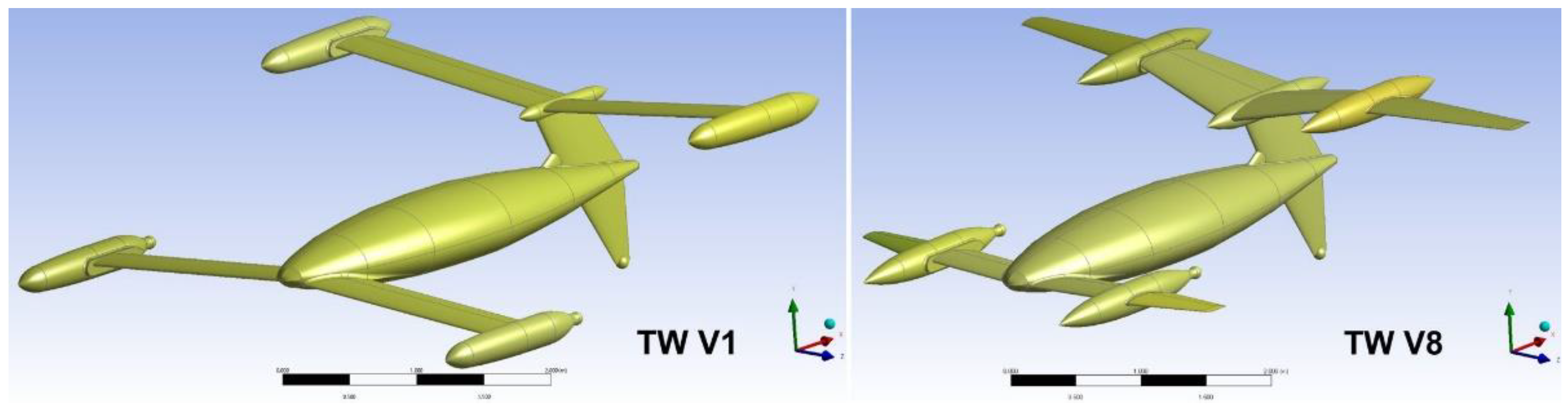
Figure 2.
Half model mesh used for the TW V8 analyses, and full model mesh, generated for the TW V14 CFD calculations.
Figure 2.
Half model mesh used for the TW V8 analyses, and full model mesh, generated for the TW V14 CFD calculations.
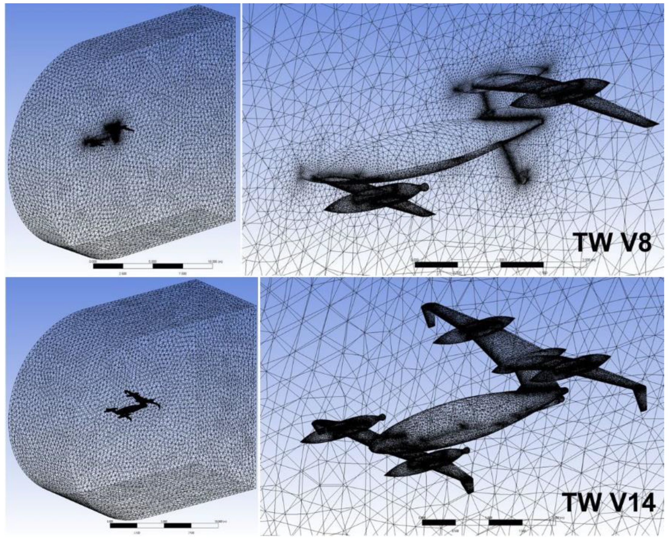
Figure 3.
One of the verification steps of the applied computational model – comparison of six aerodynamic coefficients for the same positive and negative sideslip angles.
Figure 3.
One of the verification steps of the applied computational model – comparison of six aerodynamic coefficients for the same positive and negative sideslip angles.
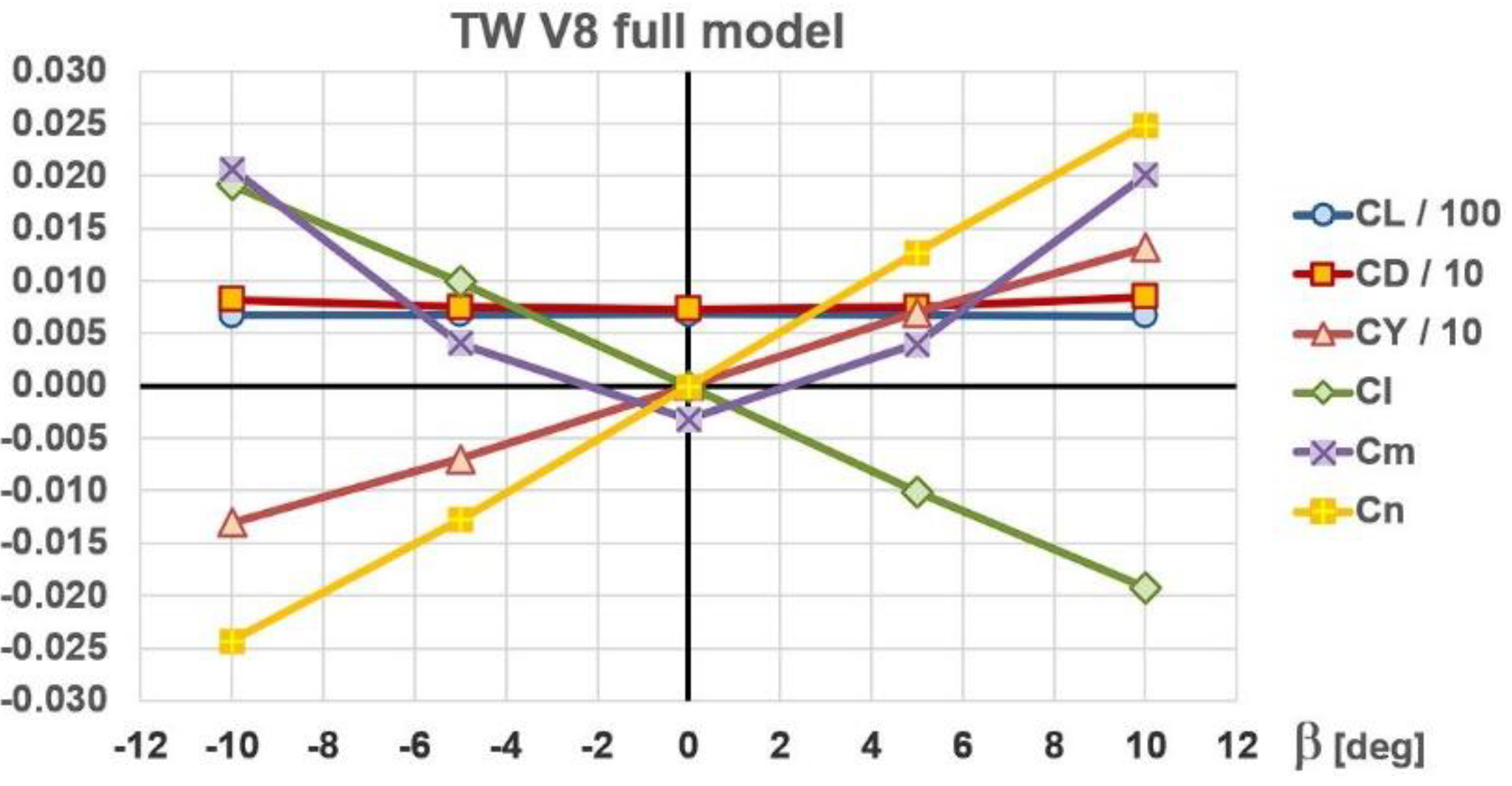
Figure 4.
Lateral-directional analyses of the TW V8: (a) roll and yaw coefficients; (b) roll and yaw derivatives and their optimum range envelopes; (c) ratios of the two derivatives for different fuselage angles of attack.
Figure 4.
Lateral-directional analyses of the TW V8: (a) roll and yaw coefficients; (b) roll and yaw derivatives and their optimum range envelopes; (c) ratios of the two derivatives for different fuselage angles of attack.
Figure 5.
Starting TW V8 configuration for lateral-directional optimizations, and the first three optimization models without winglets.
Figure 5.
Starting TW V8 configuration for lateral-directional optimizations, and the first three optimization models without winglets.
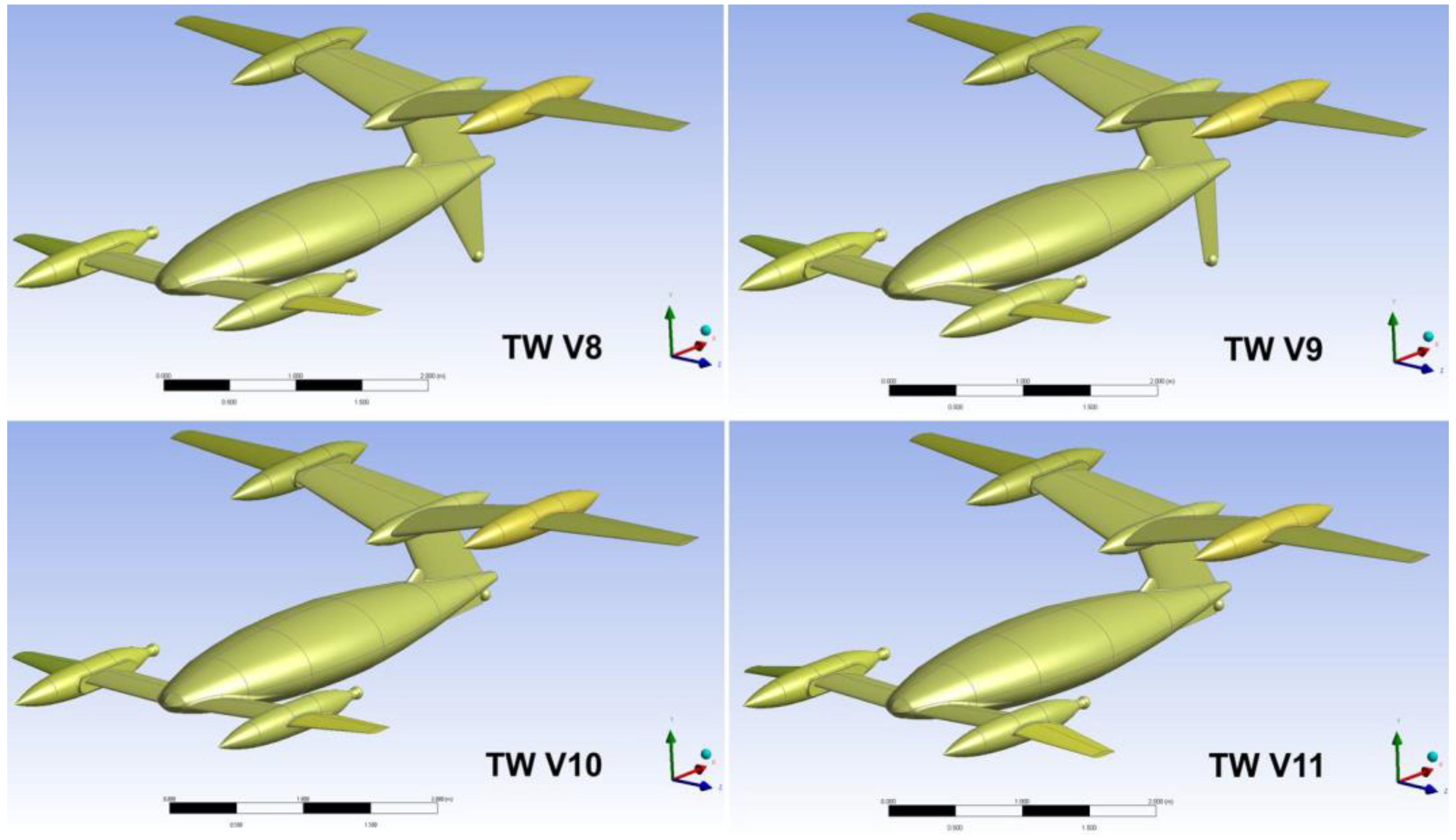
Figure 6.
Consecutive four lateral-directional optimization models with inverted winglets.
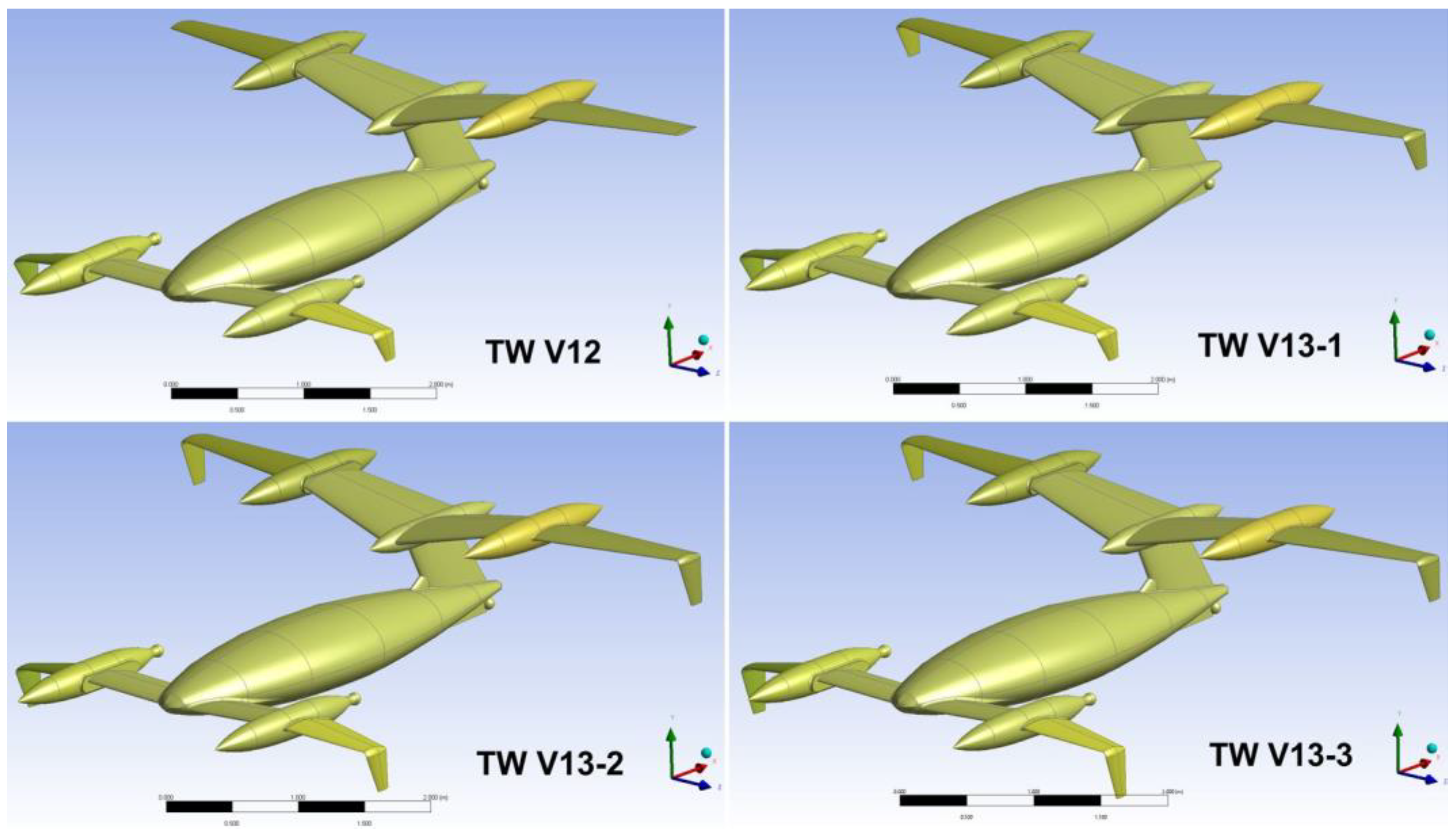
Figure 7.
Finally adopted configuration TW V14.
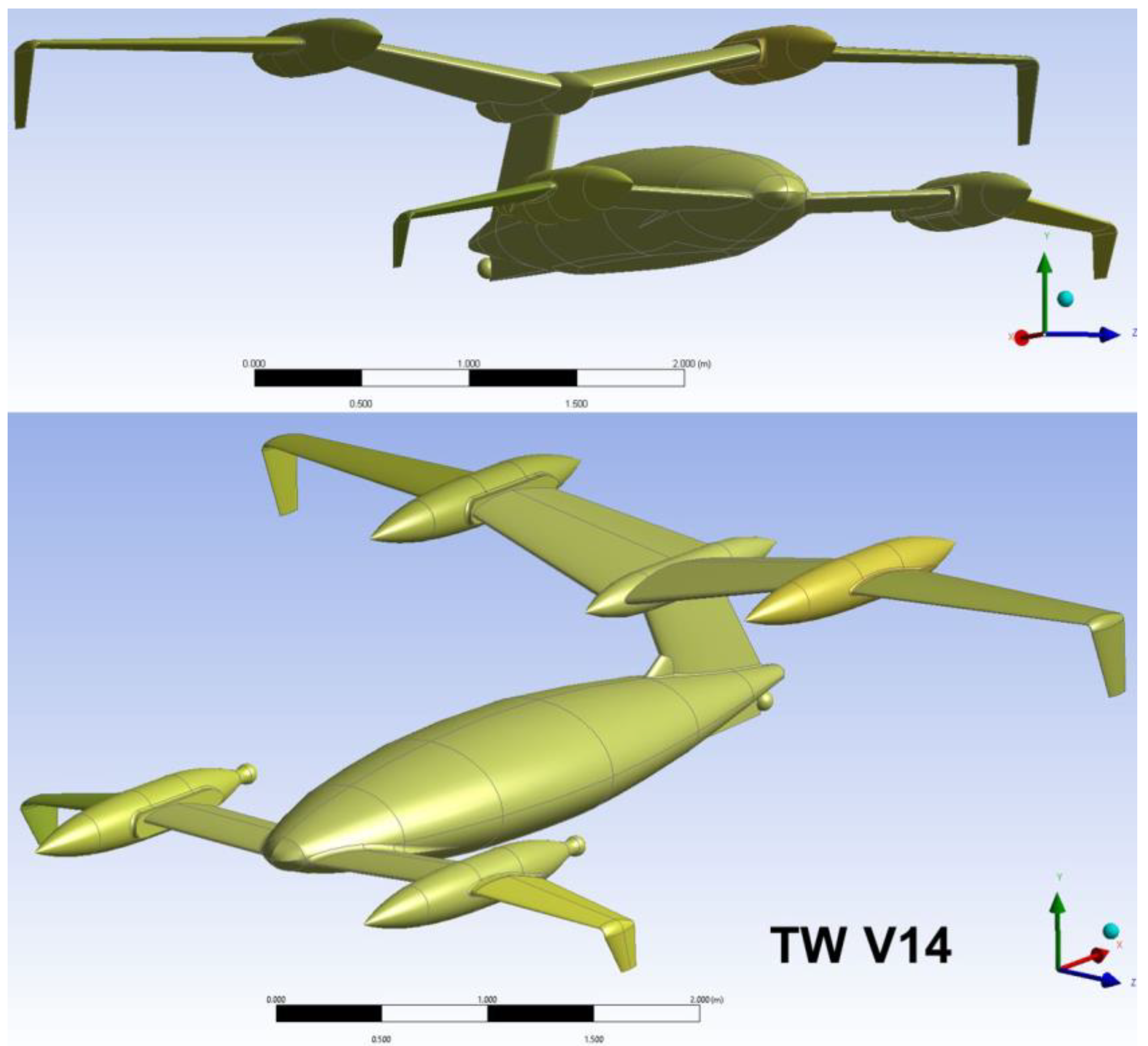
Figure 8.
Comparison of roll and yaw aerodynamic coefficients.
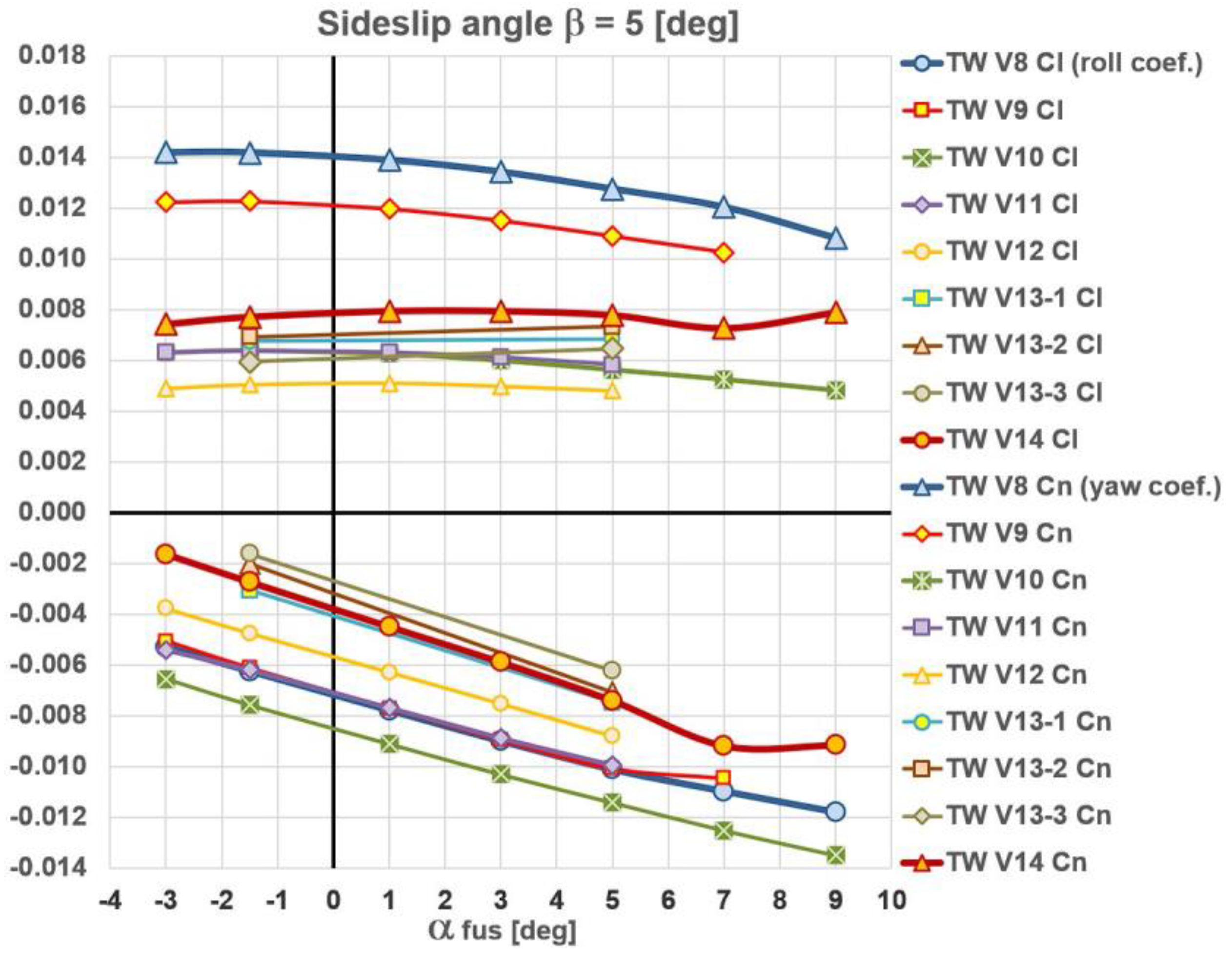
Figure 9.
Comparison of roll and yaw derivatives.
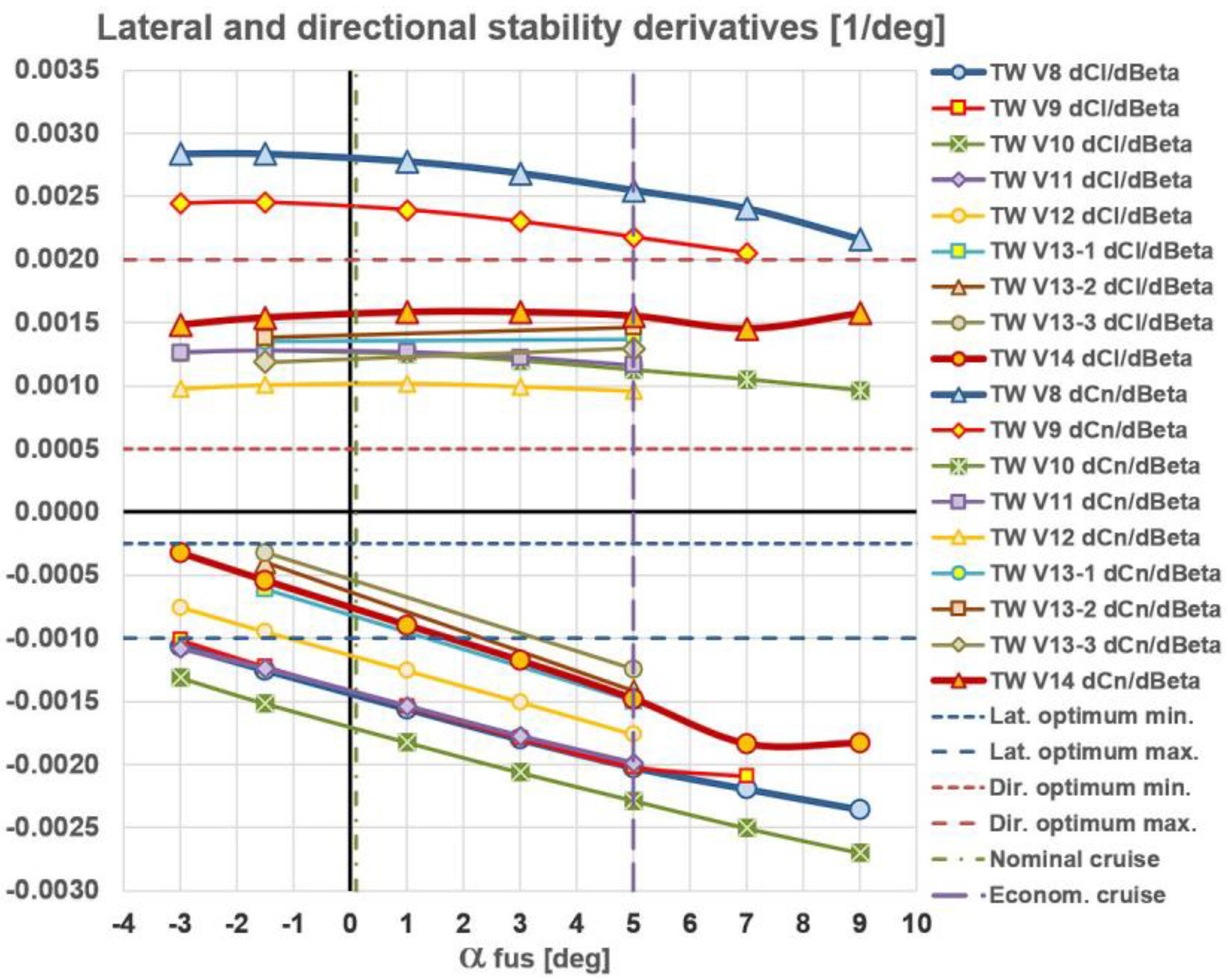
Figure 10.
Roll/yaw stability ratios.
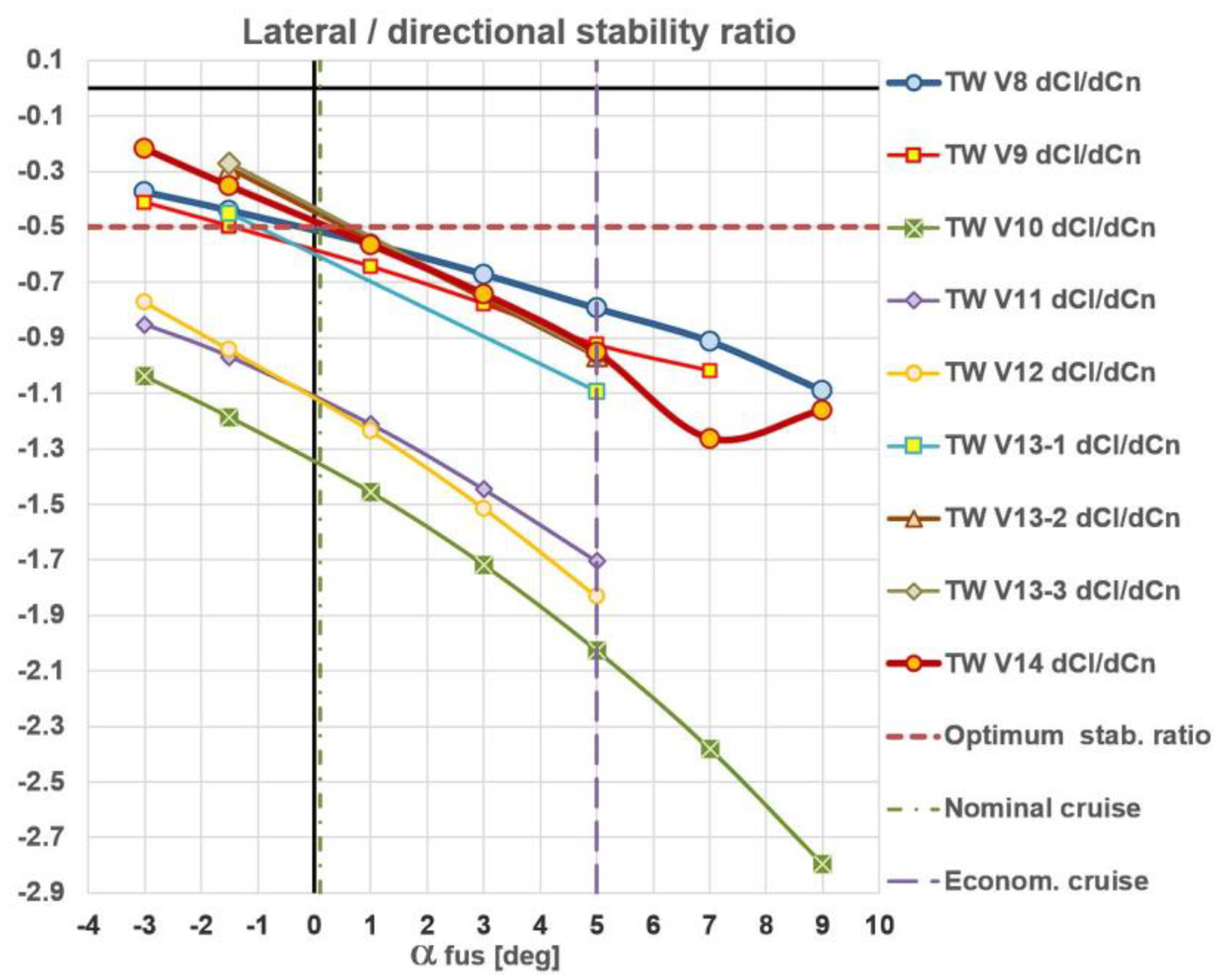
Figure 11.
Comparisons between the TW V8 and TW V14: (a) roll and yaw derivatives and their optimum range definitions; (b) ratios of the two derivatives for different fuselage angles of attack.
Figure 11.
Comparisons between the TW V8 and TW V14: (a) roll and yaw derivatives and their optimum range definitions; (b) ratios of the two derivatives for different fuselage angles of attack.
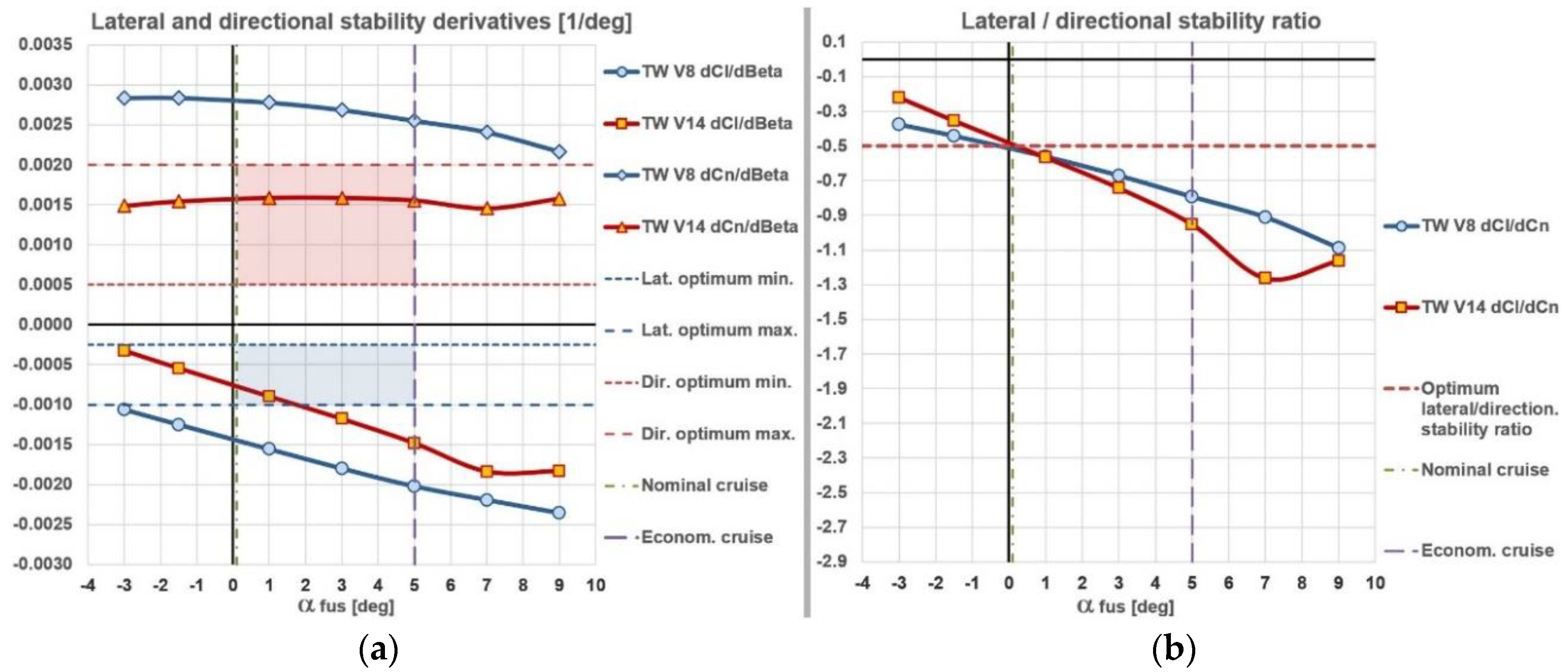
Figure 12.
Eddy viscosity distributions over and behind the two models, at the fuselage angle of attack α fus = 5° and sideslip angle β = 5°.
Figure 12.
Eddy viscosity distributions over and behind the two models, at the fuselage angle of attack α fus = 5° and sideslip angle β = 5°.
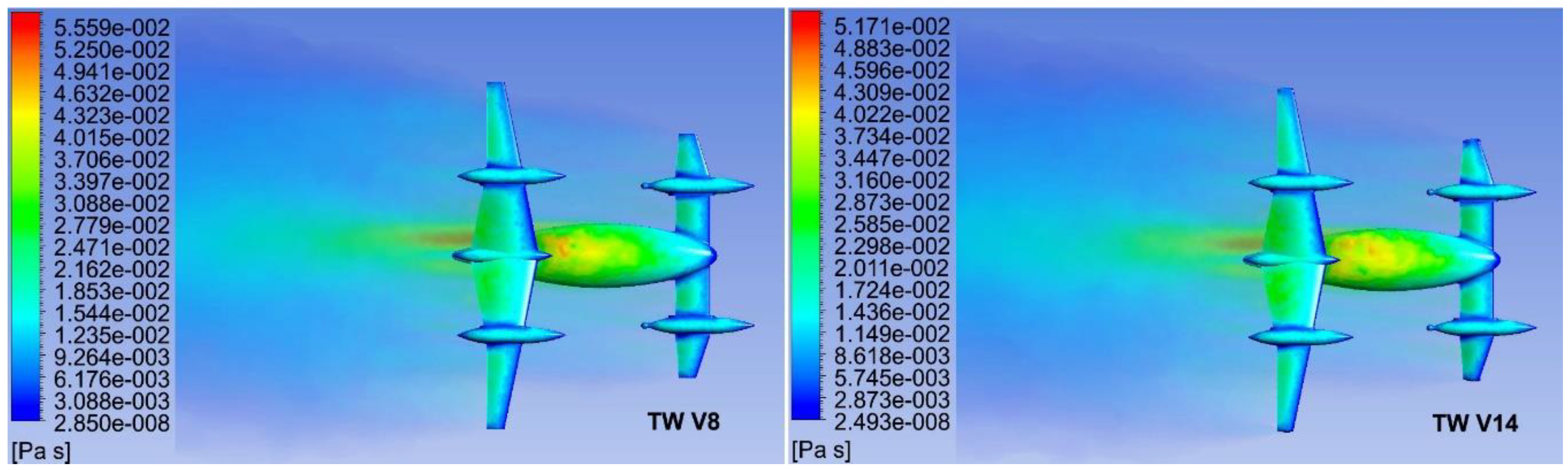
Figure 13.
Eddy viscosity distributions over and behind the two models, at the fuselage angle of attack α fus = 7° and sideslip angle β = 5°.
Figure 13.
Eddy viscosity distributions over and behind the two models, at the fuselage angle of attack α fus = 7° and sideslip angle β = 5°.
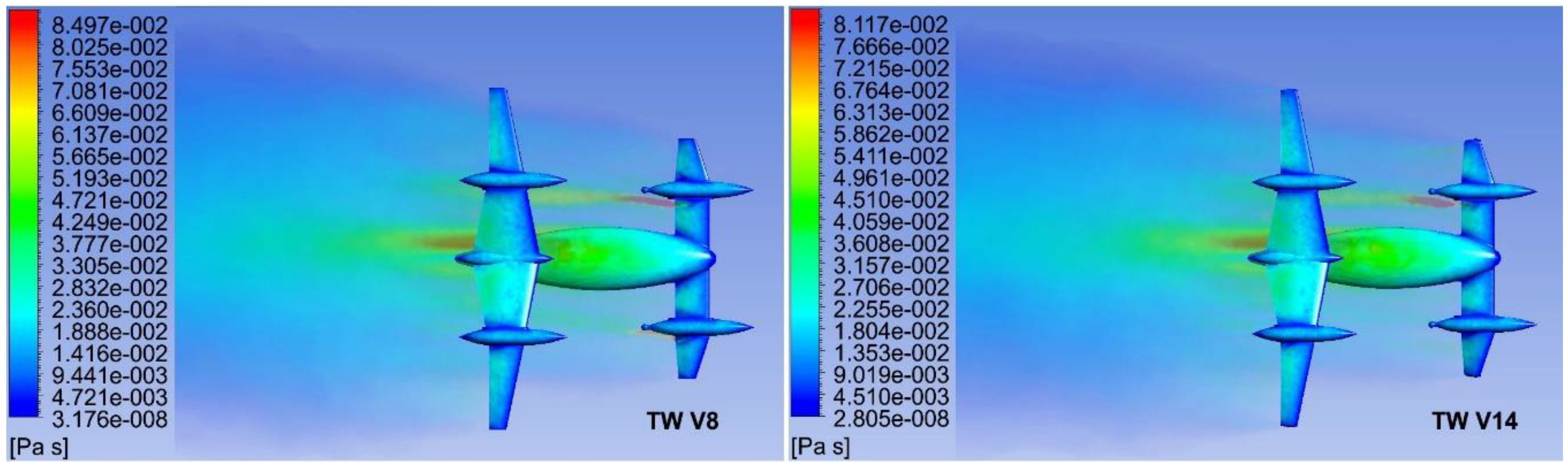
Figure 14.
Eddy viscosity distributions over and behind the two models, at the fuselage angle of attack α fus = 9° and sideslip angle β = 5°.
Figure 14.
Eddy viscosity distributions over and behind the two models, at the fuselage angle of attack α fus = 9° and sideslip angle β = 5°.
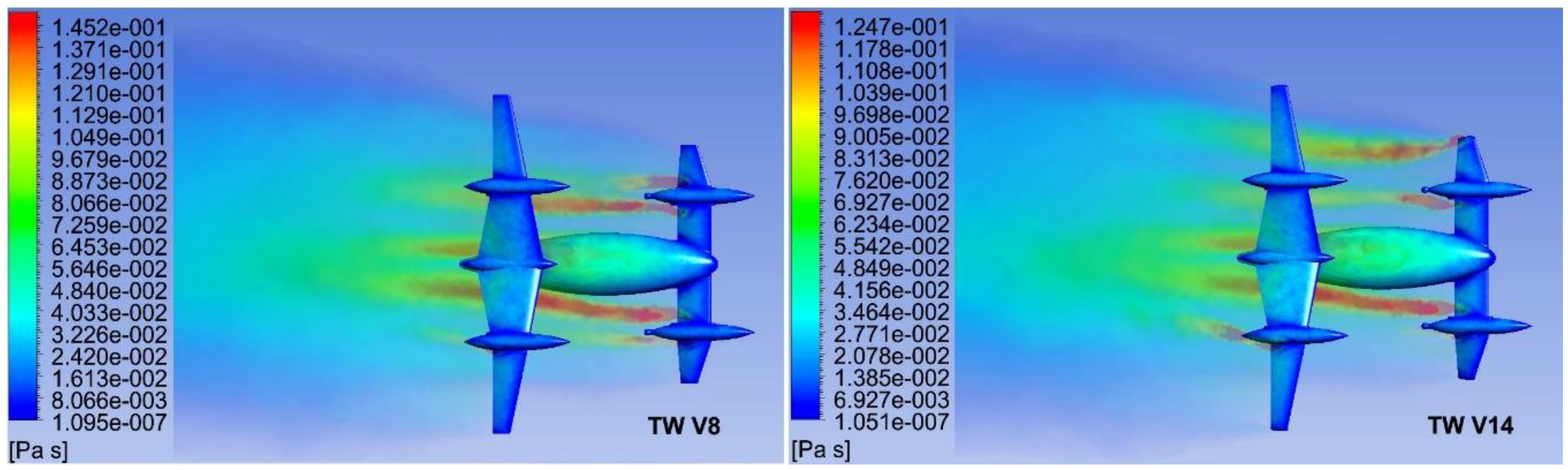
Figure 15.
Comparisons of lift, drag and moment coefficients and lift-to-drag ratios show improvements of TW V14 aerodynamic characteristics in symmetric flight conditions as well.
Figure 15.
Comparisons of lift, drag and moment coefficients and lift-to-drag ratios show improvements of TW V14 aerodynamic characteristics in symmetric flight conditions as well.
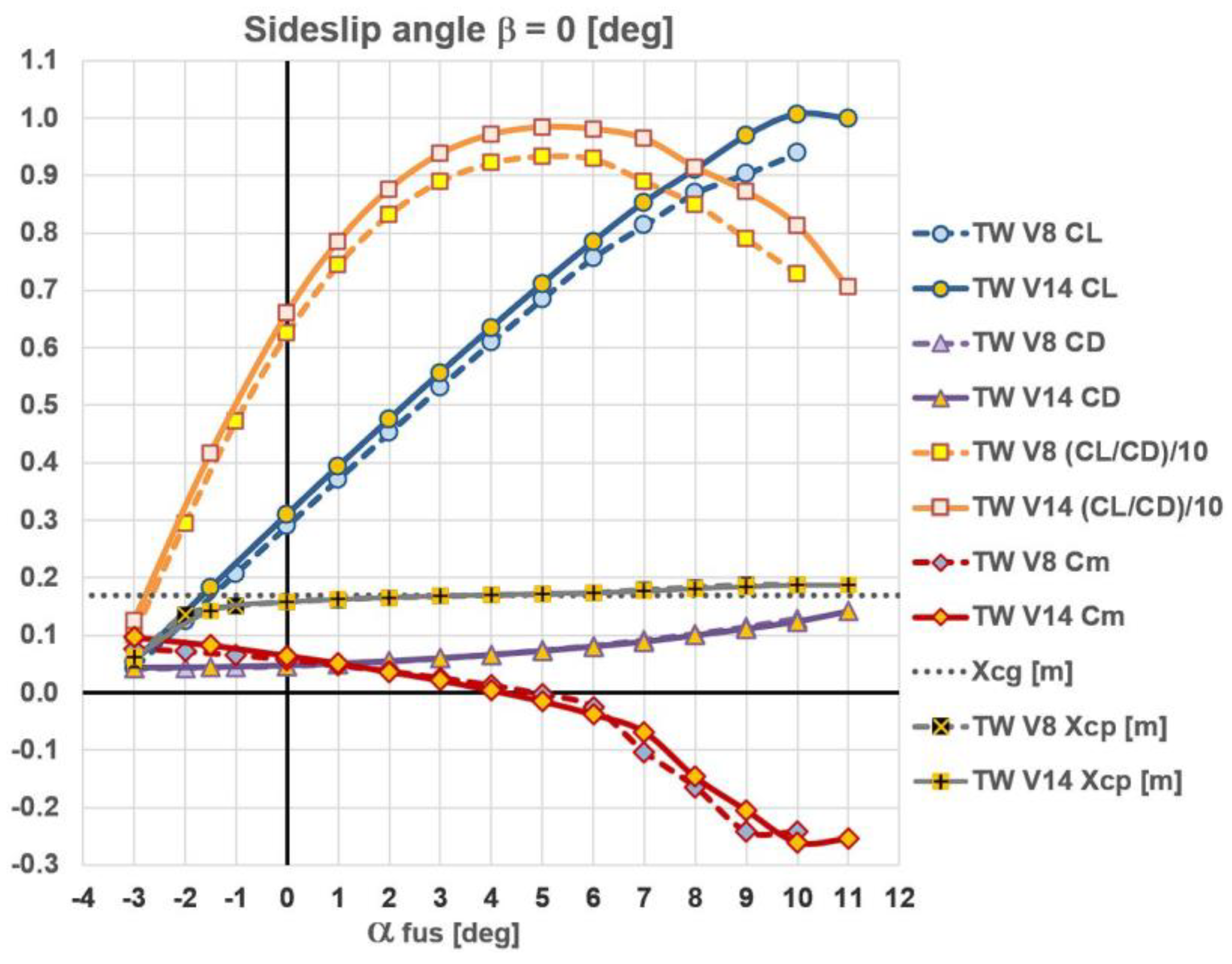
Figure 16.
On both configurations initial stall occurs on the front wing first.
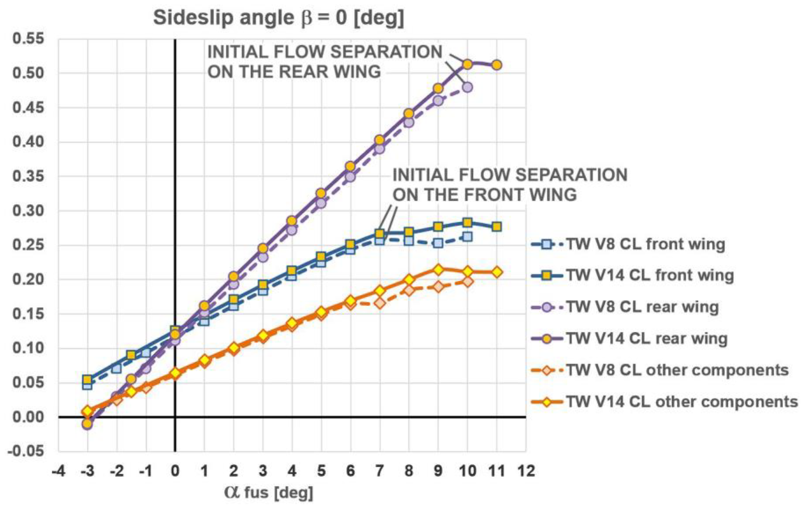
Figure 17.
The TW V8 [1] and TW V14: flow patterns represented by eddy viscosity, at the angle of attack α fus = 10° and no sideslip (isometric and side views).
Figure 17.
The TW V8 [1] and TW V14: flow patterns represented by eddy viscosity, at the angle of attack α fus = 10° and no sideslip (isometric and side views).
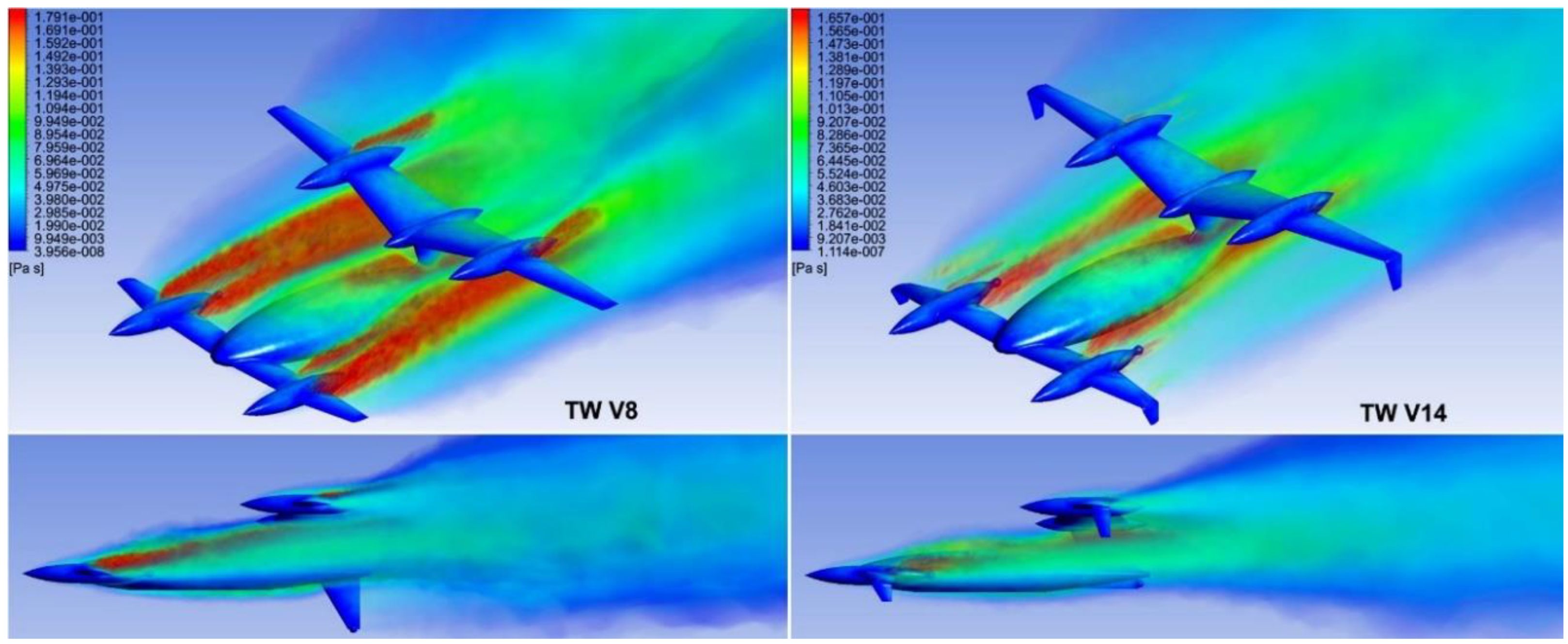

Table 1.
Comparison of the lift, drag and pitching moment coefficients obtained by half and full calculation models.
Table 1.
Comparison of the lift, drag and pitching moment coefficients obtained by half and full calculation models.
| = 5°, no sideslip | |||
| TW V8 half model | 0.685000 | 0.073379 | -0.002927 ≈ 0 |
| TW V8 full model | 0.685110 | 0.073301 | -0.003214 ≈ 0 |
| absolute difference | 0.000110 | -0.000078 | -0.000287 ≈ 0 |
| relative difference | 0.02 % | 0.11 % | / |
Table 2.
Comparison of the six aerodynamic coefficients at two (±) sideslip angles.
| = 5°, V8 full model | ||||||
| = - 10° | 0.669670 | 0.082008 | -0.130480 | 0.019168 | 0.020701 | -0.024309 |
| = - 5° | 0.681480 | 0.075054 | -0.069623 | 0.009938 | 0.004066 | -0.012785 |
| = 0° | 0.685110 | 0.073301 | -0.000053 ≈ 0 | -0.000053 ≈ 0 | -0.003214 | -0.000032 ≈ 0 |
| = + 5° | 0.681340 | 0.075000 | 0.069653 | -0.010116 | 0.004007 | 0.012745 |
| = + 10° | 0.667950 | 0.084692 | 0.131540 | -0.019195 | 0.020054 | 0.024861 |
| relative difference= ± 5° | 0.02 % | 0.07 % | 0.04 % | 1.75 % | 1.47 % | 0.31 % |
| relative difference= ± 10° | 0.26 % | 3.17 % | 0.81 % | 0.14 % | 3.23 % | 2.22 % |
Table 3.
Summary of the longitudinal aerodynamic characteristics for the V8.
| Version TW V8, no sideslip | |||||||||
|---|---|---|---|---|---|---|---|---|---|
| (°) |
(m) from nose |
(m) estimated |
front wing |
rear wing |
other components |
||||
| -3 | 0.0423 | 0.04214 | 0.0768 | 1.00 | 0.574 | 1.7 | 0.0467 | -0.0111 | 0.0067 |
| -2 | 0.1250 | 0.04254 | 0.0717 | 2.94 | 1.345 | 1.7 | 0.0702 | 0.0299 | 0.0249 |
| -1 | 0.2076 | 0.04397 | 0.0651 | 4.72 | 1.505 | 1.7 | 0.0935 | 0.0709 | 0.0432 |
| 0 (≈ FC/LL) | 0.2900 | 0.04641 | 0.0572 | 6.25 | 1.578 | 1.7 | 0.1167 | 0.1118 | 0.0616 |
| 1 | 0.3715 | 0.04989 | 0.0474 | 7.45 | 1.622 | 1.7 | 0.1394 | 0.1525 | 0.0796 |
| 2 | 0.4521 | 0.05433 | 0.0371 | 8.32 | 1.653 | 1.7 | 0.1618 | 0.1927 | 0.0976 |
| 3 | 0.5315 | 0.05974 | 0.0254 | 8.90 | 1.676 | 1.7 | 0.1836 | 0.2326 | 0.1153 |
| 4 | 0.6095 | 0.06610 | 0.0128 | 9.22 | 1.694 | 1.7 | 0.2049 | 0.2719 | 0.1326 |
| 5 (EC reg.) | 0.6850 | 0.07338 | -0.0029 | 9.34 | 1.712 | 1.7 | 0.2251 | 0.3107 | 0.1492 |
| 6 | 0.7569 | 0.08150 | -0.0253 | 9.29 | 1.732 | 1.7 | 0.2433 | 0.3491 | 0.1645 |
| 7 | 0.8133 | 0.09142 | -0.1033 | 8.90 | 1.789 | 1.7 | 0.2571 | 0.3904 | 0.1658 |
| 8 | 0.8694 | 0.10232 | -0.1649 | 8.50 | 1.828 | 1.7 | 0.2562 | 0.4283 | 0.1849 |
| 9 | 0.9026 | 0.11435 | -0.2423 | 7.89 | 1.875 | 1.7 | 0.2530 | 0.4600 | 0.1895 |
| 10 | 0.9394 | 0.12899 | -0.2422 | 7.28 | 1.870 | 1.7 | 0.2624 | 0.4793 | 0.1977 |
Table 4.
Summary of the longitudinal aerodynamic characteristics for the V14.
| Version TW V14, no sideslip | |||||||||
|---|---|---|---|---|---|---|---|---|---|
| (°) |
(m) from nose |
(m) estimated |
front wing |
rear wing |
other components |
||||
| -3 | 0.0540 | 0.04301 | 0.0961 | 1.26 | 0.613 | 1.7 | 0.0544 | -0.0095 | 0.0091 |
| -1.5 | 0.1826 | 0.04385 | 0.0823 | 4.16 | 1.424 | 1.7 | 0.0904 | 0.0552 | 0.0370 |
| 0 (≈ FC/LL) | 0.3099 | 0.04691 | 0.0640 | 6.61 | 1.574 | 1.7 | 0.1255 | 0.1196 | 0.0647 |
| 1 | 0.3935 | 0.05014 | 0.0510 | 7.85 | 1.623 | 1.7 | 0.1484 | 0.1620 | 0.0831 |
| 2 | 0.4757 | 0.05431 | 0.0362 | 8.76 | 1.658 | 1.7 | 0.1707 | 0.2039 | 0.1012 |
| 3 | 0.5566 | 0.05939 | 0.0213 | 9.37 | 1.683 | 1.7 | 0.1924 | 0.2450 | 0.1192 |
| 4 | 0.6352 | 0.06541 | 0.0038 | 9.71 | 1.705 | 1.7 | 0.2131 | 0.2855 | 0.1365 |
| 5 (EC reg.) | 0.7114 | 0.07230 | -0.0150 | 9.84 | 1.724 | 1.7 | 0.2328 | 0.3252 | 0.1534 |
| 6 | 0.7848 | 0.08002 | -0.0380 | 9.81 | 1.742 | 1.7 | 0.2511 | 0.3643 | 0.1694 |
| 7 | 0.8533 | 0.08850 | -0.0681 | 9.64 | 1.764 | 1.7 | 0.2667 | 0.4026 | 0.1840 |
| 8 | 0.9101 | 0.09954 | -0.1464 | 9.14 | 1.814 | 1.7 | 0.2687 | 0.4412 | 0.2001 |
| 9 | 0.9690 | 0.11110 | -0.2043 | 8.72 | 1.846 | 1.7 | 0.2764 | 0.4780 | 0.2146 |
| 10 | 1.0069 | 0.12382 | -0.2602 | 8.13 | 1.874 | 1.7 | 0.2825 | 0.5129 | 0.2115 |
| 11 | 0.9993 | 0.14172 | -0.2543 | 7.05 | 1.871 | 1.7 | 0.2764 | 0.5121 | 0.2109 |
Disclaimer/Publisher’s Note: The statements, opinions and data contained in all publications are solely those of the individual author(s) and contributor(s) and not of MDPI and/or the editor(s). MDPI and/or the editor(s) disclaim responsibility for any injury to people or property resulting from any ideas, methods, instructions or products referred to in the content. |
© 2024 by the authors. Licensee MDPI, Basel, Switzerland. This article is an open access article distributed under the terms and conditions of the Creative Commons Attribution (CC BY) license (http://creativecommons.org/licenses/by/4.0/).
Copyright: This open access article is published under a Creative Commons CC BY 4.0 license, which permit the free download, distribution, and reuse, provided that the author and preprint are cited in any reuse.


