Submitted:
18 January 2024
Posted:
19 January 2024
You are already at the latest version
Abstract
In northern Canada where permafrost is prevalent, a shortage of accessible, affordable, and high-quality housing has been ongoing for decades. Design of foundations in permafrost presents unique engineering challenges due to permafrost soil mechanics and climate change. There is no specific design code for pile or shallow foundations in northern Canada. Consequently, the design process heavily relies on the expertise and experience of Arctic geotechnical engineers who have specialized knowledge in this field. Therefore, a comprehensive review of the practice or literature in foundation design in the Arctic would be necessary. The main objective of this review paper is to provide an overview of the common foundations in permafrost and the techniques adopted to counteract the effects of frozen soils. This study conducted a literature review of state-of-the-art practices on deep and shallow foundations used in northern Canada, including common steel pipe piles and thermosyphons. The review summarized the current principles, including adfreeze strength, creep settlement, and frost heave, used in the foundation design in permafrost. Then this paper summarized the findings from interviewing several engineers or professionals who have experiences in the design of foundations in permafrost. The interviews revealed the technical and non-technical aspects of foundation design practice in northern Canada. Lastly, in order to demonstrate the design methods, the paper presented two examples where screw piles and steel pipe piles were designed to support a residential building in northern Canada, according to the state-of-practice criteria for adfreeze strength, long term settlement and frost heave.
Keywords:
frozen soil
; foundations in permafrost
; pile design
; screw piles
; climate change
1. Introduction
About half of Canada's land is located in permafrost regions, extending across the Northwest Territories, Yukon, Nunavut, and the northern regions of most provinces. The growth and expansion of communities in the Arctic are increasing due to factors such as population growth and the need to utilize natural and mineral resources. This rise in activity requires new infrastructure and facilities, presenting new engineering challenges as unique problems arise when working with frozen soils [1].
Constructing on permafrost presents challenges, especially in foundation work, due to the unique properties of frozen soil. One of the challenges in dealing with permafrost is addressing old buildings that were constructed using inadequate methods and designing new constructions to mitigate the effects of climate change, while also aiming to reduce building costs [2]. There is no design code for foundations in permafrost in Canada, and so the design of deep or shallow foundations largely relies on the experiences of professional engineers or contractors.
A literature search suggests that there is no review on the practice of deep or shallow foundations in permafrost regions, particularly in northern Canada. The objectives of this review paper are to provide a comprehensive summary of the state-of-practice of foundations engineering in the permafrost regions of northern Canada. The present paper will review the currently common foundation types and their pros and cons. Interviews were carried out with engineers and professionals residing in northern Canada or possessing expertise in designing foundations in permafrost. This paper compiles insights from these interviews to guide the practice of foundation design in northern Canada. Finally, a screw pile and steel pipe pile were designed and compared in accordance with state-of-practice criteria for adfreeze strength, long-term settlement, and frost heave.
This review paper targets arctic geotechnical engineers, civil engineers, construction professionals, or properties owners. It is anticipated to assist potential readers with a facilitated guide to foundation design principles.
2. Foundation Engineering in the Permafrost Regions of Northern Canada
Permafrost covers about 20 % of the world's land area. When the soil temperature increases to 0 °C, the resistance of the soil decreases significantly due to the increase in unfrozen water and decrease in adfreeze bond strength. Therefore, maintaining the lowest soil temperature possible is vital for foundations in frozen soils. Unfortunately, global warming is increasing the soil temperature in permafrost, which is causing a significant loss of soil bearing capacity, shear strength, and increasing frost heave forces on foundations, posing a problem for both old and new buildings.
Zhang et al. [3] conducted a simulation to assess the dynamic changes in ground thermal regimes and permafrost conditions in Canada from 1850 to 2100. The simulation involved the use of software tools and included a comparison of six different climate change ground conditions (i.e. scenarios), considering depths up to 120 meters at a specific site located at 60 °N, 105 °W. Table 1 presents predictions for three of these scenarios, focusing on depths up to 40 meters. The results demonstrate that ground temperature variations can reach up to 7 °C at the surface and over 2 °C at a depth of 40 meters. The author also explained that this tends to increase the thickness of the active layer and induce permafrost thaw.
A study conducted in Russia territory by Streletskiy et al. [4] showed that climate change has led to an increase in the active layer and a decrease in the bearing capacity of foundations, potentially damaging over 50% of residential buildings, as well as approximately 20 % of commercial and industrial structures by significant permafrost degradation by the middle of the 21st century. The estimated cost of this damage is more than $80 billion, imposing a significant economic burden on the nation.
The first constructions in northern Canada were limited to small buildings supported on pads or footing only in areas with shallow deep permafrost due to the frost action. Therefore, the expansion of the community and industrial development, resulted in the need for new construction methods to support higher loads and frost action forces [5]. Since the 1950’s the use of piles has been growing because they can be long enough to have an adequate embedment providing a stable foundation, capable of resisting forces and displacements related to frost heaving [6]. The constant pursuit of cost-effective solutions in permafrost regions has led to an expansion in the variety of foundation options, not only in deep foundations but also in shallow foundations. Furthermore, techniques to lower the soil temperature are being implemented, such as the application of thermosyphons in the foundations.
The purpose of this section is to provide a comprehensive overview of the practice of foundation engineering in northern Canada. The objective is to examine the prevalent and promising methods, emphasizing their distinctive characteristics, advantages, and disadvantages.
2.1. Existing Guides to Foundation Practice in Canadian Permafrost
Despite the absence of a specific design code for foundations in Canadian permafrost, manuals are available to assist engineers and builders. In Canada, geotechnical engineers frequently refer to the Canadian Foundation Engineering Manual (CFEM) regarding the design of foundations underpinning commercial or residential structures. CFEM 2023 [7], the latest version the manual, outlines the permafrost investigation techniques and general design considerations of foundations for building structures.
Canadian Standards Association (CSA Group) has published some manuals related to permafrost and foundations. One of them addresses moderating the effects of permafrost degradation on existing building foundations [8]. This manual discusses the factors that cause permafrost degradation, outlines techniques to mitigate these effects, and provides insights into frozen soil properties and various foundation types.
CSA PLUS 4011.1 [9], which is a design and construction report, offers detailed technical information, considering various foundation systems, ground conditions, and different scenarios in permafrost. The guide includes a review of the distribution and climate conditions of permafrost in Canada. Additionally, the report correlates how climate and soil conditions impact foundations in permafrost, providing insights into the relationship between environmental factors and foundation performance in these regions.
In 2017, the National Standard of Canada published guidance on specified minimum requirements for geotechnical investigations for buildings in permafrost [10]. Furthermore, the Government of the Northwest Territories published a manual of building practice for northern facilities [11]; this publication serves as a technical reference and design guide to assist building developers in frozen soils, addressing not only foundations but also encompassing all stages of building construction.
The literature provided valuable guidance on foundations in permafrost and detailing considerations for various situations. However, none of them provide a practical method to follow and design in permafrost. Consequently, engineers may interpret and design foundations in different ways based on their knowledge and expertise.
2.2. Thermosyphon Method
Thermosyphon and insulation are a common method used to maintain a low-temperature permafrost temperature, against the hot seasons of the year and climate change. Lower temperature avoids the frost action effect and prevents the loss of the soil's adfreeze bond capacity due to its increased temperature.
Additionally, the presence of insulation may help prevent heat transfer from the soil surface to the permafrost layer. This can be accomplished using materials such as foam, fiberglass, or other insulating materials that have a low thermal conductivity. The insulation material is typically placed between the soil surface and the structure to be protected, effectively reducing the amount of heat that reaches the permafrost layer.
The thermosyphon method uses the natural circulation of a fluid, such as water or a refrigerant, to transfer heat from the warm soil surface to a colder depth. The heat transfer occurs as the fluid rises to the surface and releases heat, and then sinks back to the deeper, colder layer where it picks up more heat. This cycle continues until the temperature at the surface reaches a state of thermal equilibrium with the surrounding environment. This method can be applied to all types of foundations in the Canadian Arctic.
Thermopile is a method in permafrost regions that combines the features of both a thermosyphon and an adfreeze pile. Thermopiles can be applied using either steel pipe piles or screw piles. These structures serve to transfer heat from the ground to the atmosphere, helping to maintain low soil temperatures and preserve the adfreeze bond capacity of the soil. The thermopile consists of two primary components: an evaporator section located in the ground and a radiator section located above the ground. The evaporator section absorbs heat from the surrounding soil, while the radiator section dissipates this heat into the air (Figure 1). This passive transfer of heat helps to increase the soil strength and reduce the rate of pile creep, making the thermopile an effective solution for foundation design in permafrost regions [12].
Another way to use thermosyphons to cool the soil is in the form of a flat loop. Unlike traditional thermopiles, which only cool the circumferential area around the pile foundation, flat loop thermosyphons aim to maintain the entire perimeter of the building. This design involves creating a large, flat loop of pipes buried within the permafrost layer, which continuously circulates a refrigerant to transfer heat away from the surrounding soil and keep the permafrost layer cool (Figure 2). This method may be particularly effective for large structures, such as factory buildings, where maintaining a consistent temperature throughout the entire perimeter is important for preserving the stability of the structure.
2.3. Spread Footings
Shallow foundations, such as footings, are also used in permafrost regions due to their relatively simple design and low cost. However, several challenges need to be considered when designing and constructing footings in permafrost. The freezing and thawing of soil can cause significant movement and instability, making it difficult to predict the behavior of the foundation. As a result, footing is generally designed to support smaller loads and is usually not suitable for larger structures or heavy loads. Additionally, the depth of the active layer, which is the layer of soil that thaws and refreezes each year, can vary greatly, and if it is too deep, it can become impractical to use footings as they must reach the permafrost layer to provide adequate support [14].
To address these challenges, several techniques have been developed to improve the performance of footings in permafrost. For example, it is essential to minimize the disturbance of the soil during excavation and construction and to allow the soil to freeze back as quickly as possible after construction. One possibility is excavating and building the foundation in the fall when the soil is already starting to freeze, or by using techniques such as insulation and thermal barriers to reduce heat loss from the structure [15].
Another important consideration is the material used to backfill the foundation. Gravel or sandy soil is typically used, as it is less prone to freezing and thawing than other types of soil. Additionally, a crawl space is often incorporated below the floor to allow for ventilation and dissipation of heat, and the columns and footing should be protected with a low-adhesion coating to prevent adfreeze uplift forces.
Figure 3 shows an example of a possible footing foundation with techniques to mitigate the effects of permafrost. The footing is placed as deep as possible into the permafrost. The natural soil below and surrounding the foundation should be replaced with non-frost-susceptible fill to reduce frost heave. A polyethylene sleeve is added to reduce the uplift force caused by frost heave. Insulation is added on top of the soil, and a crawl space is included to reduce the temperature of the soil and prevent thawing.
Backfilling the footing with non-frost susceptible soils (NFS) may not be sufficient to combat the freeze-thaw effect, as the surrounding soils will still be affected by this process. One option is to replace all the active layer soil with NFS soil and embed the footing in the permafrost or ground. However, more often, a layer of NFS soil is added on top of the original soil, causing the permafrost layer to rise. The use of insulation, ventilation ducts, crawl spaces, and thermosyphons should be considered to decrease the temperature of the soil and increase its stability.
Figure 4(a) depicts a schematic example of a footing embedded in permafrost and insulated by a gravel pad on the ground surface. In this example, it is observed the elevation of the permafrost layer to a new layer between the insulation and the footing. This can be explained by the addition of a thick layer of NFS, crawl space, and insulation, which protect the lower layers to remain at temperatures below 0 °C throughout the year. Figure 4(b) shows an application example for this footing design. In this case, a building in Inuvik was constructed with spread footings covered by a layer of gravel and equipped with ventilation ducts. It is possible that insulation was also placed on top of the footing to ensure thermal stability.
For shallow foundations, whether it involves insulation, ducts, or thermosyphons, periodic evaluation is necessary to ensure that all mechanisms are functioning as designed. Malfunctioning of any component or unforeseen temperature rise can be sufficient to damage the entire structure. For example, a hospital facility, that was built in 2004 in northern Canada with concrete footings, faced problems with several pipe loops of the thermosyphons, reducing the cooling capacity of the system and affecting the foundation's freeze-back. This issue affected the walls and floors above and even jammed an emergency exit [18]. Therefore, the application of thermosyphons alone does not solve all problems, and periodic monitoring of temperature and refrigeration equipment is still necessary.
2.4. Wood Blocking Method
The wood blocking method is a technique used to remediate building foundations that have been damaged by frost action. This method involves replacing the original foundation, usually timber piles, with a wooden blocking system to prevent further frost damage. One of the main advantages of the wood blocking method is its cost-effectiveness compared to other remediation techniques. The method utilizes locally sourced wood and does not require heavy equipment, making it a viable option for buildings in remote areas. Additionally, the wood blocking method is more sustainable than other techniques, such as concrete or steel piles for foundations. The blocking system can be customized to fit the specific needs of the building and the surrounding environment. This adaptability makes the wood blocking method a versatile option for remediating buildings on different types of soil, even if the ground is uneven or if there is a high crawl space.
In a recent study by Liu et al. [19], the wood blocking method was evaluated for its performance in remediating a building in the Canadian Arctic (Figure 5). The study monitored the temperature, moisture content, and movement of the building over two years.
Liu et al. [19] showed that the wood blocking method can be effective in preventing lateral movements of a building. However, a small subsidence was detected due to seasonal weather, which resulted in a gap of up to 7 mm in some blocks over 2 years (Figure 6). The positive aspect is that the wood blocking and the structure are connected by wood wedges that can be easily readjusted after seasonal movement. Therefore, the wood blocking method can be a cost-effective and efficient solution for repairing damages caused by the freeze-thaw effect in the Canadian Arctic and other cold climates. The use of locally sourced materials and adaptability make it a sustainable and flexible option for remote areas with limited resources.
2.5. Jack Pads
Screw jacks are an economical foundation method in permafrost. To install them, one simply needs to select the number of supports required to sustain the foundation and install them directly into the soil, without considering the active layer or soil temperature. It is recommended to level the ground and replace the surface layer with NFS soil. Additionally, a wooden or metal sheet must be placed beneath the screw jack to increase the contact surface area between the load transmitted by the jack and the soil Figure 7. However, each support behaves differently due to the frost and thawing cycles, which can cause differential settlement in the building resulting in cracking and structural damage.
Periodic adjustment of the jacks may be necessary to prevent damage to the structure. Generally, screw jacks are used for light loads, making them a popular choice for residential buildings. However, they may not be suitable for larger or heavier structures, as the load capacity of each jack is limited. Additionally, the installation process can be time-consuming and require a significant amount of labor. As with any foundation type, proper design and installation are crucial to ensure the safety and stability of the structure. This technique is also important for foundation repairs or if an extra crawl space is needed. [20].
2.6. Space Frame System
A new technique of shallow foundations known as the space frame system has been developed to overcome the challenges posed by frost heave. This system is composed of interconnected steel or aluminum members that form a framework or grid structure that supports the building or structure (Figure 8). The space frame system is designed to distribute the load of the structure across a larger area, reducing the pressure on individual points and providing a more stable foundation. The space frame system ignores the soil conditions and is placed directly on top of the ground [21].
One of the advantages of the space frame system is its efficient use of space, as it eliminates the need for excavation of large amounts of soil or the use of heavy equipment. Also, a sand or gravel pad is not necessary. Simply clear and level the area to facilitate the construction of the foundation frame, avoiding the high costs associated with soil excavation or the application of piles, and the equipment required to access permafrost areas. Additionally, this system is versatile and can be used for a wide range of building types, such as commercial buildings, industrial buildings, and residential buildings [22].
Space frame system can adjust the frame according to the displacement of the structure, which is important when working in frozen soils. The system is designed to accommodate movement by using flexible connections and joints between the members of the frame (Figure 9). These flexible connections and joints allow the structure to move and shift without causing damage to the system, making it a suitable solution for foundations in permafrost areas [21].
Space Frame system can adapt its frame to align with the structure's displacement, which is an important consideration when dealing with frozen soils. The system's design incorporates features that allow for movement by utilizing flexible connections and joints among the frame members (Figure 8). These flexible connections and joints not only enable the installation of the foundation on uneven ground but also facilitate adjustments after any displacement caused by frost heave [21]. Even if the pads lose contact with the soil and their connections are not adjusted, the load distribution among the multiple pads in direct contact with the ground remains effective. This is because the foundation frame's ability to bridge soft spots and function as a rigid slab under frost heave and thaw conditions helps preserve the structural integrity of the building (Figure 9b).
2.7. Timber Piles
The first use of piles in the Canadian Arctic was timber piles because of their availability. Their length is usually between 6 and 15 m and diameters from 150 to 250 mm. An advantage of the timber pile is its rough surface, increasing its shear strength capacity. Additionally, it possesses better insulation properties than steel piles, important for hindering the flow of warmer temperatures from the surface to the soil. Moreover, in some remote locations, heavy shipments may be inaccessible for part or all of the year, making the application of other foundation types or technologies challenging. This difficulty in transportation and accessibility makes timber a practical choice as it is readily available in the natural environment and helps save on transportation costs.
However, a concern is related to the contact of the timber with the active layer, where there is the melting and freezing of the ice. When the ice melts, water penetrates the wood causing it to swell. During the winter, the wood will dry, shrinking. This cycle of swelling and shrinking will cause cracks and after repeated episodes of swelling and shrinking these cracks will grow, damaging and compromising the performance of the pile.
Protecting the timber from water is a common attempt to keep the integrity of the pile, for example, using tuck tape around the pile from the ground until the depth of the permafrost table (Figure 10). However, the temperature of the soil may change for some reason, like global warming or soil disturbance, increasing the depth of the active layer, and creating a gap for water infiltration. Since is not easy and accurate to predict the changing temperature and is not possible to cover the whole pile with tuck tape otherwise it will lose the adfreeze bond capacity.
2.8. Steel Pipe Piles
Steel piles have been a viable solution to replace timber piles in the Canadian Arctic during the last decades. Usually, steel piles have less roughness than timber piles, however, the capacity to build larger steel piles helps reach deeper bedrocks which can provide a higher adfreeze strength.
Steel piles can be driven or backfilled. The first ones are usually H-piles, they can be installed two or three times faster than the backfill type and it causes less physical and thermal disturbance in the soil. Thus, driven piles can be loaded sooner than other ones. However, the strength of permafrost will rarely allow to use of driving equipment, such as a vibratory hammer, and will likely cause the pile to be crushed [23,24].
The backfill pile is constructed by inserting a freeze pipe into a drilled hole that is larger than the pile diameter. Normally, the result will be an annular void between the pipe and the soil (Figure 11). This void can be filled with sand and water or can be grouted with cement. This process can cause a huge physical and thermal disturbance in the soil. The drilling process and the vibration of the backfill to remove void spaces can disturb the soil, causing settlements and warming the soil. Besides, the backfill temperature should be over the freezing, and in the case of grouting, the temperature remains higher due to the cement curing. All these processes contribute to warming the soil surrounding the pile, leading to a reduction in the shear strength capacity of the pile and potential settlement. To apply a load effectively, the soil temperature needs to return to its original state, freezing back and thereby restoring the strength and stability of the foundation. During the winter, the heat dissipates faster, so the freezeback time is shorter, and during the summer the freezeback time will depend on the cold reserve of the permafrost below the thawed active layer.
Artificial freezeback has been used for a long time to restore the ground temperature and, thereby, restore the frozen soil properties. Thermopile is one of the oldest examples of the application of artificial freezeback in the soil. It can be used with glycol lines that freeze the backfill during the construction, but not after that, or using thermosyphons that keep working continually after the construction removing heat from the ground [25,26].
The first time that thermopiles were used to stabilize pile foundations was in 1960 at the Aurora and Glennallen communications sites in Alaska (Figure 12). This technique has since become a widely accepted method for foundation stabilization in permafrost regions. Initially, propane was the refrigerant of choice, but it was later replaced by carbon dioxide due to safety concerns. This approach reduced the frozen temperature in lower layers and even increased the permafrost layer, potentially enhancing the adfreeze strength between the soil and foundation and improving the load capacity of the foundation.
2.9. Screw Piles
Helical piles, or screw piles, consist of a helically shaped bearing plate or multiple plates attached to a central shaft [7]. In frozen soils, they are made of steel and can be installed by applying torque. However, when the frozen soil is too cold, installation through torque may not be possible as the soil may be too strong, potentially damaging the pile during penetration. In such cases, predrilling a hole and using a non-frost susceptible backfill may be necessary for installation. Screw piles have been widely used in permafrost because they can have various helix and shaft diameters and embedment depths, can be quickly installed, are removable, and can be reused [28].
The presence of helices or threads in the piles increases the strength of the pile-soil system and has a great advantage in mitigating frost-jacking forces caused by the freezing soil in the active layer. Figure 13 shows an uplift bearing resistance being formed by the cylindrical shear resistance along the bottom and top of the, this increase of strength helps against the heaving forces threads. The helices must be placed below the active layer and the use of their use does not eliminate the need for other methods of combating frost heave forces. Instead, the use of screw thermopiles is also recommended to counter soil heating and reduce the effects of frost heave.
The foundation used for a commercial building in Inuvik was screw piles with thermosyphons, and the design life of the building is 50 years (Figure 14). The project contained 3 meters of unfrozen zone, and the foundation would not be able to reach bedrock. A series of procedures were made to ensure soil stability. Firstly, the native soil was excavated and dewatered, then replaced with NFS soil, and slab insulation was added below the building. The use of thermo screw piles was important for the design to increase the interaction between the foundation and soil and to maintain the soil temperature as low as possible. This can be noted by the fact that the author justifies the reduction of the factor of safety to 1.0 in the design for frost heave [12].
3. Findings from Interviewing Arctic Foundations Professionals
This section aims to provide a practical insight into foundation engineering and business in the Canadian Arctic. The discussion is based on interviews with engineers and companies that have experience in the region. Six participants were interviewed by the authors and are referred to as interview guests IG1 to IG6. The guests included three Arctic geotechnical/civil engineers, one architect/developer, and one Arctic community leader. The guests live in Edmonton (AB, Canada), Yellowknife (NWT, Canada), Inuvik (NWT), and Cambridge Bay (Nunavut, Canada).
3.1. Interview questions and response
Major questions and their response are provided herein.
- What is the major concern regarding foundations in permafrost?
IG1, IG3, and IG4 commented that a major concern in permafrost is the effects caused by frost heave, which can cause differential movements in the structure, so all possible methods should be used to reduce this effect. IG1 and IG2 emphasized the importance of keeping the permafrost temperature as cold as possible because the adfreeze strength of the foundation with the frozen soil is crucial for the integrity of the pile and supported structure.
- 2.
- What are the challenges regarding logistics in the construction of a foundation in permafrost?
All IG’s agree that bringing technology to certain areas that are difficult to access is a significant challenge, some of which can only be reached by plane, and others only have roads available in certain seasons of the year. IG4 mentioned that, for modular houses, using piles or concrete foundations can disrupt planning because a perfect schedule must be made between the foundation installation, freeze-back time, and shipping of the house, which can only travel during a specific time of the year when river access is frozen for example. So, if anything is delayed, it would have to wait for another season. Therefore, in this case, screw jacks are often preferred because their installation is more practical and faster.
IG3 commented that the ideal is to look for local suppliers and adapt the design to what is available. If choosing steel pipe piles, one should select the model provided locally to avoid logistics and shipping issues.
- 3.
- What are common techniques used to reduce the frost-heave effect?
IG3 commented that most studies are theoretical and laboratory-based, and do not consider the practical application of foundations and certain properties that may not occur as planned. IG3 commented that using a protective jacket to reduce the surface area of contact between a pile foundation and active layer (reducing frost heave) and to waterproof timber piles is not as effective as it may seem, as it does not consider its durability. In practice, it has been observed that this solution deteriorates over time due to soil and foundation movement. Therefore, it is a significant risk to rely on this effect when designing a foundation, as it may eventually lose its effectiveness over time.
Replacing the soil with non-susceptible soil and adding insulation are also common practices to reduce the frost heave. Sands and gravels are cohesionless and tend not to be affected by freeze-thaw cycles, offering protection to the foundation. However, frost heave jacking still occurs even with NFS soils. Moreover, according to IG2, this method is usually only applied directly around the foundation, such as a pile or footing. The rest of the soil in the vicinity of the foundation remains exposed and continues to be impacted by frost action, affecting the foundation system. The option of replacing the entire soil of the active layer around the foundation is very expensive and usually not feasible.
IG1 and IG4 commented that for small loads, where screw or timber pads are used, frost jacking is often not effectively addressed, and builders simply accept this effect and propose periodic inspections to analyze differential settlements. Typically, they only apply the presence of a crawl space and sometimes insulation on the ground. When pile foundation is necessary, then it becomes important to combat frost jacking, and in this case, the use of thermopiles is highly recommended by IG1. To combat frost jacking, a greater embedded length should be designed, and the convection system will work to decrease the temperature of the soil while also addressing climate change.
IG6 mentioned that with the Space Frame system (multipoint foundations), there is no need to worry about the effects of frost heave. The multiple pads touching the ground distribute the load among themselves. So, if there is any movement of the soil that causes one or more pads to lose contact, the remaining pads will be sufficient to support the load. He also stated that even the foundations that have been in place for 40 years have not shown any issues with frost heaving.
- 4.
- What is the efficacy of convection systems such as thermopiles?
The convection systems aim to keep the soil frozen throughout the year, but in practice, this is not achieved because the air temperature is too warm in spring and summer. Even with insulation and a crawlspace, part of the soil will thaw. On the other hand, IG1 and IG2 emphasized that a critical factor is not the freeze-thaw effects, but rather the settlement caused by the interaction between the applied load on the foundation and its adfreeze bond capacity. Therefore, although thermosyphons and insulation do not completely alleviate the frost heave effects, they might be important in keeping the permafrost temperature as cold as possible to ensure increased shear strength, higher load-bearing capacity, and protection against frost action.
However, a point raised by IG3 should be noted. Often, pipes, connections, and devices of the thermosyphon are damaged by soil movements caused by freeze-thaw cycles, compromising its efficiency. Therefore, the system needs to be installed properly and monitored adequately to ensure its functionality.
- 5.
- What are the common foundations for residential constructions?
When it comes to residential constructions with light loads, footings or screw jackings were the unanimous choice among the interviewees due to their affordability, ease of installation, and lack of requirement for specialized labor or machinery. Unlike pile foundations, footings and screw jackings do not necessitate geotechnical design for construction. Therefore, they are considered options in terms of cost-effectiveness.
However, IG5 shared their experience of a building in Inuvik, where even for residential buildings with two to three stories, they typically opt for thermopiles and space frame system. Despite being more expensive, these pile foundations are favored in certain cases. Steel pipes are more effective in combating frost heave, a common issue in cold regions, while space frames can provide structural stability and can easily accommodate ground movements. These advantages make them a preferred choice for ensuring the levelness and durability of the construction in Inuvik's specific environmental conditions.
IG6 confirmed that the Space Frame system is commonly used for residential constructions as well, including both new houses and retrofit projects. He mentioned that when there is a need to relocate villages from the coast, dragging houses using skis and the Space Frame system is a practical application.
- 6.
- What is the difference in cost between shallow foundations and pile foundations for residential constructions?
There were not many direct answers regarding this question because most of the interviewees responded that each case is completely different, so several aspects must be analyzed for the formulation of the cost, such as the type of soil, temperature, region, load, and foundation choice. Nonetheless, IG4 gave a brief idea of how much the foundations for a residential construction could cost. He mentioned that screw jacks cost around 500 Canadian dollars per unit while choosing steel pipe piles, those values can exceed 3000 dollars per unit.
- 7.
- Do all foundations in permafrost need to be designed by geotechnical engineers?
IG1 explained that for shallow foundations, it is not necessary to have a geotechnical engineer to design, which makes the project even cheaper. However, for pile foundations and space frame in general, a specialist engineer is required. IG4 commented that although it is not required, he always consults a specialist engineer for designing the jack pads foundations.
- 8.
- Can screw piles be a good choice for residential construction?
Most of the interviewees responded that generally, residential buildings with up to 2 or 3 stories have a low enough load to not require any type of pile foundation, making their use too expensive. Therefore, simpler constructions, such as screws and timber pads, are preferred. However, for higher loads and when the soil is more unstable, with warm permafrost and a thick active layer, thermopiles may be the option, as proposed by Zhang and Hoeve (2015). Thus, each case must be analyzed individually.
- 9.
- Other comments made by the interviewees.
IG3 and IG6 mentioned the space frame system as a promising system in permafrost because it is an easy-to-install system that does not require specialized labor or heavy machinery, supports high loads, and allows for ground movement caused by settlement or frost heave. Therefore, it is being increasingly used by builders. However, when choosing the space frame system, in addition to its high cost, there is the issue of architectural limitations. IG1 commented on the problems involving architectural limitations as they require at least 1.50 meters for the space frame plus extra space for the crawl space and pipes located beneath the floor. This creates a high degree of unevenness that is often not architecturally feasible.
3.2. Summary of Interview
Based on a literature review and findings from interviews, Table 2 is prepared with the purpose of comparing the pros and cons of the common foundations in permafrost that have already been discussed.
In conclusion, all types of foundations should be carefully selected and designed, considering various factors such as material availability, equipment, and skilled labor, soil characteristics, annual temperatures, and design period, among others. The key is to evaluate the cost-benefit ratio for each foundation option, not only in terms of initial construction but also future maintenance. Each foundation should be treated as a unique solution, tailored to the specific needs and challenges of the project to ensure long-term stability and performance.
4. Design Manual and Case Study of Screw Piles and Steel Pipe Piles in Residential Foundations.
Considering the absence of a specific design code for pile foundations in northern Canada, this section aims to demonstrate the methods of designing steel pipe piles and screw piles specifically tailored for a single-family home in the Canadian Arctic. The methods considered the criteria for long-term adfreeze strength, frost heave, and long-term creep settlement, in accordance with the findings from interviews in the previous section and CFEM 2023 version [7]. Two pile foundation types were designed for an actual two-story single-family house located at a site near Inuvik, Northwest Territories, Canada. Inuvik was selected because it is one of the largest towns within the Arctic Circle of Canada. In Inuvik, both pile foundations and shallow foundations have been adopted for residential buildings.
4.1. Loads, permafrost conditions, and piles
A single-family detached house is selected for the present study. The 2-story single-family house project has an area of 75 m2 each floor. Construction of this house has been completed in NWT, Canada. The chosen dead load is 5 kPa and the live load is 6 kPa. For design according to ultimate capacity, the load factor considered is 1.2 for dead load and 1.5 for live load. Therefore, the total factored load on the house was calculated as 2250 kN.
For the serviceability limit state, the load factor considered is 1.0, and the total load was calculated as 1650 kN. For a possible installation of 30 piles, the determined unit load is 75 kN for ultimate capacity and 55 kN for the serviceability limit state.
To determine the soil characteristics required for designing in permafrost, it is necessary to assess the active layer thickness, soil temperature profile, salinity, and soil type. The selected reference soil was investigated by Kanigan et al. [30], who conducted monitoring of surface conditions and ground temperature ranging from 50 cm to 20 m depth in communities located in the Mackenzie Delta area near Inuvik, NWT, Canada. Figure 15 displays two of these monitoring sites. In these locations, the active layer in the region extends to approximately 1 to 2 meters deep. Beyond this depth, maximum temperatures tend to decrease until reaching a peak, remaining constant or slightly increasing afterward. The maximum permafrost temperatures in these regions range between -1.5 °C and 2.5. °C. Kanigan et al. [30] revealed that soil is clayey silt from near-surface permafrost and becomes ice-rich after the active layer.
The design of steel pipe piles and screw piles will be described herein. These pile types were selected because: 1) steel pipe piles are one of the most common piles used for commercial and residential development; and 2) screw piles, which are an emerging pile type, may be a viable solution for foundations in the Arctic.
Engineering performance of screw piles in both frozen and non-frozen soils has been reported in the literature. Khidri and Deng [31] conducted a field test program of screw piles in sand and developed a theoretical torque model using cone penetration test sleeve friction. Guo et al. [32] and Khidri and Deng [33] performed field axial cyclic loading tests in cohesive and cohesionless soils respectively. For screw piles in permafrost, Gao et al. [34,35] investigated the long-term creep settlement rates, short-term adfreeze strength, and failure pattern of screw pile segments in frozen soils via laboratory axial loading tests.
As shown in Figure 16, a screw pile consists of two segments: a smooth cylindrical segment (Ls), which is the layer without threads located in the active layer to reduce frost jacking. The value of Ls was taken as the active layer thickness (Lact) plus 1 m which is the space reserved between the ground and the building. The second part is the threaded segment (Lth), a layer located in the permafrost region below the active layer. The diameter (D) of the smooth segment is 140 mm. The thread (Wth ) width and thickness of all piles are 20 mm and 2 mm, respectively, and the spacing between threads (Sth) is 50 mm. The pile shaft and threads are made of structural steel having a Young's modulus of 210 GPa and a yield strength of 248 MPa. The dimensions of screw piles (i.e. D, Wth, Sth) were taken based on existing literature [31,34,35] and are commonly available in the market.
For comparison, the steel pipe pile considered in the present work has the same shaft diameter as the screw pile but has not threads. Therefore, its diameter will also be 140 mm.
The design aims to estimate the minimum pile embedment depths based on pile long-term adfreeze strength, design criteria against potential frost jacking, and pile long-term creep settlement criteria.
4.2. Design Criterion for Long-Term Adfreeze Strength
According to Weave and Morgenstern [36], the long-term adfreeze strength (τa, kPa) is primarily dependent on the ground temperature, the roughness of the pile (m), and the cohesion (Clt) of the soil according to its soil type. Pile axial resistance should only be determined for the length of the pile embedded in permafrost colder than -1 °C, so it cannot be considered immediately after the active layer. For this reason, a transition pile length (Lt) of 0.5 m below the active layer was considered. The maximum temperature below the active layer starts from 0 °C, reaches its peak around -2 and -3 °C, and then stabilizes between -2.5 and -1.5 °C, depending on the location. For a more conservative design and considering the impact of climate change on permafrost, a temperature of -1.5 °C was applied for the entire permafrost depth.
The soil is composed of a top layer of coarse-grained soil, and the permafrost layer is composed of ice-rich clayey silt. Based on long-term cohesion parameters for frozen soils (Figure 17), at a temperature of -1.5 °C, the ice-rich silt has a cohesion of approximately 120 kPa, ice has 180 kPa, and ice-rich varved clay has 270 kPa. These values were derived from analyses performed by Weave and Morgenstern, based on various sources [37,38,39]. Considering that the soil is not 100% ice-rich silt, the adopted soil cohesion was 140 kPa.
The roughness factor m for steel pipe piles was taken as 0.6 [36]. For screw piles, the roughness factor considered was 1.0, the same factor as the "corrugated steel pile." This results in an adfreeze strength (τa) equivalent to 140 kPa for screw piles and 84 kPa for steel pipe piles Equation 1:
The next step is to determine the minimum length of the pile (Lad) using Equation 2:
where Qadopt is the axial load to be supported from the building, FS is the Factor Safety (= 2.0), and Dth+2Wth is the outer pile diameter, which in the case of the screw pile corresponds to the external diameter between the threads.
The total length of the pile will be given by Equation 3:
where the building clearance (Lc) is 1 m and transition pile length (Lt) is 0.5 m.
4.3. Design Criterion for Frost Heave
The depth of the active layer has a direct impact on the uplift force caused by frost heave, as shown in Figure 18. The sum of the structural loading (Qadopt) and the loading allowed by the adfreeze bond capacity of the pile (Qad) must be greater than the force caused by frost heave of the forces acting during frost heave (Qh) multiplied by a factor of safety (FSheave), as represented by Equation 4:
where Qh is the resulting force from frost heave, estimated from Equation 5:
For saturated frozen to steel piles, the uplift stress caused by frost heave is assumed to be σh=150 kPa [7]. The presence of continuous helices (threads) on screw piles causes the phenomenon of anti-uplift forces, reducing the effect caused by frost heave [40,41]. Although there are insufficient studies in the literature on the effect of this anchoring effect caused by screw piles, some studies confirmed the reduction of uplift effects [28,29]. Therefore, FS for the steel pipe pile, considering frost heave, was maintained at 2.0, whereas for the screw pile, FS was reduced to 1.5.
4.4. Design Criterion for Long-Term Creep Settlement
From the prior interviews, it is decided appropriately to adopt an allowable long-term settlement of 50 mm over 50 years, equivalent to an annual settlement of 1.0 mm/year. This allowable settlement of 50 mm is greater than commonly-acceptable 25 mm for piles in unfrozen soils. To avoid excessive settlement, IG’s also recommended that the pile and building should be inspected and retrofit after 25-year use when 25 mm settlement takes place.
As per Weaver and Morgenstern [36], the steady-state creep of friction piles in ice or ice-rich soils can be predicted using Equation 6 proposed by Nixon and McRoberts [42]:
where (m/year) is the pile's steady-state displacement rate, a (m) is the pile radius, τ (kPa) the average applied adfreeze load, B and n are creep constants. Values of the parameters in Equation 6 were taken as:
= 0.001 m/year,
a = 90 mm for screw pile and 70 mm for steel pipe pile (half of outer diameter for each pile),
B = 2.9x10⁻⁸, for a permafrost temperature of -1.5 °C , obtained through interpolation of the values presented by Weaver and Morgenstern [36],
n = 3, for a permafrost temperature of -1.5 °C.
To find the value of τ, Equation 6 can be rewritten as Equation 7:
Finally, the value determined for shear stress (τ) is utilized in Equation 2 and then Equation 3 to determine the pile length, with a FS set at 1.0 and Qadopt corresponds to the serviceability limit state (55 kN).
4.5. Results
Table 3 summarizes the shear stress and the factor of safety adopted for screw pile and pipe pile for each design criteria for the long-term adfreeze strength, frost heave, and long-term creep settlement.
Figure 19 illustrates the minimum total lengths for screw piles and steel pipe piles that meets each design criterion. It can be observed that the criteria for frost heave calculations govern the design for both foundations, with nearly 12 m for steel pipe piles, considerably larger than the design criteria for adfreeze (8.5 m) and creep settlement (7.2 m). For screw piles, the minimum length for frost heave criteria was 7 m, and for adfreeze and creep settlement, it was 6.4 m and 6.7 m, respectively.
The stress induced by the adopted frost heave is 150 kPa, already surpassing the calculated shear stress for both steel piles and screw piles (Table 3). With an active layer of 3 m, frost heave is generating an uplift force of nearly 200 kN, requiring a significantly longer pile length to withstand this force. Consequently, in this scenario, the design for frost heave takes precedence.
Moreover, it is evident that, for all considered cases, steel pipe piles require a greater total pile length compared to screw piles. This outcome was anticipated, given that the presence of threads enhances the shear resistance of the structure across all calculated scenarios, particularly against frost heave. As previously discussed, helices or threads act as anti-uplift forces.
In conclusion, for the same chosen conditions, it was observed that steel pipe piles would require a total length of 12 m, whereas screw piles would need 7 m. It is believed that this difference could be even greater if it were possible to calculate the anchoring effect caused by the threads of the screw piles.
6. Conclusions
This review paper summarizes the challenges and practices of foundation design in northern Canada through a literature review and interviews with professionals and geotechnical engineers specialized in this area. The paper also outlines the design methods of a screw pile and steel pipe pile based on findings from literature review and interviews. The review paper may provide professional geotechnical/civil engineers with an insight into the state-of-practice of foundations in permafrost.
Following conclusions may be drawn from the present work:
- Various methods are being researched for maintaining soil integrity in both shallow foundations and piles. For example, anti-adhesion coatings can be used to protect piles and columns and reduce frost heave. While these methods show promise in theory, there are still relatively few studies that show their efficiency with actual foundations.
- It is unlikely that any technique can keep the soil completely frozen; however, it can at least maintain its temperature as low as possible, both in winter and summer, reducing the effect of frost action and increasing the adfreeze bond capacity between the soil and the foundation. Among all methods, thermosyphons appear to be indispensable.
- For smaller constructions with lower loads and shallow active layers, footings, and jack pads may be the best option. However, for larger and more complex structures, screw piles, steel pipe piles, and space frame systems may be necessary.
- For piles in permafrost in northern Canada, the design should consider the adfreeze strength (axial stability), frost heave (axial serviceability), and long-term creep settlement (axial serviceability). The examples of designing screw piles and steel pipe piles showed that screw piles may require a length of 7 m and the steel pipe pile requires a length of 12 m.
Climate change will continue to pose a substantial risk to the integrity of foundations and the underpinned infrastructure in the Arctic. Climate change potentially increases the depth of the active layer and warms the permafrost temperature, and both results will deteriorate the performance of foundations. Prediction of foundation performance in the next few decades by hydro-thermal-mechanical simulations and field monitoring programs would be highly recommended. In addition, a life-cycle cost analysis of foundations for residential and commercial buildings will be useful and can efficiently assist decision-makers in arctic communities. At last, field investigations of the engineering performance of both screw piles and steel pipe piles in permafrost, particularly when the temperature of permafrost is warm, are desirable, since the current literature for design guides were dated from 1980s when climate change was not as concerned as in today.
Author Contributions
JD: investigation, writing-original draft preparation; LD: supervision, conceptualization, funding acquisition, writing-review and editing; YC: conceptualization, writing-review and editing; YHC: conceptualization, writing-review and editing. All authors have agreed to the published version of the manuscript.
Funding
This research was funded by Mitacs Accelerate project (grant number IT34810) and Landmark Group of Companies Inc. Opinions in this paper are those of the authors and may not represent those of sponsors. Opinions in the interview section are interpreted by the authors and may not fully reflect those of the interview guests. The authors appreciated the support of Dr. Haitao Yu, Landmark Group of Companies Inc., for the support of this research.
Data Availability Statement
Data may be available upon reasonable request.
Conflicts of Interest
The authors declare no conflict of interest.
References
- Brown, R.J.E. Permafrost in Canada: Its Influence on Northern Development (Heritage), 1st ed.; University of Toronto Press, 1970; ISBN 978-0-8020-1602-7. [Google Scholar]
- Shur, Y.; Goering, D. Climate Change and Foundations of Buildings in Permafrost Regions. In Permafrost Soils; 2009; Vol. 16, 251, 260, ISBN 978-3-540-69370-3. [Google Scholar]
- Zhang, Y.; Chen, W.; Riseborough, D.W. Disequilibrium Response of Permafrost Thaw to Climate Warming in Canada over 1850–2100. Geophysical Research Letters 2008, 35. [Google Scholar] [CrossRef]
- Streletskiy, D.A.; Suter, L.J.; Shiklomanov, N.I.; Porfiriev, B.N.; Eliseev, D.O. Assessment of Climate Change Impacts on Buildings, Structures and Infrastructure in the Russian Regions on Permafrost. Environ. Res. Lett. 2019, 14, 025003. [Google Scholar] [CrossRef]
- Johnston, G.H. Pile Construction in Permafrost. In Proceedings of the Proceedings: Permafrost International Conference; Lafayette, Indiana; 1963; pp. 477–480. [Google Scholar]
- Crory, F.E. Piling in Frozen Ground. Journal of the Technical Councils of ASCE 1982, 108, 112–124. [Google Scholar] [CrossRef]
- Canadian Geotechnical, Society. Canadian Foundation Engineering Manual (CFEM), 5th ed.Canadian Science Publishing: Vancouver, British Columbia, Canada, 2023. [Google Scholar]
- Canadian Standards Association, (CSA). Moderating the Effects of Permafrost Degradation on Existing Building Foundations (No. CAN/CSA-S501-14); CSA Group: 2021; p. 55.
- Canadian Standards Association, (CSA). Design and Construction Considerations for Foundations in Permafrost Regions. No. CSA PLUS 4011.1:19; CSA Group, 2019; p. 96. [Google Scholar]
- Bureau de Normalisation du Québec, (BNQ). Geotechnical Site Investigations for Building Foundations in Permafrost Zones (No. CAN/BNQ 2501-500/2017); National Standard of Canada: 2017; p. 104.
- Government of the Northwest, Territories. Good Building Practice for Northern Facilities, 4th ed.; Government of Northwest Territories, 2021. [Google Scholar]
- Zhang, G.; Hoeve, E. Geotechnical Design of Thermopile Foundation for a Building in Inuvik.; GeoQuebec: Quebec, Québec, 2015. [Google Scholar]
- Wagner, A. Review of Thermosyphon Applications (No. ERDC/CRREL-TR-14-1); Engineer Research and Development Center, Cold Regions Research and Engineering Laboratory: 2014; pp. 1–37.
- McRoberts, E.C. Shallow Foundations in Cold Regions: Design. Journal of the Geotechnical Engineering Division 1982, 108, 1338–1349. [Google Scholar] [CrossRef]
- Perreault, P.; Shur, Y. Seasonal Thermal Insulation to Mitigate Climate Change Impacts on Foundations in Permafrost Regions. Cold Regions Science and Technology 2016, 132, 7–18. [Google Scholar] [CrossRef]
- McFadden, T. Design Manual for Stabilizing Foundations on Permafrost; Permafrost Technology Foundation, 2001. [Google Scholar]
- Johnston, G.H. Permafrost: Engineering Design and Construction; Wiley: 1981; ISBN 978-0-471-79918-4.
- Pruys, S. Pingos Growing under Inuvik’s Hospital Pose Costly Problem. Available online: https://cabinradio.ca/69485/news/beaufort-delta/pingos-growing-under-inuviks-hospital-pose-costly-problem/ (accessed on 9 December 2023).
- Liu, C.; Anderson, R.; Gopie, N.; Deng, L. Field Performance of Wood Blocking Method for Remediating a Building in the Canadian Arctic. Journal of Civil Structural Health Monitoring 2022, 12, 1–15. [Google Scholar] [CrossRef]
- Scott, M. How Floor Repair of Inuvik’s “igloo Church” Could Offer Deeper Look into North’s Permafrost Available online:. Available online: https://www.cbc.ca/news/canada/north/inuvik-igloo-church-repair-learn-permafrost-north-1.6184155 (accessed on 9 December 2023).
- Vangool, W.J. 2018. Mechanical Foundation System for New and Retrofit Construction. Building Tomorrow’s Society, (20): 1–9.; Building Tomorrow’s Society: Fredericton, Canada, 2018. [Google Scholar]
- Vangool, W.J. Foundations for Retrofit and New Construction in Permafrost, Discontinuous Permafrost, and Other Problem Soil Areas By.; ASCE American Society of Civil Engineers: Salt Lake City, Utah, 2015; pp. 264–275. [Google Scholar]
- Nottingham, D.; Christopherson, A.B. Design Criteria for Driven Piles in Permafrost (No. AK-RD-83-19); Alaska Department of Transportation and Public Facilities: Fairbanks, Alaska, 1983; p. 33. [Google Scholar]
- Aldaeef, A.A.; Rayhani, M.T. Interface Shear Strength Characteristics of Steel Piles in Frozen Clay under Varying Exposure Temperature. Soils and Foundations 2019, 59, 2110–2124. [Google Scholar] [CrossRef]
- Crory, F.E.; Reed, R.E. Measurement of Frost Heaving Forces on Piles (No. 145); Cold Regions Research and Engineering Laboratory: 1965; p. 145.
- Zarling, J.P.; Haynes, F.D. Thermosiphon-Based Designs and Applications for Foundations Built on Permafrost; OnePetro, 29 May 1991. [Google Scholar]
- Yarmak, E. Permafrost Foundations Thermally Stabilized Using Thermosyphons.; 2015. 23 March.
- Wang, T.; Liu, J.; Tian, Y.; Lv, P. Frost Jacking Characteristics of Screw Piles by Model Testing. Cold Regions Science and Technology 2017, 138, 98–107. [Google Scholar] [CrossRef]
- Wang, T.; Liu, J.; Luo, Q.; Wang, Q.; Zhang, L.; Qi, W. Calculation for Frost Jacking Resistance of Single Helical Steel Piles in Cohesive Soils. Journal of Cold Regions Engineering 2021, 35, 06021001. [Google Scholar] [CrossRef]
- Kanigan, J.C.N.; Burn, C.R.; Kokelj, S.V. Ground Temperatures in Permafrost South of Treeline, Mackenzie Delta, Northwest Territories. Permafrost & Periglacial 2009, 20, 127–139. [Google Scholar] [CrossRef]
- Khidri, M.; Deng, L. Field Axial Loading Tests of Screw Micropiles in Sand. Can. Geotech. J. 2022, 59, 458–472. [Google Scholar] [CrossRef]
- Guo, Z.; Khidri, M.; Deng, L. Field Loading Tests of Screw Micropiles under Axial Cyclic and Monotonic Loads. Acta Geotech. 2019, 14, 1843–1856. [Google Scholar] [CrossRef]
- Khidri, M.; Deng, L. Field Axial Cyclic Loading Tests of Screw Micropiles in Cohesionless Soil. Soil Dynamics and Earthquake Engineering 2021, 143, 106601. [Google Scholar] [CrossRef]
- Gao, S.; Sego, D.; Deng, L. Long-Term Axial Performance of Continuous-Flight Pile in Frozen Soil. Can. Geotech. J. 2023, 60, 1835–1848. [Google Scholar] [CrossRef]
- Gao, S.; Sego, D.; Deng, L. Short-Term Axial Loading of Continuous-Flight Pile Segment in Frozen Soil. Can. Geotech. J. 2023, 60, 541–554. [Google Scholar] [CrossRef]
- Weaver, J.; Morgenstern, N. Pile Design in Permafrost. Canadian Geotechnical Journal 1981, 18, 357–370. [Google Scholar] [CrossRef]
- Vialov, S.S. Rheological Properties and Bearing Capacity of Frozen Soils (Rheologicheskie Svoistva I Nesushchaia Sposobnost’ Merzlykh Gruntov) (No. Translation 74,219 PP); Terrestrial Sciences Center: Army /US, 1965; p. 241. [Google Scholar]
- Voitkovskii, K.F. The Mechanical Properties of Ice. Izdatel’stvo Akademii Nauk SSSR (in Russian) (No. Trans. AMS-T-R391); American Meteorological Society, Office of Technical Services: US Department of Commerce, Washington, 1962. [Google Scholar]
- Johnston, G.; Ladanyi, B. Field Tests of Grouted Rod Anchors in Permafrost. Can. Geotech. J. 1972, 9. [Google Scholar] [CrossRef]
- Hawkins, K.; Thorsten, R. Load Test Results — Large Diameter Helical Pipe Piles.; 2009; pp. 488–495. 10 March.
- Mohajerani, A.; Bosnjak, D.; Bromwich, D. Analysis and Design Methods of Screw Piles: A Review. Soils and Foundations 2016, 56, 115–128. [Google Scholar] [CrossRef]
- Nixon, J.F.; McRoberts, E.C. A Design Approach for Pile Foundations in Permafrost. Can. Geotech. J. 1976, 13, 40–57. [Google Scholar] [CrossRef]
Figure 1.
(a) Schematic of passive thermopile operation (adapted from Wagner [13]) ; (b) Thermo Helix-Piles used in a school in Kipnuk, AK. Retrieved from https://arcticfoundations.com/. Accessed on Dec 16, 2023.
Figure 1.
(a) Schematic of passive thermopile operation (adapted from Wagner [13]) ; (b) Thermo Helix-Piles used in a school in Kipnuk, AK. Retrieved from https://arcticfoundations.com/. Accessed on Dec 16, 2023.
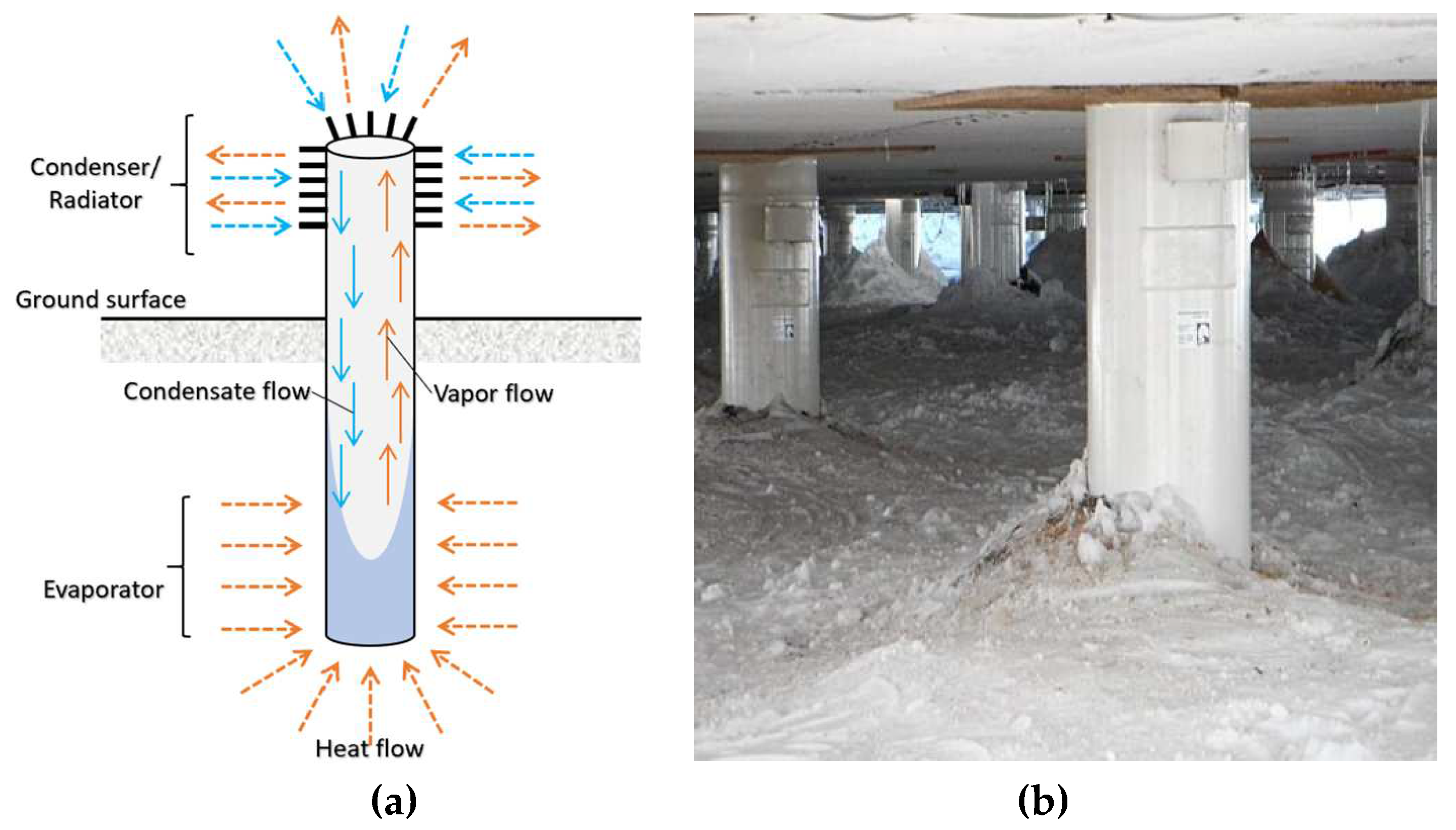
Figure 2.
(a) Illustration of a concrete spread footing foundation with a thermosyphon (Drawings are not to scale); (b-c) Use of Flat Loop Thermosyphons in Nome and Point Lay, Alaska. Retrieved from https://arcticfoundations.com/. Accessed on Dec 16, 2023.
Figure 2.
(a) Illustration of a concrete spread footing foundation with a thermosyphon (Drawings are not to scale); (b-c) Use of Flat Loop Thermosyphons in Nome and Point Lay, Alaska. Retrieved from https://arcticfoundations.com/. Accessed on Dec 16, 2023.
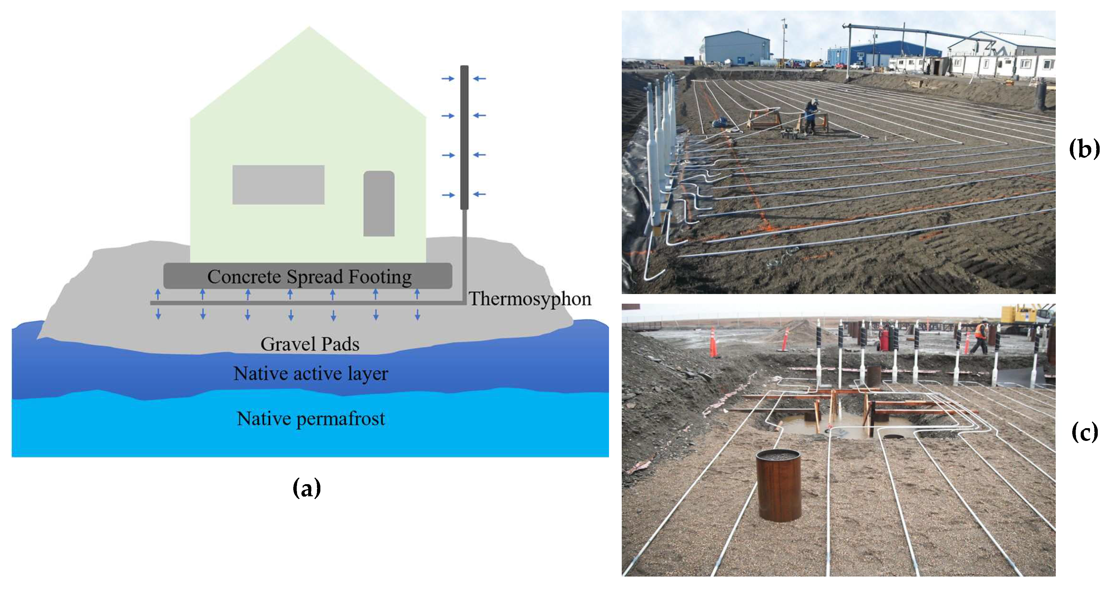
Figure 3.
Example of a possible footing foundation (adapted from McFadden [16]).
Figure 3.
Example of a possible footing foundation (adapted from McFadden [16]).
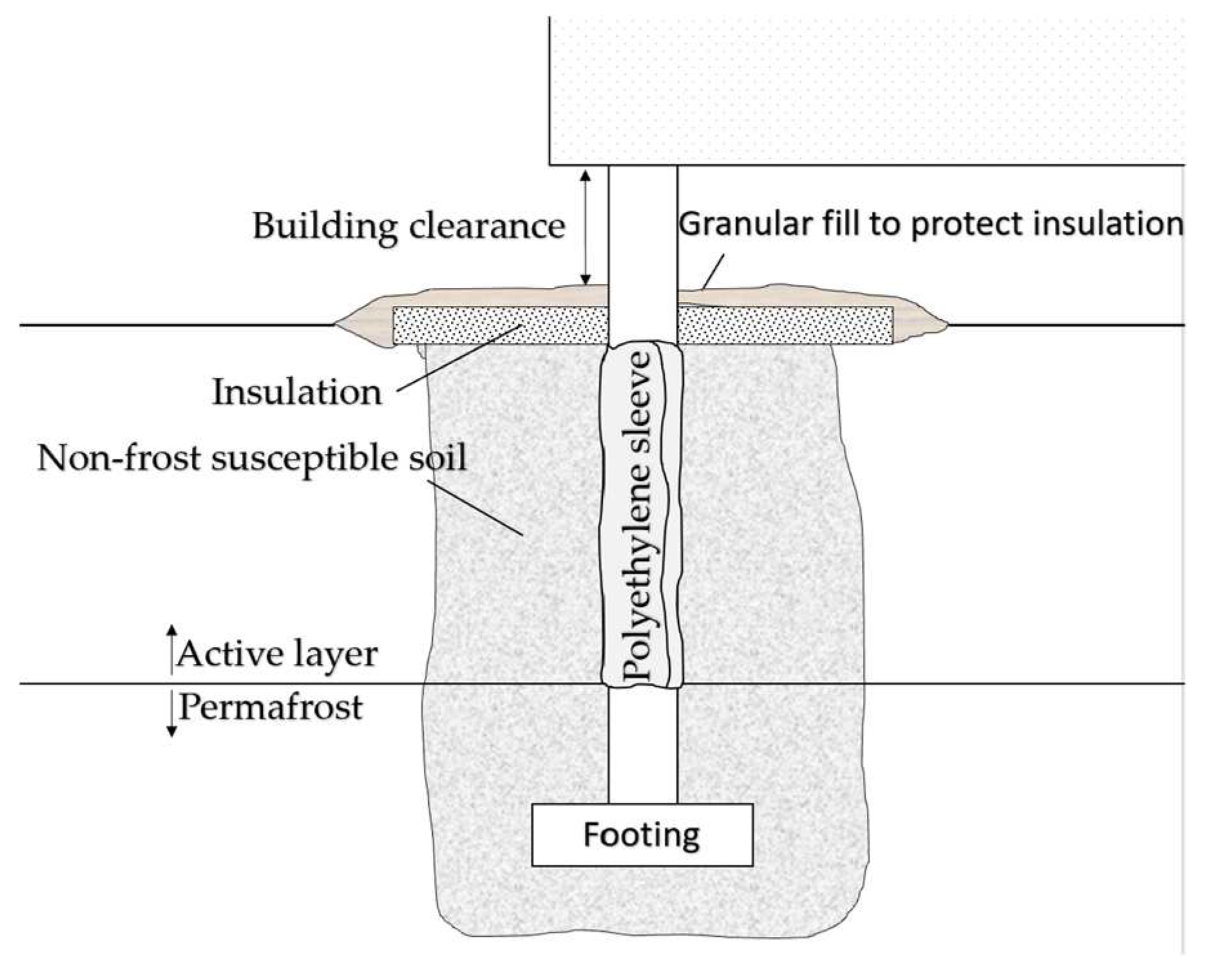
Figure 4.
(a) Example of footing in permafrost embedded in an insulated gravel pad on the ground surface (adapted from Johnston [17]); (b) a building in Inuvik supported on spread footing covered by gravel with possible ventilated ducts.
Figure 4.
(a) Example of footing in permafrost embedded in an insulated gravel pad on the ground surface (adapted from Johnston [17]); (b) a building in Inuvik supported on spread footing covered by gravel with possible ventilated ducts.
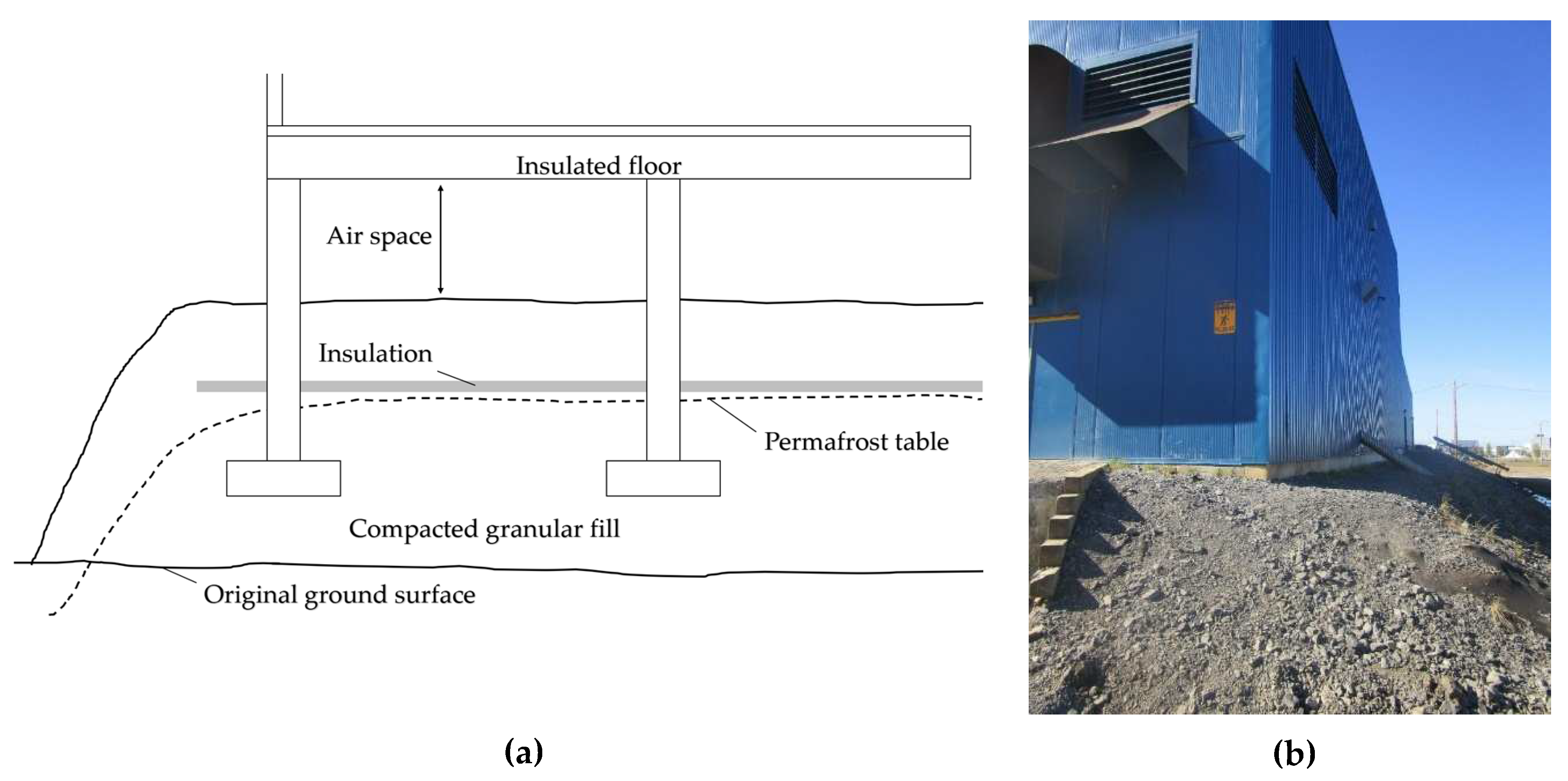
Figure 5.
Wood blocking system supporting a building structure in Inuvik, NWT, Canada
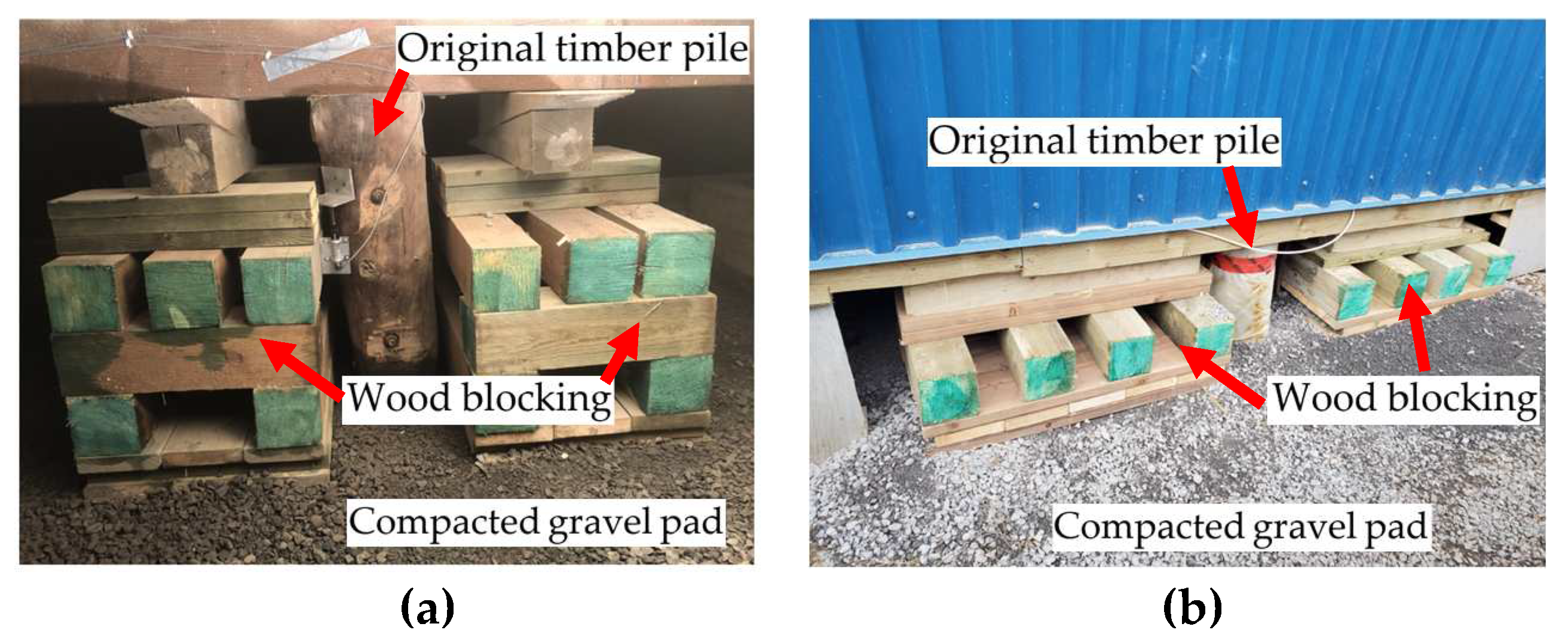
Figure 6.
Vertical gaps caused by the seasonal weather between the wood block wedge and building base floor beam.
Figure 6.
Vertical gaps caused by the seasonal weather between the wood block wedge and building base floor beam.
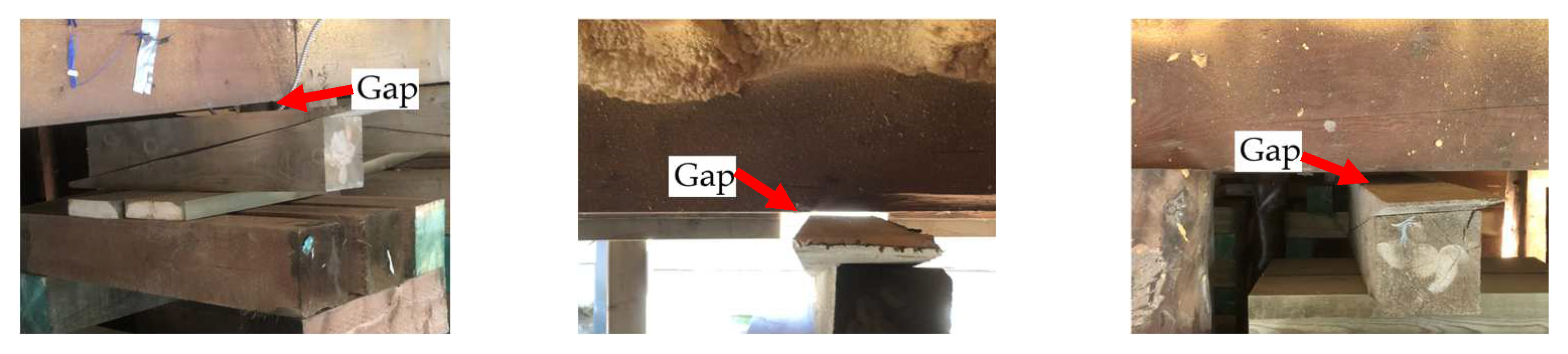
Figure 7.
The use of screw jacks in permafrost can be seen in the construction of the "igloo" church in Inuvik, Canada [20].
Figure 7.
The use of screw jacks in permafrost can be seen in the construction of the "igloo" church in Inuvik, Canada [20].
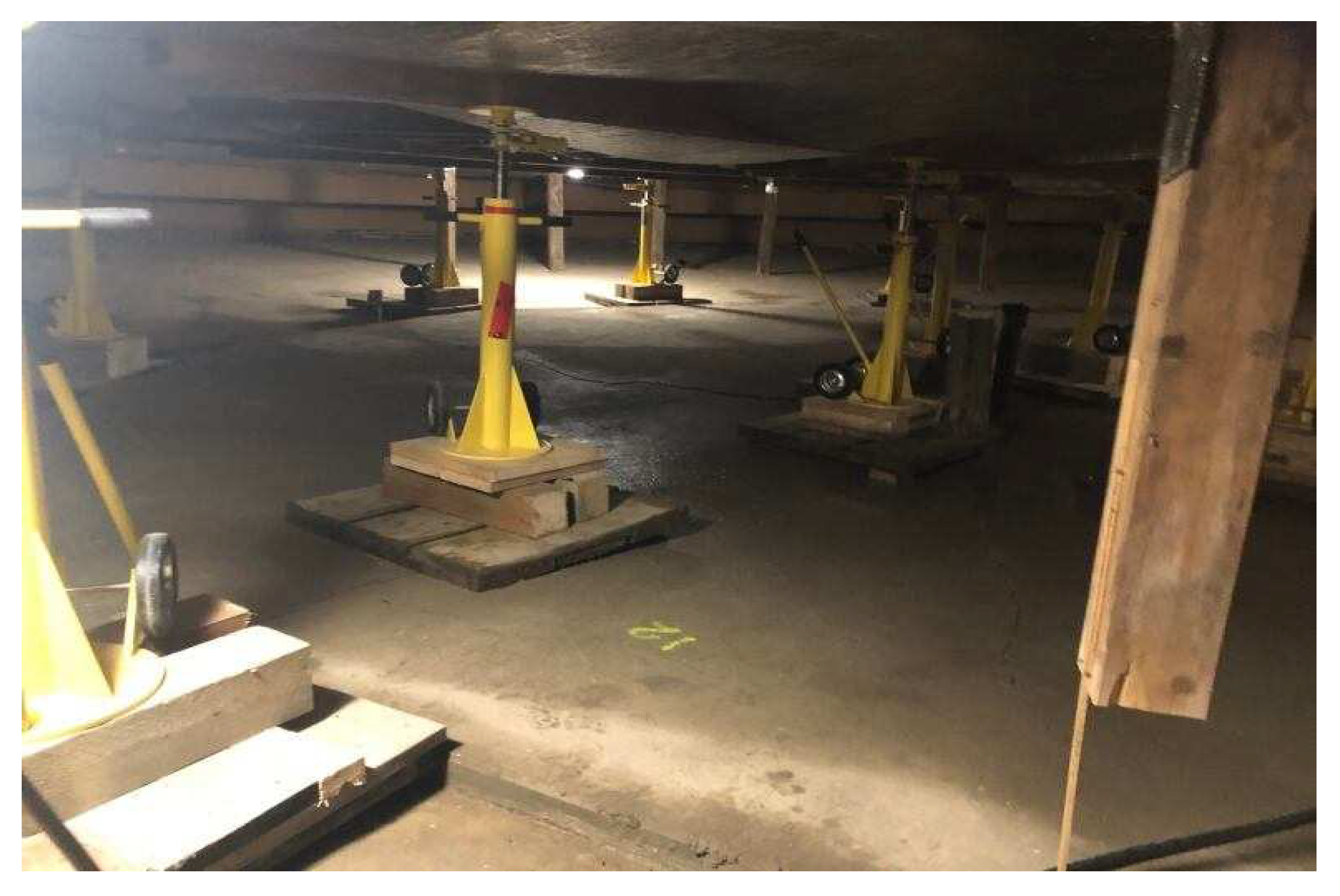
Figure 8.
Schematic detail showing the flexible connections and joints that allow the structure to move and shift. Retrieved from http://multipoint-foundations.com. Accessed on Dec 16, 2023.
Figure 8.
Schematic detail showing the flexible connections and joints that allow the structure to move and shift. Retrieved from http://multipoint-foundations.com. Accessed on Dec 16, 2023.
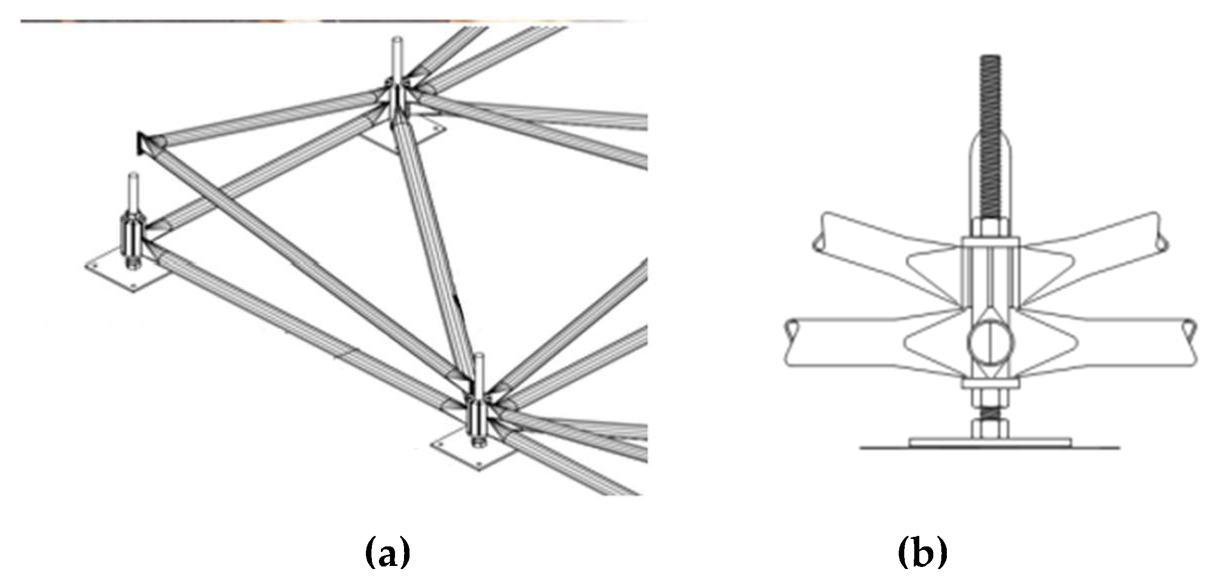
Figure 9.
(a) Foundation detail in slope terrain; (b) foundation detail functioning as a rigid slab under frost heave. Retrieved from http://multipoint-foundations.com. Accessed on Aug 16, 2023.
Figure 9.
(a) Foundation detail in slope terrain; (b) foundation detail functioning as a rigid slab under frost heave. Retrieved from http://multipoint-foundations.com. Accessed on Aug 16, 2023.
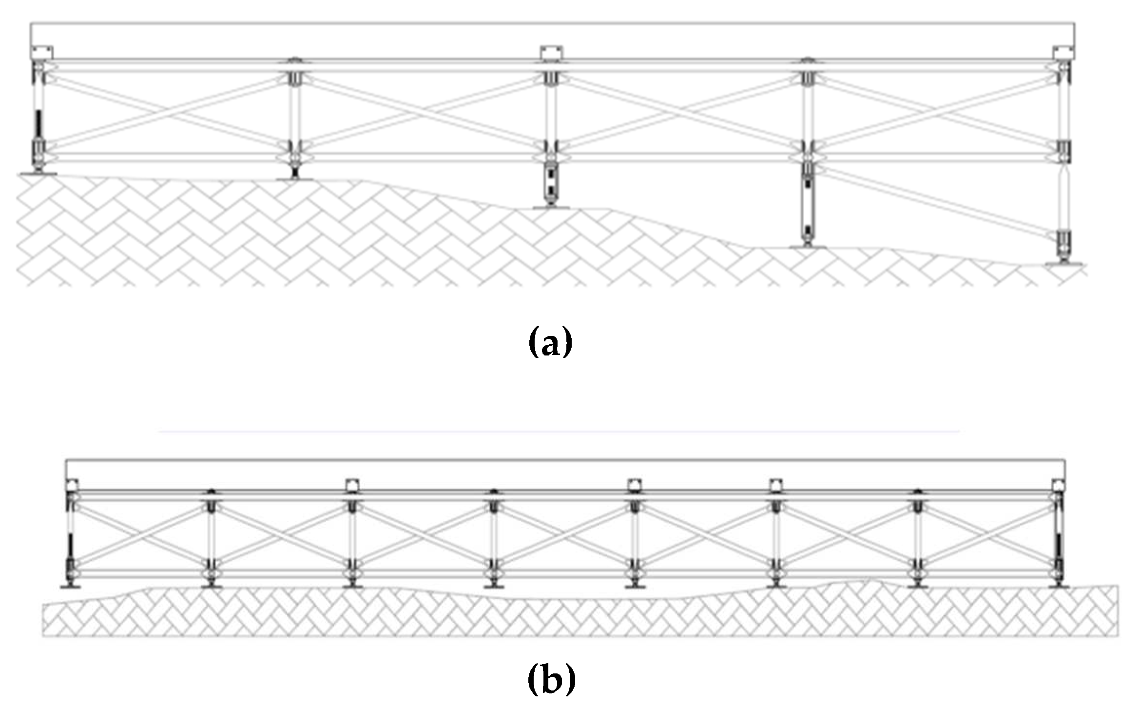
Figure 10.
(a) residential construction using a timber pile foundation in Inuvik, NWT, Canada; (b) tuck tape protecting timber from the water.
Figure 10.
(a) residential construction using a timber pile foundation in Inuvik, NWT, Canada; (b) tuck tape protecting timber from the water.
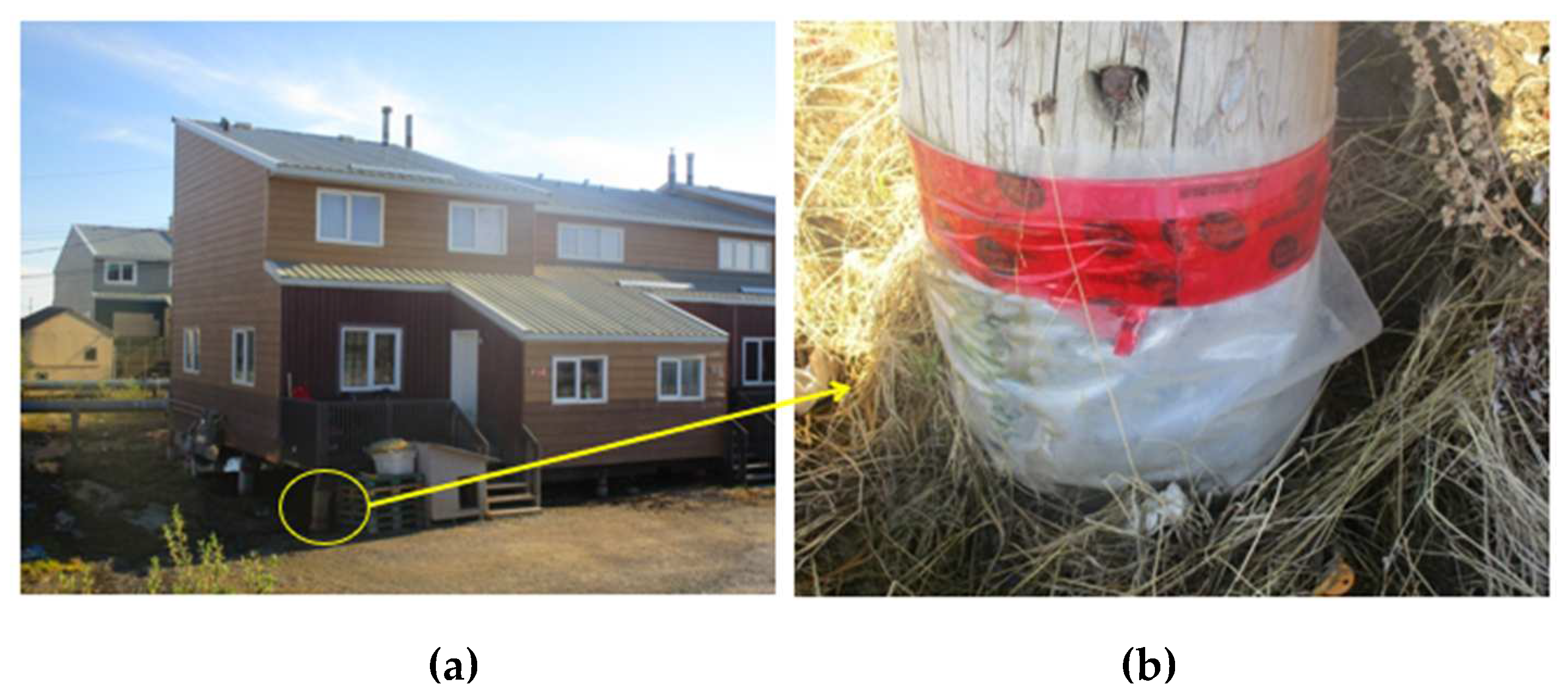
Figure 11.
Typical steel pipe pile foundation in Permafrost with backfill.
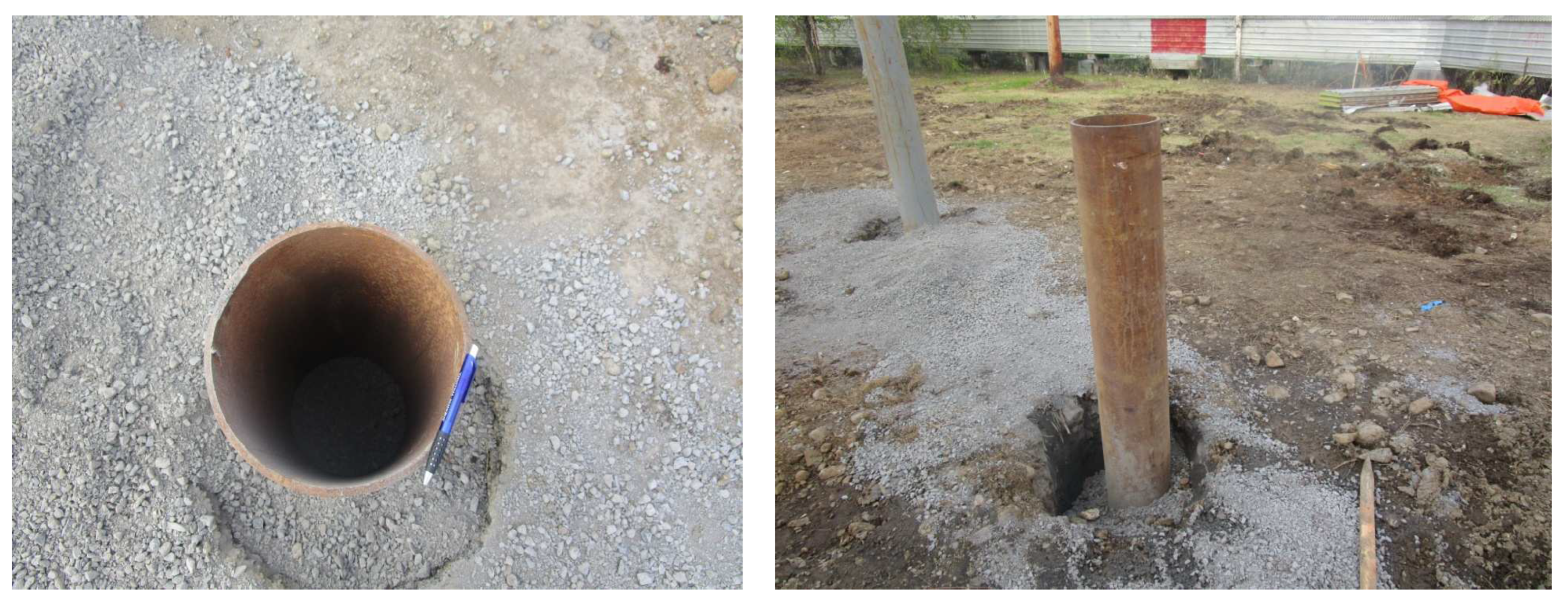
Figure 12.
Installation of the first thermopile in 1960 [27].
Figure 12.
Installation of the first thermopile in 1960 [27].
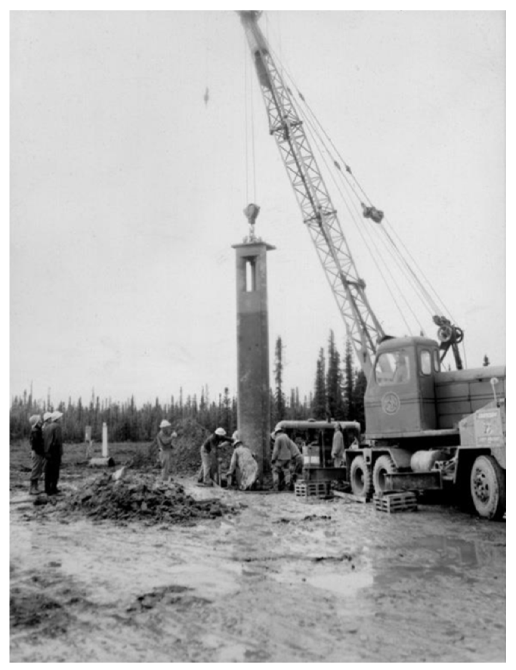
Figure 13.
Example of forces acting on a Screw pile acting as an anti-jacking force (adapted from Wang et al. [29])
Figure 13.
Example of forces acting on a Screw pile acting as an anti-jacking force (adapted from Wang et al. [29])
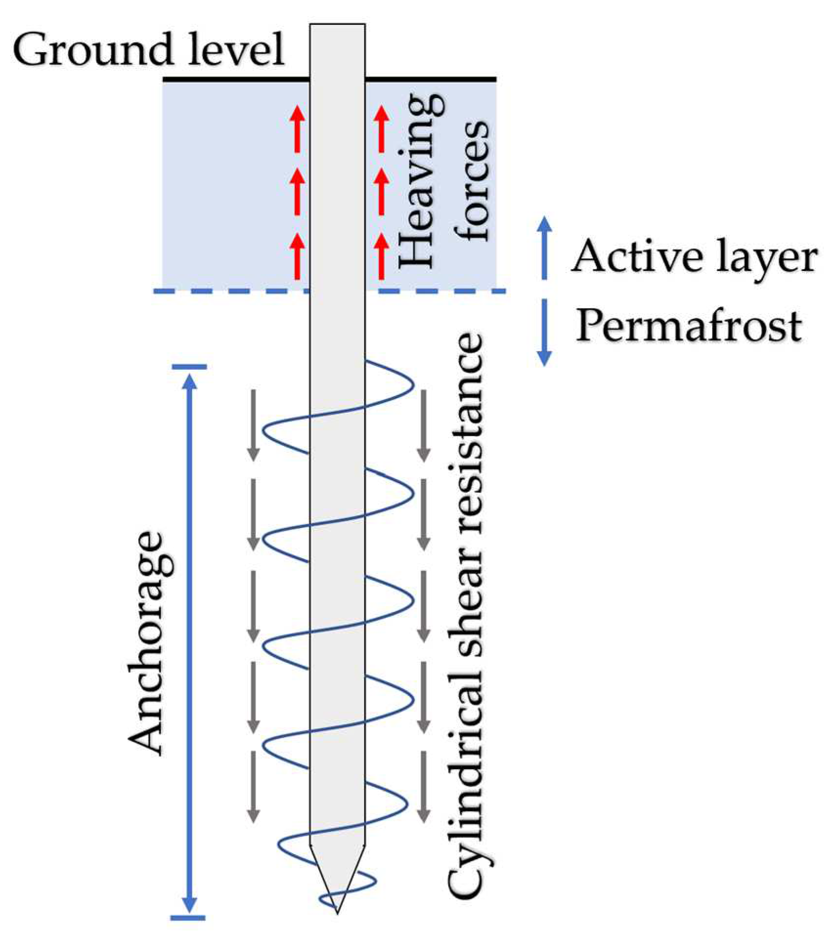
Figure 14.
A commercial building in Inuvik, NWT, Canada, and foundation.
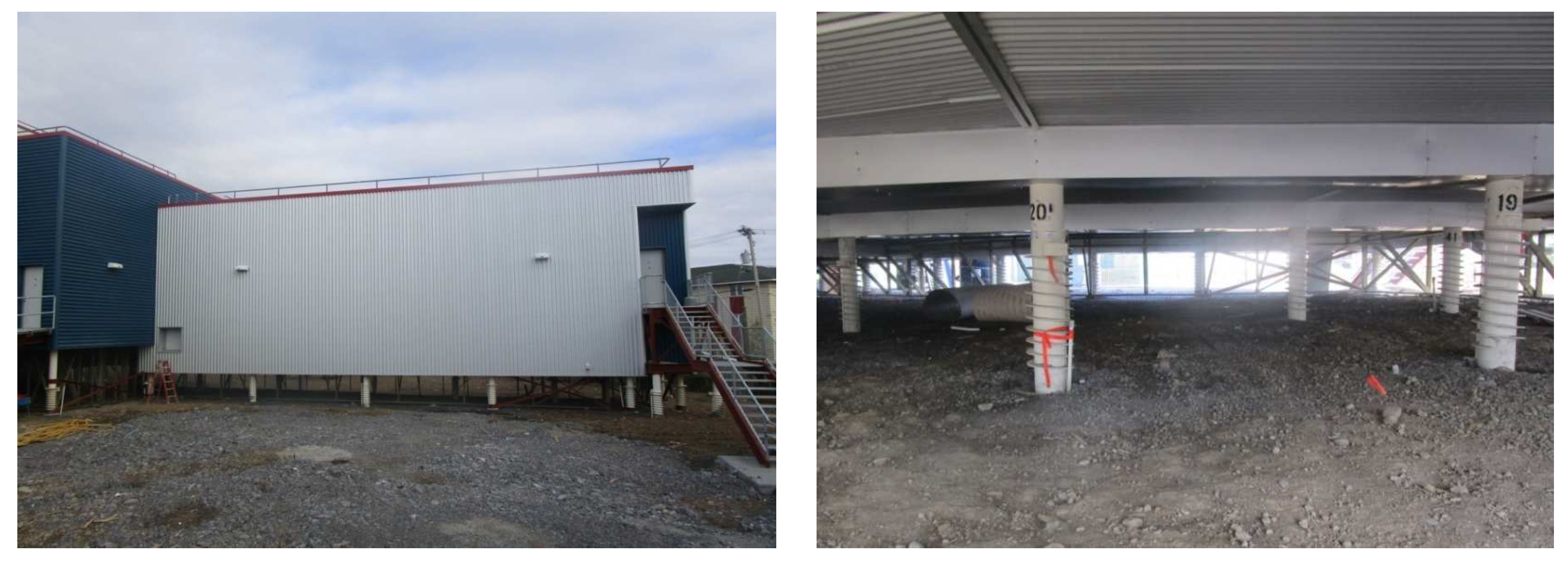
Figure 15.
Ground temperature envelopes at two sites near Inuvik, Northwest Territories in late August 2006, mid of December 2006, and early April 2007 (adapted from Kanigan et al. [30]).
Figure 15.
Ground temperature envelopes at two sites near Inuvik, Northwest Territories in late August 2006, mid of December 2006, and early April 2007 (adapted from Kanigan et al. [30]).
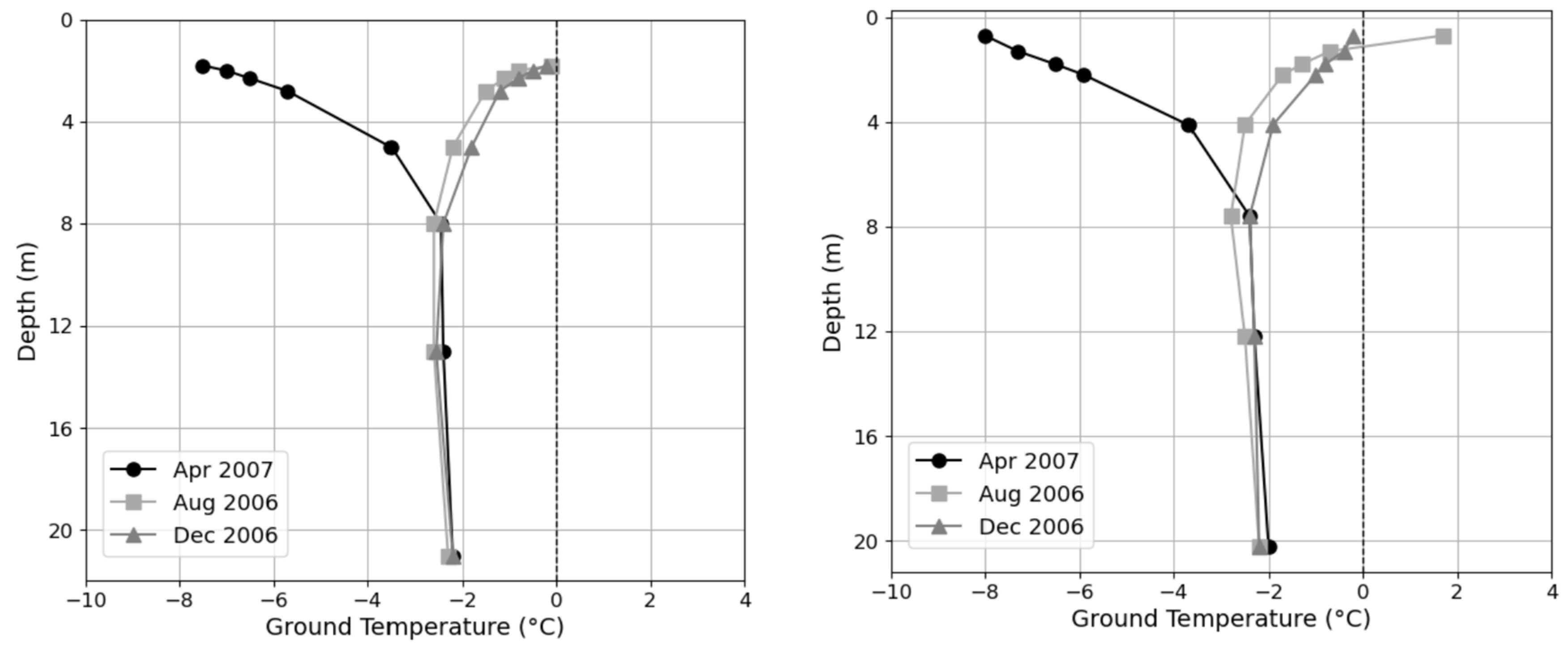
Figure 16.
Schematic of a screw pile embedded in permafrost.
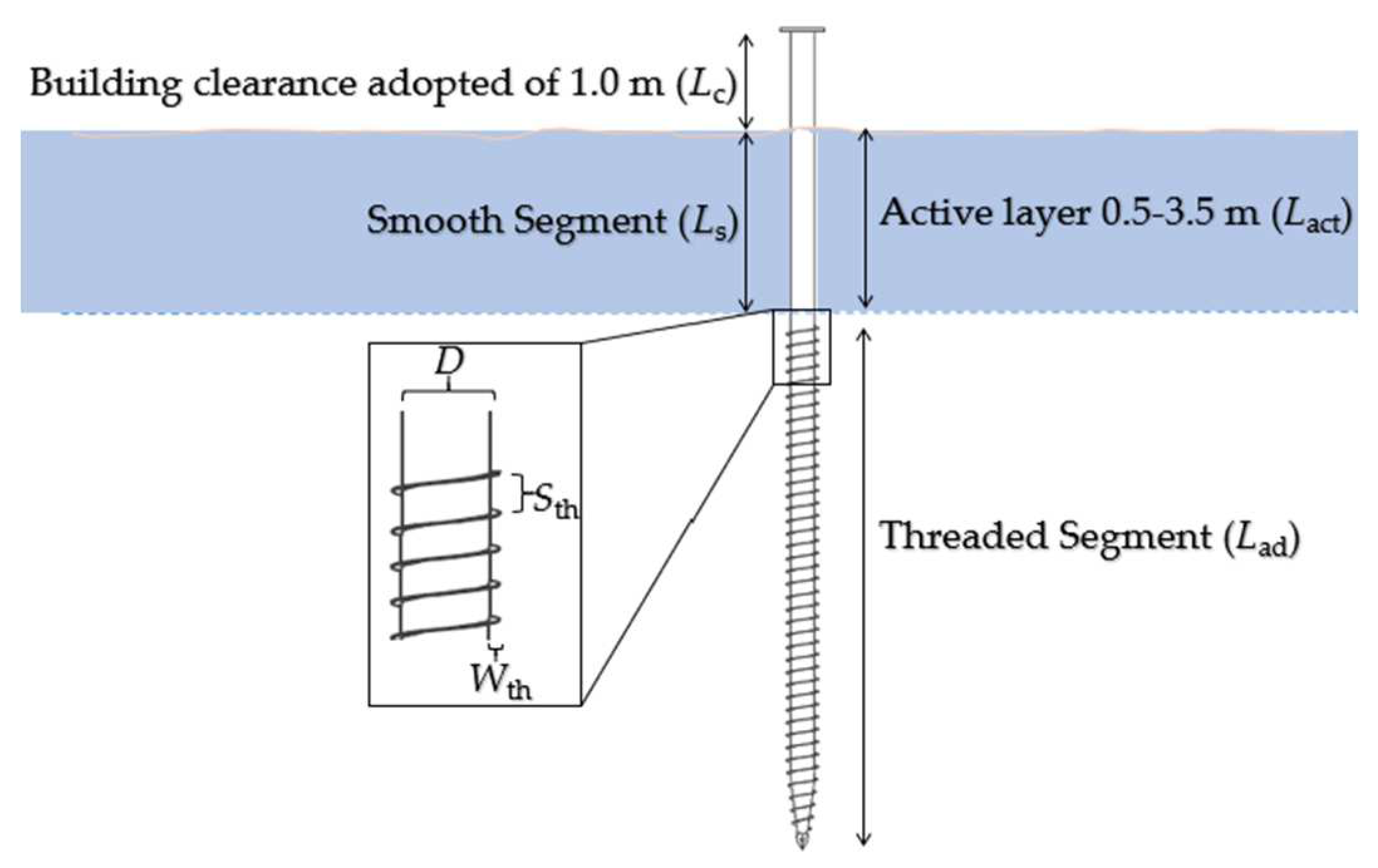
Figure 17.
Long-term cohesion of frozen soils [36]
Figure 17.
Long-term cohesion of frozen soils [36]
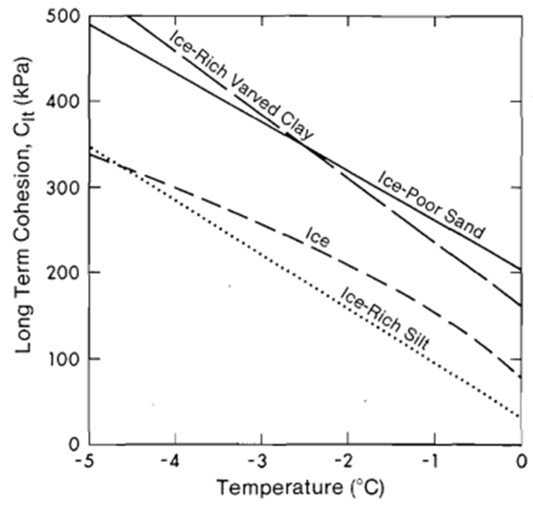
Figure 18.
Forces acting on a screw pile during the frost heave.
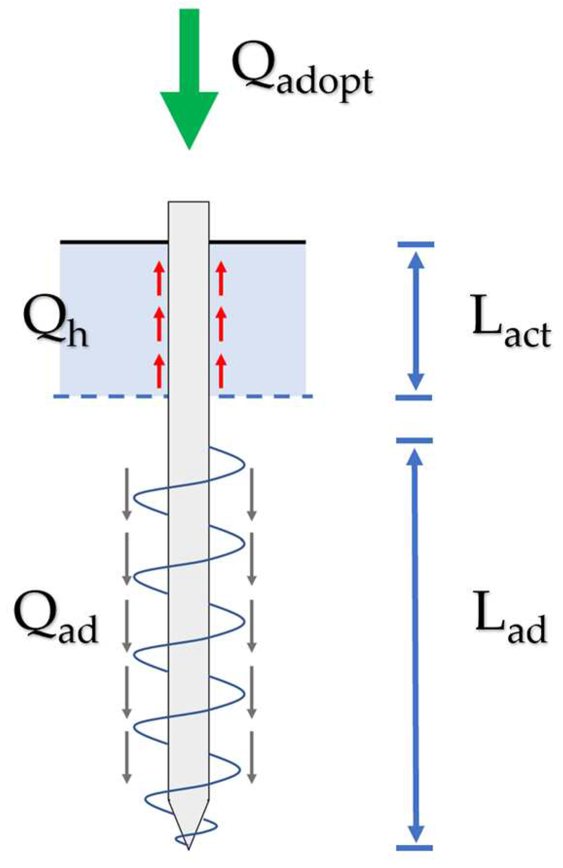
Figure 19.
Minimum pile lengths for screw piles and steel pipe piles for each design criterion.
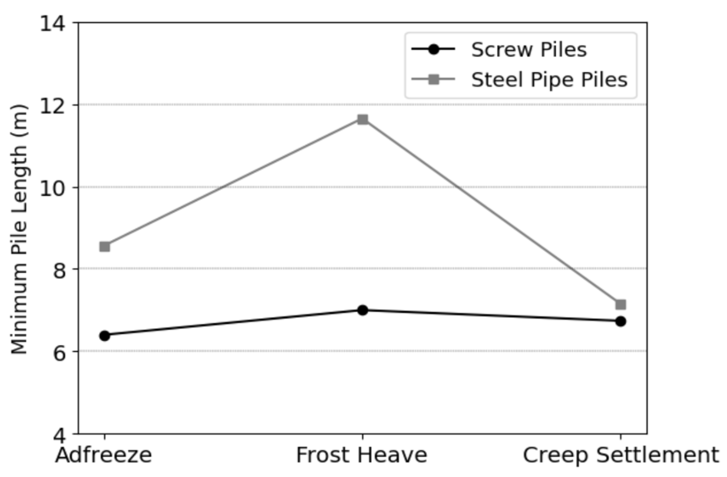

Table 1.
Changes in Air and Ground Temperatures from the 1850s to the 2090s (adapted from Zhang et al.[3]).
Table 1.
Changes in Air and Ground Temperatures from the 1850s to the 2090s (adapted from Zhang et al.[3]).
| Soils Depth | Temperature changes (oC) | |||
|---|---|---|---|---|
| From 1850s to the 1990s | From 1990s to the 2090s | |||
| Scenario 1 | Scenario 2 | Scenario 3 | ||
| 0 m | 1.6 | 2.8 | 3.8 | 7.0 |
| 0.2 m | 1.3 | 2.2 | 2.7 | 5.1 |
| 2 m | 1.0 | 2.2 | 2.5 | 4.6 |
| 10 m | 0.8 | 2.0 | 2.3 | 3.9 |
| 40 m | 0.3 | 1.4 | 1.6 | 2.3 |
Table 2.
Comparison between different types of foundations in permafrost
| Parameters | Footings | Jack Pads | Space Frame System | Timber Piles | Steel Pipe Piles | Screw Piles |
|---|---|---|---|---|---|---|
| Installation Methods | Trench excavation, concrete pouring, backfilling, reinforced steel | Assembly of prefabricated components | Assembly of prefabricated components | Hammering or driving piles into the ground | Excavation, driving or vibrating piles into the ground, grouting. | Screwing piles into the ground |
| Use of Heavy Equipment | Low | None | Low | High | High | Moderate |
| Load Capacity | Low | Low | High | Moderate | High | High |
| Soil Disturbance | High | Low | Low | Moderate | Moderate | Low |
| Vulnerability to Freeze-Thaw Instability | High | Low | Low | High | Moderate | Low |
| Reliability and Longevity | Moderate | Moderate | High Potential | Low | High Potential | High Potential |
| Differential Movement Between Supports | High Potential | Moderate | Low | High Potential | Moderate | Moderate |
| Material Availability and Shipping | High | High | High | Low | Low | Low |
| Availability of Qualified Contractors | High | High | Low | High | High | High |
| Building Type | Residential | Residential | Residential and Commercial | Residential and Commercial | Residential and Commercial | Residential and Commercial |
Table 3.
Shear stress and factor of safety adopted for screw piles and steel pipe piles for each design criterion.
Table 3.
Shear stress and factor of safety adopted for screw piles and steel pipe piles for each design criterion.
| Pile type | Parameters | Criterion | ||
|---|---|---|---|---|
| Adfreeze | Frost Heave | Creep Settlement | ||
| Screw Pile | Average τad or τ required (kPa) | 140 | 140 | 43.5 |
| FS | 2 | 1.5 | Not applicable | |
| Steel Pipe Pile | Average τad or τ required (kPa) | 84 | 84 | 47.2 |
| FS | 2 | 2 | Not applicable | |
Disclaimer/Publisher’s Note: The statements, opinions and data contained in all publications are solely those of the individual author(s) and contributor(s) and not of MDPI and/or the editor(s). MDPI and/or the editor(s) disclaim responsibility for any injury to people or property resulting from any ideas, methods, instructions or products referred to in the content. |
© 2024 by the authors. Licensee MDPI, Basel, Switzerland. This article is an open access article distributed under the terms and conditions of the Creative Commons Attribution (CC BY) license (http://creativecommons.org/licenses/by/4.0/).
Copyright: This open access article is published under a Creative Commons CC BY 4.0 license, which permit the free download, distribution, and reuse, provided that the author and preprint are cited in any reuse.


