Submitted:
16 January 2024
Posted:
17 January 2024
Read the latest preprint version here
Abstract
Due to satisfactory mechanical properties, low specific weight and other advantages, a substantial utilization of laminated structural composites in many components and equipments of several industry sectors, especially in the past two decades, has been made. This class of materials has a good potential to be an important ally to support scientists and engineers with the main current world challenge: an energy transition process that must occur with sustainability, eco-friendly materials and based on an efficient reduction of greenhouse gas emissions. In this context, a microanalysis (scale length: 10μm to 1mm) of mechanical behavior that considers the multiphase characteristics, at leastwise a matrix and a reinforcement phase, of this kind of composites must be explored, i. e., a heterogeneous material is assumed to predict, for example, the effective tensors of stiffness or compliance by a homogenization process, modeling to damage analyses, studies about progressive delamination and other specific aspects of a composite can be previously investigated using micromechanical approaches. Therefore, the understanding of fundamental micromechanics as well as some advanced models are essential to apply these materials in structural industry components. In this sense, this systematic literature review is designed to investigate the main basic and advanced models of laminated composites micromechanics and using this overall study, have been developed, in the end, an analysis of research trends to the topic, in which, lines to future researches are indicated.
Keywords:
micromechanics
; polymer laminated composites
; heterogeneous material
; homogenization
1. Introduction
With the marked technical-scientific development in composite materials, mainly from the 1970s, several industrial sectors began to incorporate this class of materials in their components, in particular, because they present satisfactory specific mechanical properties, given their low density in comparison to steel, for example, until nowadays typically used in structural applications [1].
Currently, the great technological challenge of the energy transition needs to be faced by engineers and scientists and at the same time, there is also the process of greenhouse gas emission reduction. In this complex context, the application and research focused on laminated composites gains even more encouragement in the industrial and academic areas, as this class of multiphase materials is seen as an excellent alternative for structural parts and components in the renewable energy sectors, including, with regard to minimizing CO2eq emissions throughout the life cycle of their equipments [2].
Given this favorable scenario for structural laminated composites, it is of utmost importance to further develop the knowledge about the several thermomechanical behaviors that they can present. Therefore, as they are multiphase materials, this heterogeneity needs to be better accounted for the prediction of effective properties necessary for the macro analysis of a structure made up of these kind of composites. The purpose of micromechanical modeling focused on these laminates is to make a theoretical determination as to what would effectively be the homogenized characteristic tensors that should be used into the constitutive relations of these materials [3].
Aiming to provide a broad overview of micromechanical models for the laminated composite analyzes, this research is designed to review the fundamental modeling, that is, the most elementary and precursors models in the development of this branch of solid mechanics, as well as exploring the state of the art models whose proposals have been published in recent years and, finally, this study presents trends for future researches involving the topic.
In this sense, the research shows highlighted elementary models highlighted in the literature, such as: Voigt and Reuss models (mixture rule), the Chamis model, Bridging, the modeling by Eshelby equivalent inclusions, the Mori-Tanaka method, the model for predicting elastic constants in fabric-reinforced composites, as well as citations made to conventional numerical models.
Regarding the advances achieved in the past years and more recent proposals, the following stand out: reformulations for the high-fidelity generalized cell model, including the use of continuum damage mechanics to analyze the nucleation of discontinuities in the material, the multilayer concentric cylinder method, approaches including the cohesive zone model for evaluating the initiation of interlaminar failures, modeling that study the micromechanical mechanisms associated with delamination, models for inelastic behavior prior to failure, dynamic models, approaches for progressive microdamages analysis based on non-local continuum mechanics and stochastic models.
2. Literature Review
2.1. Fundamentals and Previous Studies
All material, at a certain scale of analysis, can be classified as heterogeneous. The major contribution of micromechanics is to consider the heterogeneity of the material while allowing it to be represented as a pseudo-homogeneous continuum in analyzes referring to larger length scales (structural sizes) [4].
The concepts of representative volume elemento (RVE) and repeated unit cell (RUC) are important in microanalysis. RVE concerns a volume with sufficient dimensions to consider the constituent microstructure of the material and, at the same time, that is representative of the material as a whole in terms of effective mechanical behavior, that is, when applying a tension or a displacement as boundary conditions to this RVE, its mechanical behavior would be the same as that of the material on a global scale (for a perfectly homogeneous material, this volume could be much smaller). The RUC concept establishes the existence of a standard microstructure that is repeated throughout the volume of the material, i. e, it considers the microstructure as periodic [4].
The properties of a lamina or assembled laminate can be determined experimentally or designed and predicted mathematically based on the properties of the constituents of the continuous and dispersed phases by a micromechanical modeling. As will be seen, the purpose of all smaller-scale analysis is to determine how the constituent elements of the material interact mechanically and contribute to the final properties of the composite, for example, the moduli of elasticity, compliance or elastic stiffness in terms of the properties of reinforcement and matrix elements, equation (1) [3]:
where, is the modulus of elasticity of an isotropic fiber, is Poisson’s ratio and is the ratio between the volume of fibers and the composite volume, being the respective analogues of the material that makes up the matrix [3].
By considering simplifying hypotheses that enable an effective modeling to the mechanical behavior of the composite, the mechanics of material approach to determining stiffness is common and practical. The most prominent hypothesis among those that set up this model is the one that considers the same strains for fiber and matrix when there is load in the direction of the reinforcing fiber in a unidirectional laminated composite. This hypothesis is reasonable, since if there were no this motion condition, there would be a detachment or rupture between the two components [3].
Based on the aforementioned hypotheses is the Voigt model, which leads to the rule of mixture for the composite stiffness tensor components. For a two-phase material, could be written [4]:
where, is the volume fraction of the matrix phase, is the volume fraction of the reinforcement phase, is the stiffness tensor of the matrix phase, constitutes the stiffness tensor of the reinforcement phase and C is the effective stiffness tensor of the composite [4].
The Reuss approximation assumes that the stresses acting on the different phases of the composite are uniform and equal to the average stresses, this implies the rule of mixture to the compliance tensors [4]:
where, is the volume fraction of the matrix phase, is the volume fraction of reinforcement phase, is the compliance tensor of the reinforcement phase, is the compliance tensor of the reinforcement phase and S is the effective compliance tensor of the composite [4].
The limitation for the Voigt model is found in the stresses arising from the same strains for fiber and matrix do not bring the boundaries of these phases to an equilibrium condition. Regarding the Reuss model, it appears that strains arising from the hypothesis of uniform stresses that makes the cohesion of phases physically impossible [4].
In the specific literature, there are some authors who seek to combine the Voigt and Reuss models to reasonably predict effective properties of certain composites in engineering, even though the two models do not satisfy the basic equations of the classical theory of elasticity [4]. It is demonstrated by the so-called Hill’s Theorem that the Voigt and Reuss models provide upper and lower limits on the effective properties of the composite material.
The bounding theorems propose the establishment of narrower limits than Voigt and Reuss models predict for the material constant values, within which it is known that the effective elastic properties of the composites are adjusted. Considering the interaction of elastic properties of the constituent phases and not just the volume fractions, it is clear that for a two-phase composite, in which the axis of symmetry for the transversely isotropic effective material coincides with the longitudinal direction, the relationship obtained for the elastic modulus was [4]:
where, in addition to the already described volume fractions of the matrix and reinforcement constituents, there are:> as the bulk modulus of matrix and fibers, respectively, shear moduli of the dispersed and cohesive phases, and are the respective Poisson’s ratios of matrix and fibers, EL is the effective longitudinal elastic modulus of the composite and and are also the respective longitudinal elasticity moduli of matrix and reinforcement [4].
The Halpin-Tsai approach consists of a semi-empirical model that provides better fits between theoretical prediction and experimental results for both the effective elastic modulus transverse to fibers (ET), as for effective shear modulus (GLT) in the plane that contains the longitudinal and transverse directions to the fibers as indicated in Figure 1, that represents in-plane shear modulus [5].
According to the Halpin-Tsai model, could be written [5]:
With
is the so-called reinforcing factor, which is a function of fiber geometry, fiber packing geometry and loading conditions [5].
Using the classical elasticity theory and the so-called average strain and average stress theorems for a RVE, it is shown using homogeneous boundary conditions and considering perfect cohesion at the interface and that the effective elasticity and compliance tensors for a two-phase material can be approximated by [4]:
In which and are the effective stiffness and compliance tensors for the two-phase composite, and are the strain and stress tensors induced by the homogeneous displacement boundary conditions and loading, respectively. and are the average strain and stress tensors over the volume occupied by the reinforcement phase [4].
The so-called dilute approximation is a modeling that disregards the interaction between inclusions, then, the multiphase material can be assumed as a single inclusion embedded in continuous phase. Based on this hypothesis, for example, the effective bulk modulus, equation (11), for spherical inclusions can be demonstrated [4].
In which, is the volumetric fraction of concentration of the diluted inclusions, are the bulk modulus of the matrix, of the inclusion and one of the Lamé constants for the matrix, respectively.
The Mori-Tanaka Theory (MT) has proven to be relevant in many studies that search to determine the effective behavior of composite materials. This theory is based on the calculation of average internal stresses and strains in the matrix of a material containing precipitates using the concept of eigenstrains [4,70]. Then, the effective stiffness tensor for a two-phase composite can be described by:
where, is a concentration tensor associated with the linear transformation between the strain tensor induced by homogeneous displacement boundary conditions and the average strain tensor for the dispersed phase [4,70].
Hence, the Mori-Tanaka theory originally considers that the interactions within the composite caused by the inclusions of the dispersed phase can be approximated by a single inclusion in the infinite matrix of the continous phase, which is subjected to the average strain tensor , i.e., the volumetric concentration of inclusions needs to be small for the model to have a satisfactory approximation [4,70].
The text written by Aboudi et al [4] even highlights an elementary micromechanical model called differential schemes (DS). In this differential model, a two-phase composite of initial volume , first of all, has an increment of volume removed. This fact implies a corresponding removal of inclusion/reinforcement . Consecutively, instead of this volume of composite removed, the same amount of inclusion/reinforcement is added . Consequently, the current volume of the dispersed phase is:
Which, in differential form, is [4]:
And, also based on equation (11), what the differential model proposes is that the effective stiffness tensor of the composite in a new volume fraction of fibers is approximated to [4]:
where a small volume of inclusions/reinforcements, whose stiffness tensor is , are homogeneously embedded in a continous phase of stiffness given by , therefore, in differential form can be written [4]:
With when [4].
The Eshelby’s equivalent inclusion method works with inclusion in the ellipsoidal form embedded in an infinite matrix phase, i.e, the homogeneous boundary conditions act so far from the inclusion. The solution for the effective elastic properties based on the principle of equivalent ellipsoidal inclusion can be derived for different other geometries, such as: spheres, cylinders with an elliptical base, possible cracks, etc. [4,59,67].
The Eshelby approximation considers an infinite homogeneous matrix whose stiffness tensor is and which contains an ellipsoidal domain Ω with an eigenstrain (it could be a thermal strain, for example). As the natural change in the geometry of this domain Ω is restricted to matrix contours, a stress field develops that can be expressed by [4,59,67]:
where, is the total strain given by the sum of the eigenstrain and the elastic strain induced by the stresses. Eshelby showed that if it is uniform in this domain, then, it is also uniform in it and both strains are related through the so-called Eshelby tensor (P), whose components are functions of elastic constants and geometry of the inclusions [4,59,67]:
When an infinite matrix containing this ellipsoidal domain Ω is subjected to a homogeneous boundary condition of displacements, the total stress tensor is given by [4,59,67]:
Then, the Eshelby model replaces the ellipsoidal domain whose stiffness is given by the tensor by an equivalent stiffness inclusion such that [4,59,67]:
Using the concept of equivalent inclusions of Eshelby in the Mori-Tanaka method, a three-phase model for this theory assumes the presence of an intermediate phase between the fiber and the matrix. Using multiple inclusions, the explicit formulation of this model is given by [5]:
where the terms are the volume fraction, the stiffness tensor and the concentration tensor of the intermediate phase, respectively.
In which and are the Eshelby tensors for the domains of the intermediate and reinforcement phases, respectively. For a cylindrical inclusion of reinforcement-intermediate phase in an isotropic matrix, it is expressed by [5]:
For a cylindrical inclusion of reinforcement-intermediate phase in an isotropic matrix, the elements of are expressed by [5]:
And for a cylindrical reinforcement/fiber inclusion in an intermediate phase, the elements of tensor are given by [5]:
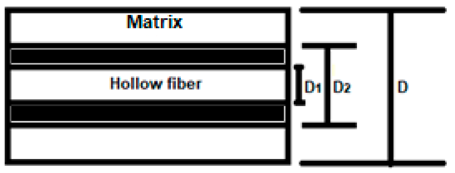
The cylindrical composite assemblage model aims to determine the effective elastic modulus of composites with hollow circular fiber alignments. For a hexagonal arrangement, the following prediction was obtained for the effective longitudinal modulus of elasticity of the composite [5]:
Where:
Figure 2.
Cylindrical hollow fiber as matrix reinforcement and respective internal and external diameters of the fiber and matrix [5].
Figure 2.
Cylindrical hollow fiber as matrix reinforcement and respective internal and external diameters of the fiber and matrix [5].
Kumar et al [6] develop a model also considering three phases (matrix, interface and unidirectional fibers). For physical modeling, researchers assume that the interface is an isotropic and homogeneous material, thus, elastic constants such as and damping coefficients can be obtained from the related mathematical model. From the calculations performed, the study shows that the volume fraction of the interface, as well as, its determined properties, generate a significant effect on the loss factor of the composite and, in the end, conclude that the results of the proposed model present acceptable congruence with the modeling numerical performed by finite elements [6].
The method of cells approach assumes uniform and aligned spacing for the fibers in a matrix, meaning that the composite can be viewed as a periodic matrix arrangement in transverse directions to the fibers. In this model, each cell corresponds to the representative volume element and is composed of subcells as indicated in Figure 3 [5].
The volume of each cell can be expressed by [5]:
Where are the length, width and height of each subcell identified by subindexes b and c. Therefore, the cell volume is given as follows [5]:
Where,
Applying Hooke’s law to each subcell, can be written [5]:
As each cell represents a representative volume element for the composite, the average strains and stresses for each of them can be written as follows [5]:
Then, applying now Hooke’s law for a cell of the composite material, it can be expressed by equation (32) [5]:
Where, is the effective stiffness tensor, with representing the strain concentration matrix of each subcell. An extension to global coordinates of a laminate can also be seen in [5].
In research aimed at predicting progressive failures in multidirectional laminated composites, Basu et al [7] (noting that local rotations combined with the continuous degradation of the matrix are the mechanisms responsible for fiber microbuckling) develop a modeling based on the so-called Schapery theory. Thermodynamically based, this theory assumes internal state variables in order to analyze the evolution of damage in laminated composites.
According to this theory, the total work is composed of inelastic work and deformation work . The portion of the total energy that is not returned () can be obtained from the material’s own response according to the stress-strain relationship displayed [7]. To satisfy the path independence condition for total work, these internal state variables ( must be compliant to equation (35) [7].
By definition,
Where, is the so-called thermodynamic force of the ith internal state variable , whose value represents the magnitude of force available through a load. When this force exceeds (necessary intensity), the material undergoes the structural change associated with the variable , then, there is (damage progress related to at a time), otherwise this temporal rate is null [7].
Initially, Schapery considered two internal state variables, one of them for the energy associated with microcracks in the matrix (S) and another for intra-layer transverse cracks (Sc), so, the inelastic work is written as follows [7]:
The study of Basu et al [7] only considers the irreversibility related to S, i. e, the energy dissipated due to the accumulation of microcracks in the matrix. The effects on the elastic modulus E22 and shear modulus G12 are given by:
In which and are the respective elastic moduli for the intact material, and are polynomial functions of the internal state variable S associated with microcracks [7].
Regarding the strain energy density or strain work, Basu et al [7] write:
To consider geometric nonlinearities, the Green strain tensor and the second Piola-Kirchoff tensor must be used in equation (38). It can be demonstrated that [7]:
In [7], the physical hypotheses of the model considerso, . It is assumed that the stiffness in the direction of the fibers is not influenced by S, then, and also that varies while remaining constant, thus, the equation (39) for damage evolution reduces to [7]:
Obviously, in inelastic processes the rate of entropy generation is non-negative (), given that physically a reversible damage is not allowed by the assumed mechanism [7].
Once established the theoretical basis for the model, Basu et al [7] suggest that the microbuckling phenomenon in fibers under compression load is accounted for by the rotation of the fiber at a given point in the material.
Where, is the contribution of applied external shear, if any. The angular variables and can change as a function of the far-field stresses [7].
After implementing of subroutine in ABAQUS and the good approximation of the simulation results with experimental data, the authors concluded that this model dispels the notion of a fixed compressive strength, specifically, it uses the mechanism of the failure process to provide the local compressive strength in given point of a lamina [7].
When studying specific models for determining effective elastic constants in fabric-reinforced composites, the modeling developed by Vasiliev and Morozov stands out. [8], which describe the typical structuring of knitted fabrics as a fabric in which warp yarns and weft or fill yarns are woven and to demonstrate the influence of the angle (α) on the modulus of elasticity of the material, the researchers consider a tension in the longitudinal direction and the rule of mixture for the fabric itself. It is worth mentioning that the magnitude of this elastic modulus of the fabric is, as a general rule, tens of times greater than that of polymer matrices, therefore, the authors assume it to be the apparent elastic modulus of the composite itself in that direction [8].
Where, is the apparent cross-sectional area, oriented with normal in the longitudinal direction. is the area of the section containing the transverse yarns (weft) and is the area of the section with longitudinal yarns (warp). After defining the geometric measurements associated with each area ( e ), the longitudinal elastic modulus of the composite is expressed as follows [8]:
It is noted that the fibers that make up the transverse direction yarns are orthogonal to the loading, so, it is assumed that the transverse modulus of elasticity in the fabric is equal to the transverse Young’s modulus in a unidirectional composite, i.e, and is the longitudinal elastic modulus of a unidirectional composite reinforced by the same fibers [8].
In according to Vasiliev and Morozov [8], if the same fibers in a generic arrangement of woven fabric form a cross-ply [0/90] composite, for example, they will give it an effective longitudinal elastic modulus greater than that of the woven fabric, just because the fibers, in cross-ply, are not under the pre-bending as in the woven fabric.
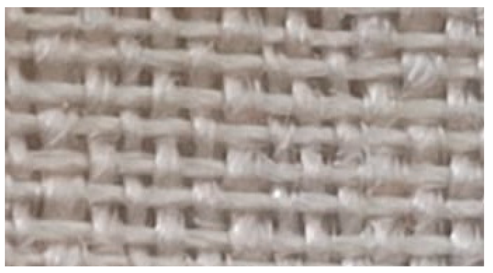
Despite this general decrease in the stiffness and resistance of composites reinforced by woven fabrics in relation to those of the [0/90] arrangement, in two particular types of weaves, practically the same properties are observed as in that cross-ply composites. These are plain and twill weaves. In plain weave, very common in the formation of woven fabrics, the longitudinal fibers are intertwined with the transverse fibers, passing repeatedly above and below them, so that, globally, there is a tendency to cancel out these pre-bendings of the fibers caused by the weaving [8].
Figure 4.
Photo taken by the first author. Illustrates the plain weave profile in fabric made with ramie fibers.
Figure 4.
Photo taken by the first author. Illustrates the plain weave profile in fabric made with ramie fibers.
The Bridging model works with a tensor (bridging tensor), which represents how able the continous phase is in sharing the external loading to the composite in relation to the dispersed phase [9], in other words:
In which, and they can be easily consulted, as well as specifications for their parameters, in the Wang and Huang paper [9].
Chamis is a model modified from the mixture rule, in which the longitudinal elastic modulus and in-plane Poisson’s ratio are identical to those determined by the aforementioned rule, the other constants are mathematically expressed as follows [9]:
Concluding the initial approach of this research upon fundamental micromechanical models for laminated composites, it is necessary to comment about some numerical models that are used in the calculations of the homogenizations proposed by micromechanical modeling. Well, a micromechanical finite element analysis (FEM) has acceptable computational costs in linear elasticity problems, however, when the matrix phase material presents non-linear behaviors, some other specific methods become more advantageous, such as: Voronoi cellular finite elements (VCFEM), the generalized method of cells (GMC), finite volume direct averaging micromechanics (FVDAM) and the asymptotic method for unit cell homogenization (VAMUCH) [9].
Confronting each othersome of the micromechanical models described previously, Table 1 below, in which the total average error involved in predicting five elastic constants () for each of these models is listed in ascending order in relation to their respective lack of accuracy [9].
It is worth noting that for the longitudinal elastic modulus () all models provide practically the same values, neverthless, for the other constants, it is observed that some approaches are sometimes superior, sometimes inferior compared to each other [9]. Therefore, the choice of one model or another to predict values of effective elastic constants in a composite must involve consideration of the degree of relevance for those constants that are more and less important in view of the final application of the material to be developed.

Table 1.
Total average error of some micromechanical models in predicting five elastic constants for composite materials [9].
Table 1.
Total average error of some micromechanical models in predicting five elastic constants for composite materials [9].
| model | Average Error | Rank |
| Bridging | 10.38% | 1 |
| FVDAM | 12.83% | 2 |
| FEM | 13.08% | 3 |
| Chamis | 14.09% | 4 |
| GMC | 15.07% | 5 |
| Halpin-Tsai | 19.24% | 6 |
| Mori-Tanaka | 19.59% | 7 |
| Rule of Mixture | 28.40% | 8 |
| Eshelby | 30.72% | 9 |
2.2. Advances and Recent Researches
In order to include the failure mechanisms of fiber-reinforced structural composites in processes of numerical simulation, a reformulated high-fidelity generalized method of cells (HFGMC) is used with a finite element code. This approach, at the microstructural level, uses the model of cells and subcells to calculate the stress field within a repeating unit cell (RUC) of the microstructure of the composite [10]. The displacement field in the subcell is approximated by the following Legendre polynomial [10]:
Where l and h are dimensional terms of the subcells, and are the coordinates of the subcell in the local coordinate system. The term represents the average strain contribution (homogenized) that is identical for all subcells in the unit cell. The remaining terms represent the fluctuations of the displacement fields that are distributed throughout the unit cell [10].
The solution of the global system of equations allows the calculation of the displacement field within the unit cell. After this obtained solution, the microvariables W can be calculated allowing to determine the components of the strain tensor in each subcell [10]. From this, the strain concentration tensor, the average stress field in the subcell, as well as the effective or equivalent stiffness tensor can be determined [10].
Meshi et al. [11] also use HGFMC to predict the behavior of a cross-ply laminated composite. In this research, the authors work with experimental data from specific literature and their own experiments in order to obtain mechanical properties of the continuos and dispersed phases. Therefore, applying linear and non-linear constitutive laws, solutions can be determined for the global and local systems of the studied laminate and conclude that modeling using the high-fidelity generalized method of cells is able to simulate the non-linear behavior of soft composites (low stiffness to bending ~100 MPa) [12].
The micromechanical theory of the generalized cell method, using the continuum damage mechanics model of mixed-mode and multiaxial for the composite matrix search to predict the evolution of micro damage in a simple unidirectional polymer matrix laminated composite [13]. This modeling considers that the nucleation of damage in each subcell is determined by quadratic functions called damage strain (), in which the subindex i indicates the direction of the material, with i = 1 being the direction of alignment of the fiber with the lamina, so [13]:
Where is the normal engineering strain component, and are the corresponding shear strains. The two other damage strains are defined by analogy to equation (52), and are defined as the allowable normal and shear strains, respectively. The model assumes that damage begins when any of the damage strains exceed unity, that is [13]:
The researchers in [13] still work with Schapery’s theory for modeling microdamages at the lamina level. As already discussed in this research, Schapery’s theory assumes the non-occurrence of irreversible strains in the matrix, therefore, the variable S is associated with the work potential that contributes to structural changes that generate microdamages in the material.
Two studies carried out by Ivancevic and Smojver [14], as well as by Massarwa et al [15], in which researchers also use continuum damage mechanics and nonlinear multiscale damage modeling, respectively, to modify the HGFCM and account for, in properties predicted for study composites, the progressive damage due to mechanical stress.
The method of N-layer concentric cylinders (NCYL) can be used to model the microstructure of unidirectional laminae in laminated composites [16]. The assemblage of fibers within the ply can be assumed to be a hexagonal arrangement in the transverse plane, in which all fibers have identical cross sections, or a random arrangement, where the fibers have different diameters, however, the volume fraction is maintained. In both cases, the fibers are considered infinitely long and the effective response of the composite is macroscopically homogeneous and transversely isotropic, requiring only five independent constants to form the composite stiffness tensor [16].
Although the choice of these constants is not unique, the researchers worked in [16] with (axial modulus of elasticity), (axial Poisson’s ratio), (in plane shear modulus), (plane strain bulk modulus), (out-of-plane shear modulus) [16].
Basically, this multilayer model considers a core of linear and transversely isotropic elastic fibers wrapped in N-1 concentric cylindrical layers of matrix [16]. The stiffness tensor (of the fibers can be written with fibers properties and has the following form:
To analysis of microdamage in the matrix, the authors in [16] consider the global non-linear behavior of the stress-strain relationship exhibited by polymer composites. Although this nonlinearity is due to the coalescence of microdamages that evolve into macroscopic cracks in the continous phase of the composite, the researchers mathematically model the problem according to the J2 theory of plastic strain through a secant modulus approximation. In order to use tensile test results, for example, to determine the damage response of the matrix phase material when subjected to combined loading, the equivalent stress and strain in the matrix () can be determined by [16]:
Where, are the secant Poisson’s ratio of the matrix, the secant elastic modulus, elastic modulus and the Poisson’s coefficient of the matrix, respectively [16]. Finally, there is the following non-linear relationship between stress and strain [16]:
As the yield stress of the matrix (from tensile testing), are two parameters that govern the progress of microdamages in the matrix, which can be determined from the experimental response to the stress-strain relationship [16].
A micromechanical analytical model for predicting effective elastic properties in multidirectional laminated composites with wavy defect layers is described and analyzed in relation to previously published numerical and experimental data [17]. The analytical model proposed by this research begins to be constituted as follows:
With A being the amplitude and L the wavelength associated with the extension of the representative volume elemento (RVE) in the longitudinal x direction. The equation (60) describes wavy and uniform shapes throughout the thickness of the laminate [17].
While equation (61) mathematically models the gradual, non-uniform ripples in the laminate thickness. It becomes evident that the functions in (60) and (61) change the z coordinate in a ground laminate to [17]:
Where is the z coordinate of the lamina points in a wavy layer configuration for the composite. Since the mid-plane of each rectified lamina is parallel to the xy plane, the angular orientations of the point of the corrugations in relation to the xz plane, for uniform and gradual ripples, are respectively expressed by equations (63) and (64) [17]:
Takeda [17] performs a homogenization process of the representative volume element (RVE) in two steps. As a first step, the researcher considers that the out-of-plane xy and the strains in-plane xy are uniform in discrete strips in the RVE, see Figure 5. From this discretization, the effective stiffness tensor for each strip is represented by contracted equation below:
In which the upper index (*) indicates that it is an effective or average quantity in each strip.
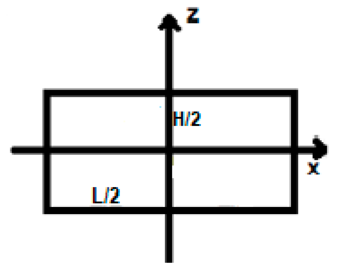
The second homogenization step assumes that stresses and strains are continuous across the strip interfaces. In this way, the effective or average stiffness tensor for the homogenized representative volume element (Figure 6) is represented by a 6x6 matrix and indicated in a contracted form by equation (66) [17]:
Where the upper index (**) indicates an effective or average quantity for the RVE.
Figure 5.
N strips of the first homogenization step of the representative volume element of the composite with ripples in the constituent layers [17].
Figure 5.
N strips of the first homogenization step of the representative volume element of the composite with ripples in the constituent layers [17].
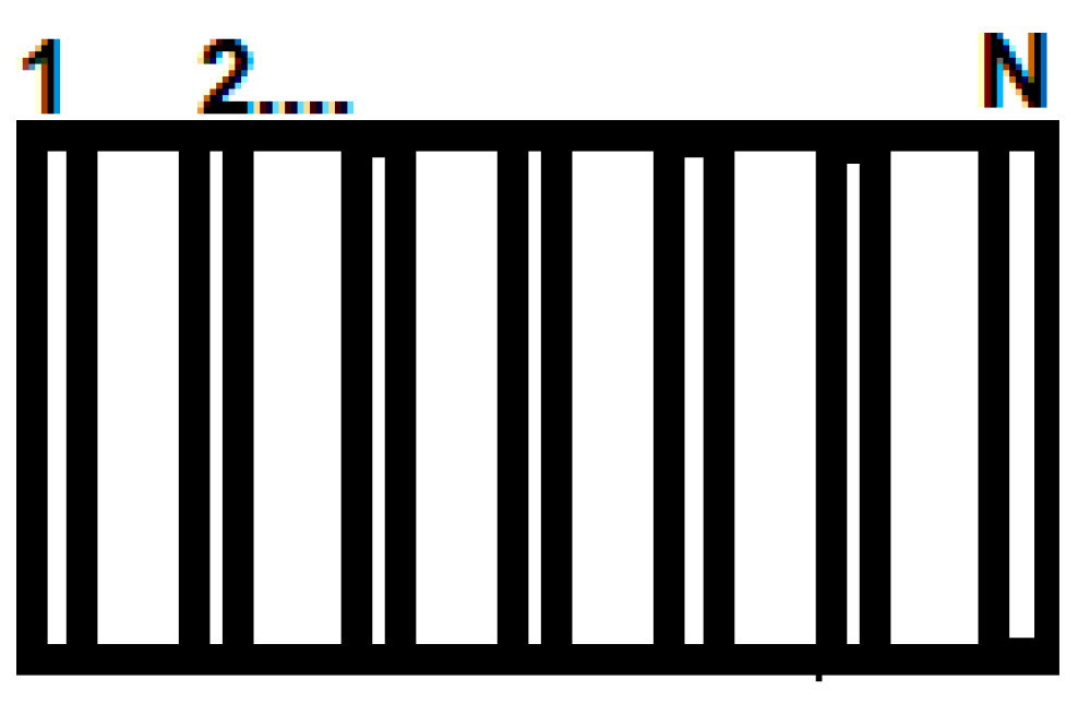
Figure 6.
Representative volume element homogenized according to the second step [17].
Figure 6.
Representative volume element homogenized according to the second step [17].
Na analysis combining the so-called micromechanical theory of failure with a cohesive zone model, in which a criterion for the initiation of interlaminar failures is established is the research proposal [18]. According to the authors of this work, to better understand the theory used in this study it is necessary to know its basic hypotheses, which are [18]:
- The fibers are assumed to be linear elastic, transversely isotropic and with uniform distribution.
- The matrix is considered linear elastic, isotropic and without voids.
- Every micro strain/stress component at any fiber or matrix point is linearly dependent on macro strains/stresses and on the temperature increment.
Where, is the micro stress at point i (has six stress components), is the macro stress in the periodic unit cell representative of the composite (has six stress components), is the amplification factor of the mechanical stress at point i (6x6 matrix ), is the thermal stress amplification factor at point i (6x1 matrix) [18].
Regarding the failure criteria used for fiber and matrix, the researchers in [18] emphasize that fibers are the main components of mechanical strength of laminated polymer composites and that damage to them is the primary indicator for the failure of the material when subjected to longitudinal tension and compression stresses. When longitudinal tension occurs, the stress componente of each critical point in the fiber is adopted as a parameter to evaluate whether or not the reinforcing element failure, such as:
And for the compression criterion, it has:
In which, it is analogous to equation (56) for fibers, and are the critical values of and for when fiber failures occur under tensile and compressive loads [18].
In continuity, the model for the progressive decrease in the effective compliance tensor as damage to the composite increases and a criterion for the strength to delamination of the material are stand out, they are also addressed in the researches [18,19]. In the first case, from the expression of the strain energy density for the damaged composite, equation (70), it can be written as:
About the criterion for the initiation of delamination (cohesive zone model), it can be expressed as [19]:
In which, are the normal and shear stresses, respectively, associated with the respective delamination crack opening modes, while N, S and T are the respective strengths of the interfaces to each of the aforementioned modes. The parentheses “< >” indicate that under pure compression delamination does not begin [19].
For failure analysis in curved laminated composites subjected to bending, Andraju and Raju in [20] use micromechanical models to describe some intra-laminar (matrix failure) and inter-laminar (delamination) damages. According to the research, two models are used to analyze the initiation of failure in the composite matrix:
Where, is the parameter for matrix failure under tension when , is the tensile strength in the thickness/depth direction, are shear strengths of the laminate [20,21].
In equation (74), is the parameter for matrix failure also under tension, but when , it indicates the tensile strength in the direction transverse to the fibers and is the shear strength in-plane of the laminae [20,21].
Still in the study [20], the authors use an exponential model for the progressive evolution of damage expressed as follows:
Where is the characteristic length of the representative volume elemento (RVE) of the laminate and is the fracture energy corresponding to the failure of the matrix subjected to tension [20], thus:
It is the elastic stiffness tensor accounting for progressive damage , in which [20]:.; with other symmetric terms being null.
Therefore, the stress-strain relationship can be expressed conditionally as in equation (77) below [20]:
Where, is the stiffness tensor for the undamaged composite. Finally, the authors in [20] use the cohesive zone model in equation (72) as a criterion to evaluate the opening of delamination cracks considering the stresses for mode I (normal) and modes II and III (shear).
Micromechanical analyzes considering progressive damage in laminated composites have been explored in more recent research. As a final emphasis, Liu et al [22] develop a study analyzing progressive damage to compression of laminated composites with stress concentrations. The authors propose a subroutine element of the commercial software ABAQUS that is constituted using the third-order shear deformation theory in conjunction with a two-dimensional progressive damage model and micromechanical criteria for fiber and matrix failure analyses. In order to verify the validity of the modeling, compression tests on laminated composites with cavities were carried out and the failure load predicted by theoretical modeling differed only 6.1% from that presented in the experimental analysis [22].
An interesting study conducted by Hu et al [23] propose a peridynamic micromechanical model (PD models), thus, based on the non-local continuum mechanics to analyze damage mechanisms in laminated composites. According to these authors, mathematical modeling is efficient in comparison to experimental literature data in terms of predictions that take into account important micromechanical characteristics and the initiation of damage. In this way, it makes it possible to investigate both the effective elastic properties and progressive mechanisms of deterioration of the material with good accuracy.
More recently, Li et al [24] developed a work in which they propose a more computationally efficient peridynamic micromechanical model (PD models) to characterize the strain and progressive damage behaviors in a laminated composite modeled with a single ply of material points. At the end of the research, as described by the authors, the alternative peridynamic model actually appears to have lower computational cost than conventional modeling using non-local continuum mechanics.
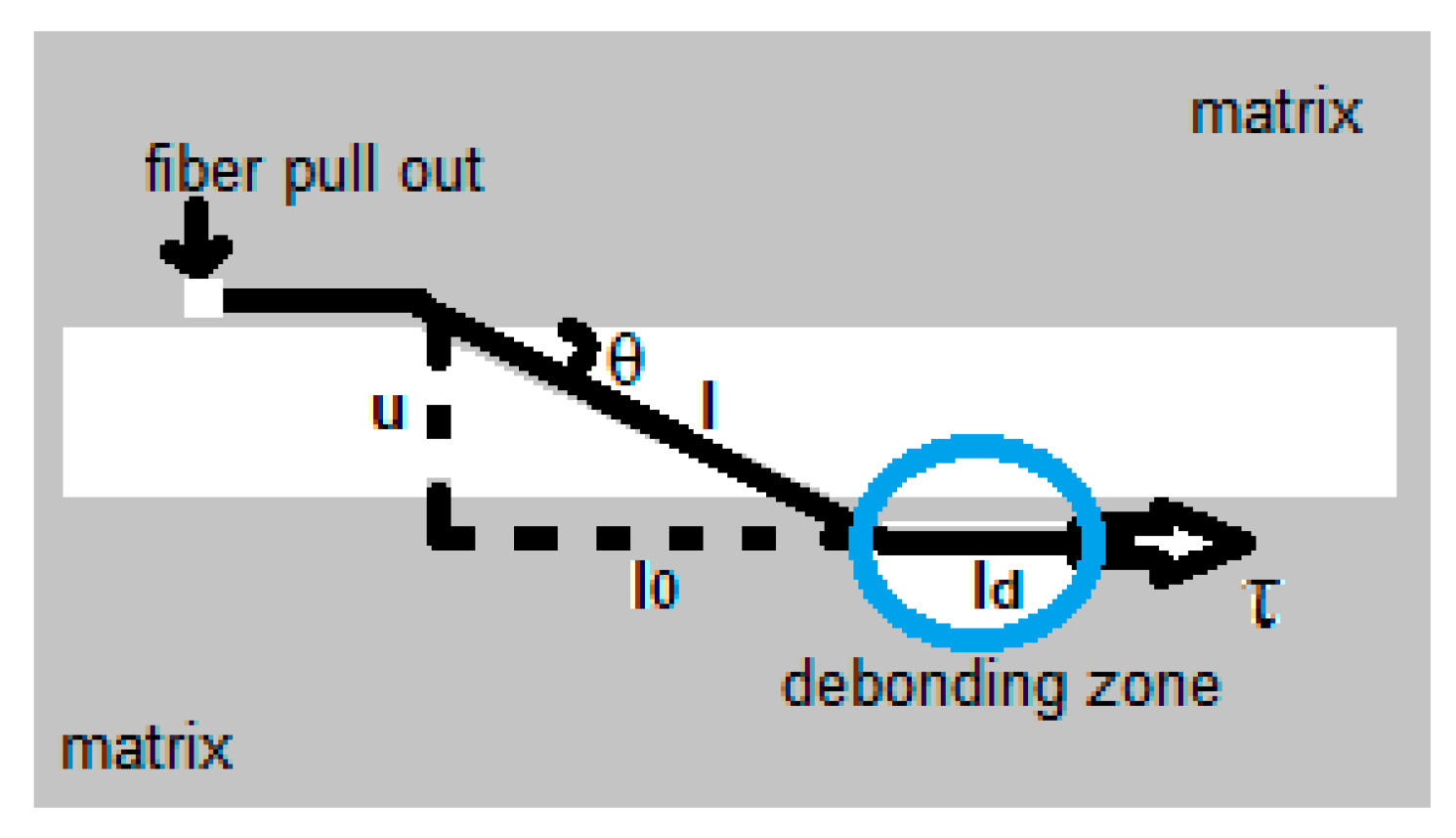
A study which presents micromechanical modeling for the fiber-matrix interface is developed by Lei et al [25]. As described by these researchers, the phenomenon of interfacial stress transfer is a relevant mechanical problem presented by fiber-reinforced composites. This behavior involves four successive stages, these are: when the interface is still intact and unites fiber and matrix, the process of detachment and separation between the two phases, the interface with fibers and matrix completely separated and the removal of fibers from within the matrix by tension loading (pull out). A model for the transfer of elastic stress can be developed through the balance of forces on the fiber and expressed as follows [25]:
Where, is the shear stress along the fiber immersed in the matrix given by the so-called Cox model, is the axial stress in the fiber and r is the fiber radius [25].
According to [25] the so-called Piggott model is used for the distribution of elastic axial stress in the fiber before interface separation, which is given by:
In (79), it is the stress acting on the fiber section outside the matrix, x is the distance to the fiber entry into the matrix, L is the effective stress transfer length, that is, it is the fiber length at which the axial stress will decay to zero, s is the fiber aspect ratio (L/r) and n is a parameter related to the geometry and material of the fiber and matrix [25].
Deriving the equation (79) using equation (78), it can be written [25]:
Which is the interfacial shear stress in the fiber section immersed in the matrix [25].
If continuous strains are applied, failure due to fiber fracture and failure due to detachment between fiber and matrix occur, respectively, when [25]:
With being the maximum interfacial shear stress (for which debonding between fiber and matrix occurs), and are the limit of fiber tensile strength and interfacial shear strength, respectively [25].
As the load increases in a pull out test, detachment initially occurs at the entry point of the fiber into the matrix (x = 0) and propagates along the interface, using the two previously mentioned stress models (Cox and Piggott), the authors of the research [25] also make demonstrations related to the transfer of shear stress due to friction in the detachment region between the continuos and dispersed phases.
Well, phenomena associated with delamination such as fiber bridging (Figure 7) can also be modeled by micromechanical analyses. According to Daneshjoo et al [26], the main micromechanisms involved in this phenomenon are three:
- Fragmentation of the matrix (Matrix spalling): Before fiber bridging occurs, the fibers are peeled-off from the matrix due to the opening of delamination cracks. After fiber bridging, the ends of the fiber section peeled from within the matrix continue to be inserted into the matrix and, under new loads, these ends also tend to leave the matrix, however, the continous phase begins to fragment due to the stress concentration generated by the phenomenon of fiber bridging prevail.
- Detachment of fibers (Fiber pull-out): Weak unions with detachments between fiber and matrix contribute to the loads being sufficient to remove the fibers from within the matrix. Then, after fiber bridging, the detachment conditions between the composite phases are favorable to fiber pull out.
- Fiber fracture: Under combined flexural and axial loads, fibers that have undergone the fiber bridging phenomenon tend to break.
The practical effects of fiber bridging end up being useful, given that they improve the fracture toughness of the laminate, in other words, the material becomes more resistant to the crack propagations. Micromechanical models for calculating the absorption energy in the fiber bridging zone, involving each of the three failure micromechanisms cited above, can be analyzed from [26], however, Mirsayar in [27] works on the micromechanical modeling of fiber bridging in a more detailed.
Figure 7.
Representation of a fiber bridging phenomenon in delamination crack in the composite material [27].
Figure 7.
Representation of a fiber bridging phenomenon in delamination crack in the composite material [27].
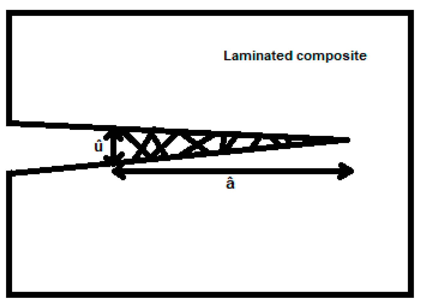
In research that uses a criterion based on the stress/energy combination for mixed modes of fracture in laminated composites, taking into account the micromechanical analysis of the fiber bridging [27], the author develops the following approach to this phenomenon:
Where, it is defined as the fiber bridging tenacity, it is the strength to the opening u of the crack that is developed along the so-called fiber bridging length â (see Figure 7), it is defined as the crack closure pressure and û is the opening at the end of the fiber bridging zone. The number of fibers involved in the bridging mechanism is a function of u, therefore, considering this fact, the crack closing pressure can be expressed by [27]:
In which, is the force per unit of fibers and is the number of fibers per unit area. Using Weibull statistical analysis, can be given by [27]:
Where m is the Weibull modulus, is considered the crack opening displacement, below which the number of fiber failures becomes negligible, is the crack opening displacement corresponding to the maximum closure pressure, is the stress level in which 63.2% of the fibers along the length fail, is the average maximum bending stress at the root of the fibers that were peeled, l is the bridging span and consists of a correction factor that is dimensionless [27].
The calculations of p(u) and f(u) must be done considering two steps. In an initial phase and in a steady state, considering that the phenomenon governing micromechanism and the evolution of f(u) correspond to each phase [27]. In the initial phase, after the fibers are peeled from the matrix and before the tensile stress acts on them due to the opening of the crack, the beam behavior is predominant over these reinforcement elements that were released from the layers of the laminated composite [27]. Then, the strength to crack opening is determined from the beam theory, as expressed by equation below [27]:
According to the displacement u of the crack opening increases, a significant normal tensile stress σ(u) is developed in the fiber that has been peeled (see Figure 8) [27]. By equilibrium condition, it is shown that the tensile stress due to the resistive shear τ and the debonding toughness of the fiber/matrix interface in a fiber of radius r can be expressed by [27]:
For θ << 1 rad, the total closure pressure is given by [27]:
Therefore, the mathematical model for toughness to the fiber bridging phenomenon is determined as follows [27]:
In which, during the initial phase (u <) only the non-exponential term is considered. So, it is noted here that as u increase, the fiber bridging thoghness also increases in this initial phase.
Experimental studies indicate that there is a limit to the integrity of the matrix in relation to the increase of the crack opening due to delamination [27]. The matrix begins to spall in the steady state and a micromechanical model relating fracture toughness to the maximum normal component of the force exerted by the fiber is indicated in equation (90), where is the average length of the crack that is parallel to the fiber in the which acts [27].
Figure 9.
Action of the maximum normal component exerted by the fiber on the matrix and the average length of the crack that fragments the matrix [27].
Figure 9.
Action of the maximum normal component exerted by the fiber on the matrix and the average length of the crack that fragments the matrix [27].
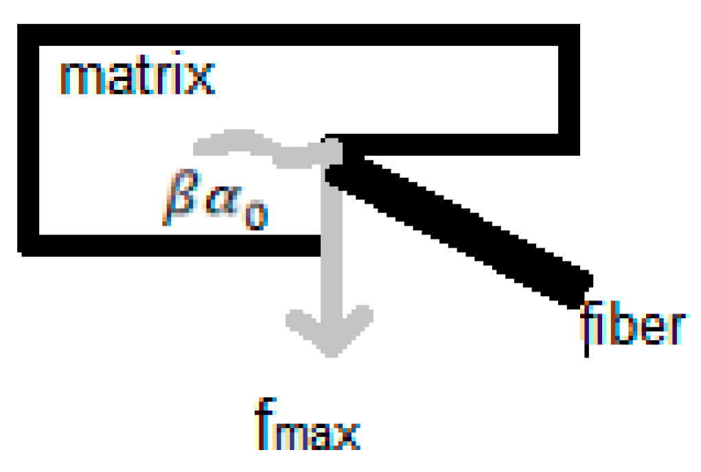
Therefore, associating equations (88) and (90), the maximum force generated on the matrix by flexion and traction of the fiber can be described as [27]:
From the equation (91) it is possible to determine the maximum displacement for opening of the crack before the matrix spalls, . Therefore, the fiber bridging toughness for the steady-state phase is determined by equation (92) [27]:
Can be observed from the equation (92) by this review that as u e l increases (l > u), considering that spalling of the matrix occurs for this stage, the toughness to the fiber bridging phenomenon during the steady state tends to zero.
Closing the analysis about the Mirsayar’s research [27], stands out the modeling of the stress field near the tip of an existing crack in an orthotropic laminated composite:
Where, are the components of the stress tensor in a rectangular coordinate system defined along the principal directions of the orthotropic material, are the stress intensity factors for modes I and II, respectively, are terms defined by [27]:
And the parameters are the pair of complex conjugate roots of the characteristic equation (95) [27]:
Where are the components of the elastic compliance tensor for the orthotropic composite [27].
A dynamic constitutive micromechanical model is suggested by Seyedalikhani et al [28] to predict mechanical behaviors as functions of strain rate in a epoxy matrix laminated composite. According to these authors, the generalized constitutive model for the polymer matrix phase dependent on the strain rate must encompass three aspects. The first one refers to the elastic behavior of polymers when subjected to normal and shear stresses, secondly, the inelastic behavior of polymers, which is prescribed based on the Johnson-Cook constitutive model and finally, a model to predict the strength limit of the polymer [28].
Regarding the elastic behavior of the polymer matrix, the following modeling is presented in study [28]:
In which, and are scaling constants of the material, , with and the applied and reference strain rates, respectively, and is the theoretical dynamic elastic modulus [28].
The modified Johnson-Cook ’s constitutive model, equation (97), is used to model the inelastic strains presented by the polymer matrix [28]:
Where, and are the plastic stress and strain equivalent to the inelastic phenomenon occurring in polymers, the constants involved are unknowns to be determined in mechanical tests with different strain rates [28].
To the strength of polymer matrix as a function of the strain rate in the polymer, the mathematical model can be described as the equation (98) [28]:
Where, is the ultimate tensile strength and are constants of the material [28].
With regard to the tensile strength of the glass fibers also as a function of the strain rate, in [28], the model is determined as follows:
In equation (99), is the ultimate tensile strength of a unidirectional composite at the strain rate shared by the fibers and and are material constants to be determined experimentally [28].
With meaningful highlight, the work [28] describes the theory of plasticity at the micromechanical level. According to the authors, most polymer composites reinforced by fibers unidirectionally present relevant inelastic strains before failing under in-plane shear and, in some situations, when subjected to transverse tensile loads too. The following model shows the relationship between the stress increments in the fiber and in the matrix for a unidirectional composite [28]:
Where, is the bridging tensor whose physical meaning has already been described in the previous section (2.1) of this research.
Still within this non-linear modeling, the elastic and elasto-plastic compliance tensor of the matrix phase is indicated by [28]:
Where, and the octahedral shear stress and the uniaxial yield strength of the matrix phase, respectively, are the components of the elastic compliance tensor and are the components of the plastic compliance tensor given by the matrix equation below [28]:
Where, are the components of the deviator stress tensor and is the octahedral shear stress, ,where and are the respective moduli of elasticity and the equivalent of the strain hardening for the matrix [28].
With k = 0,1,2... as the counter that indicates the respective loading step for which the stress and strain fields are calculated iteratively.
A synthesis about the study [28] ends by standing out two topics of the modeling proposed by the researchers. The first of them is about the sharing of the strain rate in matrix and fibers for a unidirectional composite, which is mathematically modeled based on the rule of mixture as follows:
In which and are the strain rates shared by the reinforcement and matrix phases, respectively, in relation to the total strain rate ( for the unidirectional composite [28].
The second topic would be the descriptions of dynamic progressive failure criteria in laminated composites, which can be expressed as follows [28]:
The equation (107) is the failure criterion due to dynamic tensile loading on the fibers, where are: the normal tensile stress, the tensile strength, the in-plane shear stress and the in-plane shear strength, respectively [28].
For dynamic compression loading, can be written [28]:
With being the compressive strength [28].
In equation (109), and represent the tensile stress transverse to the fibers and their respective strength and in equation (110) is the compressive strength limit. It is worth mentioning that tensile and compression failure modes in the fibers are catastrophic, in which the composite completely loses its ability to support loads, while the so-called non-catastrophic failures (material retains partially the capacity to support loads) caused by other modes are also discussed briefly in [28].
Jarali et al [29] developed micromechanical modeling aimed at three-phase composites with shape memory polymer matrices. In this research, the authors extend Eshelby’s method by considering two distinct inclusions immersed separately in a heterogeneous shape memory matrix. The effective average elastic modulus assuming dual inclusion modeling for the analyzed composite was given by:
Equation (111) is obtained by the authors in [29] as a new dilute distribution relationship based on Eshelby’s theory, which contemplates elastic properties of the composite when the representative volume element has two inclusions in a heterogeneous matrix. In that equation, is the elastic modulus of the shape memory polyme matrix, I is the identity tensor, , are the volume fractions of the fiber and carbon nanotube inclusions, the respective elastic moduli and the fourth order Eshelby tensors also for fiber and nanotube. With the novel proposal summarized above, Jarali et al [29] obtain a satisfactory comparison in relation to fundamental models such as the rule of mixture, for example, showing the consistency of the suggested model.
A novel micromechanical modeling to estimate effective properties in unidirectional composites reinforced by circular cross-section fibers was developedby Vignoli et al [30]. Based on the rule of mixture, the following equations were obtained:
In which the parameters, , with being the longitudinal and transverse modulus of elasticity of the fibers, the volumetric fraction of fibers, the modulus of elasticity of the matrix (considered homogeneous and isotropic), in-plane Poisson’s ratio of the fibers, Poisson’s ratio of the matrix, the in-plane and out-plane shear moduli of lamina and the matrix shear modulus, respectively [30].
The researchers in [30], through a comparative analysis with other fundamental models, were able to conclude that the model called VSPKc showed the best results based on experimental data from literature and finite element analysis.
The technique known as asymptotic homogenization and the unit cell concept for multiphase materials are used in [31] in order to develop a general micro and nanomechanical model for an anisotropic smart nanocomposite with quantum dots embedded and piezoelectrically active constituents. In summary, the concept of unit cell is used for the microstructure of the material and a power series expansion of the variables ui(x,y) (displacement), σi(x,y) (stress), Di(x,y ) (electrical displacement), φi(x,y).
The effective properties of the multiphase material are determined from the set of equations (117)-(122) and, according to the authors of the study [31], the analytical results present good agreement with those obtained numerically with the aid of the finite element software ABAQUS.
On what:
In which, are the tensors of elastic, piezoelectric and dielectric permittivity coefficients, in addition, y is the variable that accounts for the periodicity of the composite’s microstructure and are terms associated with the rate of variation of the aforementioned tensors, as can be seen in [31] .
Finally, this literature review must stands out an interesting probabilistic micromechanical modeling carried out by Naskar et al [32], where a stochastic concept about representative volume element (RVE) is proposed. The authors of that research use a structural domain divided into N micro subdomains in which the material properties are presented randomly in space, in other words, the fundamental volumetric unit is considered within a stochastic context instead of the homogenization proposed by a conventional representative volume element. Hence, effects of the random spatial distribution of mechanical properties for different regions of a structure can be accounted in the modeling [32].
3. Final Remarks
Notably, micromechanical analyses have had the opportunity to deal with increasingly sophisticated modeling from the point of view of mathematics and appropriated applied sciences. However, traditional or reformulated elementary methods and approaches are still widely used in studies on the mechanics of composites involving their constituent phases, in other words, these fundamental models have also served as the basis for advances made in the area and have not fallen into disuse with the emergence of more elaborate proposals.
In fact, for all the content analyzed in this systematic review of literature, the micromechanics of polymer laminated composites constitutes a branch of solid mechanics that is completely open and is undergoing frank and broad expansion with regard to the development and consolidation of new knowledges within engineering applied sciences, thus, offering the opportunity for several physical and mathematical modelings to be proposed, duly evaluated and improved with the aim of predicting effective properties to describing progressive damage mechanisms in these multiphase materials with greater accuracy.
Exposed all this context, a trend analysis is constructed for future work that may come in the line of increasingly developing numerical models in order to optimize computational costs and with approaches that are able of considering strain fields influenced by the neighborhood, in other words, those are based on non-local theories and methods, for example, to multiphase laminates that also feature nanoparticle reinforcement.
In addition to the perspectives described previously, novel stochastic micromechanical approaches are expected, i. e., modeling that assumes that random character of the composite’s properties in more realistic representative volumes and, finally, studies considering characteristics of fibers, matrices and interfaces that can model the geometric path described by the tip a delamination crack through the existing duality with the stress wave fronts that advance through the material after the dynamic loading, for example, it also is a part of projections for future analyses. In case of a satisfactory approximation in relation to experimental observations, this last type of modeling mentioned could contribute significantly to the design of polymer matrix laminates with greater interlaminar strengths.
References
- Ahani, A.; Ahani, E. An overview for materials and design methods used for enhancement of laminated glass. Hybrid Adv. 2023, 3. [Google Scholar] [CrossRef]
- EL Kinani, K.; Meunier, S.; Vido, L.; Le Ballois, S. Interdisciplinary analysis of wind energy - a focus on France. Sustain. Energy Technol. Assessments 2023, 55. [Google Scholar] [CrossRef]
- Jones, R.M. Mechanics of Composite Materials, 2nd ed.; Taylor and Francis Publisher, 1999.
- Aboudi, J.; Arnold, S.; Bednarcyk, B. Micromechanics of Composite Materials; Elsevier: Amsterdam, The Netherlands, 2013. [Google Scholar]
- Kundalwal, S.I. Review on micromechanics of nano- and micro-fiber reinforced composites. Polym. Compos. 2018, 39, 4243–4274. [Google Scholar] [CrossRef]
- Kumar, P.; Chandra, R.; Singh, S.P. Interphase Effect on Fiber-Reinforced Polymer Composites. Compos. Interfaces 2010, 17, 15–35. [Google Scholar] [CrossRef]
- Basu, S.; Waas, A.M.; Ambur, D.R. Prediction of progressive failure in multidirectional composite laminated panels. Int. J. Solids Struct. 2007, 44, 2648–2676. [Google Scholar] [CrossRef]
- Vasiliev, V.; Morozov, E. Advanced Mechanics of Composite Materials and Structural Elements, 3rd ed.Elsevier: Amsterdam, The Netherlands, 2013. [Google Scholar]
- Wang, Y.; Huang, Z. Analytical Micromechanics Models for Elastoplastic Behavior of Long Fibrous Composites: A Critical Review and Comparative Study. Materials 2018, 11, 1919. [Google Scholar] [CrossRef] [PubMed]
- Ivančević, D.; Smojver, I. Micromechanical damage modelling using a two-scale method for laminated composite structures. Compos. Struct. 2014, 108, 223–233. [Google Scholar] [CrossRef]
- Meshi, I.; Levi-Sasson, A.; Breiman, U.; Haj-Ali, R. The parametric HFGMC micromechanical model for soft UHMWPE laminated composites. Mech. Mater. 2019, 141, 103223. [Google Scholar] [CrossRef]
- Cui, W.; Zhu, R. A Review on Tough Soft Composites at Different Length Scales. Textiles 2021, 1, 513–533. [Google Scholar] [CrossRef]
- Pineda, E.J.; Bednarcyk, B.A.; Arnold, S.M. Validated progressive damage analysis of simple polymer matrix composite laminates exhibiting matrix microdamage: Comparing macromechanics and micromechanics. Compos. Sci. Technol. 2016, 133, 184–191. [Google Scholar] [CrossRef]
- Ivančević, D.; Smojver, I. Explicit multiscale modelling of impact damage on laminated composites – Part I: Validation of the micromechanical model. Compos. Struct. 2016, 145, 248–258. [Google Scholar] [CrossRef]
- Massarwa, E.; Aboudi, J.; Haj-Ali, R. A multiscale progressive damage analysis for laminated composite structures using the parametric HFGMC micromechanics. Compos. Struct. 2018, 188, 159–172. [Google Scholar] [CrossRef]
- Patel, D.K.; Waas, A.M. Multiscale analysis of notched fiber reinforced laminates. Compos. Part B: Eng. 2019, 173, 106986. [Google Scholar] [CrossRef]
- Takeda, T. Micromechanics model for three-dimensional effective elastic properties of composite laminates with ply wrinkles. Compos. Struct. 2017, 189, 419–427. [Google Scholar] [CrossRef]
- Lou, X.; Cai, H.; Yu, P.; Jiao, F.; Han, X. Failure analysis of composite laminate under low-velocity impact based on micromechanics of failure. Compos. Struct. 2017, 163, 238–247. [Google Scholar] [CrossRef]
- McCarthy, C.; O’Higgins, R.; Frizzell, R. A cubic spline implementation of non-linear shear behavior in three-dimensional progressive damage models for composite laminates. Compos. Struct. 2010, 92, 173–181. [Google Scholar] [CrossRef]
- Andraju, L.B.; Raju, G. Continuum and cohesive zone damage models to study intra/inter-laminar failure of curved composite laminates under four-point bending. Compos. Struct. 2020, 253, 112768. [Google Scholar] [CrossRef]
- Yang, Y.; Liu, X.; Wang, Y.-Q.; Gao, H.; Li, R.; Bao, Y. A progressive damage model for predicting damage evolution of laminated composites subjected to three-point bending. Compos. Sci. Technol. 2017, 151, 85–93. [Google Scholar] [CrossRef]
- Liu, Z.; Yan, L.; Wu, Z.; Zhou, J.; Wei, H.; Zhang, S.; Ren, X. Progressive damage analysis and experiments of open-hole composite laminates subjected to compression loads. Eng. Fail. Anal. 2023, 151. [Google Scholar] [CrossRef]
- Hu, Y.; Wang, J.; Madenci, E.; Mu, Z.; Yu, Y. Peridynamic micromechanical model for damage mechanisms in composites. Compos. Struct. 2022, 301. [Google Scholar] [CrossRef]
- Li, F.; Yang, X.; Gao, W.; Liu, W. A single-layer Peridynamic model for failure analysis of composite laminates. Mater. Today Commun. 2023, 37. [Google Scholar] [CrossRef]
- Lei, Z.; Li, X.; Qin, F.; Qiu, W. Interfacial Micromechanics in Fibrous Composites: Design, Evaluation, and Models. Sci. World J. 2014, 2014, 1–9. [Google Scholar] [CrossRef] [PubMed]
- Daneshjoo, Z.; Shokrieh, M.; Fakoor, M. A micromechanical model for prediction of mixed mode I/II delamination of laminated composites considering fiber bridging effects. Theor. Appl. Fract. Mech. 2018, 94, 46–56. [Google Scholar] [CrossRef]
- Mirsayar, M.M. A combined stress/energy-based criterion for mixed-mode fracture of laminated composites considering fiber bridging micromechanics. Int. J. Mech. Sci. 2021, 197. [Google Scholar] [CrossRef]
- Seyedalikhani, S.; Shokrieh, M.; Shamaei-Kashani, A. A novel dynamic constitutive micromechanical model to predict the strain rate dependent mechanical behavior of glass/epoxy laminated composites. Polym. Test. 2019, 82, 106292. [Google Scholar] [CrossRef]
- Jarali, C.S.; Madhusudan, M.; Vidyashankar, S.; Raja, S. A new micromechanics approach to the application of Eshelby’s equivalent inclusion method in three phase composites with shape memory polymer matrix. Compos. Part B Eng. 2018, 152, 17–30. [Google Scholar] [CrossRef]
- Vignoli, L.L.; Savi, M.A.; Pacheco, P.M.C.L.; Kalamkarov, A.L. A Novel Micromechanical Model Based on the Rule of Mixtures to Estimate Effective Elastic Properties of Circular Fiber Composites. Appl. Compos. Mater. 2022, 29, 1715–1731. [Google Scholar] [CrossRef]
- Alam, A.; Saha, G.C.; Kalamkarov, A.L. Micromechanical analysis of quantum dot-embedded smart nanocomposite materials. Compos. Part C Open Access 2020, 3, 100062. [Google Scholar] [CrossRef]
- Naskar, S.; Mukhopadhyay, T.; Sriramula, S. Probabilistic micromechanical spatial variability quantification in laminated composites. Compos. Part B Eng. 2018, 151, 291–325. [Google Scholar] [CrossRef]
- Shokrieh, M.M.; Kashani, A.R.S.; Mosalmani, R. A dynamic constitutive-micromechanical model to predict the strain rate-dependent mechanical behavior of carbon nanofiber/epoxy nanocomposites. Iran. Polym. J. 2016, 25, 487–501. [Google Scholar] [CrossRef]
- ergmann, T., Heimbs, S. Progressive bearing failure of composites for crash energy absorption, Dynamic Response and Failure of Composite Materials and Structures; Woodhead Publishing, 2017; pp. 299–334.
- Khan, R. Fiber bridging in composite laminates: A literature review. Compos. Struct. 2019, 229, 111418. [Google Scholar] [CrossRef]
- Godara, S.; Mahato, P. A study on micromechanical methods for the analysis of composite materials. Mater. Today: Proc. 2020, 26, 1096–1098. [Google Scholar] [CrossRef]
- Salerno, G. Numerical analysis of delamination in carbon-epoxy composite materials. Technology. Metal. Mater. Miner. São Paulo. 2013, 10, 153–161. [Google Scholar] [CrossRef]
- Farrokhabadi, A.; Hosseini-Toudeshky, H.; Mohammadi, B. A generalized micromechanical approach for the analysis of transverse crack and induced delamination in composite laminates. Compos. Struct. 2011, 93, 443–455. [Google Scholar] [CrossRef]
- Tsukamoto, H. A mean-field micromechanical approach to design of multiphase composite laminates. Mater. Sci. Eng. A 2011, 528, 3232–3242. [Google Scholar] [CrossRef]
- Pyo, S.; Lee, H. Micromechanics-based elastic-damage analysis of laminated composite structures. Int. J. Solids Struct. 2009, 46, 3138–3149. [Google Scholar] [CrossRef]
- Mishnaevsky, L., Jr.; Brøndsted, P. Micromechanical modeling of damage and fracture of unidirectional fiber reinforced composites: A review. Comput. Mater. Sci. 2009, 44, 1351–1359. [Google Scholar] [CrossRef]
- Drago, A.; Pindera, M.-J. Micro-macromechanical analysis of heterogeneous materials: Macroscopically homogeneous vs periodic microstructures. Compos. Sci. Technol. 2007, 67, 1243–1263. [Google Scholar] [CrossRef]
- Garnich, M.R.; Karami, G. Finite Element Micromechanics for Stiffness and Strength of Wavy Fiber Composites. J. Compos. Mater. 2004, 38, 273–292. [Google Scholar] [CrossRef]
- Jacobs, E., Verpoest, I., Varna, J. On the use and limitations of concentric cylinder models for polymer matrix composites. ICCM-12 Europe. 12th International Conference on Composite Materials. Palais Des Congres, Paris. 1999.
- Williams, T. Pindera, MJ. Multiple Concentric Cylinder Model (MCCM) User’s Guide. University of Virginia and NASA. 1994.
- Stucu, M. A recursive concentric cylinder model for composites containing coated fibers. Int. J. Solids Struct. 1992, 29, 197–213. [Google Scholar] [CrossRef]
- Benveniste, Y. A new approach to the application of Mori-Tanaka’s theory in composite materials. Mech. Mater. 1987, 6, 147–157. [Google Scholar] [CrossRef]
- Neto, F.L.; Pardini, L.C. Structural composites - science and technology. 2nd revised and expanded edition. ed. Blucher. 2016.
- Sun, C.T.; Chen, J.L. A micromechanical model for plastic behavior of fibrous composites. Compos. Sci. Technol. 1991, 40, 115–129. [Google Scholar] [CrossRef]
- Vignoli, L.; Savi, M.A.; Pacheco, P.M.; Kalamkarov, A.L. Micromechanical analysis of transversal strength of composite laminae. Compos. Struct. 2020, 250, 112546. [Google Scholar] [CrossRef]
- Van Paepegem, W. Multi-Scale Continuum Mechanics Modeling of Fiber-Reinforced Polymer Composites. In Woodhead Publishing Series in Composites Science and Engineering; Woodhead Publishing, 2021.
- Shaofan, L.; Wang, G. Introduction to Micromechanics and Nanomechanics, 2nd ed.; World Scientific Publishing Co. Pte., 2018.
- Aboudi, J.; Arnold, S.M.; Bednarcyk, B.A. Micromechanics of Composite Materials: A Generalized Multiscale Analysis Approach; Oxford OX5: Butterworth-Heinemann Ltd., 2012. [Google Scholar]
- Esmaeili, M.; Ansari, R.; Mottaghitalab VHaghi, A.K.; Xi, B.; Spinks, G.M.; GGWallace, G.G.; Minett, A.I. CNT/polymer nanocomposites: A detailed review on mathematical modeling and experimental case studies; CRC Press, 2014; p. 149.
- Sendeckyj, G.; Wang, S.; Johnson, W.S.; Stinchcomb, W.; Chamis, C. Mechanics of Composite Materials: Past, Present, and Future. J. Compos. Technol. Res. 1989, 11. [Google Scholar] [CrossRef]
- Esposito, L.; Pucillo, G.; Penta, F.; Rosiello, V. Micromechanical study and simulation of the interlaminar failure of a woven composite laminate. Procedia Struct. Integr. 2016, 2, 1870–1877. [Google Scholar] [CrossRef]
- Jha, N.K.; Kumar, S.; Tyagi, A.; Jha, D.K.; Jha, C.S. Finite element and micromechanical analysis of glass/epoxy laminated composite with different orientations. Mater. Today: Proc. 2020, 28, 1899–1903. [Google Scholar] [CrossRef]
- Mahapatra, T.R.; Panda, S.K. Nonlinear free vibration analysis of laminated composite spherical shell panel under elevated hygrothermal environment: A micromechanical approach. Aerosp. Sci. Technol. 2016, 49, 276–288. [Google Scholar] [CrossRef]
- Eshelby JD. The elastic field outside an ellipsoidal inclusion. Proc R Soc Lond Ser. A252. 561–9. 1959. [CrossRef]
- Naderi, M., Iyyer, N. Micromechanical analysis of damage mechanisms under tension of 0°–90° thin-ply composite laminates. Composite Structures. Volume 234. 2020. 111659. [CrossRef]
- Naskar, S.; Mukhopadhyay, T.; Sriramula, S.; Adhikari, S. Stochastic natural frequency analysis of damaged thin-walled laminated composite beams with uncertainty in micromechanical properties. Compos. Struct. 2017, 160, 312–334. [Google Scholar] [CrossRef]
- Benveniste, Y. A general interface model for a three-dimensional curved thin anisotropic interphase between two anisotropic media. J. Mech. Phys. Solids 2006, 54, 708–734. [Google Scholar] [CrossRef]
- Murakami, S. Continuum Damage Mechanics: A Continuum Mechanics Approach to the Analysis of Damage and Fracture; Springer, 2012.
- Reddy, J.N. Na Introduction to Continuum Mechanics; Cambridge University Press, 2007.
- Chamis, C.C.; Abdi, F.; Garg, M.; Minnetyan, L.; Baid, H.; Huang, D.; Housner, J.; Talagani, F. Micromechanics-based progressive failure analysis prediction for WWFE-III composite coupon test cases. J. Compos. Mater. 2013, 47, 2695–2712. [Google Scholar] [CrossRef]
- Benveniste, Y.; Miloh, T. Imperfect soft and stiff interfaces in two-dimensional elasticity. Mech. Mater. 2001, 33, 309–323. [Google Scholar] [CrossRef]
- Eshelby JD. The determination of the elastic field of an elipsoidal inclusion, and related problems. Proc R Soc Lond Ser. A241. 376–96. 1957. [CrossRef]
- Daniel, I.; Ishai, O. Engineering Mechanics of Composite Materials, 2nd ed.; Oxford University Press, 2008.
- Eshelby JD. The elastic field outside an ellipsoidal inclusion. Proc R Soc Lond Ser. A252. 561–9. 1959. [CrossRef]
- Mori, T.; Tanaka, K. Average stress in matrix and average elastic energy of materials with misfitting inclusions. Acta Met. 1973, 21, 571–574. [Google Scholar] [CrossRef]
- Wang, Y. and Huang, Z. A Review of Analytical Micromechanics Modelo n Composite Elastoplastic Behaviour. 11th International Simposium on Plasticity and Impact Mechanics. Procedia Engineering 173. 1283-1290 (2017). [CrossRef]
Figure 1.
Shear in fiber-reinforced composite and the respective longitudinal and transverse directions referenced by sub-indexes of the previous elastic constants [5].
Figure 1.
Shear in fiber-reinforced composite and the respective longitudinal and transverse directions referenced by sub-indexes of the previous elastic constants [5].
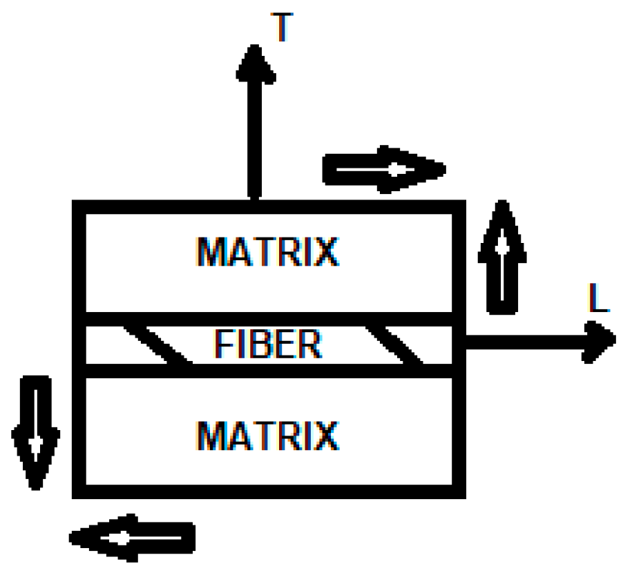
Figure 3.
An arrangement of cells and their subcells in a composite section with aligned fibers [5].
Figure 3.
An arrangement of cells and their subcells in a composite section with aligned fibers [5].
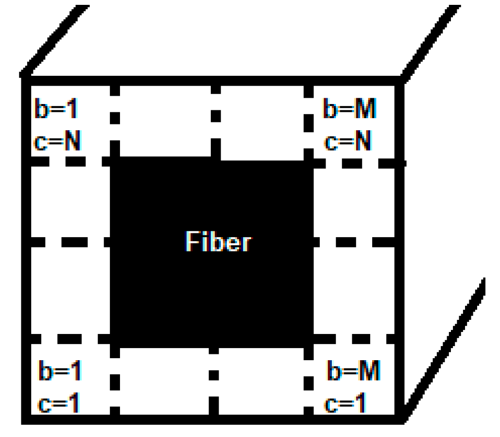
Figure 8.
Fiber bridging and respective variables of the micromechanical modeling of this phenomenon [27].
Figure 8.
Fiber bridging and respective variables of the micromechanical modeling of this phenomenon [27].
Disclaimer/Publisher’s Note: The statements, opinions and data contained in all publications are solely those of the individual author(s) and contributor(s) and not of MDPI and/or the editor(s). MDPI and/or the editor(s) disclaim responsibility for any injury to people or property resulting from any ideas, methods, instructions or products referred to in the content. |
© 2024 by the authors. Licensee MDPI, Basel, Switzerland. This article is an open access article distributed under the terms and conditions of the Creative Commons Attribution (CC BY) license (http://creativecommons.org/licenses/by/4.0/).
Copyright: This open access article is published under a Creative Commons CC BY 4.0 license, which permit the free download, distribution, and reuse, provided that the author and preprint are cited in any reuse.


