Submitted:
12 January 2024
Posted:
14 January 2024
You are already at the latest version
Abstract
Contactless charging is evolving fast in many domains and applications such as the electrical vehicles (EV). The principle consists of transferring energy between two systems without having any electrical connection between them. This power transfer can be realized by emitting a magnetic field for Inductive Power Transfer (IPT). In the automotive domain, the application of contactless charging to supply power to the vehicle while driving is one of the solutions envisaged to solve the limited autonomy range of EV and reduced its cost but the system must comply with existing standards (e.g., allocated frequency range and radiated electromagnetic emissions), as summarized in this paper.
Keywords:
Dynamic Inductive Power Transfer
; norms
; standards
; recommendations
1. Introduction
A technology for Electrical Vehicle (EV) charging that has gained popularity in the last ten years is Inductive Power Transfer (IPT). IPT can solve many mechanical constraints raised by sliding contact technologies. Power transfer is done wirelessly via magnetic induction as presented in the 1, with a schematic overview of a typical static1 IPT system.
Each building block used in Figure 1 can be defined as the following:
- LF Rectifier: Generates a DC source from a Low-Frequency AC grid.
- HF Inverter: Generates High-Frequency AC from DC.
- Compensation Network: Capacitors are used to compensate for the low magnetic coupling between the transmitter and receiver’s coil.
- HF Rectifier: Generates a DC source from a High-Frequency AC
- Tx & Rx Coils: Magnetically coupled inductors used as means to transfer power wirelessly
The most common form of IPT systems is static, but Dynamic2 IPT (DIPT) systems capable of charging vehicles while in motion are also feasible. One way to achieve DIPT could be done by multiplying the number of transmitter modules, as depicted in Figure 2. The transmitter with the highest magnetic coupling at the receiver level would be used for the power transfer.

Table 1.
Challenges facing DIPT systems.
| EV Detection | Communication Protocol | Initialization | Power Control | Sequencing Control | Termination Protocol |
|---|---|---|---|---|---|
| Vehicle Integration | Road Integration | Magnetic Radiation | EMC | Modularity | Interoperability |
| Efficiency | Thermal Management | Maintenance | Durability | Reliability | Foreign Object Detection |
| Payment Method | Business Model | Safety | Cost | LCA | Standardization |
Several project for automotive applications are in developments all around the world such as RPEV Project in California’s program for a power of 60 kW [1], or the OLEV Project – KAIST project with several generations and several power [2,3,4,5,6,7,8,9], or the Cooperative Research and Development Agreement (CRADA) [10,11,12], or the Electric Vehicle Roadway (EVR) research facility and test track [13] with several kind of vehicles [14]. They achieve for example over 87% overall efficiency (AC grid to vehicle’s battery) over an 18 cm airgap [15]. In Europe, PRIMOVE with Bombardier [16] or Intis [17,18,19,20,21,22,23,24] is able of transferring 30 kW (to an Artega electric sports car) and 60 kW (to an 18 m electric bus) over a 15 cm airgap at 30 kHz. Several other projects are in developments for exmple in Europe such the The FastInCharge [25,26], the eCo-FEV [27], the Fabric or Incit-EV [28,29]. An additional challenge for this solution is to validate all norms in order to be commercialized on the market and avoid any health problems. These norms are summarized in this paper.
Table 2.
Document type of the scientific publications.
| Number of publication | ||
|---|---|---|
| Document Type | Static IPT | Dynamic IPT |
| Conference Papers | 1146 | 200 |
| Articles | 952 | 215 |
| Books | 44 | 7 |
| Total | 2142 | 422 |
| 2564 | ||
2. Scientific Publication Trends
IPT systems have been known for a long time. However, interest in this field has increased considerably with momentum between 2012 and 2019. This can be seen in the scientific publication trend presented in Figure 3. The data presented have been collected via the Scopus database3 [30], whereas the document type of the publications is summarized in
Table 2.
The drop in years 2020 and 2021 is simply due to the global Corona epidemic. More information regarding the author’s affiliations can be found in Figure 4 and Figure 5 [31].
| Number of publication | ||
|---|---|---|
| Document Type | Static IPT | Dynamic IPT |
| Conference Papers | 1146 | 200 |
| Articles | 952 | 215 |
| Books | 44 | 7 |
| Total | 2142 | 422 |
| 2564 | ||
We can observe that the research in this are field is globally investigated all around the world with a high expertise in New-Zeland, in China, in America and in Europe at GeePs, Delft, Imperial college and Torino.
3. Inductive Power Transfer standards
This paper presents a review of the Inductive Power Transfer standards (SAE, IEC, ISO, GB/T…), including an extensive revision regarding magnetic field exposure limits. Moreover, the latest data concerning the scientific publication on IPT systems are sorted and presented, showing the major academic institutions contributing to this field.
Since DIPT solutions require substantial investments in public and shared roads, standardization is indispensable for the widespread development of this technology. Before presenting this standard review, it is essential to clarify the related technical terms within the standardization field. Many terms are mistakenly interchanged, such as: Standards, Guidelines, Technical Specification, Technical Report, Publicly Available Specification… In brief, an International Standard is a rigorous set of rules, practices, and definitions aimed at achieving the optimum degree of order in a given context. On the other hand, Guidelines are simply recommendations with a more significant level of flexibility regarding implementation and could turn into Standards over time. Further details are present in [32].
It is important to note that neither an International Standard nor a Guideline possesses the power of law. Therefore, they are not legally binding. However, they could be referred to by a regulatory body (that enforces laws) and could almost be unavoidable in some instances. In the case of the European Union (EU), directives have an obligatory nature and often reference Standards/Guidelines. These referenced Standards are then called Harmonized Standards when published for example into the official European journal (GUCE). These Harmonized Standards are not obligatory but present a guaranteed path to presume the conformity of a product with an obligatory directive [33]. Moreover, the EU can publish a recommendation with a non-binding nature for a specific topic. As a consequence, each EU member state is free to transpose the EU recommendation into binding national legislation or not.
3.1. Static IPT
3.1.1. SAE J2954
One of the most known and well-accepted International Standards regarding static Wireless Power Transfer (WPT) for light-duty plug-in EVs is the SAE J2954/1 [34]. It is the only standard covering all aspects of the WPT system in a single document. Moreover, the latest revision of this standard has been harmonized with numerous standard organizations (especially ISO and IEC) while integrating feedback from government agencies (US DOE, FCC, and FDA). All three power levels described in the SAE J2954/1 are below 11.1 kVA and only adequate for light-duty EVs. The proposed 3 power levels (below 3 kW, from 3 to 7 kW, and from 7 to 11 kW) are chosen based on the levels defined for conductive AC charging with slight variations (SAE J1772). Harmonizing power levels allows vehicles with wireless charging capabilities to be charged by SAE J1772 plug-in chargers. A complementary document, SAE J2954/2, is currently in the development phase and will be dedicated to static WPT for high-power heavy-duty EVs. It should include power levels from 22 kW to at least 200 kW with lower operating frequencies envisaged to balance out the switching losses versus resistive and magnetic losses at such high-power levels. It is to be noted that all published standards only consider above-ground mounting for the ground assembly. Moreover, the communications channel should comply with SAE J2836/6, J2847/6, and J2931/6.
There are several safety requirements mentioned in the Standard. In the next paragraph, we will detail the radiated emissions concerning human exposure. In addition, this Standard gives suggested guidelines for Live Object Protection (LOP) functionality to be integrated into the system. This requirement is only described by functional, performance, and safety requirements and leaves the technical implementation free for the system designers. Another concern is heating foreign metallic objects present in the vicinity of the system. This is due to the presence of a varying magnetic flux that could potentially heat metallic objects, especially with large surfaces. These standard dictates that the system must be able to perform metallic Foreign Object Detection (FOD) that could either rise in temperature or even ignite that would cause an unsafe condition at any time during charging operation and to take appropriate action by alerting the operator or powering down if needed. Two test scenarios are envisaged: object placed before power transfer or during power transfer. Some of the sample objects mentioned:
- Avoid temperature rise due to: paper clip (standard size 2.86 cm), staple (Ferromagnetic steel, rectangular wire 0.5 x 0.7 mm, 6 x 12.8 mm), coins (2 €), beverage can, nail, steel or aluminum sheet (5 x 7.5 cm)
- Avoid ignition due to paper stack with paper clip or staple (e.g., 5 A4 sheets with standard size paper clip or staple
3.1.2. IEC 61980
Another International Standard for WPT systems is the IEC 61980. It is devised into 3 parts. Part 1 presents the general requirements and is published as International Standard. Part 2 deals with specific requirements for communication between the EV and infrastructure and is published as a Technical Specification. Part 3 deals with specific requirements for the magnetic field wireless power transfer systems and is also published as a Technical Specification. Both parts 2 and 3 are expected to have an update by the end of 2022 and be transformed into International Standards. A new technical comity (TC69) has been attributed to work on high power WPT (H-WPT). The result of this work will be published as part 4 of the IEC 61980.
3.1.3. ISO 19363
The ISO 19363 is a recent International Standard (published in 2020) after superseding a publically available specification. EV devices that fulfill the requirements in this document are intended to operate with supply devices that fulfill the magnetic field WPT-related requirements in the IEC 61980 series.
3.1.4. GB/T 38775
Another standardization body that published a standard for WPT systems is the GB. It is the National Standards of the People's Republic of China. In 2020, the GB issued the GB/T 38775 relative to WPT. It composes of 5 separate documents specifying respectively: the general requirements, classification, interoperability requirements, communication requirements, and environmental testing. Only the environmental testing document introduces a slight deviation from the other standards.
3.1.5. ISO 15118-20
The ISO 15118-20 has been recently published (04/2022) and specifies the communication between the EV and the electric vehicle supply equipment. In this document, wireless communication requirements are defined for both wireless and conductive charging as well as communication requirements for automatic connection devices. Moreover, this document defines the communication messages and sequence requirements for bidirectional power transfer.
3.1.6. Future Work
Flush mounting and below-ground mounting are mentioned as future work (SAE and GB). Moreover, bidirectional power flow is currently being considered by SAE, GB, and ISO for future publications.
3.2. Dynamic IPT
At the time of writing, no international Standard covers the scope of DIPT. However, a new project (IEC 63243) was approved in September 2021 and is currently in development [35]. When published, the IEC 63243 is supposed to detail the interoperability and safety of dynamic WPT for EVs. Interoperability is an essential feature in a DIPT system to provide in-motion charging capabilities for multiple vehicle types and sizes on the same shared road. The critical point in interoperability is being able to transfer variable power levels (3kW, 6kW, 11kW, 20kW, and potentially up to 90 kW or more) depending on the receiver size and requirements. Using the established Standards for static IPT as a starting reference would be a good starting point. However, considerable relaxation of safety measures, such as LOD, LOP, and electromagnetic field emissions, have to be made in the case of DIPT in order to achieve a technically/economically feasible system.
4. EMF Emissions Exposure Limite
In an IPT system, a significant amount of Electro-Magnetic Field (EMF) around the transmitter/receiver coils could be produced, especially at high power transfer levels. This is actually one of the central concerns raised by the general public that classify IPT systems as inherently unsafe. In [4], a systematic review on the biological effects of EMF emissions in the intermediate frequency range (300 Hz to 1MHz) is provided. Until now, there are no conclusive results regarding short- and long-term biological effects. How much EMF emissions are considered unsafe is actually a controversial topic with distinct conclusions even among International Standards and Guidelines that treat this subject. A good review of these limits could be found in [17,18,19,20,21,22,23,24].
4.1. ICNIRP Guidelines
The International Commission on Non-Ionizing Radiation Protection (ICNIRP) is an independent non-profit organization. The most recent Guideline for limiting exposure to time-varying electric and magnetic fields (1 Hz – 100 kHz) was published in 2010 [38]. It was established by 24 individuals (primarily European) from academia and government. These limits are established based on biological considerations4 , especially non-thermal effects. Non-thermal effects, such as stimulating muscles, nerves, or sensory organs, might have a detrimental effect on exposed workers' mental and physical health. On the other hand, thermal effects result from tissue heating through energy absorption from EMF emissions (measured in SAR5). According to the ICNIRP 2010 guidelines, at frequencies lower than 100 kHz, non-thermal effects of EMF exposure dominate the heating effect. Therefore, the focus is done on the limits based on non-thermal effects.
Even though these limits are based on scientific reporting and studies, there still exist non-negligible knowledge gaps, as stated by the ICNIRP recently [39]. It is to be noted that the ICNIRP 2010 state the following: “Compliance with the present guidelines may not necessarily preclude interference with, or effects on, medical devices such as metallic prostheses, cardiac pacemakers and implanted defibrillators and cochlear implants. Interference with pacemakers may occur at levels below the recommended reference levels. Advice on avoiding these problems is beyond the scope of the present document but is available elsewhere (IEC 2005b)”. The referred Standard concerns the medical electrical equipment [40]. It is to be noted that the American Association of Medical Instrument (AAMI) impose a 15 µT RMS at 85 kHz for pacemaker requirements.
Table 3 presents the ICNIRP 1998 & 2010 EMF exposure limits within the frequency range concerned by IPT systems. It is to be noted that all standards mentioned in the previous section refer to the latest ICNIRP 2010 Guidelines as part of the EMF exposure safety requirements.
4.2. IEEE C95 Standards
In drafting the first version of the IEEE C95 standard back in 1992, the main consideration for setting the maximum exposure and SAR values was: “The lowest threshold of complex task behavior disruption in rats”. This might explain why this standard recommends much higher limits than the ICNIRP. The newer version, IEEE C95.1-2005, maintains the same limits with some updates [41]. The difference with respect to the ICNIRP 2010 Guidelines is quite substantial. A comparison of the two methodologies adopted by both bodies could be found in the literature [42]. Table 4 presents the IEEE C95.1-2005 reference EMF exposure levels within the frequency range of IPT systems.
4.3. EU Directives & Recommendations
The Directive 2013/35/EU of the European Parliament is currently in force and establishes the maximum EMF emissions exposure for workers [43]. In this Directive, 2013/35/EU, the laid down limits are based on the recommendations of the ICNIRP 2010 guidelines.
On the other hand, no EU Directive establishes the maximum EMF emissions exposure for the general public. There exist a non-binding EU recommendation (1999/519/EC) that dates back to 1999. This recommendation is based on the more strict ICNIRP 1998 guidelines for the general public. In France, limits for the general public based on the EU 1999 recommendations were enforced as a national binding legislation and only apply to new or modified installations (old electrical installations are allowed to exceed this limit). In addition, there is a French governmental advice to local authorities to avoid building establishments with children in zones with magnetic flux density above 1 µT. A summary of other EU member states decisions regarding general public EMF exposure can be found in [44] and [45].
Therefore, a substantial gap exists in the safety requirements concerning the maximum EMF emissions for the general public between the current IPT Standards (based on ICNIRP 2010) and the regulations in France (based on ICNIRP 1998). Unless this gap is resolved, it is unlikely to see large scale deployments of IPT systems applied to EV since stricter EMF levels correspond to more technological constraints (power levels, system’s size, weight, price…)
8. Conclusion
This paper summarized the different current norms and recommendations applied for the inductive power transfer. It underlines the role of academic institute into the development of such a new technology. The DIPT development is currently constraints by the same norms than the IPT whereas the recommendation can be different. This fact should be fixed by a new norm or can be adapted to the further development.
| 1 | Static application: Position of emitting and receiving systems is fixed. |
| 2 | Dynamic application: The position of the receiving system changes over time. |
| 3 | General research equation: TITLE-ABS-KEY ( ( "Inductive power
transfer" OR "Inductively coupled power transfer" OR
"Inductive charging" ) AND NOT ( {capacitive} ) ) AND ( (
"Electric Vehicles" ) OR ( "Electrical Vehicles" ) ).
Specific for DIPT: TITLE-ABS-KEY ( {in-motion} OR {in motion} OR dynamic )
) |
| 4 | In particular on the basis of scientifically well-established short-term and
acute direct effects |
| 5 | SAR : Specific Absorption Rate in W/kg |
| 6 | Referring to the workers in an industrial environment. |
| 7 | Referring to the entire population with all ages and varying health status. |
| 8 | Referring to an area that is subject to control and accountability as
established by an RF safety program. |
| 9 | Referring to the individuals of all ages and varying health status. |
References
- Systems Control Technology, “Roadway Powered Electric Vehicle Project Track Construction And Testing Program Phase 3D,” 1994. Available online: https://escholarship.org/uc/item/1jr98590 (accessed on 21 November 2022).
- S. E. Shladover, “PATH at 20—History and Major Milestones,” IEEE Trans. Intell. Transp. Syst., vol. 8, no. 4, pp. 584–592, Dec. 2007. [CrossRef]
- S. Lee, J. Huh, C. Park, N.-S. Choi, G.-H. Cho, and C.-T. Rim, “On-Line Electric Vehicle using inductive power transfer system,” in 2010 IEEE Energy Conversion Congress and Exposition, Atlanta, GA: IEEE, Sep. 2010, pp. 1598–1601. [CrossRef]
- S. Y. Choi, B. W. Gu, S. Y. Jeong, and C. T. Rim, “Advances in Wireless Power Transfer Systems for Roadway-Powered Electric Vehicles,” IEEE J. Emerg. Sel. Top. Power Electron., vol. 3, no. 1, pp. 18–36, Mar. 2015. [CrossRef]
- J. Huh, S. W. Lee, W. Y. Lee, G. H. Cho, and C. T. Rim, “Narrow-Width Inductive Power Transfer System for Online Electrical Vehicles,” IEEE Trans. Power Electron., vol. 26, no. 12, pp. 3666–3679, Dec. 2011. [CrossRef]
- S. Y. Choi, S. Y. Jeong, B. W. Gu, G. C. Lim, and C. T. Rim, “Ultraslim S-Type Power Supply Rails for Roadway-Powered Electric Vehicles,” IEEE Trans. Power Electron., vol. 30, no. 11, pp. 6456–6468, Nov. 2015. [CrossRef]
- “ICT minister nominee accused of wasting research money,” koreatimes, Mar. 24, 2019. Available online: https://www.koreatimes.co.kr/www/tech/2022/11/325_265924.html (accessed on 22 November 2022).
- V. X. Thai, S. Y. Choi, B. H. Choi, J. H. Kim, and C. T. Rim, “Coreless power supply rails compatible with both stationary and dynamic charging of electric vehicles,” in 2015 IEEE 2nd International Future Energy Electronics Conference (IFEEC), Nov. 2015, pp. 1–5. [CrossRef]
- S. Ahn et al., “Low frequency electromagnetic field reduction techniques for the On-Line Electric Vehicle (OLEV),” in 2010 IEEE International Symposium on Electromagnetic Compatibility, Jul. 2010, pp. 625–630. [CrossRef]
- O. C. Onar et al., “Oak Ridge National Laboratory Wireless Charging of Electric Vehicles - CRADA Report,” ORNL/TM-2016/296, 1263875, Jun. 2016. [CrossRef]
- Evatran, “Meet Plugless | The Wireless EV Charging Station,” Plugless Power. Available online: https://www.pluglesspower.com/ (accessed on 22 November 2022).
- O. C. Onar, J. M. Miller, S. L. Campbell, C. Coomer, Cliff. P. White, and L. E. Seiber, “A novel wireless power transfer for in-motion EV/PHEV charging,” in 2013 Twenty-Eighth Annual IEEE Applied Power Electronics Conference and Exposition (APEC), Mar. 2013, pp. 3073–3080. [CrossRef]
- U. S. University, “EVR Facility | Utah State University Power Electronics Lab.”. Available online: https://engineering.usu.edu/ece/power/facilities/evr (accessed on 24 November 2022).
- R. Tavakoli and Z. Pantic, “Analysis, Design, and Demonstration of a 25-kW Dynamic Wireless Charging System for Roadway Electric Vehicles,” IEEE J. Emerg. Sel. Top. Power Electron., vol. 6, no. 3, pp. 1378–1393, Sep. 2018. [CrossRef]
- “Utah Legislative Committee Information.”. Available online: https://le.utah.gov/committee/committee.jsp?year=2018&com=INTPUT (accessed on 24 November 2022).
- B. Dekker, “IPT Group taken over PRIMOVE E-mobility Wireless Charging technology portfolio,” IPT Technology, Jan. 26, 2021. Available online: https://ipt-technology.com/ipt-group-taken-over-primove-e-mobility-wireless-charging-technology-portfolio/ (accessed on 23 November 2022).
- “INTIS.”. Available online: https://www.intis.de/company.html (accessed on 23 November 2022).
- “INTIS COlogne,” electrive.com, Nov. 28, 2019. Available online: https://www.electrive.com/2019/11/28/inductive-charging-project-for-taxis-in-cologne/ (accessed on 23 November 2022).
- “Intis and Slovenian Post want to charge e-Crafter inductively,” electrive.com, May 05, 2022. Available online: https://www.electrive.com/2022/05/05/intis-and-slovenian-post-want-to-charge-e-crafter-inductively/ (accessed on 23 November 2022).
- “intis LISA4CL,” NOW GmbH. Available online: https://www.now-gmbh.de/projektfinder/lisa4cl/ (accessed on 23 November 2022).
- “INTIS - Integrated Infrastructure Solutions.”. Available online: https://www.intis.de/wireless-power-transfer.html#projects (accessed on 23 November 2022).
- “Final Report Summary - FASTINCHARGE (Innovative fast inductive charging solution for electric vehicles) | FP7 | CORDIS | European Commission.”. Available online: https://cordis.europa.eu/project/id/314284/reporting (accessed on 23 November 2022).
- I. Karakitsios et al., “An Integrated Approach for Dynamic Charging of Electric Vehicles by Wireless Power Transfer - Lessons Learned from Real-Life Implementation,” SAE Int. J. Altern. Powertrains, vol. 6, no. 1, pp. 15–24, Apr. 2017. [CrossRef]
- “efficient Cooperative infrastructure for Fully Electric Vehicles | eCo-FEV Project | Fact Sheet | FP7 | CORDIS | European Commission.”. Available online: https://cordis.europa.eu/project/id/314411 (accessed on 24 November 2022).
- V. Cirimele, M. Diana, N. El Sayed, F. Freschi, P. Guglielmi, and G. Piccoli, “An innovative next generation E-mobility infrastructure: The eCo-FEV project,” in 2014 IEEE International Electric Vehicle Conference (IEVC), Dec. 2014, pp. 1–7. [CrossRef]
- V. Cirimele, M. Diana, F. Freschi, and M. Mitolo, “Inductive Power Transfer for Automotive Applications: State-of-the-Art and Future Trends,” IEEE Trans. Ind. Appl., vol. 54, no. 5, pp. 4069–4079, Sep. 2018. [CrossRef]
- V. Cirimele, “Design and Integration of a Dynamic IPT System for Automotive Applications,” thesis, Université Paris-Saclay (ComUE), 2017. Available online: http://www.theses.fr/2017SACLS032 (accessed on 24 November 2022).
- “Large demonstratIoN of user CentrIc urban and long-range charging solutions to boosT an engaging deployment of Electric Vehicles in Europe | INCIT-EV Project | Fact Sheet | H2020 | CORDIS | European Commission.”. Available online: https://cordis.europa.eu/project/id/875683 (accessed on 16 December 2022).
- “WHAT IS CIRCE,” Circe. Available online: https://www.fcirce.es/en/what-is-circe (accessed on 16 December 2022).
- Directive 2013/35/EU of the European Parliament and of the Council of 26 June 2013 on the minimum health and safety requirements regarding the exposure of workers to the risks arising from physical agents (electromagnetic fields) (20th individual Directive within the meaning of Article 16(1) of Directive 89/391/EEC) and repealing Directive 2004/40/EC, vol. 179. 2013. Available online: http://data.europa.eu/eli/dir/2013/35/oj/eng (accessed on 20 April 2022).
- “Comparison of international policies on electromagnetic fields,” p. 20.
- T. Tajima et al., “Study of High Power Dynamic Charging System,” SAE International, Warrendale, PA, SAE Technical Paper 2017-01–1245, Mar. 2017. [CrossRef]
- “eHighway,” Siemens Mobility Global. Available online: https://www.mobility.siemens.com/global/en/portfolio/road/ehighway.html (accessed on 29 March 2022).
- “ISO - Deliverables,” ISO. Available online: https://www.iso.org/deliverables-all.html (accessed on 15 April 2022).
- “Les normes harmonisées et les directives européennes pour le marquage CE,” Sicom Essais - Essais et certification des produits électroniques et des télécommunications, Apr. 13, 2015. Available online: https://www.sicomtesting.com/fr/blog/norme-armonizzate-e-direttive-marcatura-ce/ (accessed on 15 April 2022).
- “J2954: Wireless Power Transfer for Light-Duty Plug-in/Electric Vehicles and Alignment Methodology - SAE International.”. Available online: https://www.sae.org/standards/content/j2954_202010/ (accessed on 12 March 2022).
- “Norme IEC 63243 Ed.1.0.”. Available online: https://norminfo.afnor.org/norme/iec-63243-ed10/interoperability-and-safety-of-dynamic-wireless-power-transfer-wpt-for-electric-vehicles/130209 (accessed on 12 March 2022).
- L. Bodewein et al., “Systematic review on the biological effects of electric, magnetic and electromagnetic fields in the intermediate frequency range (300 Hz to 1 MHz),” Environ. Res., vol. 171, pp. 247–259, Apr. 2019. [CrossRef]
- E. Asa, M. Mohammad, O. C. Onar, J. Pries, V. Galigekere, and G.-J. Su, “Review of Safety and Exposure Limits of Electromagnetic Fields (EMF) in Wireless Electric Vehicle Charging (WEVC) Applications,” in 2020 IEEE Transportation Electrification Conference & Expo (ITEC), Chicago, IL, USA: IEEE, Jun. 2020, pp. 17–24. [CrossRef]
- P. C. Schrafel, B. R. Long, J. M. Miller, and A. Daga, “The reality of safety concerns relative to WPT systems for automotive applications,” in 2016 IEEE PELS Workshop on Emerging Technologies: Wireless Power Transfer (WoW), Knoxville, TN, USA: IEEE, Oct. 2016, pp. 152–157. [CrossRef]
- “ICNIRP GUIDELINES FOR LIMITING EXPOSURE TO TIME-VARYING ELECTRIC AND MAGNETIC FIELDS (1 Hz TO 100 kHz),” Health Phys., vol. 99, no. 6, pp. 818–836, Dec. 2010. [CrossRef]
- I. C. on N.-I. R. Protection (ICNIRP)1, “Gaps in Knowledge Relevant to the ‘Guidelines for Limiting Exposure to Time-Varying Electric and Magnetic Fields (1 Hz–100 kHz),’” Health Phys., vol. 118, no. 5, pp. 533–542, May 2020. [CrossRef]
- “IEC 60601-1:2005+AMD1:2012+AMD2:2020 CSV | IEC Webstore.”. Available online: https://webstore.iec.ch/publication/67497 (accessed on 20 April 2022).
- “IEEE SA - IEEE C95.1-2005,” SA Main Site. Available online: https://standards.ieee.org/ieee/C95.1/3841/ (accessed on 20 April 2022).
- J. Patrick Reilly, “Human Exposure Standards in the Frequency Range 1 Hz To 100 kHz: The Case for Adoption of the IEEE Standard,” Health Phys., vol. 107, no. 4, pp. 343–350, Oct. 2014. [CrossRef]
Figure 1.
Block diagram overview of a typical static IPT system applied to EV charging.
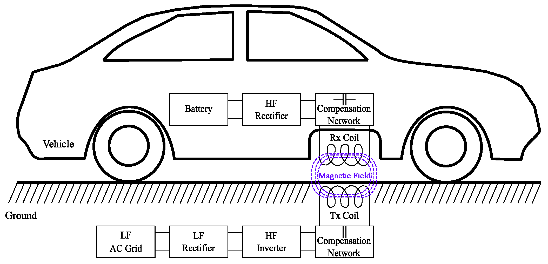
Figure 2.
Block diagram overview of a typical DIPT system applied to EV charging.
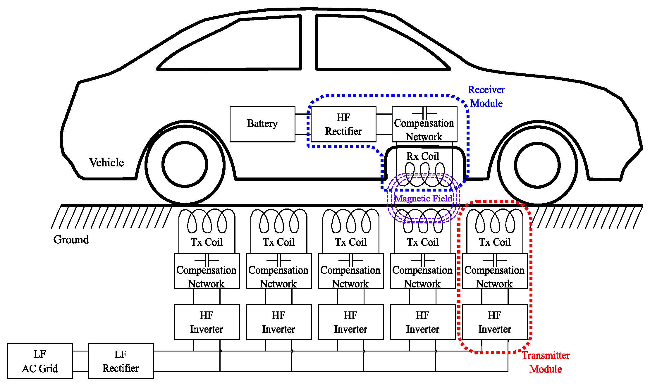
Figure 3.
Number of scientific publications on IPT systems between the years 1989 and 20227.
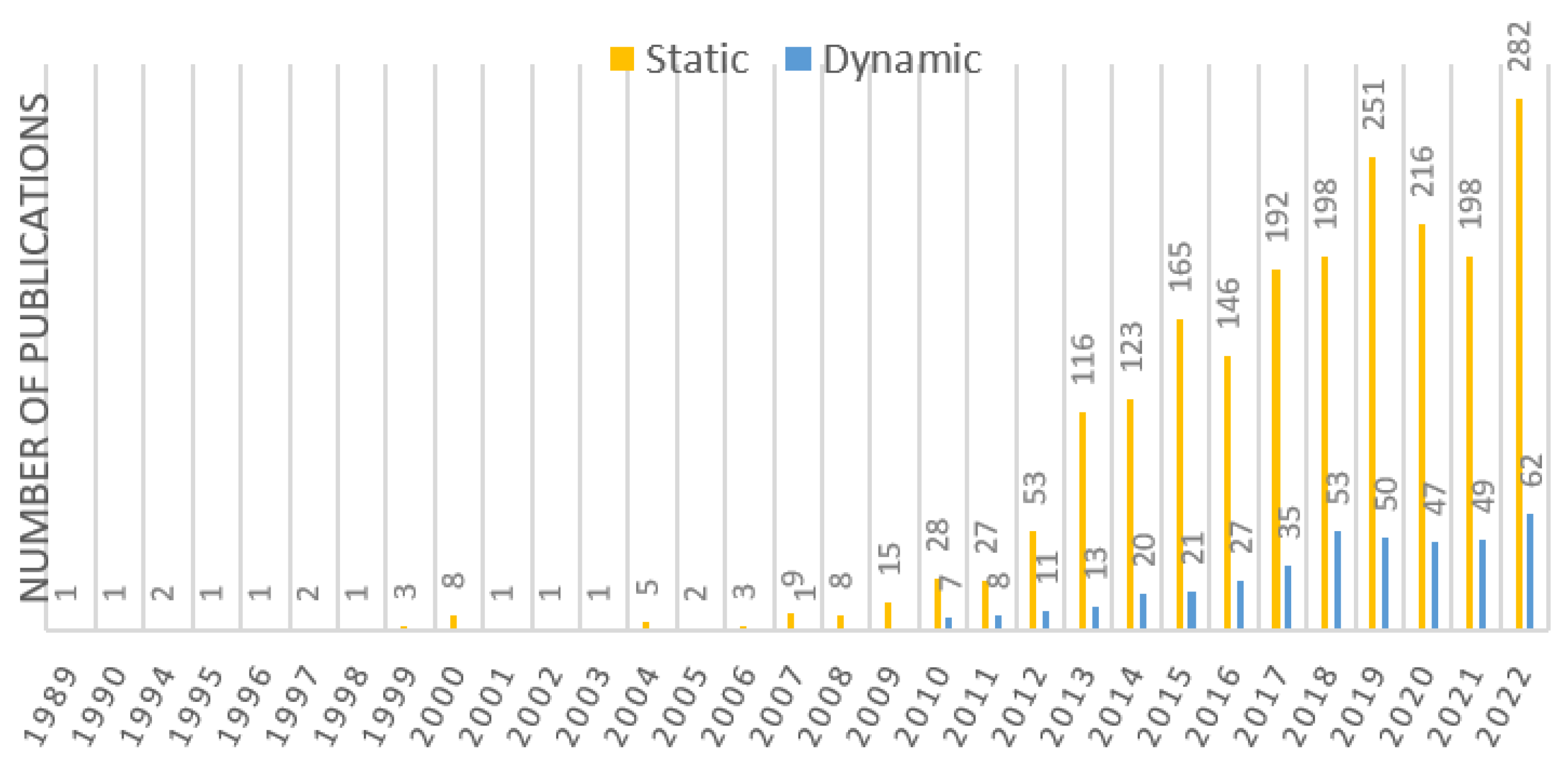
Figure 4.
Geographic coverage of authors' affiliations grouped by the number of publications (static + dynamic).
Figure 4.
Geographic coverage of authors' affiliations grouped by the number of publications (static + dynamic).
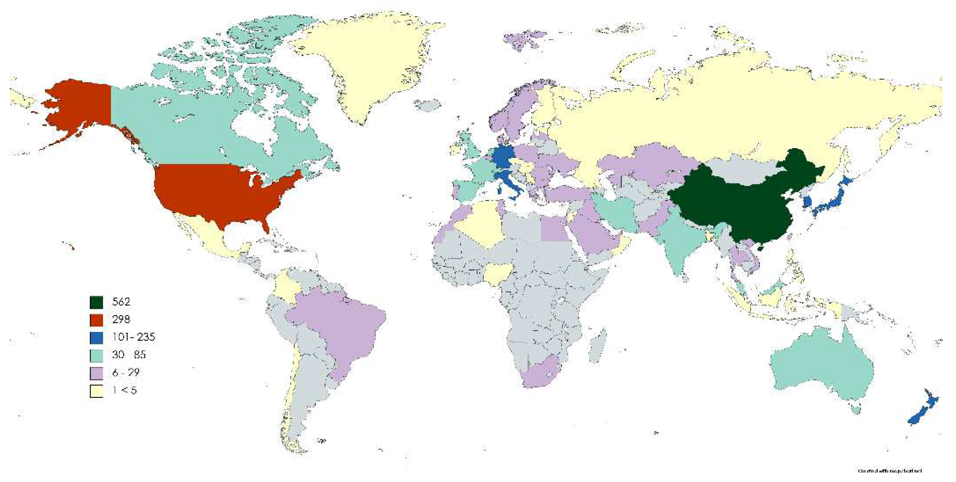
Figure 5.
Top contributors according to publication’s affiliation.
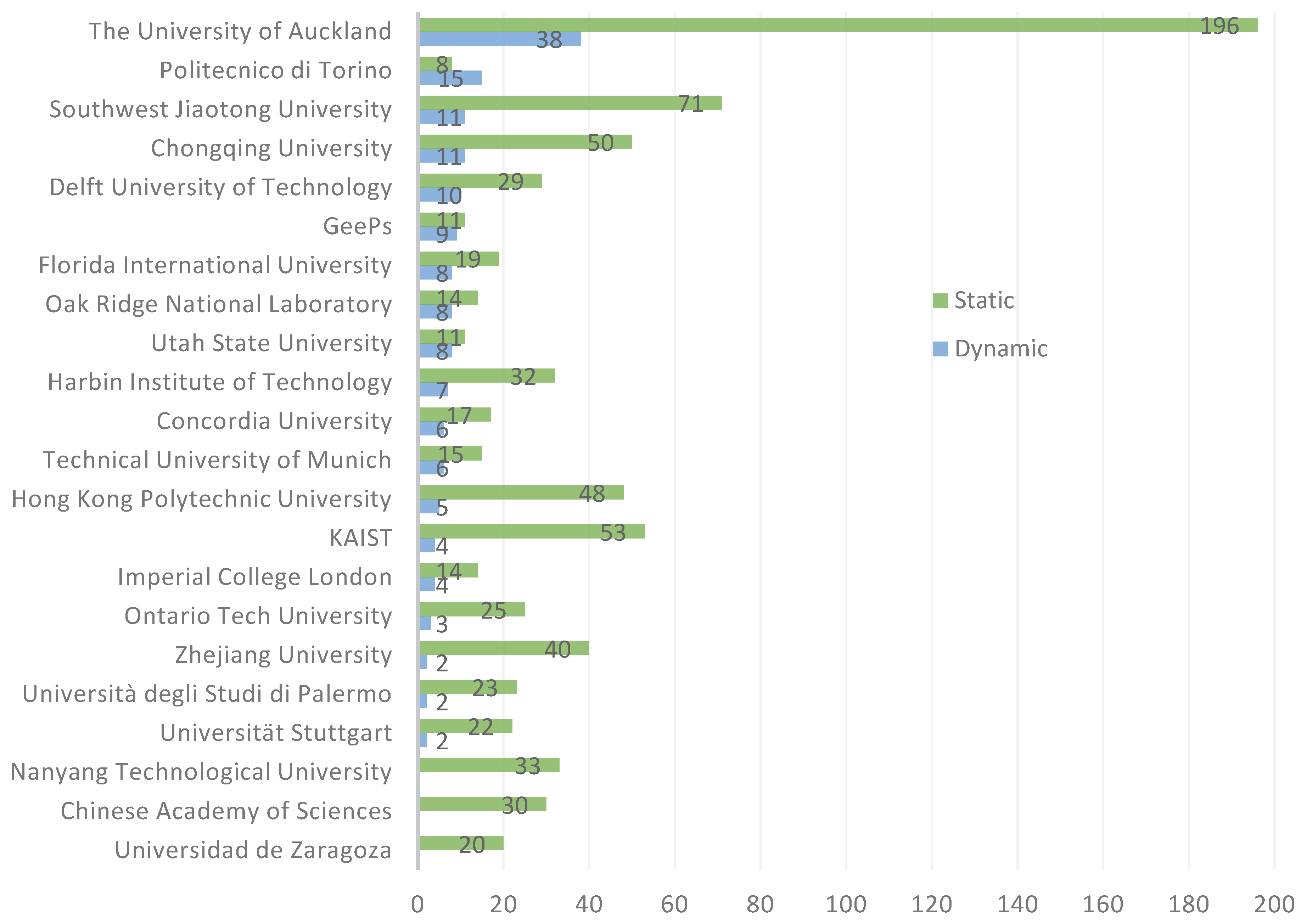
Table 3.
Reference levels for EMF exposure limits of the ICNIRP 1998/2010 Guidelines.
| ICNIRP 1998 | ICNIRP 2010 | |||||||
|---|---|---|---|---|---|---|---|---|
| Occupational Exposure6 | General Public Exposure7 | Occupational Exposure | General Public Exposure | |||||
| Frequency Range |
E-field Vm–1 |
Magnetic flux density µT |
E-field Vm–1 |
Magnetic flux density µT |
E-field Vm–1 |
Magnetic flux density µT |
E-field Vm–1 |
Magnetic flux density µT |
| 3 kHz – 65 kHz | 610 | 30.7 | 87 | 6.25 | 170 | 100 | 83 | 27 |
| 65 kHz – 150 kHz | 610 | 2000/f | 87 | 6.25 | 170 | 100 | 83 | 27 |
| Notes: | Values given in unperturbed RMS values f as indicated in the frequency range column |
|||||||
Table 4.
IEEE C95.1-2005 maximum permissible exposures (MPE) between 3.35 kHz – 5 MHz.
| Controlled Environment Exposure8 | General Public Exposure9 | |||
|---|---|---|---|---|
| Exposure of: |
E-field Vm–1 |
Magnetic flux density µT |
E-field Vm–1 |
Magnetic flux density µT |
| Head and torso | / | 615 | / | 205 |
| Limbs | / | 1130 | / | 1130 |
| Whole body | 1842 | / | 614 | / |
| Notes: | Values given in unperturbed RMS values The averaging time for an RMS measurement is 0.2 second |
|||
Disclaimer/Publisher’s Note: The statements, opinions and data contained in all publications are solely those of the individual author(s) and contributor(s) and not of MDPI and/or the editor(s). MDPI and/or the editor(s) disclaim responsibility for any injury to people or property resulting from any ideas, methods, instructions or products referred to in the content. |
© 2024 by the authors. Licensee MDPI, Basel, Switzerland. This article is an open access article distributed under the terms and conditions of the Creative Commons Attribution (CC BY) license (http://creativecommons.org/licenses/by/4.0/).
Copyright: This open access article is published under a Creative Commons CC BY 4.0 license, which permit the free download, distribution, and reuse, provided that the author and preprint are cited in any reuse.


