Submitted:
06 January 2024
Posted:
08 January 2024
You are already at the latest version
Abstract
In the article, the authors presented the problem of the transition effect in bridge engineering, its causes, negative consequences, and suggested a solution involving the use of integral bridges with the embankment through a spatial bars structure using reinforced composite polymer material. Integral bridges are designed to collaborate with road or railway embankments in bearing loads. Additionally, their application minimizes maintenance and construction costs while enhancing durability. Current solutions in bridge engineering were described. It is predicted that the presented concept will reduce the amount of plastic waste and contribute to the long-term use of materials. The article emphasized the importance of sustainable development, recycling, and the potential application of substitute materials.
Keywords:
civil engineering
; integral bridges
; transition zone
; transition effect
; reinforced polymer composite
; recycling
1. Introduction
The combination of adverse phenomena such as excessive deformations, dynamic impact, wear and tear and damage at the junction between an embankment and a bridge structure is defined as the transition effect. It occurs at points where different types of permanent way or pavement are connected, laid on various substrates (e.g., soil subgrade, engineering structures) [1,2]. The transition effect is a complex phenomenon, as illustrated in Figure 1, showing the most significant causes of its occurrence, including permanent settlements at abutments (usually smaller) and embankments (usually larger), progressing over time with unequal values for individual elements, and momentary deformations from live loads (deflection of girders, rails, and substrate deformations). Among the surface-related causes, differences in stiffness between the ballast and ballastless tracks, as well as varying stiffness parameters across the transverse direction, can be listed. It includes also primary geometric irregularities of rails and inaccurate alignment of the gradeline on and outside the facility. Causes related to the structure include, but are not limited to, primary geometric irregularities, deformations, settlement, and increased stiffness. Causes related to the substrate involve poor sub-ballast compaction, excessive stiffness differences between sub-ballast and substrate, sub-ballast contamination, and improperly chosen geotextiles. Due to different settlement values at the abutment and embankment, a so-called "threshold" is formed, which leads, among other reasons, to additional dynamic loads on the structure and excessive permanent deformations of the surface, amplifying dynamic effects and causing increased wear and tear and damage to pavement, track superstructure, substrate, and structure. Designing and constructing bridges with their associated embankments require special attention. These structures are often placed in locations where there are poorly compacted, young alluvial sediments, and sometimes clayey or peaty soils, which undergo significant settlement [3]. The issue of ensuring uniform support on the road or railway at the junction of an engineering structure and a deforming earthwork concerns most existing and renovated structures of this kind, to a lesser extent new lines, where the issue of non-uniformity can be largely prevented through the use of appropriate designs [4].
1.1. Engineering aspect
So far, clear requirements and solutions ensuring a gradual change in the substrate's stiffness for transition zones and reducing the effects of increased rolling stock actions in engineering structure areas have not been defined [4]. Currently, a commonly used solution to mitigate substrate stiffness changes is the transitional slab. However, analyzing the most common damages during the "lifetime" of structures, such as road pavement cracks and track superstructure deformations, suggests that the transitional slab might not be an entirely effective solution as it doesn't ensure a sufficiently gradual change in substrate stiffness (flexibility) [5]. Currently, very different design solutions for transition zones on railway lines are provided, but they do not include a comprehensive assessment of the transition effect.
In contrast to roads where transitional slabs are frequently used, they are not popular for railway lines. Instead, geosynthetics, draining and vibration-isolating mats, synthetic resins, stabilized soil blocks, reinforcement using stone columns or micropiles, dogging, chemical stabilization of sub-ballast, extending and widening substructures, and using stiffening rails within track rails are employed. Contemporary solutions sometimes also involve the use of reinforced concrete slabs.
Engineers often grapple with the durability issue of bridge structures. According to EC 0, bridges fall under category (class) S5, which implies an approximate design service life of at least 100 years. There are also structures over 200 years old still in use. Hence, the aspect of durability and safety of the structure while limiting construction and operation costs is crucial.
The elements with the shortest lifespan in bridge structures are expansion joints and bearings. The most advanced ones can operate for only about 30 years [6]. While piers and girders determine the bridge's load-bearing capacity, equipment elements significantly influence its durability and maintenance costs. The immediate cost of equipment element installation constitutes around 15-20% of the bridge construction cost. Their contribution to maintenance and repairs is often much higher, frequently exceeding 50% [7].
The question arises whether there is a type of bridge structure without a transition slab, expansion joints and bearings? These are frame structures, particularly integral bridges [5,6,7,8,9,10,11,12,13,14]. These are single or multi-span structures with a continuous deck connected to the abutment. The connection between the abutment and the deck can be rigid or semi-rigid, depending on the structural solution of the connection. The abutment can be articulated on the foundation or supported on piles. The fundamental structural solutions for these bridges are decks integrated with abutments based on shallow direct foundations, solid abutments, or partially integrated ones.
An integral bridge is a specific type of bridge structure designed to collaborate with an embankment in a way that minimizes the negative effects of the transition effect. The interaction between the integral abutment and the embankment is crucial to ensuring comfort and safety for its users.
Figure 2 shows an example of an integral bridge. In such cases, the embankment soil is often reinforced. As mentioned earlier, this type of structure does not have expansion joints, bearings, or transitional slabs. The integral abutment is usually incorporated into the road or railway embankment, reducing the bridge's impact on the environment and ensuring smooth and safe road or railway traffic.
The longitudinal forces arising from the thermal expansion or contraction of the bridge deck are transmitted to the abutments and to the soil behind the abutment [15]. In the design assumption, the abutment does not necessarily have to absorb the entire horizontal forces due to thermal effects, as part of them will be transferred to the embankment, which will be integrated into the cooperation [15]. Therefore, the crucial aspect is the connection between the abutment and the embankment.
In calculating the ground reactions behind the abutment, the total length of the bridge is significant, determining the extent of its expansion or contraction due to temperature changes. However, the number of intermediate supports has no effect on the magnitude of the bridge's expansion or contraction, and hence, this number doesn't influence the size of the ground reaction [7].
In integral bridges, forming a slip plane to stimulate movements in the upper layers of embankment soil is essential to minimize vertical displacements that affect the magnitude of the transition effect [7]. Intermediate supports, typically reinforced concrete, can be articulated on the foundation or based on one or several rows of piles. Spans for structures with integrated supports usually range around 60 meters, sometimes reaching 80-100 meters. The number of piers can vary, and the lengths of the longest integral bridges can exceed 350 meters (Happy Hollow Bridge, Tennessee, USA).
Integral bridges are designed with the assumption that only minor settlements of the end supports of the structure and embankments are permissible for using this solution in a given location. It is essential to note that this assumption significantly restricts the application of integral bridges.
Aware that the transitional slab does not entirely solve the transition effect issue and causes other negative effects, manifesting as pavement and track superstructure damages, designers of integral bridges opted for better cooperation between the embankment and the structure, abandoning the transitional slab [7]. The assumption of minor settlements in integral bridges mitigated the transition effect issue but significantly limited their applicability.
When entering a bridge, a vehicle must cross a transition zone. During its design, engineers must consider that the road or rail and the bridge itself may have different mechanical properties, such as stiffness, density, and Young's modulus. If the foundation at the entrance to the bridge is too stiff, it can lead to excessive stress in the bridge structure and increased risk of damage. Conversely, if the foundation is too soft, it may cause excessive settling of the bridge and a change in its geometry, which can result in hazardous situations for users. The mismatch usually occurs between a too compliant embankment and a too rigid bridge structure. Regulations seem to focus separately on the settling of individual elements, overly stiffening the structure (restrictively limiting deformations and settling) while overlooking the fact that soil structures will always settle more than those built from concrete and steel. Hence, it is reasonable to extend the bridge structure into the transition zone and connect it with a system that ensures efficient load transfer and smooth settling changes.
Reinforcing the ground behind the abutment is often used in bridge engineering to relieve the abutments. This is done by forming a block construction from reinforced soil, using geosynthetic materials, for instance. It can relieve the abutment bodies and wings of newly built bridges as well as existing ones. However, the resulting void between the back wall of the abutment and the embankment creates a discontinuity that can negatively impact operational qualities, increasing the transition effect.
By reducing the pressure on the abutment, its dimensions can be reduced, thus minimizing the difference in stiffness (compliance) between the surfaces. Ensuring load transfer cooperation and standardized settling is crucial. Geosynthetic reinforcement itself is not used due to its low stiffness compared to the abutment. However, these two mediums can cooperate effectively. This type of solution has been studied, among others, by Horvath [16].
The purpose of reinforcing the ground (or using layers) is to increase soil shear strength and reduce ground pressure on the abutment [7]. By reinforcing the embankment soil, uneven settling can be controlled. In the case of a significant increase in pressure on native soil, there is a risk of uneven settling or loss of stability. Using a reinforced platform allows for even distribution of settling [17]. The platform's effectiveness can be increased by using high-strength geosynthetic geogrids, with tensile strength up to 1600 kN/m, which vertically absorb, distribute, or dissipate loads onto the soil [17].
The problem of the transition effect, caused by the varying compliance (stiffness) of the pavement foundation in the transitional section onto the bridge, remains a current challenge for bridge engineers and continues to be researched and analyzed [10,11,13,14,15,16,18,19,20,21,22,23,24,25,26,27,28]. Intensity in addressing this issue has decreased in recent years, yet with increasing speed limits and tonnage, the problem is escalating. In the case of railways, any unevenness in the track profile gains importance due to the possibility of jolting rolling stock, uneven wear on rail heads, or damage or dislodgement of track beds. For traditional roads, damage occurs to the surface, followed by subsequent structural elements. The ever-growing volume of waste poses challenges to humanity. Seeking multi-faceted solutions contributing to the common good is the essence of engineers' and scientists' efforts. The issue of transition zones (and the transition effect within) in bridge engineering involves the use of numerous different solutions that are not standardized and have limited impact on reducing the set of adverse phenomena, such as excessive deformation, dynamic effects wear, and damage to surface elements, foundation, and the structure itself. There is an opportunity to propose solutions involving the use of processed waste in the construction of transition zones connecting abutments to embankments, where materials made from waste can fulfill their function and contribute to reducing environmental pollution.
Ensuring the durability of bridge structures places specific requirements on the durability of individual elements. Despite the increasingly modern solutions in bearing and expansion joint construction, reality verifies that production, assembly, and maintenance costs are significantly rising. There are also increasing demands for the qualification of personnel involved in assembly, maintenance, and replacement of individual elements during the operation of these structures. The growing number of structures poses increasing maintenance difficulties, necessitating the search for "simple" solutions. Integral bridges can be considered as such.
1.2. Environmental aspect
An effect of the increasing affluence of societies is the intensive growth in the quantity of waste generated. According to the World Bank report [29], currently, approximately 2 billion tons of solid waste are produced each year. Experts also predict that in about 30 years, we might expect nearly a doubling of garbage production. The enormous volume of waste poses a significant burden on the natural environment. Statistics indicate that an average resident of the European Union generates 530 kg of waste per year [30], of which approximately only 48% is processed. The share of polymer waste in recycling is only 25% [31].
Polymer materials are processed many times, which further reduces the need for limited resources, such as oil or gas, from which they are produced. However, it is important to note that with each subsequent recycling of polymer raw materials, their mechanical properties deteriorate. Essentially, after two cycles of plastic use (use - recycling - use), the material is no longer suitable for rational processing; its strength properties become too low [32]. It is desirable, therefore, to find a long-term use for waste material.
Comparing them to everyday items, the use of processed materials, especially in civil engineering like in bridge construction, ensures their long-term use, often exceeding 100 years. This fact can significantly reduce the carbon footprint of everyday products that eventually become waste. The issue of managing the increasing amount of waste from polymers has gained particular significance in recent decades, and if properly utilized, these can become valuable resources.
Special attention needs to be paid to waste from high-molecular-weight plastics. Their largest source is packaging. According to data [33], only about 19.5% of plastic waste is sorted. This fact guarantees a constant demand for solutions allowing for recycling.
According to the PlasticsEurope Foundation report [34] from 2022, in 2021, global production increased by 4% to over 390 million tons, indicating a strong and continuous demand for plastics. However, Europe faces many challenges. The latest data shows that China's share in global plastic production continues to grow (reaching 32% in 2021), while Europe's share - totaling 57.2 million tons in 2021 - continues to decline (reaching 15%). In 2021, the recovery of plastic waste in the 27 EU27+3 countries exceeded 5.5 million tons, post-consumer plastic waste used in new products and parts accounted for about 10% of plastic recycling and increased by about 20% compared to 2020 [34]. According to the cited report, global plastics production increased from 365.5 million tons in 2018 to 390.7 million tons in 2021. Plastic recyclates accounted for 30 million tons and 32.5 million tons respectively. A slight increase in the share of recyclates from 8.2% to 8.3% can be observed [35]. In 2022, in the EU27+3 group of countries, out of 17.9 million tons of plastic packaging, 17% was landfilled, 46% was recycled, and 37% was recovered for energy [35]. In two countries, Belgium and the Netherlands, the intended goal of complete elimination of landfilling of plastic waste was almost achieved [34].
In the EU27+3 group of countries, the percentage of waste going to landfills continues to decrease, but progress in this area is slow, especially in countries with a low level of plastic waste recovery. Half of the EU member states recover less than 30%. Every year, 25% of plastic waste in the EU27+3 still goes to landfills [36]. In Europe, 37% of plastic waste is incinerated in modern incinerators [34]. The above data is presented in Figure 3; the charts are based on information contained in [34,35]. A study by Zero Waste Europe showed that even the most modern incinerators emit dioxins and other harmful pollutants [37,38]. This situation encourages intensified efforts to increase the amount of recycled materials [36].
Many of the countries accepting waste perform poorly in plastic waste management rankings. According to the World Bank, in developing countries, "over 90% of waste often ends up in illegal landfills or gets burned [39]." Every product of plastic ever produced still exists today. Since 1950, 2 million tons of plastic have been created worldwide [34]. In studies [40], Roland Geyer et al. estimate that about 79% of all plastic waste ends up in landfills or directly in the natural environment. Ten million tons of plastic enter the oceans every year.
The cost of pollution is estimated in billions of dollars annually [41]. In 2019, an international research team published in the Marine Pollution Bulletin data stating that each ton of plastic waste in the oceans represents destroyed resources valued at up to $33,000. Scientists did not account for the indirect impact on tourism, transportation, and health. Considering these aspects, the social and economic costs of plastic waste in the oceans may be significantly underestimated [41].
The main challenges hindering plastic recycling are the quality and price of recycled products compared to their virgin counterparts. This is due to the complex process and various difficulties to overcome [42]. This includes sorting technology, specific challenges related to mechanical recycling like thermo-mechanical degradation or degradation over the product's lifespan, and the immiscibility of polymer mixtures. Plastic processors require large amounts of recycled plastics produced to tightly controlled specifications and at competitive prices [43]. However, plastics can be easily customized to meet the functional or aesthetic needs of any manufacturer, complicating the recycling process and increasing its cost while affecting the quality of the final product [43].
Green energy still faces challenges, especially in wind energy, where durable, lightweight materials like carbon fibers are needed for producing turbine blades. However, their rapid consumption and the lack of comprehensive solutions for processing these materials pose societal problems [44,45,46,47,48,49,50,51,52,53,54,55,56]. From 80% to 90% of wind turbine installations can be recycled (concrete, steel, copper, and silica). The remaining 10% to 20% represents a critical issue in disposing of the materials used to build them [44,45]. This concerns the materials in the blades, known as fiber-reinforced polymers (FRPs), often made of glass, carbon, aramid, or basalt fibers. In the EU, demand for FRPs grew sharply from 5,000 tons in 1991 to 346,000 tons in 2015. It is estimated that by 2030, 4 million tons of fiber-reinforced polymers will be used for zero-emission wind energy production in the European Union. Current recycling methods proposed do not solve the rapid increase in the amount of this type of waste [44].
Currently proposed actions in this area include: prevention, involving services and repairs of turbine blades to enable their extended use; reusing them in other sectors of the economy, producing items like small architectural elements, playgrounds, furniture, and similar products. However, low processing capabilities and the dust generated during processing are issues; recovery through chemical or thermal treatment, which is currently unprofitable; disposal through landfilling and incineration, which do not solve the problem and are banned in many countries; additionally, they are not in line with the principles of a circular economy [44].
In Germany alone, where 30,000 wind turbines are currently operating, by 2024, 70,000 tons of materials from turbine blades are expected to be scrapped. Most of these devices will then be dismantled. The German Federal Environment Agency calls on the government and regional authorities to quickly develop regulations and procedures for recycling decommissioned turbines [45]. Wind turbines installed in the United States in the late 1990s are gradually being decommissioned after 25 years of operation. A massive graveyard of buried turbine blades from decommissioned turbines is located in Casper, Wyoming. Until recently, a morally questionable practice occurred on a large scale, where dismantled wind farms were sold to markets in Eastern and Southeastern Europe, Russia, Africa, Asia, and Latin America. However, requirements in these countries are constantly increasing, and most are no longer interested in acquiring old technology that requires significant investment in maintaining such installations [45,50,53,54,55]. Extracting fibers using pyrolysis and using them as dispersed reinforcement in polymer materials will certainly help manage large quantities of this specialized waste to some extent.
Currently, the simplest and most effective way of waste disposal appears to be the use of materials in civil engineering as construction materials. Construction accounts for the use of 4 million tons of recyclables in new products for EU27+3 countries, which constitutes 46% of plastic recyclables [36]. The demand for materials for constructing embankments is very high. For standard embankment heights near bridge structures, this amounts to tens of cubic meters per meter of embankment using materials with a long period of use, as shown in Table 1.
2. Keyword analysis
Before delving into a detailed analysis of available literature related to the proposed topics in this publication, a scientometric analysis was conducted based on publicly available library catalogs. This analysis aimed to highlight the major scientific trends and areas requiring in-depth research. It facilitates the creation of visualizations for data analysis and establishes connections between sources, keywords, authors, and articles within a specific research area. Researchers from various fields of science utilize scientometric analysis [57,58,59,60,61].
Currently, scientists have access to a substantial collection of library catalogs promoted by various publishers. Below are the results of the analysis for widely accessible and most reliable databases, Scopus, and Web of Science [61,62]. Scopus is a scientific database managed by Elsevier, providing information about published scientific works such as articles in scientific journals, books, conference materials, and patents. As of November 2023, the database contained over 93 million records, encompassing more than 28,000 active titles published by over 5,000 publishers [63]. Additionally, it indexed around 327,000 books.
The indexed works in the database cover natural sciences, engineering, medical, social, humanities, and arts [63]. Web of Science, also a scientific database managed by Clarivate, contains similar information about published scientific works. As of November 2023, it contained over 211 million records, including books, articles, and other materials [64]. The thematic scope of the indexed works in this database is also similar. The data search was conducted in November 2023, using keywords such as 'civil engineering, integral bridges, transition zone, transition effect, reinforced polymer composite, recycling.'
Due to the multifaceted nature of this article, the explored topics covered various fields, including civil engineering, material engineering, chemical engineering, chemical sciences, environmental engineering, environmental sciences, and resulted in the following Table 2, presenting results for individual combinations of keywords. While analyzing the results, it is worth noting that the orders of magnitude of the presented results from different databases correspond with each other, with minor exceptions. These differences may arise from the search criteria offered. Unlike Scopus, Web of Science did not have a defined limit to searching only titles, abstracts, and keywords. It is crucial to highlight that as the number of keywords increases, the search results drop to zero. This clearly indicates that the presented scope requires further research.
The initial high values of association results do not clearly reflect the content relationship presented in the publications with this study. Often, the overlap of two keywords is far from sufficient. Only with three keywords do single articles begin to share common parts.
Data from Scopus and Web of Science databases for selected searches (3 and 4 keywords) were exported in comma-separated values (CSV) format for importing into the appropriate software tool. Mapping and visualizing the academic network were created using the VOSviewer software version (developed by the Centre for Science and Technology Studies of Leiden University, Leiden, Netherlands). VOSviewer is a software tool used to construct and visualize bibliometric networks based on citations, bibliographic couplings, co-citations, or co-authorship relations [65].
The visualization of co-occurrence networks of keywords, their relationships, and the density associated with the frequency of their correlations were examined and presented in Figure 4andFigure 5. The size of the keyword node denotes its frequency, while its location represents its co-occurrence in publications. To enhance clarity in the presented data, the engineering material part related to integral bridges was separated and displayed in Figure 4. The entirety of connections is shown in Figure 5a, with a detailed engineering part in Figure 5b, which was subdued due to the material scope.
To identify clusters for Figure 4 among over 550 author keywords in separate publications, those appearing a minimum of 2 times were selected, reducing the number of analyzed words to 40. This demonstrates a significant diversity of topics and areas. Words that were entirely unrelated thematically were excluded from the visualization, leaving around 30. In the case of Figure 5, the number of analyzed keywords was 354. Many weakly connected words imply their infrequent occurrences, being referenced only a few times with other analyzed words from different texts. This indicates the vast fragmentation within the research area.
The visualization can not only assist in finding trends but also aid future authors in selecting presented keywords to find published data on specific topics.
The results presented in 5a,b indicate that topics related to bridge engineering have been less frequently addressed in recent years. Popular areas in publications seem to revolve around recycling and the use of reinforced polymers. However, there is a lack of keyword connections between bridge-related topics and the use of reinforced polymer composites, not to mention the transision effect, for which there is a minimal number of keywords. The analysis presented clearly indicates the necessity for further research in the highlighted subject matter.
3. General purpose of research
The aim of this review article is to showcase the current solutions in bridge engineering, focusing on reducing the transition effect and emphasizing the significance of the problem. Additionally, the issue of plastic recycling in the context of utilizing them as an advanced material base for construction has been outlined.
4. Research area
The research area focused on assessing transition effects using post-consumer polymer materials is multifaceted. In today's world, solving individual problems in the short term is challenging. When advancing knowledge in one field, it is essential to consider whether materials available in other areas might be useful for solutions. Therefore, construction itself generates a large demand for materials and can effectively utilize materials that are considered waste in other sectors.
This study addresses aspects such as:
- Engineering Aspect: Current projects do not entirely solve the issue of stiffness discontinuity (flexibility) in the subgrade for linear structures approaching bridges. According to the authors, further progress supported by appropriately developed materials and the spatial structure of the joint construction will undoubtedly enrich contemporary bridge engineering with new design solutions that could reduce the transition effect. Introducing a new medium into the structure will affect the behavior of the structural abutment system and directly link it to the embankment. It will enhance load transfer through a complex structure onto different material centers and provide a smoother change in stiffness (flexibility) of the subgrade for linear structures.
- Environmental Aspect: The new material and its application area offer opportunities to utilize large amounts that accumulate in landfills or are incinerated. It is important to note that these materials could be reused (to be confirmed by planned future research). Due to their longevity anticipated in engineering constructions, the properties of processed waste will serve future generations. Pursuing the idea of sustainable development involves seeking applications for waste considered inefficient, difficult, or costly to process. This fact guarantees a constant demand for solutions enabling recycling.
6. Description of the concept of reducing the transition effect using a spatial polymer bar structure
In reference to the aforementioned issues, the authors propose the design of a composite material composed of a polymeric matrix reinforced with recycled carbon fiber. It is anticipated that from a material with a rationally chosen spatial geometry, a structure ensuring lasting cooperation between the abutment and the embankment can be designed, thereby expanding the possibilities of integral bridges, minimizing the requirement for limited settlements, and reducing the transition effect. A visualization of the preliminary concept is shown in Figure 10 and Figure 11. Proper shaping of the near-abutment zone, as well as the abutment structure with anchored rod elements enforcing the abutment's interaction with the embankment and the surrounding zone, will provide a gradual change in the subsoil's stiffness along the transition zone, consequently reducing the transition effect [208].
The geometry of the bar structure arises from the analysis of finite element method (FEM) computational models of various engineering structures. Tetrahedral elements make the computational models to rigid. Due to this phenomenon, designers tend to avoid such elements in constructing accurate models that reflect reality. The phenomenon described above is planned to be applied more effectively to stiffen the embankment soil. Disign the presented configuration began with triangles, which were then transformed into tetrahedra, further evolving into a spatial mesh based on a regular dodecahedron.
As widely known, we cannot create a spatial mesh from regular tetrahedra. The closest geometric solid whose elements would resemble tetrahedra is indeed a regular dodecahedron, where the components consist of equilateral triangles with a similar ratio to the equilateral triangle. Hence, the appearance of the presented mesh. The genesis of its formation is shown in Figure 12. This is one of the initial concepts that will be further analyzed and confirmed by subsequent work. However, such a mesh has an additional advantage—it radiates outward radially in all directions from the central point. If such a point were designed at the center of the abutment mass, the effect of the generated cooperation could be impressive.
Due to their exceptional properties, polymers are increasingly being used as construction materials for bridge structure. The application of polymers as construction materials or their components is the best proof of how the construction industry can adapt modern materials to its own needs. An example of such adaptation is Fiber Reinforced Polymer (FRP) composite materials, where polymers are reinforced with fibers [150,199].
In composite materials, glass, carbon, basalt, or aramid fibers are used as reinforcing fibers [6,143,145,179]. In recent years, polymers have gained popularity due to their lightweight, durability, corrosion resistance, flexibility, and ease of shaping. Polymers are used in various structural elements of bridges, such as girders, cables, beams, and spans. For instance, the use of carbon fiber, one of the most popular polymers in bridge construction, is a good example. Carbon fibers are highly resistant while remaining lightweight, making them an ideal material for bridge structures. The use of carbon fiber helps reduce the mass of the structure, subsequently lowering production, transportation, and assembly costs.
PET (polyethylene terephthalate or poly(ethylene terephthalate)) is a waste plastic material with excellent strength properties [149,151,156,204,209]. It is the most commonly processed material. However, as mentioned earlier, it is not feasible to rely entirely on recycled raw material because with each processing, the long polymer chains fragmentize, causing a loss in strength properties. Therefore, adding virgin material in the recycling process is necessary to maintain the required strength properties. Consequently, it is evident that there will always be a continuous influx of material for processing. Hence, finding a long-term use for the material to extend its service life is crucial. It appears that PET, as a matrix for carbon fibers, has potential applications [156,204,209,210]. The real strength (relative to density) in Table 3 shows that it could be a more efficient material than steel. In most structures, it is the self-weight that constitutes the majority of the loads, if it is significantly optimized thanks to innovative light and durable materials, engineers will be able to create more advanced structures.
The primary requirement in constructing a bridge abutment along with an embankment is to ensure smooth passage between these entities. Irregularities not only accelerate vehicle wear but also pose a danger to those traveling at high speeds. They also contribute to increased dynamic forces exerted on bridge structures by vehicles. Reducing the pressure from reinforced ground fill involves the occurrence of frictional forces between the ground and the reinforcement. Regardless of increasing the soil's shear strength and reducing the pressure on the abutment, reinforced ground provides a more even distribution of deformations. This is particularly crucial in the case of integral bridges, where due to temperature changes, displacements of the ground behind the abutments alter direction multiple times [7].
Polymers are actively utilized to reduce the transition effect. An example is the use of polyurethane material as an adhesive that gradually stiffens the subgrade along the transition zone. To achieve a gradual change in stiffness, Chinese scientists proposed using a polyurethane-bound sub-ballast [205,206]. In this scheme, the bonding surface of the aggregate with the polyurethane determined the variation in subgrade stiffness. This solution was adapted in China for the transition zone of a railway line at the entrance to a tunnel, where the ground changed from flexible to the rigid concrete of the portal.
Polymers are employed as reinforcing materials in various construction projects, and there is substantial scientific research confirming their strength properties [140,141,180,211]. The above literature demonstrates that polymers can have numerous applications in the construction of bridge abutments and embankments, both as structural materials and auxiliary substances. It is worth noting that there is not an abundance of scientific studies linking recycled polymers with bridge construction, particularly with abutments, embankments, and transition zones. This area remains niche and requires interest from scientists.
7. Future and perspectives
In future research on the proposed solution, a critical aspect will be the integration of the abutment with the ground using reinforcing bars, along with selecting the composite's composition and shaping the geometry of the bar structure to achieve the required stiffness. The authors are currently exploring the possibility of processing PET polymer (polyethylene terephthalate) with reinforcing fibers. In the PET recycling process, primarily used for new bottle production, issues arise from contaminated materials (adhesives, labels, chemicals) that can't be used in products intended for food contact. Consequently, it is essential to find solutions where such limitations do not apply.
The use of polymers as construction materials or their components is a testament to how the construction industry can adopt modern materials to meet its needs. An analogy to such adaptation is the composite materials with a polymer matrix and fibrous reinforcement (FRP–Fiber Reinforcement Plastics).
Material recycling (using minimally processed material) can significantly manage large quantities of waste (Table 1) and ensure their utility for an extended period. Material recycling represents ways to utilize waste material in line with sustainable development principles, also enabling the production of construction material with unique properties. Its natural application area is in transportation infrastructure, where natural materials can be replaced by high-quality recycled materials.
The construction of transportation infrastructure involves increasingly larger structures. This leads to increased vertical loads on the ground and, in the case of bridges and retaining structures, additional horizontal forces (pressure). The most commonly applied solutions to these problems are costly ground reinforcement techniques (such as piling, various types of columns) or enhancing slope stability and retaining structures (using ground anchors or nails). Moreover, the availability of high-quality natural materials (coarse sands, gravels, aggregates) is often limited, and their transportation over significant distances is uneconomical. An alternative, more cost-effective solution to these issues might involve the use of substitute materials.
The resources of polymer waste are continually growing. The planned material's utilization in the construction and modernization of roads, railways, and broadly understood bridge structures can be particularly efficient. Employing polymers as one of the building blocks of engineering structures, ensuring long-term usage, will undoubtedly aid the poorest countries in managing their waste. The solution primarily lies in designing a spatial bar structure that expands the integral bridge abutments and their connection with the embankment to establish load transfer cooperation and limit differential settlements.
8. Research gaps
There is a clear gap in the potential use of composites made from recycled materials in shaping transition zones in integral bridges. The future perspective aims to propose a new design solution for the bridge support structure based on the system of integral bridges, where the abutment will be closely linked to the embankment. In the future, a spatial structure will be designed and analyzed, ensuring cooperation between the structures. Through this, the change in the stiffness (flexibility) of the subgrade along the length of the structure and transition zones will be gradual, predicting a significant reduction in the transition effect.
Another probable outcome of the research will be an expanded scope for the use of integral bridges, which won't be significantly restricted by the requirement for minimal settlements under the bridge supports and embankment. As mentioned, elements such as transition slabs, expansions, and bearings are not present in this type of structure. The absence of these elements will have a favorable impact on reducing the construction and maintenance costs of bridge structures.
It is anticipated that the designed structure will be composed of a composite made of polymer reinforced with dispersed fibers, with a direct and clearly defined correlation between the composition and the 'stiffness' of the resulting material. The 'stiffness' of the material and its geometric arrangement will directly influence the stiffness of the designed embankment structure.
The priority selection of components involves utilizing waste in the form of polymers in recyclate form and recycled fibers. The anticipated use of these raw materials will significantly reduce the carbon footprint and effectively utilize materials (the expected durability of bridge structures is at least 100 years). The scope of the study will, in the near future, encompass a comprehensive exploration of the issue, starting from theoretical analysis of computational models and concluding with laboratory research and a description of the proposed solution.
9. Summary
The issue of transition zones and the transition effect in bridge engineering is associated with the use of various solutions that lack standardization and have a limited impact on reducing the discussed phenomenon. This topic has been known for quite some time. With the development of transportation, increasing cargo tonnages, and rising speeds, research in this area becomes necessary. There's a visible opportunity to propose solutions involving the utilization of processed waste in constructing zones connecting abutments with embankments. However, it's crucial to emphasize that polymers, including reinforced polymers, especially those made from recyclables, are not widely used in bridge construction, and their impact on reducing the transition effect hasn't been thoroughly explored. The idea of sustainable development, recycling, and environmental aspects should be incorporated into every field.
In the article summary:
- It has been highlighted the relevance of the transition effect problem in bridge structures and the need for exploring new solutions. It has been proposed a solution related to integral bridges, allowing the avoidance of expansion joints and bearings, which positively impacts durability and maintenance costs. Transition slabs often do not completely eliminate this and may cause damage;
- It has been emphasized the importance of sustainable development, especially in the context of plastic waste management, drawing attention to the recycling potential in construction, the use of composite materials based on recyclables reinforced with fibers in bridge engineering, contributing to waste reduction and sustainable utilization of recycled materials;
- It has been Indicated that the possibility of using substitute materials, appropriately processed and shaped, might find application in bridge engineering, representing a cheaper and more ecological alternative to traditional solutions;
- It has been highlighted PET (polyethylene terephthalate) as having the best strength properties among waste plastics and exhibiting good capabilities for creating composites with fibers.
It has been presented a prospective approach to bridge design, considering technical, durability, and environmental aspects through the utilization of innovative solutions and materials, which could lead to more sustainable and efficient construction practices in the future. The presented topic is related to a doctoral thesis, and at this stage, concepts aligned with sustainable construction trends and the principles of the 6Rs are being formulated.
Author Contributions
Conceptualization, M.S.; methodology, K.A.O. and K.F.; investigation, K.A.O.; resources, K.A.O.; writing—original draft preparation, M.S., K.A.O., and K.F.; editing, M.S., K.A.O., and K.F.; supervision, K.A.O., and K.F.; project administration, K.A.O.; validation, M.S., K.A.O., and K.F.; formal analysis, K.A.O., and K.F.; writing—original draft preparation, M.S., K.A.O. and K.F.; visualization, M.S.; funding acquisition, K.A.O. All authors have read and agreed to the published version of the manuscript.
Funding
This research received no external funding
Institutional Review Board Statement
Not applicable.
Informed Consent Statement
Not applicable.
Data Availability Statement
The data are contained within the article.
Conflicts of Interest
The authors declare no conflict of interest.
References
- Sołkowski, J. Zarys analizy efektu progowego przy łączeniu nawierzchni podsypkowych z innymi typami nawierzchni. 2009; 12, 59–65. [Google Scholar]
- Sołkowski, J. Efekt progowy w nawierzchniach szynowych. Monografia 435. 2013. [Google Scholar]
- Cyunel, B.; Kulczycki, B. Kolejowe budowle ziemne, T. II–Technologia, organizacja budowy i modernizacji, 1987. [Google Scholar]
- Skrzyński, E. Osiadania podtorza gruntowego, Prace Instytutu Kolejnictwa, 2019, Zeszyt 161, 28–43.
- Bień, J. Uszkodzenia i diagnostyka obiektów mostowych, 2010.
- Vademecum Budownictwo Mostowe, 2016.
- Furtak, K.; Wrana, B. Mosty Zintegrowane, 2005.
- Musiał, T. Obiekty mostowe z przyczółkami zintegrowanymi, 2012.
- Steffen, M.; Chongjie, K. A new generation of integral high speed railway bridges, 2019, 11, 514–518.
- Capija, M.; Madaj, A. Mosty zintegrowane, 2008, 4, 81-83.
- Capija, M.; Madaj, A. Doświadczenia z projektowania i eksploatacji mostów zintegrowanych, 2010, 4, 50–53.
- Arsoy, S.; Barker, R. M.; Duncan, J. M. The behavior of integral abutment bridges, 1999.
- Burke, M. P Jr. Integral & Semi-Integral Bridges, 2009.
- Burke, M. P Jr. Integral Bridges, 1990.
- Jarosz, J. The effect of braking forces on displacement of integral bridges, 2013.
- Horvath, I.S. Integral-Abutment Bridges: Problems and Innovative Solutions Using EPS Geofoam and other Geosynthetics, 2000.
- Duszyńska, A. Zbrojenie geosyntetyczne podstawy nasypu, 2016.
- Jarosz, J. Experimental verification of numerical model of integral bridge, 2014, 3, 103–110.
- Sołkowski, J.; Kudła, D. Analiza niejednorodności mechanicznych nawierzchni i podtorza w obrębie obiektu mostowego. Zeszyty Naukowo-Techniczne SITK RP, Oddział w Krakowie 2016, 2, 165–175. [Google Scholar]
- Sasaoka, D. Track transition designs for heavy-axle-load service: analyses of track transition issues at bridge approaches, road crossings and special track work find ways to minimize track stiffness and maximize maintenance dollars. TTCI R&D. Railway Track and Structures, 1 April 2006. [Google Scholar]
- Kłosiński, B.; Niemierko, A. ERRI D 230.1/RP 3: Bridge Ends. Embankment Structure Transition, State of the Art Report, Utrecht. November 1999. [Google Scholar]
- Kłosiński, B.; Niemierko, A. Wzmacnianie stref przejściowych na dojazdach do mostów kolejowych. Archiwum Instytutu Inżynierii Lądowej 2012, 4. [Google Scholar]
- Alves, A.C.; Calcada, R.; Delgado, R. Dynamic effects induced by abrupt changes in track stiffness in high speed lines. Applications of Comp. Mech. in Geotechnical engineering - Sousa, 2007; 473–483. [Google Scholar]
- ČD S4 Železnični spodek - Přechodtělesażelezničního spodku na mostníobjekty, Příloha 24, 1998.
- Davis, D.D. Bridge approach performance in revenue service. Railway Track and Structures, Dec. 2003, pp. 18-20.
- Davis, D.; Plotkin, D. Track settlement at bridge approaches: what causestrack settlement at bridge approaches and how can railroad engineering departments deal with the problem safely and efficiently? Railway Track and Structures, February 1 2009.
- Diaz, A. La construcción de terraplenes y desmontes. Fundación de los Ferrocarriles Espanoles, 1993. [Google Scholar]
- Eisenmann, J. Dűrchfűrung von Dauerschwellversuchen an einer Űbergangkonstruktion. Technische UniversitatMűnchen, 1985-1990, (raport z badań).
- Raport Banku Światowego „What a Waste 2.0: A Global Snapshot of Solid Waste Management to 2050”.
- Dane statystyczne Eurostat 2021.
- Dane statystyczne GUS 2021.
- Dane statystyczne Organizacji UNESCO 2022.
- Dane statystyczne Fundacji PlasticsEurope 2022.
- Raport Fundacji Plastik Europe z 2022 „Reshaping Plastics: pathways to a circular, climate neutral plastics system in Europe”.
- Company research data Conversio Market & Strategy GmbH.
- Raport Fundacji Plastik Europe z 2021 „Tworzywa w obiegu zamkniętym”.
- Arkenbout, A. Hidden emissions: A story from the Netherlands Case Study, Zero Waste Europe, 2018.
- Dane statystyczne Organizacji Zero Waste Europe.
- Dane statystyczne Banku Światowego 2021.
- Geyer, R.; Jambeck, J.R.; Law, K.L. Production, use, and fate of all plastics ever made. Sci. Adv. 2017, 3, e170078. [Google Scholar] [CrossRef]
- Marine Pollution Bulletin, The Guardian, WWF, Santa Barbara Marine Conservancy.
- Ragaert, K.; Lauren, D.; Geem, K.V. Mechanical and chemical recycling of solid plastic waste. Waste Management, 2017, 69, 24–58. [Google Scholar] [CrossRef]
- European Parliament | Plastic waste and recycling in the EU: facts and figures. Available online: https://www.europarl.europa.eu/news/en/headlines/society/20181212STO21610/plastic-waste-and-recycling-in-the-eu-facts-and-figures (accessed on 20 November 2023).
- Raport końcowy: Badanie ewaluacyjne, pn. „Recykling wyeksploatowanych komponentów technicznych odnawialnych źródeł energii oraz akumulatorów pojazdów elektrycznych jako element transformacji w kierunku gospodarki o obiegu zamkniętym”, Wroconsult Sp. z o.o. oraz Ekovert Łukasz Szkudlarek na zlecenie Ministerstwa Energii.
- Drozdowski, W. Łopaty turbin wiatrowych najtrudniejsze do recyklingu, Centrum Informacji o Rynku Energii 2020. Available online: https://www.cire.pl/artykuly/opinie/155372-lopaty-turbin-wiatrowych-najtrudniejsze-do-recyklingu (accessed on 20 November 2023).
- Wronka, K. Pełny recykling łopat turbin wiatrowych - przyszłość czy złudna nadzieja?, Centrum Informacji o Rynku Energii 2022. Available online: https://www.cire.pl/artykuly/brak-kategorii/pelny-recykling-lopat-turbin-wiatrowych---przyszlosc-czy-zludna-nadzieja (accessed on 20 November 2023).
- Abdallah, R.; Juaidi, A. ; Savas ̧, M.A.; Çamur, H.; Albatayneh, A.; Abdala, S.; Manzano-Agugliaro, F. A Critical Review on Recycling Composite Waste Using Pyrolysis for Sustainable Development. Energies 2021, 14, 5748. [Google Scholar] [CrossRef]
- Albers, H. Recycling of wind turbine rotor blades–fact or fiction? DEWI Mag 2009, 34, 32–41. [Google Scholar]
- Dannemand Andersen, P.; Borup, M.; Krogh, T. Managing long-term environmental aspects of wind turbines: a prospective case study’, Int. J. Technology, Policy and Management 2007, 7, 339–354. [Google Scholar]
- Liu, P.; Barlow, C.Y. Wind turbine blade waste in 2050. Waste Manag 2017, 62, 229–240. [Google Scholar] [CrossRef] [PubMed]
- Liu, P.; Meng, F.; Barlow, C. Wind turbine blade end-of-life options: an eco-audit comparison. J. Clean. Prod. 2019, 212, 1268–1281. [Google Scholar] [CrossRef]
- Lefeuvre, A.; Garnier, S.; Jacquemin, L.; Pillain, B.; Sonnemann, G. Anticipating in-use stocks of carbon fibre reinforced polymers and related waste generated by the wind power sector until 2050. Resour. Conserv. Recycl. 2019, 141, 30–39. [Google Scholar] [CrossRef]
- Urząd Regulacji Energetyki | Moc zainstalowana MW stan na 31.12.2020. Available online: https://www.ure.gov.pl/pl/oze/potencjal-krajowy-oze/5753,Moc-zainstalowana-MW.html (accessed on 20 November 2023).
- WindEurope | Wind energy in Europe 2020 Statistics and the outlook for 2021-2025. Available online: https://windeurope.org/intelligence-platform/product/wind-energy-in-europe-in-2020-trends-and-statistics/ (accessed on 20 November 2023).
- Ziegler, L.; Gonzalez, E.; Rubert, T.; Smolka, U.; Melero, J.J. Lifetime extension of onshore wind turbines: a review covering Germany, Spain, Denmark, and the UK. Renew. Sustain. Energy Rev. 2018, 82, 1261–1271. [Google Scholar] [CrossRef]
- Ziegler, L.; Muskulus, M. In Proceedings of the Lifetime extension of offshore wind monopolies: Assessment process and relevance of fatigue crack inspection. EAWE PhD Seminar on Wind Energy in Europe, Location of DTU Lyngby, Denmark, May 2016. [Google Scholar]
- Perron, B.E.; Victor, B.G.; Hodge, D.R.; Salas-Wright, C.P.; Vaughn, M.G.; Taylor, R.J. Laying the foundations for scientometric research: A data science approach. Res. Soc. Work. Pract. 2017, 27, 802–812. [Google Scholar] [CrossRef]
- Zitt, M.; Bassecoulard, E. Challenges for scientometric indicators: Data demining, knowledge-flow measurements and diversity issues. Ethics Sci. Environ. Politics, 2008, 8, 49–60. [Google Scholar] [CrossRef]
- Singh, V.K.; Banshal, S.K.; Singhal, K.; Uddin, A. Scientometric mapping of research on ‘Big Data’. Scientometrics, 2015, 105, 727–741. [Google Scholar] [CrossRef]
- Gile, D. Analyzing translation studies with scientometric data: From CIRIN to citation analysis. Perspectives 2015, 23, 240–248. [Google Scholar] [CrossRef]
- Falagas, M.E.; Pitsouni, E.I.; Malietzis, G.A.; Pappas, G. Comparison of PubMed, Scopus, web of science, and Google scholar: Strengths and weaknesses. FASEB J. 2008, 22, 338–342. [Google Scholar] [CrossRef]
- Vieira, E.; Gomes, J. A comparison of Scopus and Web of Science for a typical university. Scientometrics 2009, 81, 587–600. [Google Scholar] [CrossRef]
- Scopus | Abstract and citation database. Available online: https://www.elsevier.com/products/scopus/ (accessed on 20 November 2023).
- Web of Science Coverage Details - Resources for Librarians. Available online: https://clarivate.libguides.com/librarianresources/coverage/ (accessed on 20 November 2023).
- Visualising Scientific Landscapes. Available online: https://www.vosviewer.com/ (accessed on 20 January 2023).
- Rymsza, J.; Biliszczuk, J.; Onysyk, J.; Toczkiewicz, R. Wytyczne projektowania elementów powiązania drogowych obiektów inżynierskich z terenem i drogą. Wzorce i standardy rekomendowane przez Ministra właściwego ds. transportu. 2020.
- Standardy techniczne–szczegółowe warunki techniczne dla modernizacji lub budowy linii kolejowych 2018-2023.
- Binder, K. Strefa przejściowa pomiędzy obiektem mostowym a nasypem drogowym. Mosty 2012, 4, 55–57. [Google Scholar]
- Hebda, M. Materiały dydaktyczne–Utrzymanie i remonty mostów. Politechnika Krakowska, Wydział Inżynierii Lądowej 2020.
- Krupka, J.; Sobala, D. Stan techniczny mostów zintegrowanych na przykładzie wybranych obiektów w Polsce. 2015.
- Germaniuk, K; Damage on the pavement of bridges and on the connection of the road to the bridge. Materiały Budowlane 2017, 4, 80–83.
- Dreier, D.; Burdet, O.; Muttonio, A. Transition Slabs of Integral Abutment Bridges. Structural Engineering International 2011, 2, 144–150. [Google Scholar] [CrossRef]
- Bukowski, M.; Łysiak, P.; Oleszek, R.; Trochymiak, W. Reasons of emergence of differences in soil settlement between the viaduct and the embankment on Siekierkowska route. Archiwum Instytutu Inżynierii Lądowej 2017, 24, 39–58. [Google Scholar] [CrossRef]
- Wang, H.; Chang, L.; Markine. V. Structural Health Monitoring of Railway Transition Zones Using Satellite Radar Data. Sensors (Basel) 2018, 18, 413. [Google Scholar] [CrossRef]
- Sołkowski, J.; Kudła, D. Wykonawstwo stref przejściowych do obiektów mostowych i aspekty modelowania numerycznego oddziaływania pojazd-nawierzchnia-podtorze. Konferencja Drogi Kolejowe 2013, Krynica, Poland, 23-25 października 2013.
- Sołkowski, J.; Jamka, M. Deformation of pavement and subgrade at the bridges - research and diagnostics. Przegląd Komunikacyjny 2016, 4, 39–47. [Google Scholar]
- Zuada Coelho B., Ph.D. Thesis. Delft University of Technology; Delft, The Netherlands: 2011. Dynamics of Railway Transition Zones in Soft Soils.
- Nicks, J.E. Ph.D. Thesis. Texas A&M University; College Station, TX, USA: 2009. The Bump at the End of the Railway Bridge.
- Li, D.; Davis, D. Transition of Railroad Bridge Approaches. J. Geotech. Geoenviron. Eng. 2005. [CrossRef]
- Esveld, C. Modern Railway Track. MRT-Productions; Zaltbommel, The Netherlands: 2001.
- Lundqvist, A.; Larsson, R.; Dahlberg, T. Influence of Railway Track Stiffness Variations on Wheel/Rail Contact Force. Track for High-Speed Railways; Porto, Portugal: 2006.
- Banimahd, M.; Woodward, P.K.; Kennedy, J.; Medero, G.M. ; Behaviour of train–track interaction in stiffness transitions. Proc. ICE Transp. 2012, 165, 205–214. [Google Scholar] [CrossRef]
- Gwizdała, K. Nowy Eurokod 7 w projektowaniu posadowień obiektów mostowych na palach. Mosty 2022, 3. [Google Scholar]
- Kerr, A.D.; Moroney, B.E. Track Transition Problems and Remedies. Volume 94. American Railway Engineering Association; Landover, MD, USA: 1993. p. 25.
- Sañudo, R.; dell’Olio, L. , Casado J.A., Carrascal I.A., Diego S. Track transitions in railways: A review. Constr. Build. Mater. 2016, 112, 140–157. [Google Scholar] [CrossRef]
- Sołkowski, J.; Lisowski, S.; Pawlak-Burakowska, A.; Jamka, M. Zarys metodyki badania sztywności nawierzchni i podtorza w strefach przejściowych do obiektów inżynierskich oraz na obiektach. Zeszyty Naukowo-Techniczne SITK RP, Oddział w Krakowie, 2012; 3, 285–309. [Google Scholar]
- Hunt, H.E.M. Settlement of railway track near bridge abutment. Proc. Instn Civ. Engrs, Transp., 1997, 123, 68–73. [Google Scholar]
- Jaup, A.; Kempfert, H.G. Setzungen in Hinterfüllungsbereich von Eisenbahn-brückenwiederlagern. Bautechnik 2001, 9, 635–640. [Google Scholar] [CrossRef]
- Indraratna, B.; Sajjad, M.B.; Ngo, T.; Correia, A.G.; Kelly, R. Improved performance of ballasted tracks at transition zones: A review of experimental and modelling approaches. Transportation Geotechnics 2019, 21. [Google Scholar] [CrossRef]
- Sakhare, A.; Farooq, H.; Nimbalkar, S.; Dodagoudar, G.R. Dynamic Behavior of the Transition Zone of an Integral Abutment Bridge. Sustainability (Switzerland) 2022, 14, 4118. [Google Scholar] [CrossRef]
- Frohling, R.D.; Scheffel, H.; Ebersöhn, W. The Vertical Dynamic Response of a Rail Vehicle Caused by Track Stiffness Variations along the Track. Veh. Syst. Dyn. 1996, 25 (Suppl. S1), 175–187. [Google Scholar] [CrossRef]
- Connolly, D.P.; Kouroussis, G.; Woodward, P.K.; Alves Costa, P.; Verlinden, O.; Forde, M.C. Field testing and analysis of high speed rail vibrations. Soil Dynamics and Earthquake Engineering 2014, 67, 102–118. [Google Scholar] [CrossRef]
- Connolly, D.P.; Kouroussis, G.; Fan, W.; Percival, M.; Giannopoulos, A.; Woodward, P.K.; Verlinden, O.; Forde, M.C. An experimental analysis of embankment vibrations due to high speed rail. 12th International Railway Engineering Conference (Railway Engineering 2013), London, United Kingdom, July 2013.
- Kouroussis, G.; Connolly, D.P.; O. ; Forde, M.C.; Verlinden, O. An experimental study of embankment conditions on high-speed railway ground vibrations. 20th International Congress on Sound and Vibration (ICSV20), Bangkok, Thailand, July 2013. Kouroussis, G.; Connolly, D.P.; Forde, M.C.; Verlinden, O. Train speed calculation using ground vibrations. Proceedings of the Institution of Mechanical Engineers Part F Journal of Rail and Rapid Transit 2015, 229, 466–483. [Google Scholar]
- Connolly, D.P.; Giannopoulos, A.; Forde, M.C. Numerical modelling of ground borne vibrations from high speed rail lines on embankments. Soil Dynamics and Earthquake Engineering 2013, 46, 13–19. [Google Scholar] [CrossRef]
- Grulkowski, S.; Kędra, Z.; Koc, W.; Nowakowski, M.J. Drogi szynowe. Wydawnictwo Politechniki gdańskiej 2016, Gdańsk, Poland.
- Bednarek, W. Static analysis of chosen imperfections of rail subgrade on additional rail deflection of jointless track. Przegląd komunikacyjny 2016, 11, 20–26.
- Kłosek, K.; Sołkowski, J.; Tondera, M. Ocena nośności i stateczności podtorza zgodnie z wymaganiami krajowymi oraz Eurokodu PN-EN 1991:2. Zeszyty Naukowo-Techniczne SITK RP, Oddział w Krakowie 2019, 2, 93–107. [Google Scholar]
- Rychlewski, P. Przemieszczenia fundamentów obiektów inżynierskich. Inżynier Budownictwa, 2017. [Google Scholar]
- Waniek, G.; Kwiecień, S. Analiza współpracy przyczółka mostowego z nasypem drogowym na podłożu gruntowym o małej sztywności. Drogownictwo 2015, 9, 302–305. [Google Scholar]
- England, G.; Tsang, N.; Bush, D. Integral bridges. A fundamental approach to the time-temperature loading problem. Imperial College. Highways Agency. Thomas Telford Ltd., February, 2000.
- Pisarczyk, S. Geoinżynieria. Metody modyfikacji podłoża gruntowego. Oficyna Wydawnicza Politechniki Warszawskiej 2005, Warsaw, Poland.
- Łęcki, P.; Różański, M. Wzmacnianie podłoża gruntowego budowli drogowych. Nowoczesne Budownictwo Inżynieryjne, 2015. [Google Scholar]
- Khayyer, F.; Esmaeili, M. ; Gharouni Nik; M. Static and Dynamic Analyses of Micropiles to Reinforce the High Railway Embankments on Loose Beds. 2016.
- Gajewska, B.; Kłosiński, B.; Rychlewski, P.; Grzegorzewicz, K. Zastosowanie geosyntetyków w budowlach ziemnych. Studium poznawczo-techniczne, Warszawa, 2003.
- Ajdukiewicz, J. Strome nasypy drogowe zbrojone geosyntetykami efektem wyspecjalizowanych prac inżynierskich. Zeszyty Naukowe Politechniki Śląskiej, z. 97, 2003.
- Wesołowski, A.; Krzywosz, Z.; Brandyk, T. Geosyntetyki w konstrukcjach inżynierskich. Wydawnictwo SGGW, Warszawa 2000.
- Wysokoński, L.; Kotlicki, W. Projektowanie konstrukcji oporowych, stromych skarp i nasypów z gruntu zbrojnego geosyntetykami. Wydawnictwo ITB. Instrukcja 429/2007.
- Holtz, R.; Christopher, B.; Berg, R. Geosynthetic Engineering, BiTech Publish Ltd, Canada, 1997.
- Jewell, R.A. Soil reinforcement with geotextiles, SP 123, CIRIA, 1996.
- Kawalec, J. ; Stabilizacja podłoża z wykorzystaniem georusztów. IMiG 2010, 4. [Google Scholar]
- Koerner, R. : Design with Geosythetics, Pretince Hall, USA, 1994.
- Duszyńska, A.; Bolt, A. F. Współpraca georusztu i gruntu w badaniu na wyciąganie. Monografia, Gdańsk 2004.
- Duszyńska, A. Co warto wiedzieć o geosyntetykach. Inżynieria Morska i Geotechnika 2010, 2. [Google Scholar]
- Duszyńska, A. , Szypulski P. (2012): Wymiarowanie wzmocnienia geosyntetycznego podstawy nasypu na słabym podłożu. Inżynieria Morska i Geotechnika 2012, 3. [Google Scholar]
- Duszyńska, A. , Makasewicz-Dzieciniak M. Nasyp z geosyntetycznym wzmocnieniem podstawy posadowiony na pionowych elementach nośnych. Inżynieria Morska i Geotechnika 2013, 3. [Google Scholar]
- Duszyńska, A.; Szypulski, P. Projektowanie nasypów komunikacyjnych ze zbrojeniem geosyntetycznym podstawy na słabym podłożu gruntowym. Przegląd Komunikacyjny 2014, 5. [Google Scholar]
- Duszyńska, A. , Sikora Z. (2014): Dobór wyrobów geosyntetycznych do zbrojenia gruntu. Inżynieria Morska i Geotechnika 2014, 5. [Google Scholar]
- Duszyńska, A. Stateczność nasypów drogowych ze wzmocnieniem geosyntetycznym. Inżynieria i Budownictwo 2014, 5. [Google Scholar]
- Nabochenko, O.; Sysyn, M.; Gerber, U.; Krumnow, N. Analysis of Track Bending Stiffness and Loading Distribution Effect in Rail Support by Application of Bending Reinforcement Methods. Urban Rail Transit 2023, 9, 73–91. [Google Scholar] [CrossRef]
- Shang, Y.; Nogal, M.; Teixeira, R.; Wolfert, A.R. (Rogier) M. Optimal design of rail level crossings and associated transition zones using adaptive surrogate-assisted optimization. Engineering Structures 2023, 282. [Google Scholar] [CrossRef]
- Brown, D. Bridges: Three Thousand Years of Defying Nature; Firefly Books, 2005; 1-208.
- Troyano, L.F. Bridge Engineering: A global perspective; Thomas Telford, 2003; 1-775.
- Leonhardt, F. Bridges: Aesthetics and Design, Bilingual Edition; Mit Pr, 1984; 1-308.
- Duan, L.; Chen, W.F. Bridge Engineering: Substructure Design (Principles and Applications in Engineering), 1st ed; 2007; 1-272.
- Bennett, D. Creation of Bridges: From Vision To Reality - The Ultimate Challenge Of Architecture, Design, and Distance, 1 st ed; Diane Pub Co, 1999; 1-232.
- National Research Council, Bridge Aesthetics Around the World, Transportation Research Board, 1991; 1-276.
- Arockiasamy, M.; Butrieng, N.; Sivakumar, M. State-of-the-art of integral abutment bridges: design and practice. J Bridge Eng 2004, 9, 497–506. [Google Scholar] [CrossRef]
- Madaj, A.; Wołowicki, W. Podstawy projektowania budowli mostowych. WKiŁ 2008, Warsaw, Poland.
- Gutkowski, R.M. Transportation infrastructure: environmental challenges in Poland and neighboring countries, 1st ed; Springer, 1996; Berlin, Heidelberg, Germany.
- Dicleli. M. Chapter 16 - Integral bridges. In Innovative Bridge Design Handbook; 2016; 429–450.
- Mitoulis, S.A. Challenges and opportunities for the application of integral abutment bridges in earthquake-prone areas: A review. Soil Dynamics and Earthquake Engineering 2020, 135. [Google Scholar] [CrossRef]
- Mitoulis, S.A.; Argyroudis, S.A.; Kowalsky, M. Evaluation of the stiffness and damping of abutments to extend direct displacement-based design to the design of integral bridges. In COMPDYN 2015, Kreta, Greece, May 2015.
- Naji, M.; Firoozi, A.A.; Firoozi, A.A. A Review: Study of Integral Abutment Bridge with Consideration of Soil-Structure Interaction. Lat. Am. j. solids struct. 2020, 17. [Google Scholar] [CrossRef]
- di Prisco, M.; Meda, A.; Balazs, G.L. Document details - A pushover method for seismic design of Integral Abutment Bridges. fib. The International Federation for Structural Concrete 2022, 449–457. [Google Scholar]
- Fiorentino, G.; Cengiz, C.; De Luca, F.; Mylonakis, G.; Karamitros, D.; Dietz, M.; Dihoru, L.; Lavorato, D.; Briseghella, B.; Isakovic, T.; Vrettos, C.; Topa Gomes, A.; Sextos, A.; Nuti, C. Integral abutment bridges: Investigation of seismic soil-structure interaction effects by shaking table testing. Earthquake Engng Struct Dyn. 2022, 1517–1538. [Google Scholar] [CrossRef]
- Shigeishi, M.; Colombo, S.; Broughton, K.J.; Rutledge, H.; Batchelor, A.J.; Forde, M.C. Acoustic emission to assess and monitor the integrity of bridges. Construction and Building Materials 2001, 15, 35–49. [Google Scholar] [CrossRef]
- Forde, M.C. Sonic and Radar Impulse Non-Destructive Testing of Railroad Bridges. Transportation Infrastructure 405-412.
- Forde, M. C. Non-destructive evaluation of bridges: research in progress. Proc of US-Europe Bridge Engineering Workshop Technical University of Catalonia Barcelona, 1996; 26. [Google Scholar]
- Zobel, H.; Karwowski, W.; Sarnowska, J.; Wróbel, M. Nowa generacja mostów, Mosty z kompozytów polimerowych, 2004, 4, 16-19.
- Szruba, M. Kompozyty w budownictwie, lipiec–sierpień 2020, 73-77.
- Zobel, H.; Karwowski, W. Kompozyty polimerowe w mostownictwie: pomosty wielowarstwowe, 2006, 2, 42-49.
- Kamyk-Wawryszuk, A.; Kamyk, Z. Kompozytowe mosty wojskowe, 2013, 2, 63-70.
- Sobczyk, B.; Pyrzowski, Ł.; Chróścielewski, J.; Miśkiewicz, M. FRP composite bridges - the future or the present? , 2022, 4, 31–35. [Google Scholar]
- Górski, M.; Kotala, B.; Białozor, R. Rodzaje i właściwości zbrojenia niemetalicznego. XXXIII Ogólnopolskie Warsztaty Pracy Projektanta Konstrukcji, Szczyrk, Poland, 6-9 March 2018.
- Florjańczyk, Z.; Penczek, S. Chemia polimerów, Wydawnictwo Politechniki Warszawskiej 2002, Warsaw, Poland.
- Pielichowski, J.; Puszyński, A. Chemia polimerów. Teza 2004, Kraków, Poland.
- Stevens, M.P. Polymer Chemistry: An Introduction. 3 rd ed; Oxford University Press, 1998; pp. 1–576.
- Modern Plastics Encyclopedia.
- Blicharski, M. Wstęp do inżynierii materiałowej, 1998.
- Furtak, K.; Śliwiński, J. Materiały budowlane w mostownictwie, 2004.
- Osiecka E., Materiały budowlane: Tworzywa sztuczne, Warszawa: Oficyna Wydawnicza Politechniki Warszawskiej, 2005.
- Monnerie, L. 2.5 - Mechanical properties of polymeric materials. In Statistical Models for the Fracture of Disordered Media Random Materials and Processes; 1990; 66-76.
- Deshmukh, K.; Kovářík, T.; Muzaffar, A. , Ahamed, M.B.; Khadheer Pasha, S.K. Chapter 4 - Mechanical analysis of polymers. In Polymer Science and Innovative Applications Materials, Techniques, and Future Developments 2020, 117–152.
- Gościański, M. Structure and physical as well as mechanical properties of the waste polymers PA6+PP mixture - ecological and applicational aspect. Journal of Research and Applications in Agricultural Engineering 2002, 47, 25–30. [Google Scholar]
- Grzesiczak, D.; Postawa, P. Mechanical and thermal properties of injecting samples after recycling of airbags made of PET plastic. Przetwórstwo Tworzyw 2017, 23, 535–542. [Google Scholar]
- Ratna, D. Recent Advances and Applications of Thermoset Resins, 2nd ed; Elsevier, 2022.
- Sukanto, H.; Raharjo, W.W.; Ariawan, D.; Triyono, J.; Kaavesina, M. Epoxy resins thermosetting for mechanical engineering. De Gruyter 2021, 11, 797–814. [Google Scholar] [CrossRef]
- Malek, A. Thermosetting polymer composites: Manufacturing and properties study. Reviews on Advanced Materials Science 2023, 62. [Google Scholar]
- Primachenko, B.M. Effect of Initial Materials and Uncertainty of Production Technology on the Structure and Mechanical Properties of a Thermosetting Polymer. Fibre Chemistry 2023, 55, 106–112. [Google Scholar] [CrossRef]
- Vaidya, U.K.; Britt, F. Structural applications of reinforced thermoplastics. NACE - International Corrosion Conference Series, 2007; 075461–075468. [Google Scholar]
- Moniruzzaman, M.; Christogianni, P.; Kister, G. Self-Healing in Epoxy Thermoset Polymer Films Triggered by UV Light. Procedia Engineering 2016. [CrossRef]
- Jankowiak, I. Materiały kompozytowe w budownictwie mostowym. Inżynier budownictwa, 2012. [Google Scholar]
- Siwowski, T. Wzmacnianie mostów materiałami kompozytowymi. Izbudujemy.pl 2016. [Google Scholar]
- Meier, U. Strengthening of structures using carbon fibre/epoxy composites. Construction and Building Materials 1995, 9. [Google Scholar] [CrossRef]
- ACI 440.2R-02. Guide for the Design and Construction of Externally Bonded FRP Systems for Strengthening Concrete Structures. Reported by ACI Committee 440, 2002.
- Jankowiak, Efektywność wzmacniania materiałami kompozytowymi żelbetowych belek mostowych, rozprawa doktorska, Politechnika Poznańska, 2010.
- Kamiński, M.; Wydra, W. Wzmacnianie konstrukcji żelbetowych za pomocą włókien węglowych z uwzględnieniem wymagań ochrony przeciwpożarowej, XIII Ogólnopolska Konferencja „Warsztaty pracy projektanta konstrukcji” 1998, Ustroń-Gliwice, Poland.
- Łagoda, M. Wzmacnianie mostów przy pomocy materiałów kompozytowych, realizacje i założenia do zaleceń stosowania, Konferencja Naukowo-Techniczna „Materiały kompozytowe w budownictwie mostowym” — Zeszyt pokonferencyjny 2000, Łódź, Poland.
- Meier, U. ; Kotynia., R.; Walendziak, R. Badania zmęczeniowe żelbetowych płyt wzmocnionych naprężonymi taśmami CFRP, monografia „Problemy naukowo-badawcze budownictwa” (praca zbiorowa pod redakcją M. Bronowicza i J.A. Prusiel), Wydawnictwo Politechniki Białostockiej, Białystok 2007.
- Radomski, W.; Trochymiak, W. Przegląd współczesnych metod wzmacniania mostów betonowych, VIII Seminarium „Współczesne metody wzmacniania i przebudowy mostów”, IIL Politechnika Poznańska, Poznań Kiekrz 1998.
- Siwowski, T.; Radomski, W. Pierwsze krajowe zastosowanie taśm kompozytowych do wzmocnienia mostu. Inżynieria i Budownictwo 1998, 7. [Google Scholar]
- Wołowicki, W. Projekt wykonawczy wzmocnienia mostu przez rzekę Wartę w Śremie, projekt zrealizowany przez PO.MOST ARS, Sp. z 0.0., Poznań 1997.
- Gallegos-Calderón, C.; Oliva-Quecedo, J.; Pulido, M. D.G.; Goicolea, J.M. Influence of the Properties of a Glass Fiber Reinforced Polymer Deck on the Dynamic Response of a Road Bridge. Revista Politecnica 2023, 52, 73–82. [Google Scholar] [CrossRef]
- Zhijun, C.; Shan, L.; Yiyan, L.; Weitao, L.; Zhenzhen, L. Dynamic compressive properties of lightweight engineered geopolymer composites containing ceramsite (LW-EGC). Construction and Building Materials 2023, 370, 130717. [Google Scholar]
- Mincigrucci, L.; Civera, M.; Lenticchia, E.; Ceravolo, R.; Rosano, M.; Russo, S. Comparative Structural Analysis of GFRP, Reinforced Concrete, and Steel Frames under Seismic Loads. Materials 2023, 16, 4908. [Google Scholar] [CrossRef]
- Qureshi, J. A Review of Fibre Reinforced Polymer Bridges. Fibers 2023, 11, 40. [Google Scholar] [CrossRef]
- Russell, J.M.; Wei, X.; Živanović, S.; Kruger, C. Vibration Serviceability of a GFRP Railway Crossing Due to Pedestrians and Train Excitation. Eng. Struct. 2020, 219, 110756. [Google Scholar] [CrossRef]
- Mayer, P.; Kaczmar, J. Właściwości i zastosowania włókien węglowych i szklanych, 2008, 6, 52–56.
- Mossakowski, P. Pręty z kompozytów polimerowych z włóknami do zbrojenia betonowych konstrukcji inżynierskich, 2006, 2, 63-85.
- Amalraj, E.F.P.; Ilangovan, P. Experimental Behavior of High-Strength Concrete Reinforced with Aramid Fiber and Polyurethane Resin. Buildings 2023, 13, 1713. [Google Scholar] [CrossRef]
- Rebeiz, K.S.; Fowler, D.W.; Paul, D.R. Recycling plastics in polymer concrete for construction applications. Journal of Materials in Civil Engineering 1993, 5, 237–248. [Google Scholar] [CrossRef]
- Rebeiz, K.S.; Fowler, D.W.; Paul, D.R. Recycling plastics in polymer concrete systems for engineering applications. Journal of Materials in Civil Engineering 1991, 30, 809–825. [Google Scholar] [CrossRef]
- Salimi, K.; Ghazavi, M. Soil reinforcement and slope stabilisation using recycled waste plastic sheets. Geomechanics and Geoengineering 2021, 16, 497–508. [Google Scholar] [CrossRef]
- Marusceac, V.; Vlad, M. A Different Approach to Classic Structural Reinforcements Using Recycled Synthetic Materials. Procedia Engineering 2017, 181, 273–279. [Google Scholar] [CrossRef]
- Łysoń, M. Przełom w budownictwie. Ten beton z biowłóknami przetrwa wszystko, November 2023. Available online: https://www.chip.pl/2023/11/przelom-budownictwo-beton-biowlokna (accessed on 28 November 2023).
- Khaneghahi, M.H.; Kamireddi, D.; Rahmaninezhad, S.A.; Sadighi, A.; Schauer, C.L.; Sales, C.M.; Najafi, A.R.; Cotton, A.; Street, R.; Farnam, Y.A. Development of a nature-inspired polymeric fiber (BioFiber) for advanced delivery of self-healing agents into concrete. Construction and Building Materials 2023, 408, 133765. [Google Scholar] [CrossRef]
- Mieczkowski, P. Hydroizolacja płyt pomostów na obiektach mostowych. Izbudujemy.pl 2015. [Google Scholar]
- Bichajło, L.; Siwowski, T. ; Nawierzchnie na obiektach mostowych - doświadczenia z nadzoru nad realizacją. Sympozjum: Nawierzchnie i izolacje na obiektach inżynieryjnych betonowych i stalowych. Konsekwencje i możliwości działań. XVII Międzynarodowe Targi Budownictwa Drogowego AUTOSTRADA-POLSKA, Kielce, Poland, 11-12 maja 2011.
- Kilarski, R. Analiza i ocena materiałów hydroizolacyjnych na pomosty obiektów mostowych. Prace IBDiM, Warszawa 1996.
- Abdullah, N.H.H.; Ng, K.S.; Jais, I.B.M.; Idrus, J. Use of geosynthetic reinforced soil-integrated bridge system to alleviate settlement problems at bridge approach: A review. Physics and Chemistry of the Earth, Parts A/B/C 2023, 129, 103304. [Google Scholar] [CrossRef]
- Bridge Enginiering Centre - Investigation and Evaluation of Iowa Department of Transportation Bridge Deck Epoxy Injection Process Final Report February 2019.
- Banaś, A.; Kuryłowicz, A.; Bałachowski, L.; Poteraj-Olesiak, A. Innowacyjna metoda wzmocnienia gruntu za przyczółkiem przy użyciu iniekcji geopolimerowych. Builder 2020, 9, 24–28. [Google Scholar] [CrossRef]
- Kokotkiewicz, P. Problemy geotechniczne na styku obiektów inżynierskich z nasypami drogowymi. MOSTY 2016, 1. [Google Scholar]
- Trojnar, K. Jak projektować nasypy na dojazdach do obiektów mostowych na słabym podłożu? MOSTY, 2016; 1. [Google Scholar]
- Gajewska, B.; Kłosiński, B.A. Rozwój metod wzmacniania podłoża gruntowego. Seminarium IBDiM i PZWFS: Wzmacnianie podłoża i fundamentów, Warszawa 2011.
- Jermołowicz, P. Wzmocnienie nasypów drogowych. Zasady projektowania i wykonawstwa. Opole-Pokrzywna, SITK, 2011.
- Poteraj-Oleksiak, A. Poziomowanie i stabilizacja gruntów–zalety metody iniekcji geopolimerowych, „Magazyn Autostrady”, 11–12/2018.
- Ostrowski, K.; Furtak, K. Influence of Carbon Fibre Reinforced Polymer and Recycled Carbon Fibres on the compressive behaviour of self-compacting high-performance fibre-reinforced concrete, 2022.
- Grzegorzewicz, K. Styropian w nasypach za przyczółkiem, V Seminariurn „Współczesne metody wzmacniania i przebudowy mostów”, Poznań 1995.
- Giraldi, A.L.F. de M.; Bártoli, J.R.; Velasco, J.I.; Innocentini-Mei, L.H. Innocentini-Mei, L.H. Glass fibre recycled poly(ethylene terephthalate) comp sites: Mechanical and thermal properties. Elsevier, 2005; Volume 24, pp. 507–512.
- Kracalik, M.; Pospíšil, L.; Slouf, M.; Fortelný, I. Recycled poly(ethylene terephthalate) reinforced with basalt fibres: Rheology, structure, and utility properties. Polymer Composites 2008, 29, 437–442. [Google Scholar] [CrossRef]
- Katalagarianakis, A.; de Voorde, B.V.; Pien, N.; Polyzos, E.; Duretek, I.; Holzer, C.; Cardon, L.; Bernaerts, K.V.; Van Hemelrijck, D.; Van Vlierberghe, S.; Pyl, L. The effect of carbon fiber content on physico-mechanical properties of recycled poly(ethylene terephthalate) composites additively manufactured with fused filament fabrication. Additive Manufacturing 2022, 60(A), 103246. [Google Scholar] [CrossRef]
- Zuodong, L.; et al. Glass fiber network reinforced polyethylene terephthalate composites for support insulators, 2023.
- Wei, Q.; Cheng-hui, L. Performance of Polyurethane Polymer in the Transition Zones of Ballasted and Ballastless Track. Sustainable Civil Infrastructures, 2018, 142-152.
- Zhao, C.; Wang, P. ; Qianga Yi, Meng, D. Application of polyurethane polymer and assistant rails to settling the abnormal vehicle-track dynamic effects in transition zone between ballastless and ballasted track. Shock and Vibration, 2015.
- Gałczyńska, M. Eko-asfalt z plastiku i piasku? Wynalazł go łodzianin, państwo nie było zainteresowane. Onet 2016. [Google Scholar]
- Spyrka, M. Evaluation of transition effects using composite material from polymer waste in integrated bridges. Nowoczesne Technologie i Systemy Zarządzania w Transporcie Szynowym NOVKOL 2023, Zakopane, Poland, 29 November–1 December 2023.
- AZO MATERIALS | Polyethylene Terephthalate - PET 55% Glass Fiber Reinforced, September 2001. Available online: https://www.azom.com/article.aspx?ArticleID=789/ (accessed on 20 November 2023).
- AKRO COMPOUNDS | Polyethylene Terephthalate - PET 30% Carbon Fiber Reinforced. Available online: https://akro-plastic.com/en/product/precite-e-icf-30-black-7429-en/ (accessed on 20 November 2023).
- Czarnecki, L. Betony polimerowe, 2010, 2, 63-85.
Figure 1.
Figure explaining the transition effect.
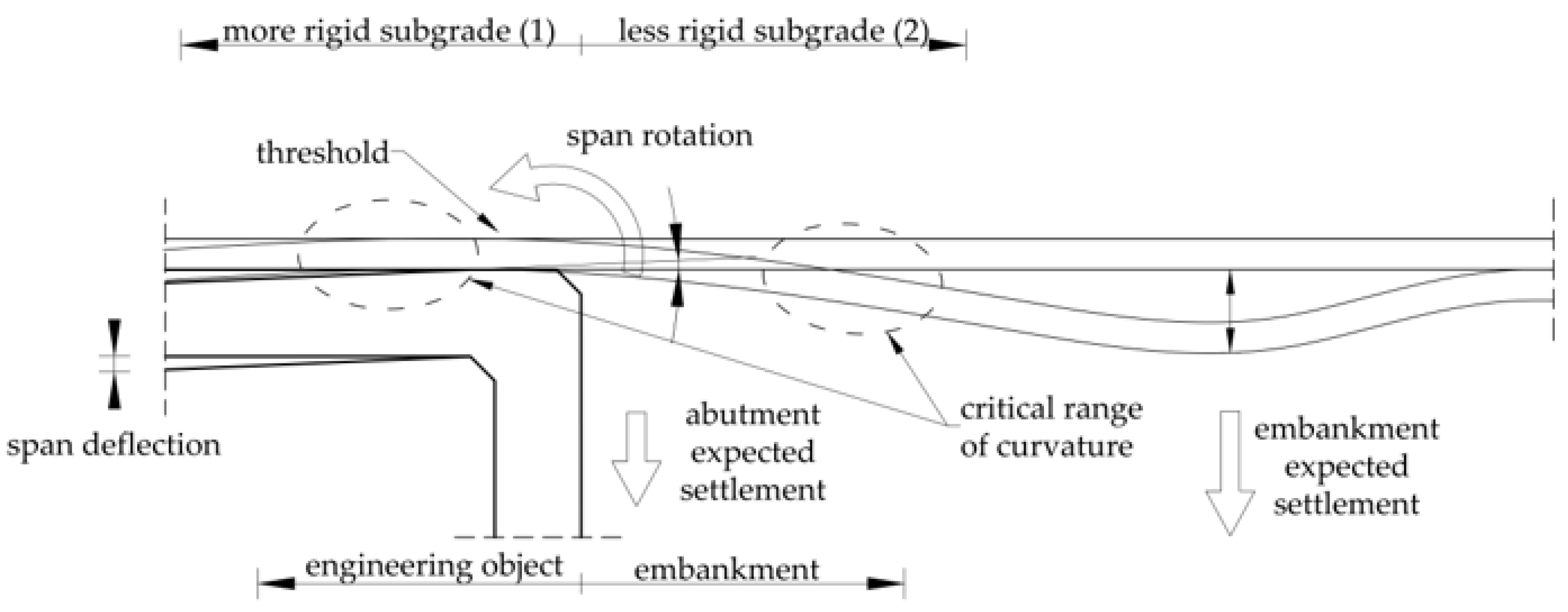
Figure 2.
3D model of an example integral bridge.
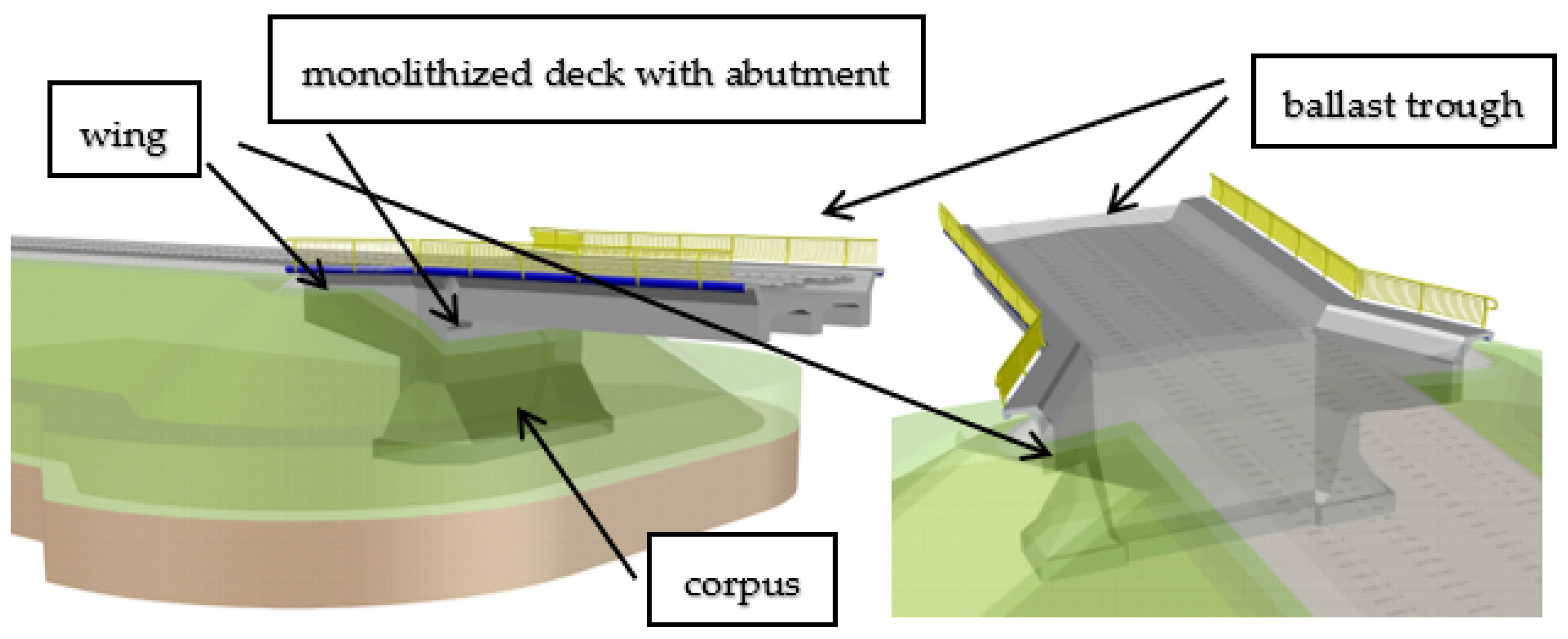
Figure 3.
Progress in the management of post-consumer plastic waste (EU27+3).
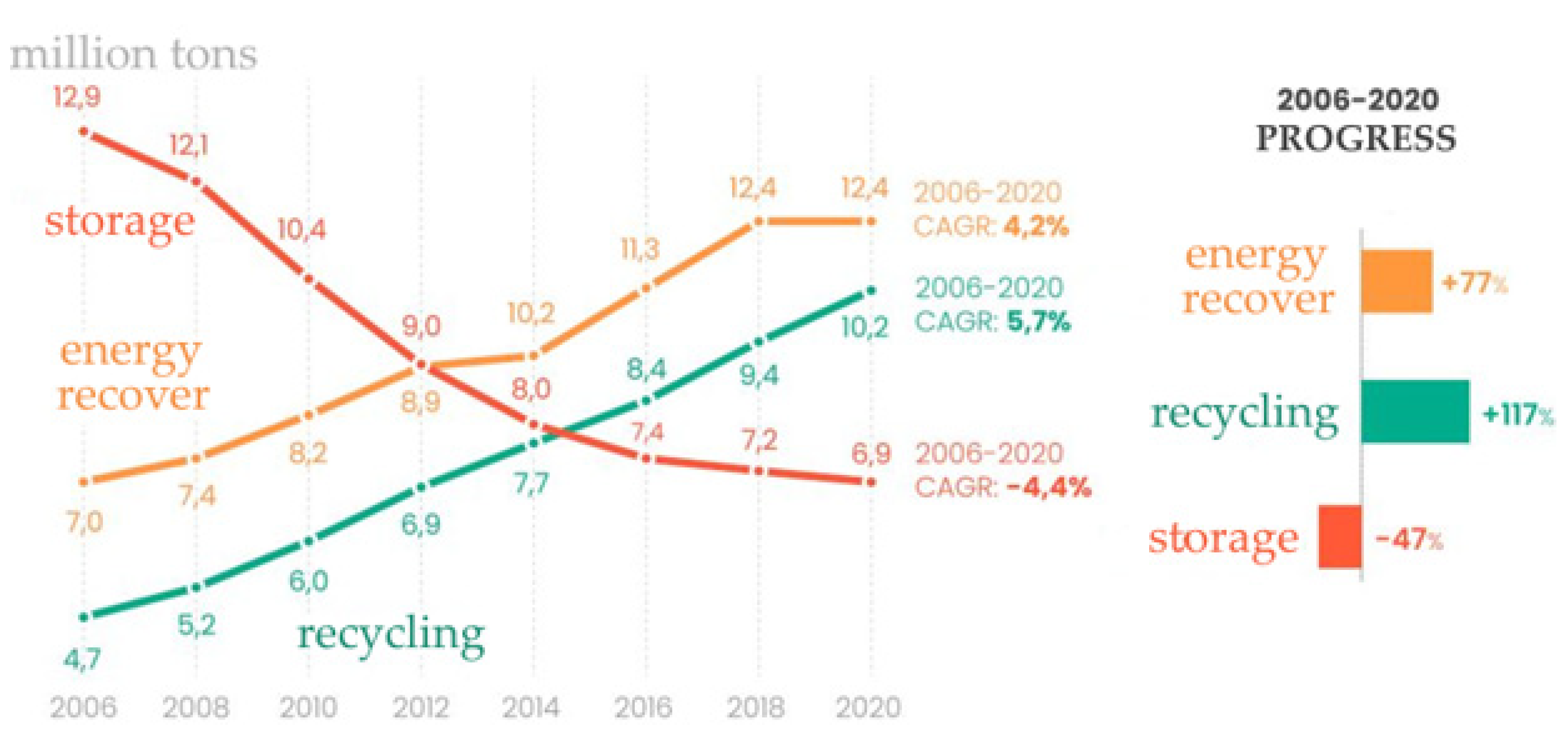
Figure 4.
Visualize the incidence and relationship of individual keywords created using VOSviewer showing additionally date of publication (accessed on 11.2023).
Figure 4.
Visualize the incidence and relationship of individual keywords created using VOSviewer showing additionally date of publication (accessed on 11.2023).
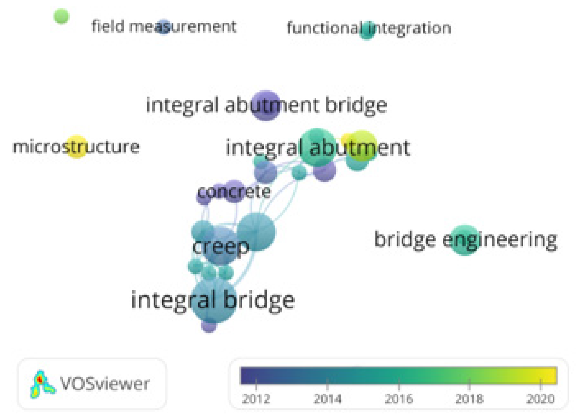
Figure 5.
Visualize the incidence and relationship of individual keywords created using VOSviewer showing additionally date of publication (accessed on 11.2023).
Figure 5.
Visualize the incidence and relationship of individual keywords created using VOSviewer showing additionally date of publication (accessed on 11.2023).

Figure 6.
Longitudinal section through an example of an integral abutment.
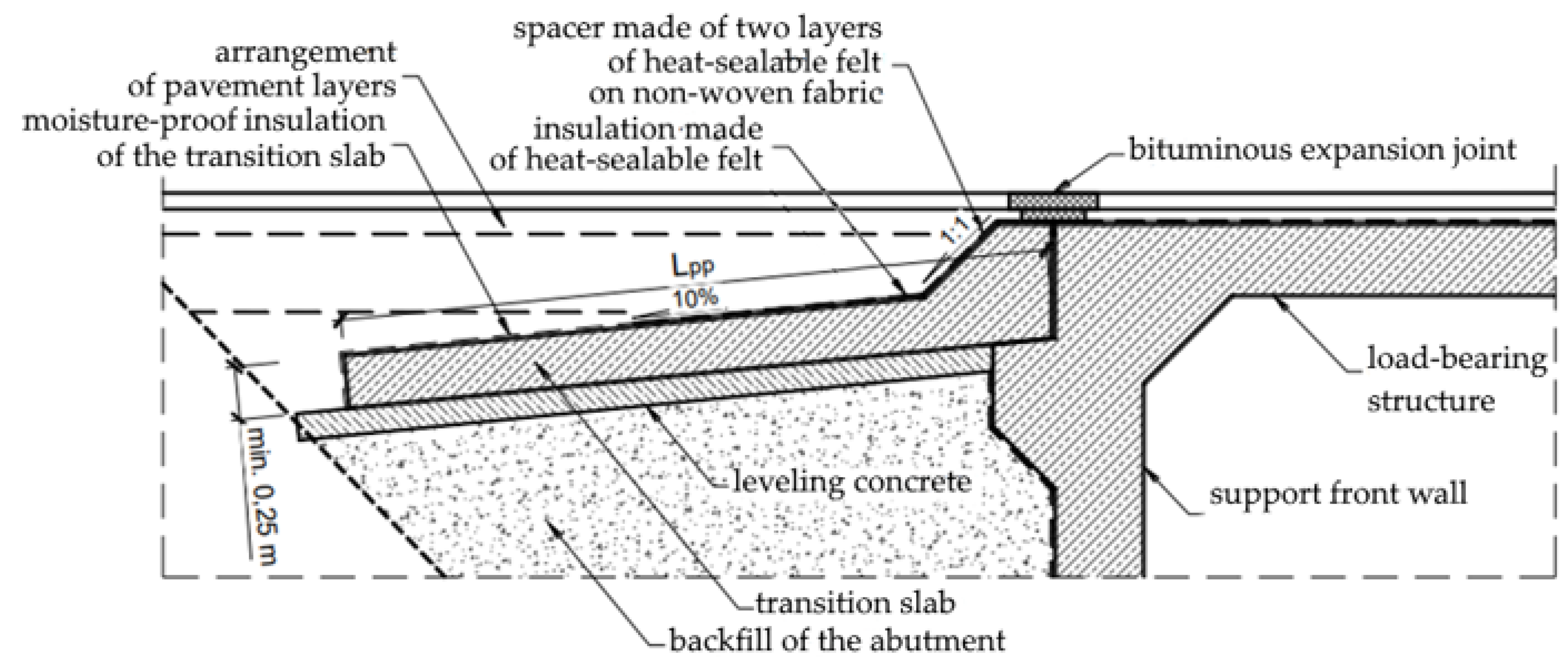
Figure 7.
Damage to road pavement and rail track superstructure at the beginning of the transition zone, where transition slabs were used.
Figure 7.
Damage to road pavement and rail track superstructure at the beginning of the transition zone, where transition slabs were used.
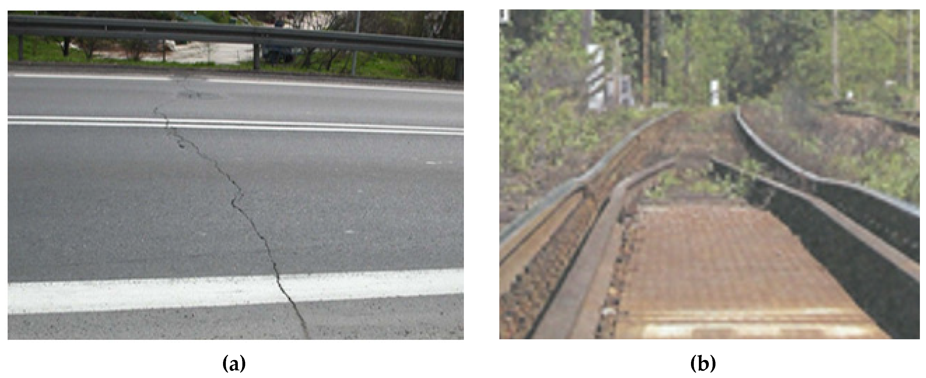
Figure 8.
Types of abutments.

Figure 9.
Structure of global plastics production.
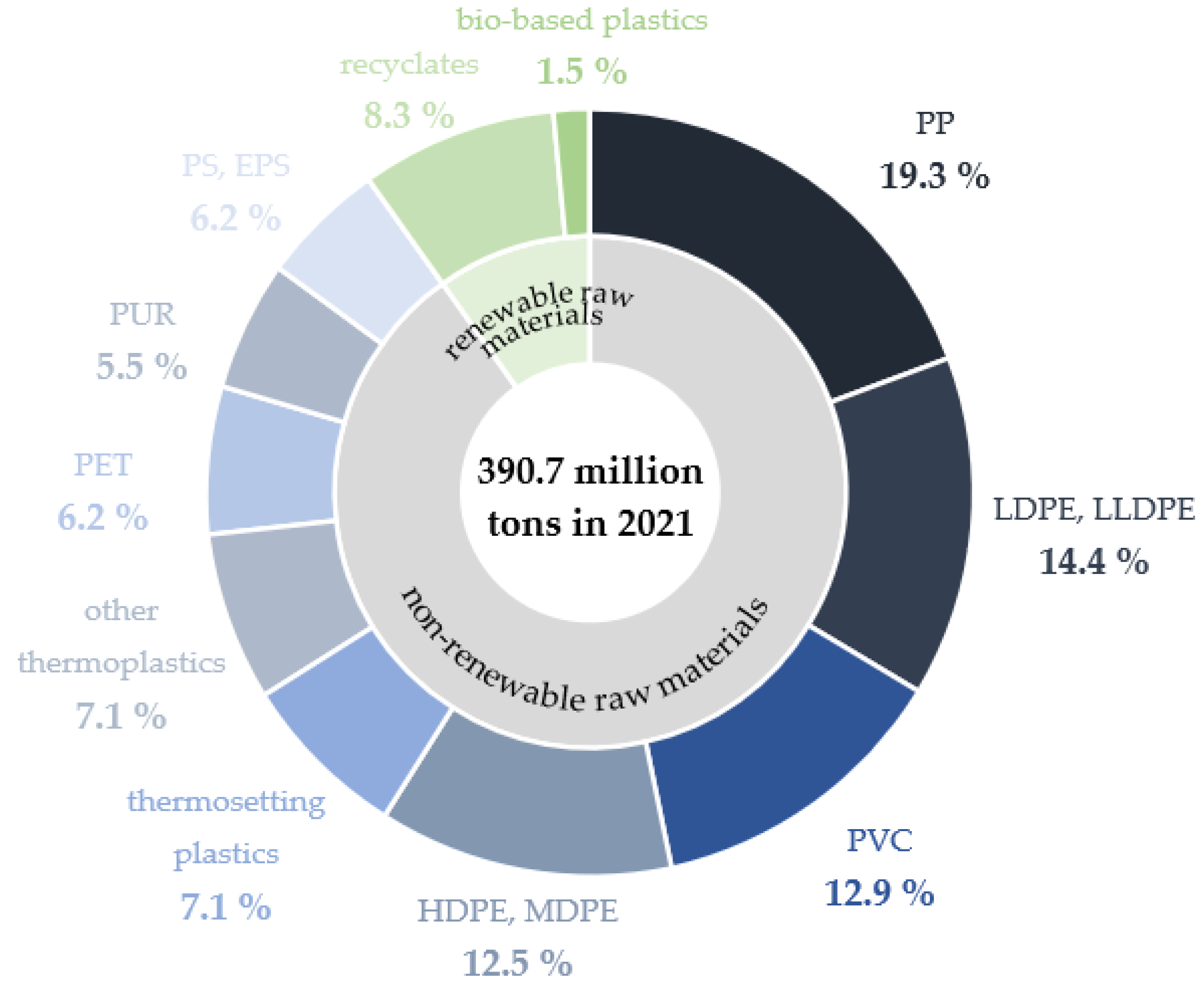
Figure 10.
A preliminary 3D model of the concept of a bar structure connecting the integrated bridge abutment with the embankment, forcing the cooperation of material centers.
Figure 10.
A preliminary 3D model of the concept of a bar structure connecting the integrated bridge abutment with the embankment, forcing the cooperation of material centers.
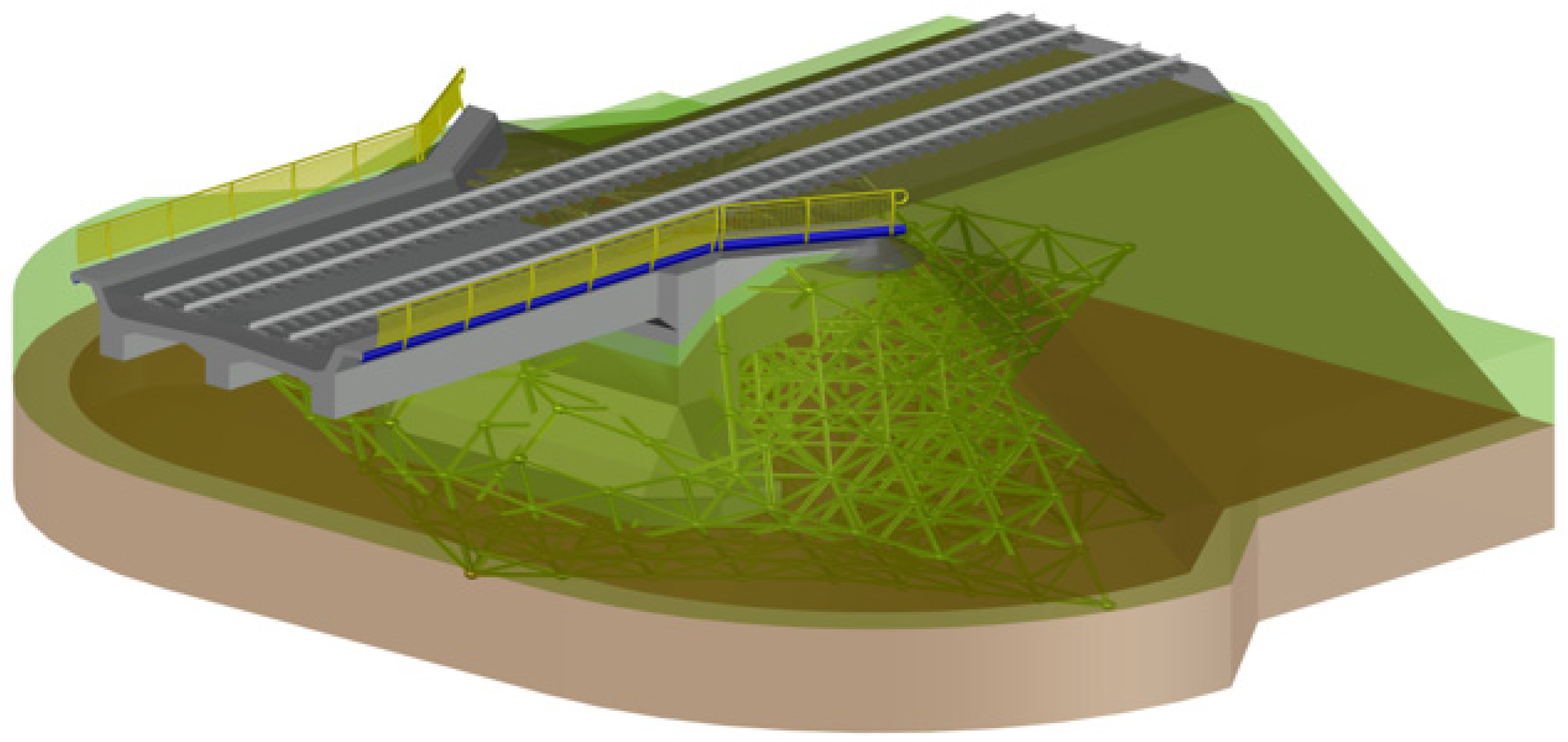
Figure 11.
A preliminary 3D model of the concept of a bar structure connecting the integrated bridge abutment with the embankment, forcing the cooperation of material centers.
Figure 11.
A preliminary 3D model of the concept of a bar structure connecting the integrated bridge abutment with the embankment, forcing the cooperation of material centers.
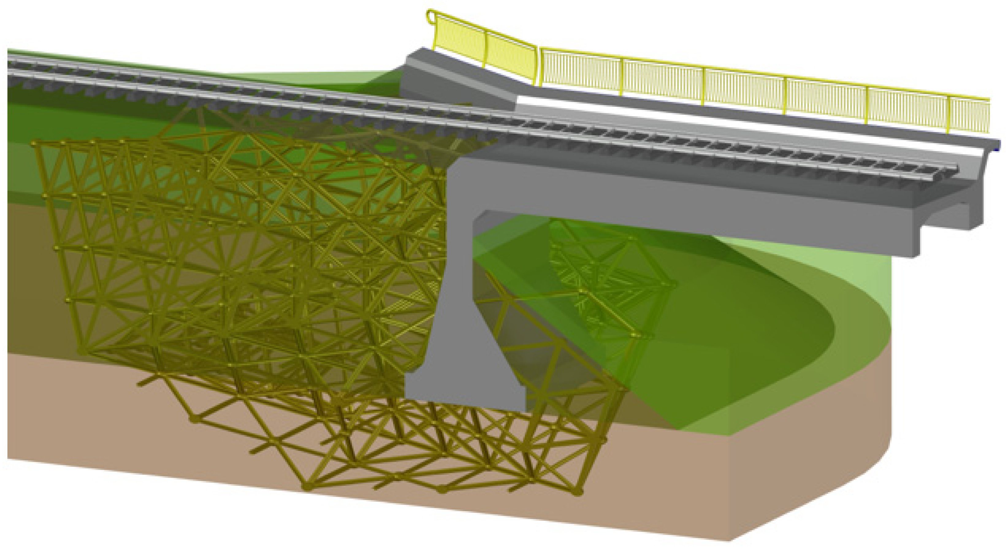
Figure 12.
The origins of the grid concept.
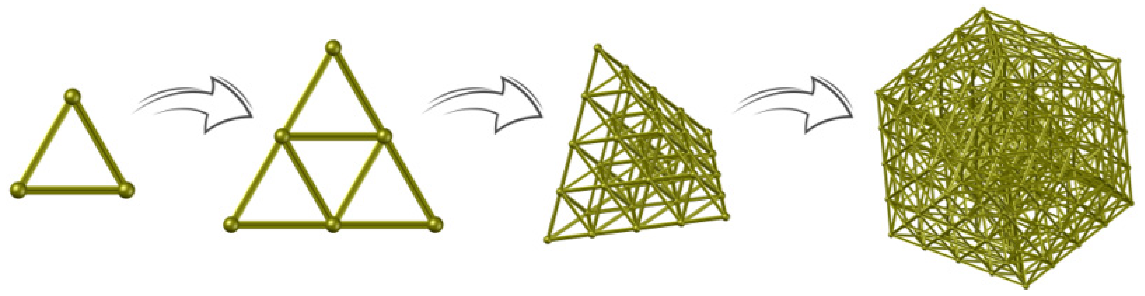

Table 1.
Dependence of the volume of the embankment depending on its height per 1 m.
| height of the embankment [m] | narrow embankment for a single-track line [m3/mb] | narrow embankment for a double-track line [m3/mb] |
|---|---|---|
| 3 | 19.47 | 19.90 |
| 5 | 36.25 | 36.68 |
| 8 | 70.03 | 70.46 |
| 12 | 131.18 | 131.61 |
| 20 | 308.67 | 309.10 |
Table 2.
Keyword association results summary.
| selected keywords | number of searches by | ||
|---|---|---|---|
| Scopus | Web of Science | ||
| civil engineering | 1 | 1,748,102 | 1,057,904 |
| integral bridges | 6,195 | 5,314 | |
| transition zone | 75,613 | 65,590 | |
| transition effect | 593,443 | 476,006 | |
| reinforced polymer composite | 56,775 | 57,048 | |
| recycling | 245,488 | 240,686 | |
| civil engineering + integral bridges | 2 | 149 | 1,000 |
| integral bridges + transition zone | 9 | 10 | |
| integral bridges + transition effect | 50 | 64 | |
| reinforced polymer composite + recycling | 1,515 | 2,049 | |
| civil engineering + integral bridges + transition zone | 3 | 0 | 5 |
| civil engineering + integral bridges + transition effect | 0 | 7 | |
| transition zone + transition effect + reinforced polymer composite |
40 | 51 | |
| transition zone + reinforced polymer composite + recycling |
4 | 10 | |
| integral bridges + transition zone + transition effect + recycling |
4 | 0 | 0 |
| civil engineering + transition zone + transition effect + recycling |
5 | 320 | |
| integral bridges + transition zone + transition effect + reinforced polymer composite + recycling |
5 | 0 | 0 |
| civil engineering + integral bridges + transition zone + transition effect + reinforced polymer composite + recycling |
6 | 0 | 0 |
Table 3.
Comparison of the properties of reinforced recycled polymers to steel.
| material | tensile strength | density | real strength |
|---|---|---|---|
| [-] | [MPa] | [g/cm3] | [kNm/kg] |
| PET reinforced with glass fiber in a ratio of 55 % |
196 | 1,80 | 108,9 |
| PET reinforced with carbon fiber in a ratio of 30% |
220 | 1,45 | 151,7 |
| Steel S235JR | 360 - 510 | 7,85 | 45,9 - 65,0 |
| Steel S355 | 470 - 630 | 7,85 | 59,9 - 80,3 |
Disclaimer/Publisher’s Note: The statements, opinions and data contained in all publications are solely those of the individual author(s) and contributor(s) and not of MDPI and/or the editor(s). MDPI and/or the editor(s) disclaim responsibility for any injury to people or property resulting from any ideas, methods, instructions or products referred to in the content. |
© 2024 by the authors. Licensee MDPI, Basel, Switzerland. This article is an open access article distributed under the terms and conditions of the Creative Commons Attribution (CC BY) license (http://creativecommons.org/licenses/by/4.0/).
Copyright: This open access article is published under a Creative Commons CC BY 4.0 license, which permit the free download, distribution, and reuse, provided that the author and preprint are cited in any reuse.


