Submitted:
17 December 2023
Posted:
18 December 2023
You are already at the latest version
Abstract
In a Water-Cooled Lithium-Lead (WCLL) Breeding Blanket (BB), the heat generated by the plasma thermal radiation and nuclear reactions is removed mainly by two components; namely, the First Wall (FW) and the Breeding Zone (BZ). The FW faces the neutrons and charged particles fluxes generated by the fusion reactions and the thermal radiation coming from the plasma. The present work takes into account the FW cooling system inspired by the WCLL BB 2018 design of DEMO 2017 baseline. Unlike the baseline where a Pressurized-Water Reactor (PWR) setup is used for the coolant, various setup between the Boiling Water Reactor (BWR) and the High-Pressure (HP) BWR are studied in the present work operating in the Two-Phase Flow (TPF) regime. The 3D model of the FW in the WCLL BB 2018 design is simplified into a 1D model and a steady state analysis is carried out to optimize the mass flow rate of the water and the number of parallel channels at the BB cells at different poloidal locations of the reactor, which helps not only in reducing the used coolant but also in improving the Tritium Breeding Ratio (TBR). The present work takes into account forced convection in the liquid only region, the subcooled boiling region, and the saturated boiling region using suitable empirical or semi-empirical models from the literature. The results are validated against the existing results in the literature. In the end, related conclusions are made regarding the pros and cons of the studied operating conditions.
Keywords:
Water-cooled Lithium-Lead
; breeding blanket
; first wall
; pressurized water reactor
; boiling water reactor
; steady state
; poloidal locations
; Tritium Breeding Ratio
; subcooled boiling
; saturated boiling
1. Introduction
From the recent advancements in the field of fusion energy, it is evident that nuclear fusion reactors are going to play a vital role in the much-needed green energy revolution. The Breeding Blankets (BB) are the key components in the core of a fusion reactor, responsible for tritium breeding self-efficiency, ensuring an adequate neutron shielding and collecting almost 80% of the fusion power, which can be used for electricity or hydrogen production. The Water-Cooled Lithium-Lead (WCLL) BB is a potential candidate for the DEMO fusion power plant ([1,2]). It adopts Lithium Lead (PbLi) as the breeder, tritium carrier and neutron multiplier, and Eurofer as the structural material. Water is used as coolant for the First Wall (FW). The design of WCLL BB is in accordance with the Single Module Segment (SMS) approach, which is based on DEMO 2017 baseline. This design is divided in 16 equal sectors in the toroidal direction. The DEMO 2017 baseline design takes into account the coolant water under pressurized condition at typical pressurized water reactor (PWR) setup, which transfers the heat to a secondary circuit through a primary heat transfer system (PHTS) [1].
Among the disadvantages of using water as the coolant is the dependency of the Tritium Breeding Ratio (TBR) on the moderation effect of water on the neutrons [3]. In the design of DEMO fusion reactor, this results in the need of the optimization of water mass flow rate and the number of cooling channels to reduce the exposure of neutrons to the water. In a study by Edemetti et al. [4], the number of channels in the FW of the BB are optimized and the results are presented for a typical PWR operating conditions using a 3D CFD analysis of the FW with keeping the temperature of the structural material under desired limits. From the analysis by Edemetti et al. [4], it is found that the critical heat flux is comfortably higher than the maximum heat flux provided to the parallel channels alongside a reasonable temperature of the Eurofer material compared to the limits. This makes the scope of further optimization of the mass flow rate in the channels, but the possibility of the existence of subcooled boiling at the exit of the channel might indicate that the further reduction in mass flow rate would result in a high increase in the volume of the PHTS.
To further reduce the mass flow rate, it is proposed to operate the coolant fluid in a Boiling Water Reactor (BWR) setup, where the secondary loop operating at a low pressure is eliminated. The use of a BWR setup eliminates the need of PHTS and allows a high-quality coolant at the exit of the core of the reactor at the saturation temperature. The possibility of higher quality at the exit of the FW allows for a lower mass flow rate (by means of an increase in the overall power to mass flow rate ratio) and a reduced number of channels in the FW.
The operating condition of a standard BWR are well known in the literature and is a good candidate for the present study. Alongside the standard BWR operating condition, the concept of High-Pressure (HP) BWR is studied as well in the literature [5]. A detailed analysis by Reisch [5] shows that such a reactor concept is promising in future not only from the point of view of overall efficiency but also for the implementation. Therefore, in the present work, the operating conditions between the standard BWR and HP BWR are studied for the optimization of the water mass flow rate and the number of channels in the FW.
With the introduction of the BWR and HP BWR setup and the elimination of the secondary coolant loop, the activity of the water becomes an important concern. There have been various studies comparing the activity of water in fusion and fission reactors ([6,7]). The neutrons in a fusion reaction contain much higher energy than the neutrons generated in a fission reaction. A study by Zohar et al. [6] shows for a same cross section that the O16 and O17 isotopes are more activated in the fusion reaction compared to a fission reaction but the O18 isotope activates in a same order as in a fission reaction. In the present work, the activity of these isotopes is considered acceptable, and the focus is kept on the thermal hydraulic performance of the FW.
A 1D flow model is developed to study the thermohydraulic of the FW at steady state. An attempt is made to explore the operating conditions other than the baseline to optimize the mass flow rate and number of channels in the FW of the WCLL BB 2018 design. In the end, a detailed analysis is carried out to understand the results and discuss the future developments.
The present paper is structured as follows:
- In section 2, the WCLL BB 2018 FW design and specifications of the DEMO 2017 baseline for the considered poloidal positions are reported.
- In section 3, the mathematical model and correlations adopted to simulate the flow of water in the FW are listed.
- In section 4, the present modelling approach is validated against the available results.
- In section 5, the results for the various case studies are presented and analyzed (under a grid independence test).
- In section 6, the conclusions based on the present study are made and a discussion is carried out regarding the future developments of the present work.
2. DEMO WCLL 2018
In DEMO WCLL 2018 BB, each toroidal sector of the reactor consists of different kinds of BB cell designs specific to the related poloidal positions. In different BB designs over the time, the number and design of these BB cells in the poloidal direction have changed ([8,9]). These cells are generally categorized in two kinds, the Central Outboard Segment (COB) and the Inboard Segment (IB). In the present work, three different kinds of poloidal positions and the related BB cells are considered and studied. One of these three cells is the COB equatorial cell whereas the rest two cells are in the IB Segment.
2.1. DEMO WCLL 2018 BB baseline design
Every BB cell in the DEMO WCLL 2018 consists of the FW and the Breeding Zone (BZ). The FW is the external structure made of Eurofer material, which is cooled by counter currently flowing water channels with a Tungsten armor that faces the heat flux from the plasma. The BZ is the internal structure filled with the liquid PbLi alloy. The FW is an important component for heat extraction since the Tungsten armor directly faces the heat flux coming from the plasma.
The FW system is external to the BZ taking a U-shaped structure with a thickness of 25 mm. This structure starts with the radial direction and then bends towards the toroidal direction and then bends again towards the radial direction. The plasma facing part of the FW is coated with a 2 mm thick Tungsten armor. The coolant water flows counter currently inside the parallel channels of a common dimension 7 x 7 mm. In the baseline design, the water operates at 15.5 MPa i.e., at a typical PWR operating condition and removes the heat flux from the FW.
The present work takes into account three different kinds of cells at different poloidal locations as used in Edemetti et al. [4] with the related geometrical specifications listed in Table 1. The number of channels for a BB cell in the present work is optimized starting from 10 to 1 for all the cases. In Figure 1, one such case is shown such that a COB BB cell can have 10, 6 or 4 parallel channels by changing the pitch of the channels.
2.2. DEMO thermal loads
For a steady state analysis, the reactor is considered to be working at the stationary full power in the flat-top phase. The thermal loads in the WCLL BB occur by several thermal sources. The fusion reaction generates power in form of neutron and charged particles fluxes and the radiation caused by the hot plasma. These power sources can be assumed constant during a steady state operation and can be categorized mainly in two parts: first, the volumetric power density in the material due to interaction of the neutrons and the Tungsten armor, and second, the heat flux to the Tungsten armor caused by the charged particles and the thermal radiation.
In general, the FW and the BZ are parts of a BB cell and coupled, but for sake of simplicity and to independently analyze the FW cooling system, the interaction of FW and BZ is neglected. The DEMO reactor is not symmetric so that, the thermal loads due to both the categories differ from each other at all the three considered poloidal positions. The volumetric power generation or the heating due to neutron and Tungsten armor interaction for the COB and IB cells are taken from Noce et al. [8]. For the IB apical BB cell, the volumetric power generation is computed using the Neutron wall load (NWL) as suggested in Edemetti et. al. [4]. On the other hand, the heat flux for different BB cells is used as defined by Maviglia et. al. [9]. It is to be noted that in Noce et al. [8], a toroidal sector is subdivided in 7 IB and 7 COB modules, whereas in Maviglia et al. [9], a toroidal sector is subdivided in 12 IB and 18 COB modules as shown in Figure 2. In present work, the contribution of the volumetric power generation and the heat flux thermal loads is listed with the module to which they belong in the aforementioned studies in Table 2.
2.3. DEMO thermal loads
In the baseline WCLL BB cells, typical PWR operating conditions are incorporated to deliver the water at a maximum limit temperature to provide to the PHTS. In the present work, 4 different operating conditions are proposed and analyzed at 4 different system pressures as listed in Table 3. In all the cases, the inlet temperature of the coolant to the core is kept fixed at 486.6 K [5].
3. Modelling and formulation
In the present work, a 1D flow approach is used to study the thermohydraulic of the flow channels. The 3D sketch shown in Figure 1 is simplified to a 1D scheme as shown in Figure 3 being the details of the flow and thermal fields on the channels cross-section irrelevant to the present study. A single flow channel is subdivided in 5 regions from A to E. The regions A and E are not provided with any thermal load whereas regions B and D are subject to incremental and decremental heat fluxes respectively as described by Edemetti et al. [4]. On the other hand, region C is provided with a constant heat flux equal to the maximum heat flux in the channel. The square shaped cross section of the channel remains constant through all the regions.
In addition to the assumptions and boundary conditions considered in Edemetti et al. [4], the following assumptions are taken in the present 1D study:
- Due to the high pressure, the pressure drop across the channel is negligible compared to the inlet pressure, hence constant pressure is assumed in the thermal analysis.
- The volumetric power generation and the heat flux are combined and uniformly supplied as heat fluxes to the wetted surface of the 10 channels.
- The walls of the channels which are made of Eurofer and Tungsten have negligible resistance compared to the convective resistance associated to the flow.
- Accordingly, only the thermal hydraulic analysis of a single channel is sufficient with a symmetry condition rather than two channels with symmetry as follows:
In the present work, a finite volume method is used to discretize the following steady state 1D energy conservation equation using an upwind scheme:
Here, and is the channel perimeter.
After a conversion in terms of temperature, the discretized equation looks as follows:
Here, denotes the wall temperature at the ith control volume. The reactor thermohydraulic is studied by modelling the different heat transfer regions separately. The value of the heat transfer coefficient (α) is computed by means of these models as follows:
3.1. Forced convection in liquid only state
The water enters the FW channels in a subcooled liquid state and undergoes forced convection as the thermal loads become non-zero. Starting from a subcooled liquid state, the heating leads the bulk and wall temperatures of the water to rise. The heat transfer in this flow regime is computed from the Dittus-Boelter correlation [10] as shown in Equation (1). This flow regime continues until the nucleate boiling begins at the walls of the channel. For the nucleate boiling to begin at the wall, the wall temperature must overcome the temperature at the onset of nucleate boiling (Ts,ONB). The Davis and Anderson model [11] with the Frost and Dzakowic correction [12] is adopted (Equation (4)) as suggested in [13].
It is to be noted that boiling starts due to the wall superheating before than the bulk flow achieves the saturation temperature. Hence subcooled boiling sets up.
3.2. Subcooled boiling
In this flow regime, the heat flux can be evaluated as a combination of the heat flux through convective heat transfer and through nucleate boiling [14]:
Here, denotes the heat flux due to nucleate boiling and has been studied widely in the literature ([14,15,16,17]). denotes the heat flux due to nucleate boiling at the ONB. Mostinski’s correlation [15] was chosen in this paper for both its simplicity and accuracy for pressurized water, as reported in [13]:
Where:
The function of reduced pressure is taken from the Palen [18] as follows:
Equation (5) is solved iteratively to find the wall superheating Ts – TSAT as the bulk temperature of the fluid increases towards saturation. Subcooled boiling lasts until the bulk temperature of the working fluid reaches the saturation temperature of the working fluid. Then saturated boiling takes place.
3.3. Saturated boiling and two phase forced convective heat transfer
The saturated flow region is characterized by a boiling dominated regime where the major heat transfer mechanism is nucleate boiling, followed by a convection dominated regime where boiling is gradually suppressed. In the literature, numerous papers deal with the subject ([19,20,21]). The present study takes into account the Kandlikar’s correlation [19] as a recent and reliable approach is reported in [22]:
Here:
- Convection number: ,
- Boiling number: ,
- Froude number (liquid only): ,
- is the liquid alone HTC, that is the HTC computed for the liquid flowing at the superficial velocity.
Coefficients C1-5 are empirical constants. Coefficient accounts for the fluid (for water it is unity). The horizontal layout of the channel is accounted for by the term This term is forced to become unity when the Frlo is more than 0.04. A thermodynamic equation of state is used to get the density and other thermodynamic properties of water at given pressure and temperature. The NIST REFPROP subroutine is used to incorporate the equation of state in the present model.
3.4. Critical Heat Flux
The critical heat flux (CHF) in the present work is calculated using the following correlation presented by Shah [23]:
Here, and are the CHF for the horizontal and vertical channels respectively. khor is a factor accounting for the effect of the channel being horizonal and calculated for the single phase and two-phase regions as described in [23]. It is to be noted that the heat flux in the present study is not a constant but changes along the length of the channel. To account for the effect of non-uniform heat flux in the vertical channel, is divided by a factor F as suggested by Bennett et al. [24]. Such a correction is calculated by dividing the maximum heat flux in the channel by the average heat flux in the channel. Due to the large range of applicable pressures, tube hydraulic diameters, tube lengths and mass flux, the is calculated using the Bowring’s correlation [25]:
The coefficients A, B and C are empirical and calculated as described in [25]. is the difference between the saturated liquid enthalpy and the subcooled liquid enthalpy at the inlet of the channels. It is to be noted that the correlations presented by Bennett et al. [24] and Bowring [25] are proposed for a round shaped tube but are assumed to be applicable in the present study case replacing the hydraulic diameter due to the lack of alternative approaches.
In the normal design conditions, the operation of water-cooled reactors is kept within the CHF case and therefore the post CHF scenarios are not required to be modelled.
4. Validation
The present model is validated against the Edemetti et al. [4], In particular, the first 6 steady state cases considered in the cited study as shown in Table 4 are considered for comparison. The geometrical and thermal load specifications are used as in Table 1 and Table 2 respectively.
The parity plots between the bulk temperature and the average Reynolds number of the water at the exit of the FW are shown in Figure 4 and Figure 5 respectively. It can be observed from the comparisons that a good agreement between the results obtained using the present simplified model and Edemetti et al. [4] is achieved. Since the present work takes into account a 1D modelling approach for the heated channels and ignored the heat transfer in the walls of FW, only the results for the cooling channels are considered for the comparisons.
Moreover, due to the 1D behaviour of the cooling channels, only the average properties of the flow over the cross section are compared and validated. However, due to the ability of the present model to take into account subcooled boiling, it is observed that due to the wall temperature overtaking the Ts,ONB (346.45 °C), subcooled boiling takes place.
Figure 6 shows the variation of bulk and wall temperatures against the axial location of the channel for case 5 in Table 4. It is observed in the results that Tb and Ts are equal in the region A of the channel because of the adiabatic flow. In region B, due to incremental heat flux, it is observed that both Tb and Ts increase. The latter increases much more rapidly than Tb, the increasing heat flux determines a build-up of the wall temperature under a constant heat transfer coefficient due to single-phase forced convection. It is observed at the end of region B that Ts increases stepwise due to the presence of a stepwise increment of the heat flux starting from region C. The temperatures Tb and Ts increase parallel to each other in region C because of the constant heat flux. Within region C, it is observed that Ts becomes equal to TSAT at point S and larger than Ts,ONB after point O, which indicates the beginning of the subcooled boiling region. After point O, despite a constant heat flux in region C, it is observed that Ts does not increase parallel to Tb but flattens relatively, because of the increasing heat transfer coefficient due to the nucleate boiling contribution. At the end of region C, it is observed that a sudden heat flux decrease results in a decrease in the Ts such that it becomes lower than Ts,ONB which suppresses subcooled boiling. In region D, the heat flux decreases continuously resulting in a further decrease in Ts. At the end, Ts becomes equal to Tb in the absence of heat flux in region E.
Similarly, for all the other cases in Table 4 except case 1, subcooled boiling is captured. Therefore, based on this observation, it can be said that the present simplified approach is able to capture the subcooled boiling in the system. Moreover, it is found that the nucleate boiling in the subcooled boiling region gets suppressed because of the decrease in wall temperature Ts due to the decrease in the heat flux. This phenomenon is not observed in the study by Edemetti et al. [4] because of the absence of two-phase flow modelling.
In summary, the proposed approach can reproduce the results of the analysis by Edemetti et al. [4] concerning the cross-section averages of the main flow quantities. Moreover, it shows that, increasing the system pressure may lead to subcooled boiling in the high-heat flux region, which is not accounted in single-phase flow simulations. Therefore, based on the present validation, it can be said that the present simplified methodology is good enough to analyze the FW thermohydraulic at steady state and can be used to optimize the mass flow rate and number of channels for a BWR like or any other operating condition within the range allowed by the correlations.
5. Results
In the present work, 4 different kinds of operating conditions as listed in Table 3 are studied. For all the three different BB cells, all these 4 kinds of operating conditions are simulated and the related results are analyzed. For all the three kinds of BB cells and all the pressures, the inlet temperature of the water is fixed at 486.6 K (1) which lies well below saturation for all the proposed pressures. The mass flow rate in the FW is calculated by fixing the mass flow rate of the steam exiting the FW. This boundary condition helps in comparing the water mass flow rate needed at the inlet of the FW for different operating conditions. It is to be noted that the fixed steam mass flow rate can be different for different kinds of BB cells due to different heat fluxes and configurations. The proposed method adopts a finite volume method to solve the energy balance equation along the channel. Hence, a grid independence test is carried out to ensure the consistency of the results with the number of control volumes.
5.1. Grid independence test
To determine the optimum number of discretization nodes, a grid independence test is carried out. The case study chosen for the grid independence test is the COB equatorial cell 1 with 4 parallel channels at a typical standard BWR operating condition in order to consider all the heat transfer regions. An inlet temperature of 270°C is provided to the FW with a TSAT of 285.82°C. 9 different number of control volumes: 145, 290, 580, 1160, 1740, 2320, 2900, 3480, and 4060 are considered to compare the results. The axial locations in the channel where the subcooled boiling and the saturated boiling begin are plotted against the number of the control volumes in Figure 7. It can be observed that both the aforementioned axial locations become insensitive to a number of control volumes exceeding 1160.
In Figure 8, the quality of the water-vapor mixture at the exit of the FW is plotted against the number of control volumes. It can be observed again that the exit quality does not change significantly for a number of control volumes higher than 1160. Therefore, it is evident that 1160 control volumes are able to produce accurate enough and consistent results for the analysis in the present work.
5.2. FW COB equatorial cell results
The COB equatorial BB cell is simulated for various number of channels starting from 10 up to 1 in decreasing order. Since in the case of a standard BWR, an exit quality from the core is expected to be 0.15-0.30, the fixed mass flow rate of the steam at the exit of the FW for the COB equatorial cell is computed assuming a quality of 0.25 at the exit of the FW in the case with a system pressure of 70 bar and 4 number of channels. Accordingly, the mass flow rate of the steam at the FW exit is computed as 0.03646 kg/s for all the cases presented in this section.
At a pressure of 70 bar, the variation of Tb and Ts along the axial direction is shown in Figure 9 for different number of channels (nch). Regardless of nch, it is observed that Tb and Ts remain the same in the adiabatic regions A and E. In region B, Tb and Ts rise together with the latter increasing much more than the former under the forced convective heat transfer in the liquid only region. At the intersection of regions B and C, a stepwise heat flux variation is applied to the FW channels leading to a discontinuity in Ts. It can be observed that all the cases with different nch do not result in the same heat transfer region. The cases with nch = 10, 6 and 4 end up in the forced convection heat transfer liquid only: the temperature at the intersection of regions B and C is lower than Ts,ONB, whereas the cases with nch = 2 and 1 result in the subcooled boiling regime (temperature at the intersection of regions B and C higher than Ts,ONB). Almost in the middle of region C, Tb for all the cases with different nch attains the saturation temperature and saturated boiling onsets. It is to be noticed that the small step in all the cases at the transition from subcooled boiling to saturated boiling is an artifact due to the change in correlation adopted to calculate the heat transfer coefficient in both the regimes. At the boundary between regions C and D, there is a sudden drop in the heat flux leading the Ts to drop as well.
The heat transfer enhancement factor (ψ = α / αl) is reported for the same case study in Figure 10. It can be observed in the results that ψ remains 1 until the subcooled boiling starts. As expected, α increases as nch decreases due to the increase in the mass flow rate per channels. In the subcooled boiling region, a strong increase in ψ can be observed in all the cases. The peak located at the transition between subcooled and saturated boiling is artifact due to the change in the heat transfer model. As reported in Section 3, the selection of the boiling model is the subcooled boiling region has been done also with the aim of minimizing the artifact. In the saturated flow, it can be observed from the almost constant behavior of ψ that heat transfer is boiling dominated in all the cases because of the low quality of the vapor at the exit of the FW. This would make the system undergo a DNB if the maximum heat flux provided to a channel exceeded the CHF.
The various results for the heating of COB equatorial FW are reported in Table 5 for different system pressures and different number of channels.
It can be observed that the water mass flow rate to the FW increases with a decrease in the number of channels for all the system pressures because of the increased volumetric power (due to more Eurofer material in the FW). Among the different system pressures, it is observed that the water mass flow rate needed for the heat removal decreases with the increase in the system pressure which indicates that irrespective of the number of channels, high pressure BWR operating condition requires lesser amount of water mass flow rate. For all the system pressures, it is observed that the FW exit quality lowers with a decrease in the number of channels. On the other hand, the exit quality grows with increasing the system pressure. One of the reasons behind this behaviour is that due to a decrease in the mass flow rate, the quality at the exit of FW has to be higher in order to maintain the same mass flow rate of the steam at the exit. With an increase in system pressure for same number of channels, it can be observed that the length needed to reach the ONB and saturated boiling increases because of highly subcooled liquid at the inlet of the FW.
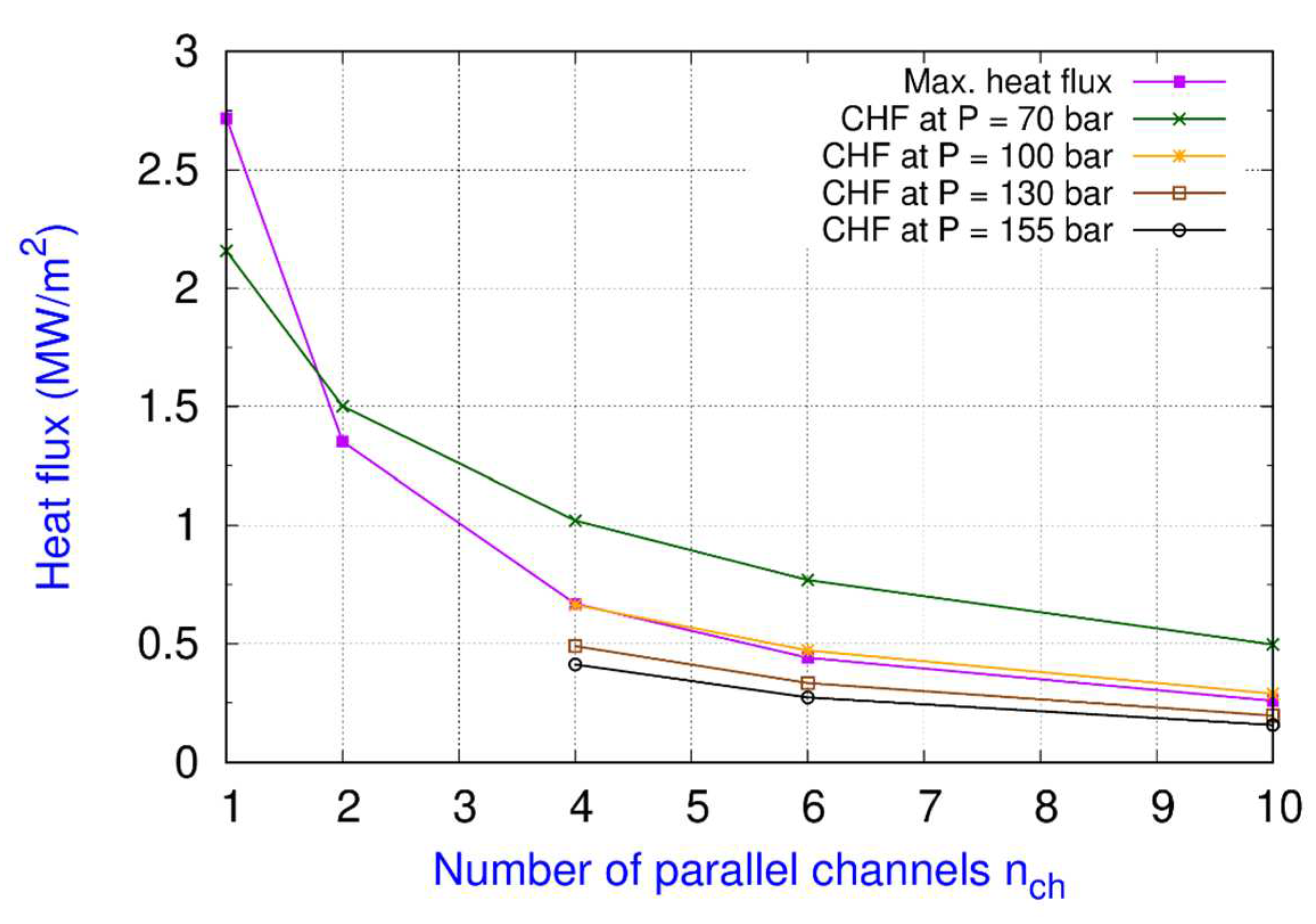
The comparison between CHF and maximum heat flux supplied to a FW channel for all the cases listed in Table 5 is shown in Figure 11. It can be observed from the results, that for a pressure of 70 bar, all the number of channels except for 1 show safe operation of the system. At a pressure of 100 bar, the operation is close to CHF, which is always exceeded at higher pressures. It is interesting to notice that the horizontal layout introduces a significant penalization: the factor khor (Table 5) shows values around 0.7-0.8 which makes the CHF much lower than for a vertical channel.
It should be noted that the FW channels undergo CHF for the desired exit mass flow rate of steam but it is possible to operate the FW at these high pressures at a lower mass flow rate of steam at the FW exit. For the case with system pressure of 100 bar and 4 channels, a steam mass flow rate of 0.0359 kg/s (exit quality = 0.296) can be obtained without the CHF. For the system pressure of 130 bar and number of channels 10, 6 and 4, the steam mass flow rate at FW exit of almost 0.0077 kg/s can be obtained without reaching CHF. Similarly, for a system pressure of 155 bar and number of channels 10, 6 and 4, the steam mass flow rate at FW exit of almost 0.0066 kg/s can be obtained without reaching the CHF.
Figure 12.
Comparison of the maximum heat flux supplied to a FW channel and the CHF for the cases reported in Table 5.
Figure 12.
Comparison of the maximum heat flux supplied to a FW channel and the CHF for the cases reported in Table 5.
5.3. FW IB cell results
The results for the heating of IB cell FW as described in Table 1 and Table 2 are reported in Table 6 for different system pressures and different number of channels. The fixed mass flow rate of the steam at the exit of the FW for the IB cell is computed by keeping a quality of 0.14 at the exit of the FW in the case with a system pressure of 70 bar and 4 channels. The mass flow rate of the steam at the FW exit is computed as 0.0168 kg/s for all the cases.
Observations analogous to the ones reported in the previous section hold as well. The water flow rate required for all the pressures at all the number of channels in the IB cell FW is found lesser than the COB equatorial cell FW because of lesser heat flux. The comparison of the CHF and maximum heat flux supplied to a FW channel for all the cases listed in Table 6 are shown in Figure 11. It can be observed that for a pressure of 70 bar all the number of channels except for 1 show safe operation of the system without the onset of CHF. For a system pressure of 100 bar, it is observed that the cases with 10, 6 and 4 number of channels show more CHF compared to the maximum heat flux given to the FW channel, but the cases with 2 or 1 number of channels show lower CHF than the maximum heat flux given to the FW channel and therefore undergoes DNB. For the system pressures of 130 bar and 155 bar, just like COB equatorial cell FW, it is observed that the CHF is less than the maximum heat flux irrespective of the number of channels for the desired mass flow rate of steam at the FW exit. At these high pressures, an exit quality more than 0.2 is observed but the FW channel undergoes DNB. In the case of IB cell FW, the mass flow rate is found to be lower than the COB equatorial cell FW which results in an even higher penalization in the CHF due to the horizonal layout. It can be observed from Table 6 that the factor khor values are close to 0.6-0.7, which are even lesser than 0.7-0.8 of the COB equatorial cell FW.
For the system pressure of 130 bar and number of channels 10, 6 and 4, a steam mass flow rate at FW exit of almost 0.0048 kg/s can be obtained without reaching CHF. Similarly for a system pressure of 155 bar and number of channels 10, 6 and 4, a steam mass flow rate at FW exit of almost 0.0042 kg/s can be obtained without reaching the CHF. For the system pressures of 130 and 155 bars, the exit quality comes out to be around 0.05.
5.4. FW IB apical cell results
The results for the heating of IB apical cell FW as described in Table 1 and Table 2 are reported in Table 7 for different system pressures and different number of channels. The fixed mass flow rate of the steam at the exit of the FW for the IB apical cell is computed by keeping a quality of 0.1 at the exit of the FW in the case with a system pressure of 70 bar and 4 number of channels. The mass flow rate of the steam at the FW exit is computed as 0.0566 kg/s for all the cases, which is considerably more than in COB equatorial and IB cells.
The observations reported in the Section 5.2 hold for the present section as well. The water flow rate required for all the pressures with all the number of channels in the IB apical cell FW is found almost 4 times the COB equatorial cell FW mass flow rate and almost 5 times of the IB cell FW because of the higher thermal radiation and charged particles flux on the Tungsten armor. The comparison of CHF and maximum heat flux supplied to a FW channel for all the cases listed in Table 7 and shown in Figure 13. It can be observed from the results, that for a pressure of 70 bar, all the number of channels except 1 show operation without DNB. For a system pressure of 100 bar, it is observed that the cases with 10 and 6 number of channels show more CHF than the maximum heat flux given to the FW channel, but the cases with 4 or lesser number of channels show lower CHF than the maximum heat flux given to the FW channel and therefore undergoes DNB. For the system pressures of 130 bar and 155 bar, just like the COB equatorial and IB cells FW, it is observed that the CHF is less than the maximum heat flux irrespective of the number of channels for the desired mass flow rate of steam at the FW exit. At these high pressures, an exit quality more than 0.15 is observed and the FW channel undergoes CHF. In the case of IB apical cell FW, the mass flow rate is found to be more than the COB equatorial and IB cell FW, which results in lesser penalization in the CHF due to the horizonal layout. It can be observed from Table 7 that the factor khor values are close to 0.8 more than 0.6-0.7 of IB cell FW or 0.7-0.8 of the COB equatorial cell FW.
For the system pressure of 130 bar with number of channels 10, 6 and 4, a steam mass flow rate at FW exit of almost 0.0207 kg/s can be obtained without reaching CHF. Similarly for a system pressure of 155 bar and number of channels 10, 6 and 4, a steam mass flow rate at FW exit of almost 0.0184 kg/s can be obtained without reaching the CHF. For the system pressures of 130 and 155 bars, the exit quality comes out to be around 0.05.
5. Conclusions
In present work, the DEMO WCLL BB 2018 baseline design FW was simplified to a 1D flow design and a steady state analysis was carried out to study the thermohydraulic of the FW system at the newly proposed operating conditions of the coolant water. Mainly 4 kinds of operating conditions at 4 different system pressure were proposed: 70 bar (BWR), 100 bar, 130 bar and 155 bar (HP BWR). The following conclusions can be made:
- Compared to a typical PWR operating conditions with the PHTS, the water mass flow rate for the same amount of heat removal and the same number of channels reduces by almost 3 - 5.5 times in the increasing order of system pressure for the all three kinds of BB FW considered in the present work.
- From thermohydraulic point of view, the number of channels in the FW can be at least 2 for the COB equatorial and IB cells and at least 4 for the IB apical cell at a typical standard BWR operating condition (70 bar).
- A significant reduction in the water mass flow rate and number of channels can help to maintain the required TBR.
- A significant reduction in the water mass flow rate results in a reduction of the contaminated fluid.
- The proposed operating conditions with system pressures of 70 bar is able to provide good and useful mass flow rate of steam at the exit of the FW with a safe operation far from the CHF.
- The proposed operating conditions with system pressures of 100 bar is able to provide a reduced mass flow rate of steam at the exit of the FW but with marginal safe operation from the CHF, whereas system pressures of 130 bar and 155 bar are able to provide much lesser mass flow rate of the steam at the exit of the FW compared to the 70 bar case with a safe operation away from the CHF.
- The horizontal layout seems the major cause for a reduced CHF. Actually, the CHF may lower up to 60% of the CHF for a vertical channel.
It is to be noted that the present work was intended to explore the various operating conditions which are not proposed in the conventional DEMO WCLL BB baseline design. The 1D flow approach allows to analyze the steady state thermohydraulic of the FW channels but includes some simplified assumptions and therefore provides a scope of future developments. One of these developments can be the consideration of the non-uniform heat flux around the perimeter of the channels, and the consideration of a constant total volumetric power generation in a BB cell regardless of the number of channels. Furthermore, a 3D model of the FW is useful to analyze the temperature distribution in the Eurofer structure and Tungsten armour. Eventually, the interaction of the BZ with the FW is another interesting potential area of research.
Author Contributions
Conceptualization: Vishal Garg; methodology: Vishal Garg; validation: Vishal Garg; formal analysis: Vishal Garg; investigation: Vishal Garg; resources: Vishal Garg and Luigi Pietro Maria Colombo; data curation: Vishal Garg; writing—original draft preparation: Vishal Garg; writing—review and editing: Igor Matteo Carraretto; visualization: Vishal Garg and Igor Matteo Carraretto; supervision: Luigi Pietro Maria Colombo. All authors have read and agreed to the published version of the manuscript.
Funding
This research received no external funding.
Data Availability Statement
Data sharing not applicable.
Conflicts of Interest
The authors declare no conflict of interest.
| Nomenclature | |||
| T | temperature, K | Greek letters | |
| P | pressure, bar | σ | surface tension, N/m |
| q” | heat flux, W/m2 | ρ | Density, kg/m3 |
| k | thermal conductivity, W/m-K | α | heat transfer coefficient, W/m2/K |
| h | specific enthalpy, J | Dimensionless numbers | |
| G | mass flux, kg/m2 | Re | Reynolds number |
| g | gravitational acceleration, m/s2 | Nu | Nusselt number |
| z | Axial coordinate, m | Co | Convection number |
| x | quality | Bo | Boiling number |
| Fr | Froude number | ||
| Pr | Prandlt number | ||
| Ψ | heat transfer enhancement factor | ||
| Subscripts | Acronyms | ||
| b | bulk | WCLL | Water cooled lithium lead |
| s | wall | BB | Breeding blanket |
| SAT | saturation | BWR | Boiling water reactor |
| ONB | onset of nucleate boiling | PWR | Pressurized water reactor |
| l | saturated liquid | PHTS | Primary heat transfer system |
| g | saturated gas | TBR | Tritium breeding ratio |
| lo | liquid only | FW | Front wall |
| cr | critical | BZ | Breeding zone |
| r | reduced | COB | Central outboard segment |
| CHF | critical heat flux | IB | Inboard segment |
| TP | two-phase | HF | Heat flux |
| sub | subcooling | ||
References
- G. Federici, L. Boccaccini, F. Cismondi, M. Gasparotto, Y. Poitevin, and I. Ricapito, “An overview of the EU breeding blanket design strategy as an integral part of the DEMO design effort,” Fusion Eng. Des., vol. 141, pp. 30–42, 2019. [CrossRef]
- T. Ihli et al., “Review of blanket designs for advanced fusion reactors,” Fusion Eng. Des., vol. 83, no. 7–9, pp. 912–919, 2008. [CrossRef]
- M. S. Tillack, P. W. Humrickhouse, S. Malang, and A. F. Rowcliffe, “The use of water in a fusion power core,” Fusion Eng. Des., vol. 91, pp. 52–59, 2015. [CrossRef]
- F. Edemetti, P. Micheli, A. Del Nevo, and G. Caruso, “Optimization of the first wall cooling system for the DEMO WCLL blanket,” Fusion Eng. Des., vol. 161, p. 111903, 2020. [CrossRef]
- F. Reisch, “High pressure boiling water reactor,” Nucl. Technol., vol. 172, no. 2, pp. 101–107, 2010. [CrossRef]
- A. Žohar, I. Lengar, and L. Snoj, “Analysis of water activation in fusion and fission nuclear facilities,” Fusion Eng. Des., vol. 160, p. 111828, 2020. [CrossRef]
- D. D. Macdonald, G. R. Engelhardt, and A. Petrov, “A critical review of radiolysis issues in water-cooled fission and fusion reactors: Part I, assessment of radiolysis models,” Corros. Mater. Degrad., vol. 3, no. 3, pp. 470–535, 2022. [CrossRef]
- S. Noce, F. Moro, F. Romanelli, and R. Villari, “Nuclear analysis of the single module segment WCLL DEMO,” Fusion Eng. Des., vol. 147, p. 111207, 2019. [CrossRef]
- F. Maviglia et al., “Wall protection strategies for DEMO plasma transients,” Fusion Eng. Des., vol. 136, pp. 410–414, 2018. [CrossRef]
- 10. W. H. McAdams, “Heat Transmission, McGraw-Hill,” New York, pp. 252–262, 1954.
- 11. E. J. Davis and G. H. Anderson, “The incipience of nucleate boiling in forced convection flow,” AIChE J., vol. 12, no. 4, pp. 774–780, 1966. [CrossRef]
- W. Frost and G. S. Dzakowic, “An extension of the method for predicting incipient boiling on commercially finished surfaces. ASME,” 1967.
- G. F. Hewitt and J. Barbosa, Heat exchanger design handbook, vol. 98. Begell house New York, 2008.
- A. E. Bergles and W. M. Rohsenow, “The determination of forced-convection surface-boiling heat transfer,” 1964.
- I. L. Mostinski, “Application of the rule of corresponding states for calculation of heat transfer and critical heat flux,” Teploenergetika, vol. 4, no. 4, pp. 66–71, 1963.
- V. K. Dhir, “Mechanistic prediction of nucleate boiling heat transfer–achievable or a hopeless task?,” 2006.
- D. Gorenflo, E. Baumhögger, G. Herres, and S. Kotthoff, “Prediction methods for pool boiling heat transfer: A state-of-the-art review,” Int. J. Refrig., vol. 43, pp. 203–226, 2014. [CrossRef]
- 18. J. W. Palen, “Shell-and-tube reboilers: Thermal design,” Handb. Heat Exch. Des., vol. 3, 1992.
- S. G. Kandlikar, “A general correlation for saturated two-phase flow boiling heat transfer inside horizontal and vertical tubes,” 1990.
- M. M. Shah, “A new correlation for heat transfer during boiling flow through pipes,” Ashrae Trans., vol. 82, no. 2, pp. 66–86, 1976.
- J. C. Chen, “Correlation for boiling heat transfer to saturated fluids in convective flow,” Ind. Eng. Chem. Process Des. Dev., vol. 5, no. 3, pp. 322–329, 1966. [CrossRef]
- W. M. Rohsenow, J. P. Hartnett, and E. N. Ganic, “Handbook of heat transfer applications,” 1985.
- 23. M. M. Shah, “A general correlation for critical heat flux in horizontal channels,” Int. J. Refrig., vol. 59, pp. 37–52, 2015. [CrossRef]
- A. W. Bennett, “Studies of burnout in boiling heat transfer to water in round tubes with non-uniform heating,” AERE-R5076, 1966.
- R. W. Bowring, “A simple but accurate round tube, uniform heat flux, dryout correlation over the pressure range 0.7-17 MN/m 2 (100-2500 PSIA),” UKAEA Reactor Group, 1972.
Figure 1.
WCLL FW design at COB equatorial (a) Top view and (b) Side view with different number of channels.
Figure 1.
WCLL FW design at COB equatorial (a) Top view and (b) Side view with different number of channels.
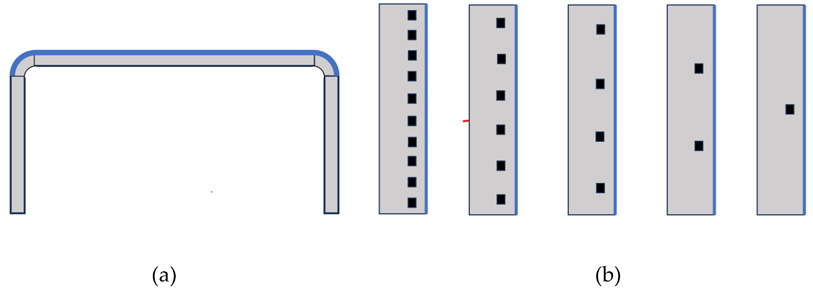
Figure 2.
BB models for the heat flux and volumetric power generation.
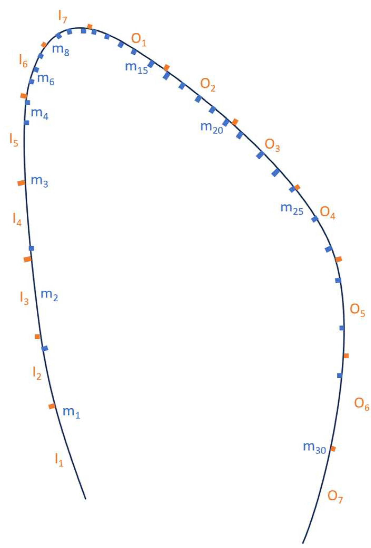
Figure 3.
A simplified scheme for a FW channel.
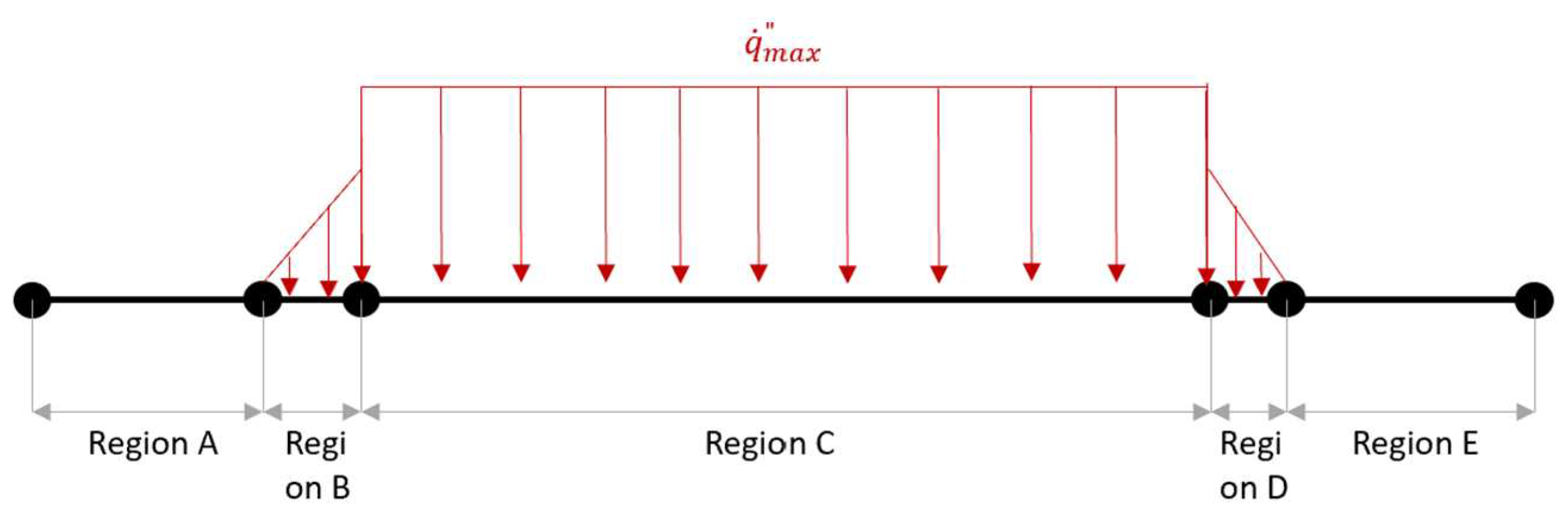
Figure 4.
Simplified parallel channels.
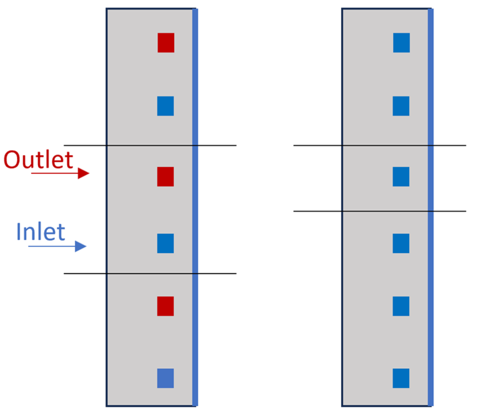
Figure 5.
Figure 5. Comparison of the temperature at the exit of FW between the present study and Edemetti et al. [4].
Figure 5.
Figure 5. Comparison of the temperature at the exit of FW between the present study and Edemetti et al. [4].
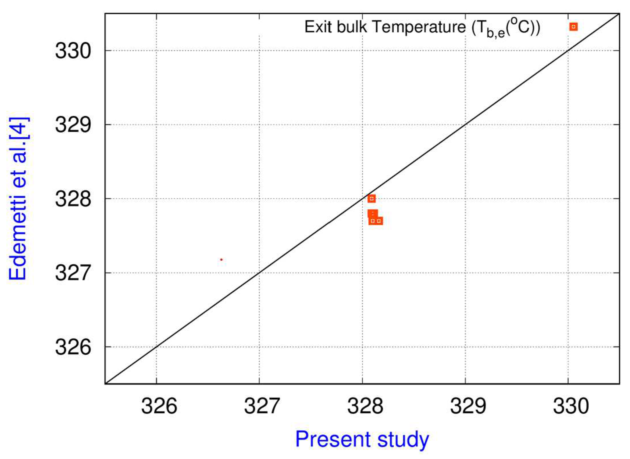
Figure 6.
Comparison of the average Reynolds number at the exit of FW between the present study and Edemetti et al. [4].
Figure 6.
Comparison of the average Reynolds number at the exit of FW between the present study and Edemetti et al. [4].
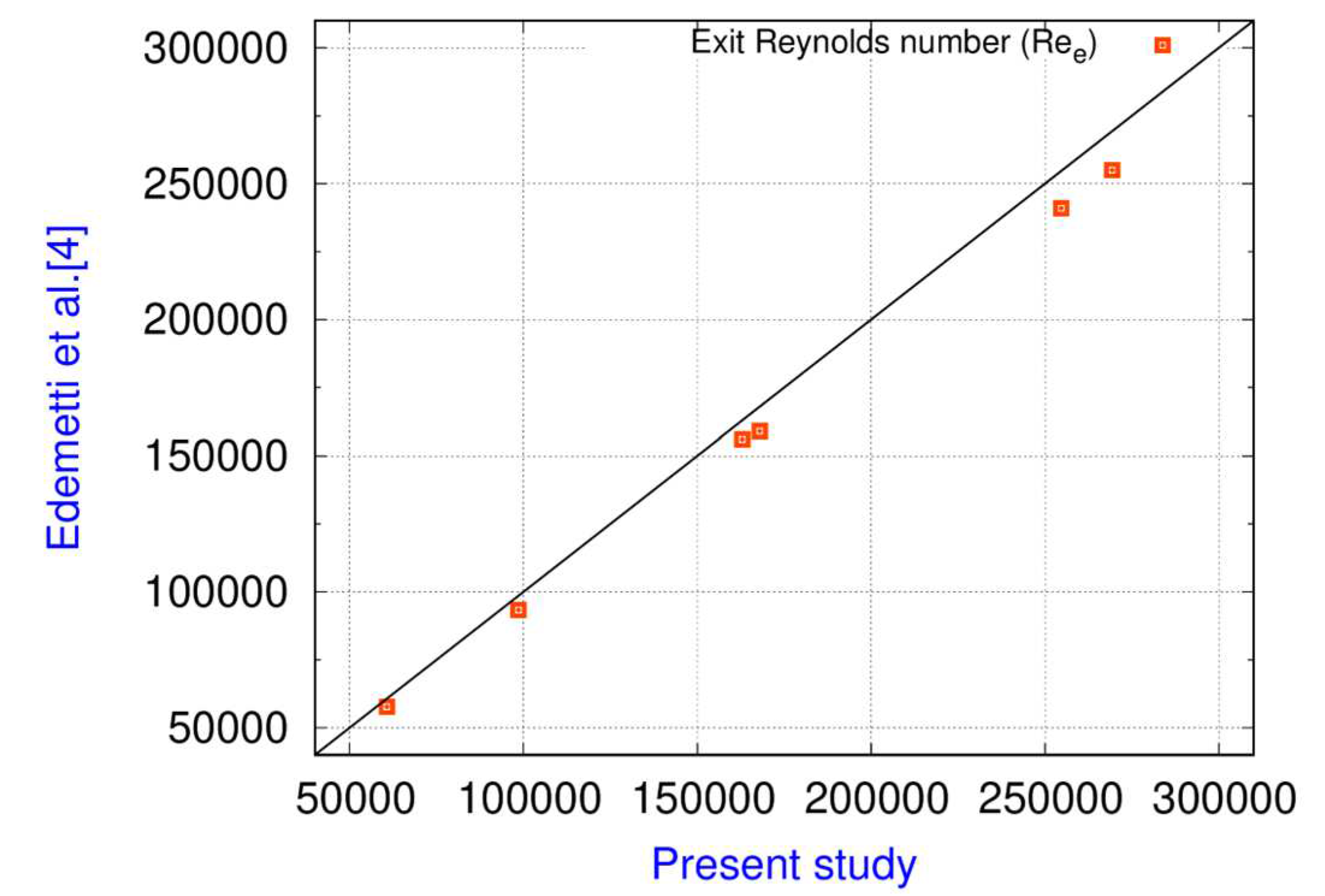
Figure 7.
Wall and bulk temperature distribution in the axial direction in the present study (Case 5 in Table 4).
Figure 7.
Wall and bulk temperature distribution in the axial direction in the present study (Case 5 in Table 4).
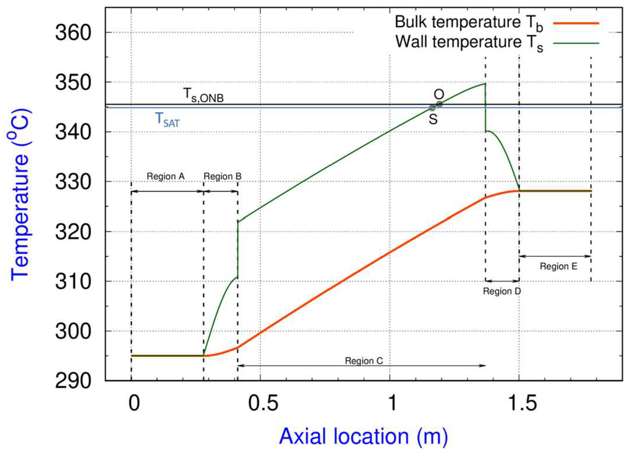
Figure 8.
Location of the subcooled boiling and saturated boiling onset against the number of control volumes.
Figure 8.
Location of the subcooled boiling and saturated boiling onset against the number of control volumes.
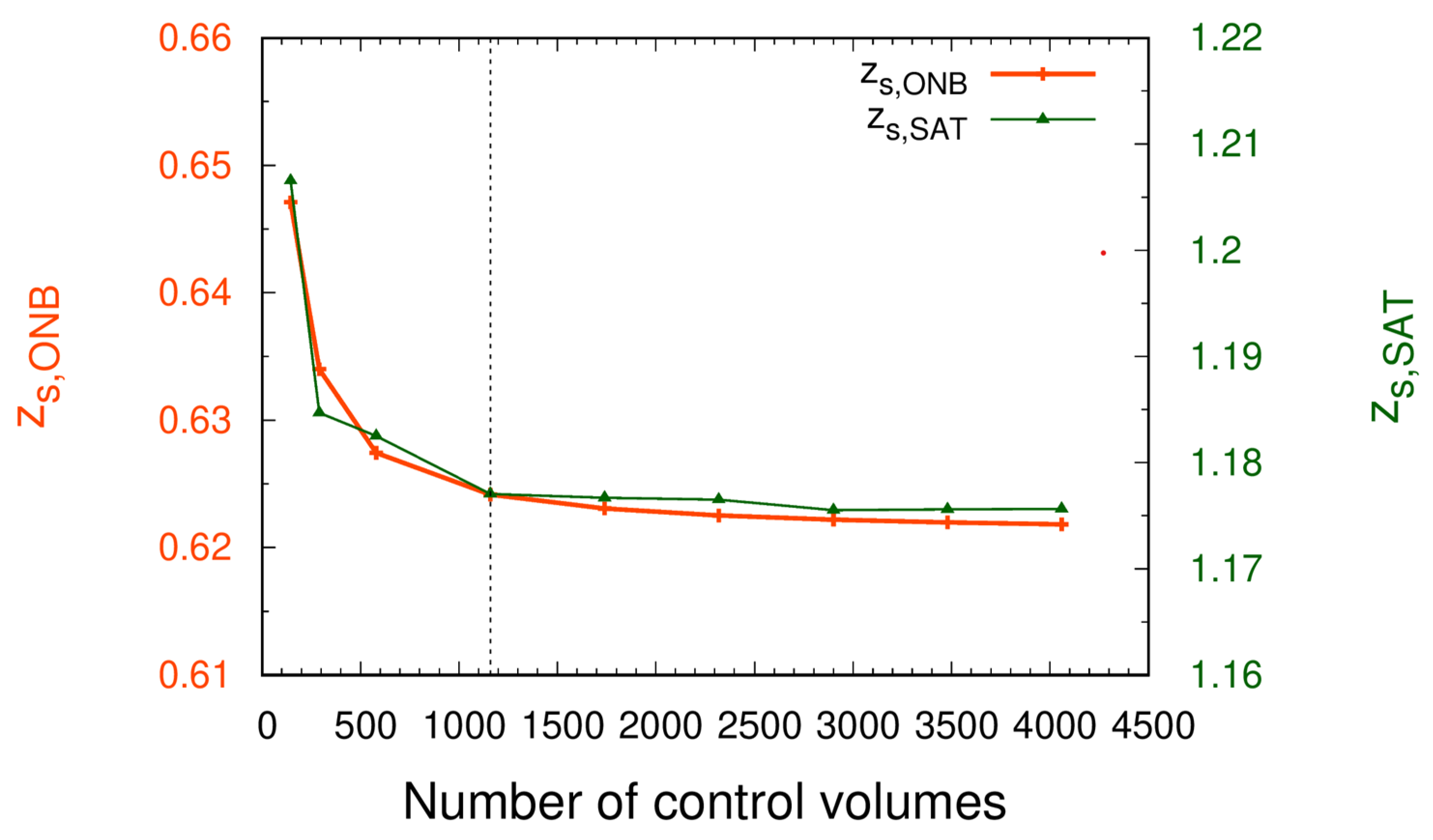
Figure 9.
FW exit quality against the number of control volume.
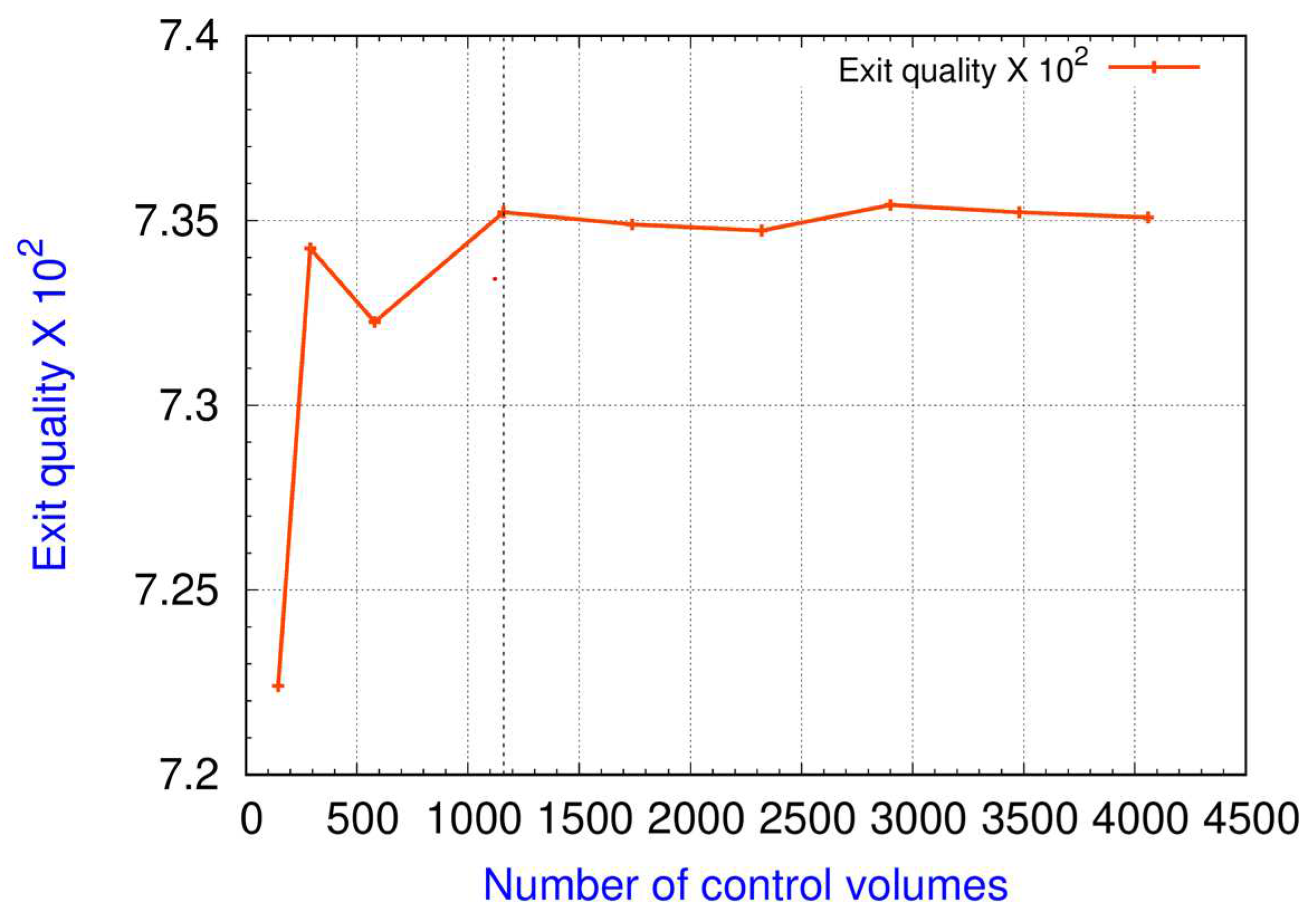
Figure 10.
Evolution of Tb and Ts with the axial location for different number of channels.
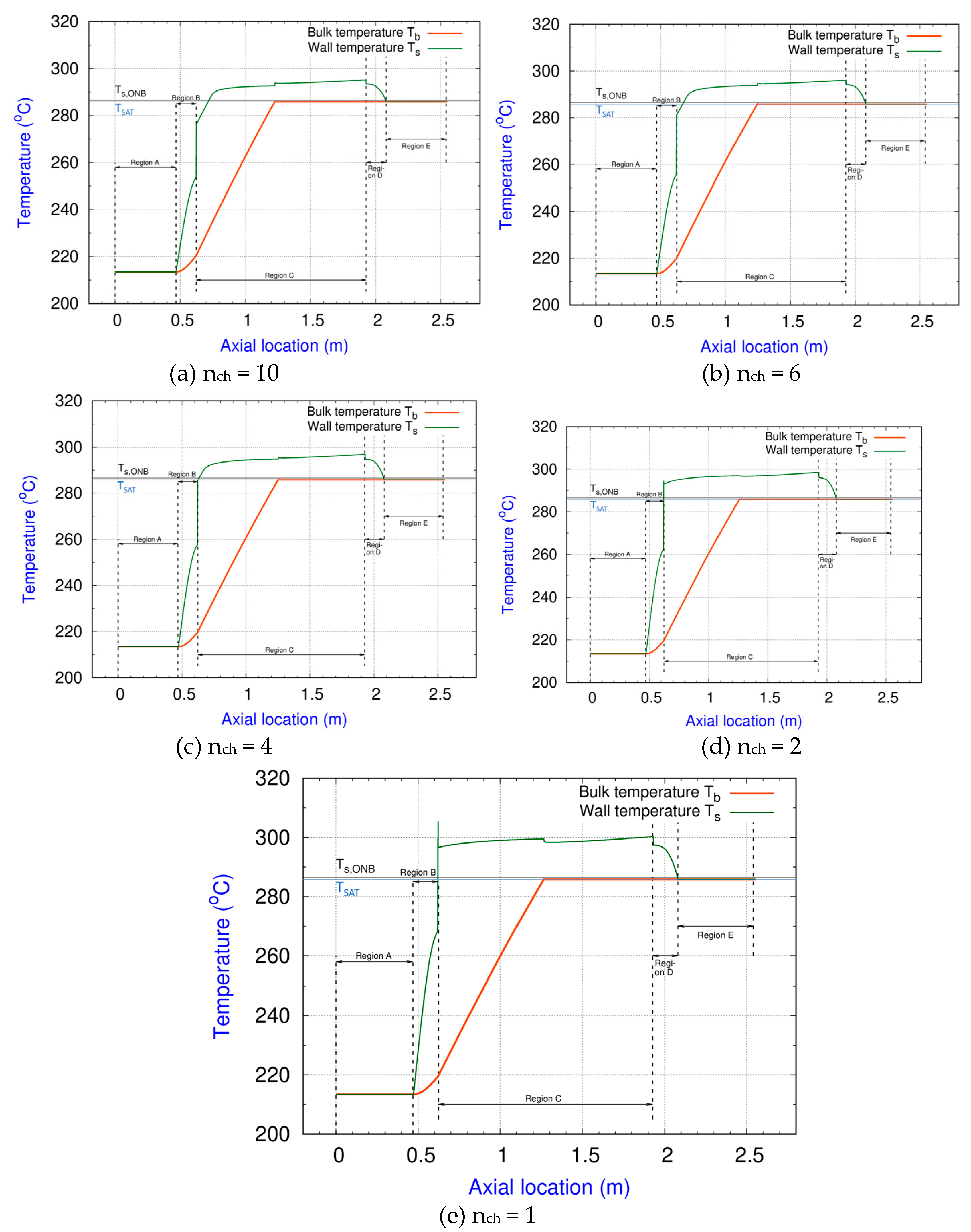
Figure 11.
Evolution of the heat transfer enhancement factor ψ for different number of channels in the FW.
Figure 11.
Evolution of the heat transfer enhancement factor ψ for different number of channels in the FW.
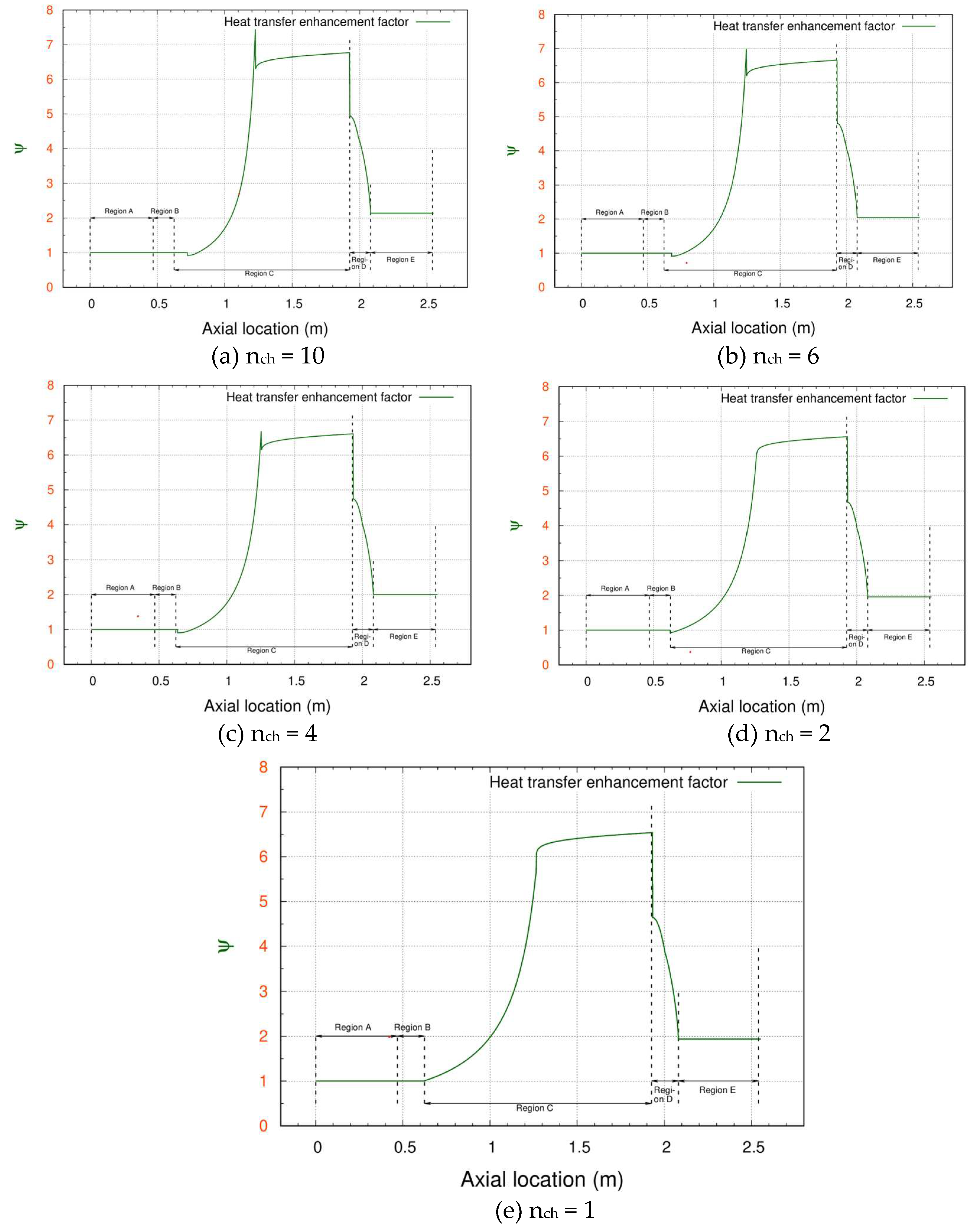
Figure 13.
Comparison of the maximum heat flux given to a FW channel and the CHF for the cases reported in Table 6.
Figure 13.
Comparison of the maximum heat flux given to a FW channel and the CHF for the cases reported in Table 6.
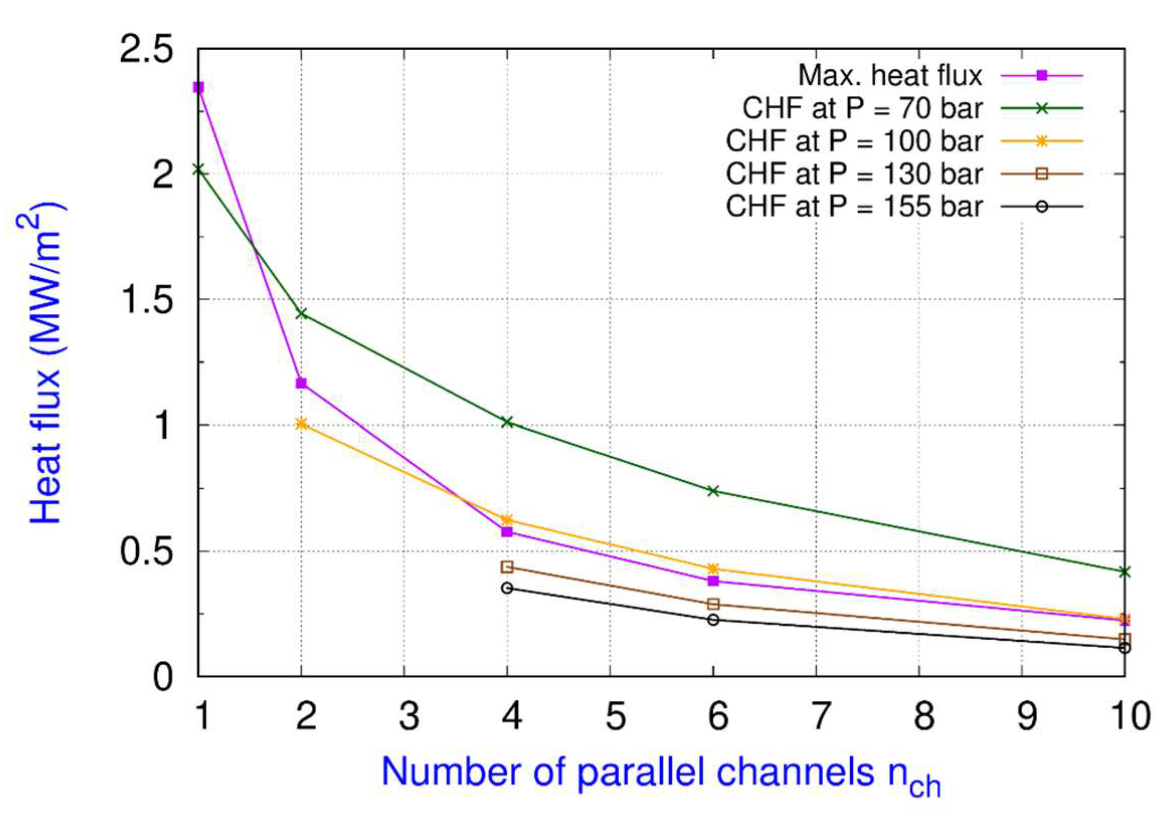
Figure 14.
Comparison of the maximum heat flux given to a FW channel and the CHF for the cases reported in Table 7.
Figure 14.
Comparison of the maximum heat flux given to a FW channel and the CHF for the cases reported in Table 7.
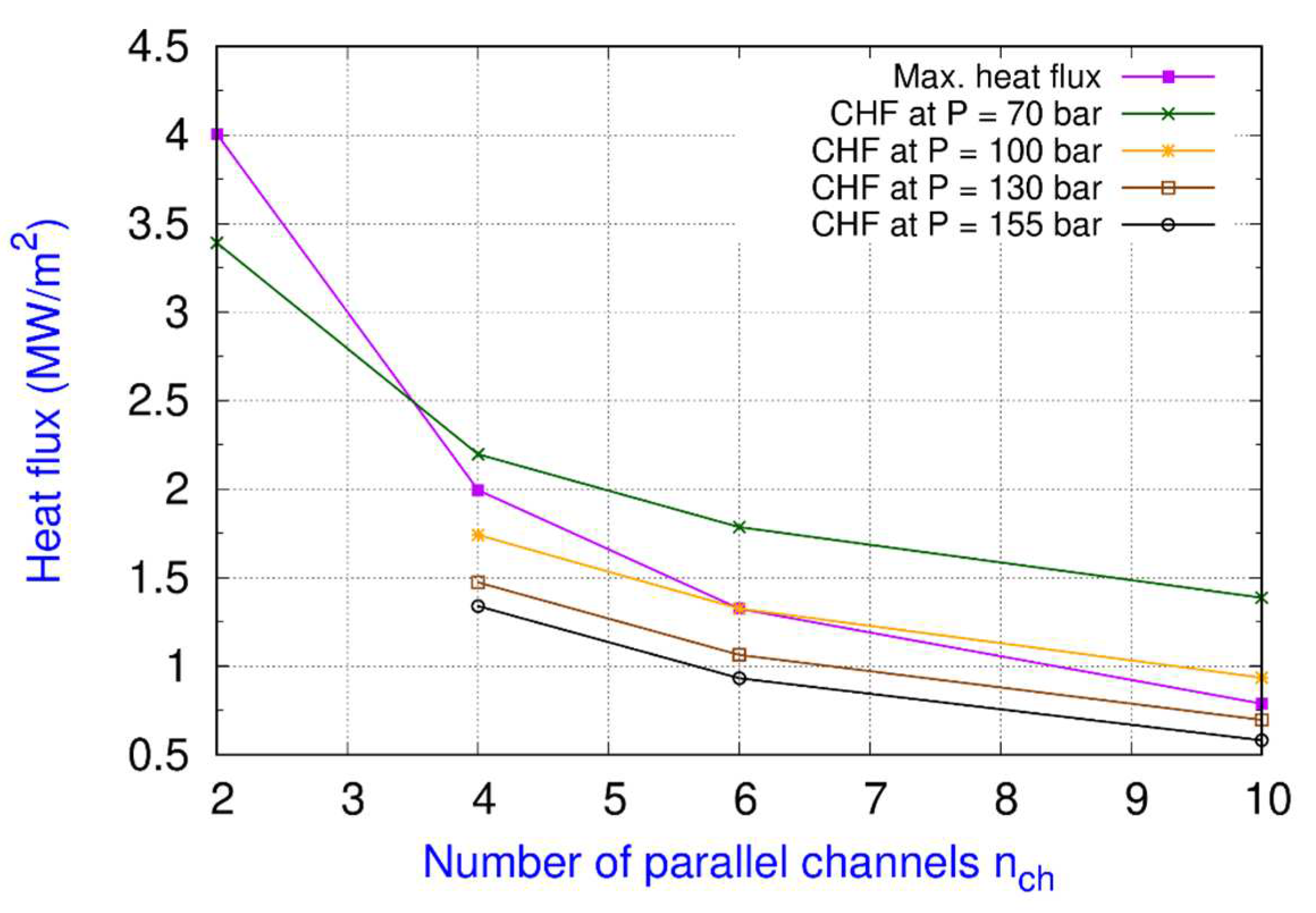

Table 1.
Geometrical specifications of different BB cells.
| Property | COB | IB | IB apical |
| Length (mm) | 1500 | 1127 | 1290.4 |
| FW Width (Total width) (mm) | 567(1000) | 364(800) | 554.91 |
| Height (mm) | 135 | 135 | 146 |
| Left elbow angle | 90 | 95 | 90 |
| Right elbow angle | 90 | 95 | 95 |
Table 2.
Thermal loads on different BB cells.
| BB cell | HF module | Q3 module |
HFmax [MW/m2] | Q3max [MW/m3] | |||
| Charged particles |
Thermal radiation |
Total | Tungsten | Eurofer | |||
| COB | m23 | O4 | 0.06 | 0.26 | 0.32 | 26.8 | 8.4 |
| IB | m2 | I3 | 0.08 | 0.19 | 0.27 | 23.4 | 7.5 |
| IB apical | m8 | I7 | 1.09 | 0.18 | 1.27 | 17.3 | 6.03 |
Table 3.
Proposed and analyzed operating conditions.
| Operating condition number | 1 | 2 | 3 | 4 |
| System pressure (bar) | 70 | 100 | 130 | 155 |
Table 4.
Cases and the respective inputs for the validation exercise.
| Case # | System | nch | Water Tinlet (oC) | Water mass flow rate (kg/s) | Total Power (kW) |
| 1 | COB | 10 | 295.0 | 0.53110 | 102.82 |
| 2 | COB | 6 | 295.0 | 0.54315 | 105.15 |
| 3 | COB | 4 | 295.0 | 0.54918 | 106.32 |
| 4 | IB | 10 | 295.0 | 0.32720 | 63.35 |
| 5 | IB | 4 | 295.0 | 0.35130 | 68.0 |
| 6 | IBapical | 10 | 295.0 | 1.45200 | 281.1 |
Table 5.
Results for various operating conditions of the water for the COB equatorial cell.
| Pressure (bar) | nch | Water mass flow rate (kg/s) | xout | Ts,ONB (oC) | zS,ONB (m) | zs,SAT (m) | khor | Qtot (kW/m2) |
| 70 | 10 | 0.136 | 0.269 | 286.52 | 0.724 | 1.228 | 0.698 | 102.82 |
| 6 | 0.142 | 0.256 | 286.73 | 0.684 | 1.246 | 0.753 | 105.15 | |
| 4 | 0.147 | 0.25 | 286.94 | 0.64 | 1.256 | 0.8 | 106.3 | |
| 2 | 0.149 | 0.245 | 287.42 | 0.624 | 1.262 | 0.888 | 107.4 | |
| 1 | 0.151 | 0.243 | 288.08 | 0.624 | 1.267 | 0.985 | 107.94 | |
| 100 | 10 | 0.111 | 0.328 | 311.58 | 0.82 | 1.323 | 0.681 | 102.82 |
| 6 | 0.116 | 0.314 | 311.75 | 0.778 | 1.34 | 0.735 | 105.15 | |
| 4 | 0.119 | 0.308 | 311.93 | 0.738 | 1.348 | 0.782 | 106.32 | |
| 130 | 10 | 0.100 | 0.365 | 331.37 | 0.896 | 1.417 | 0.67 | 102.82 |
| 6 | 0.104 | 0.35 | 331.53 | 0.856 | 1.432 | 0.723 | 105.15 | |
| 4 | 0.106 | 0.345 | 331.68 | 0.812 | 1.437 | 0.769 | 106.32 | |
| 155 | 10 | 0.095 | 0.385 | 345.27 | 0.957 | 1.499 | 0.663 | 102.82 |
| 6 | 0.098 | 0.372 | 345.42 | 0.911 | 1.512 | 0.716 | 105.15 | |
| 4 | 0.1 | 0.366 | 345.57 | 0.869 | 1.518 | 0.761 | 106.32 |
Table 6.
Results for various operating conditions of the water for the IB cell.
| Pressure (bar) | nch | Water mass flow rate (kg/s) | xout | Ts,ONB (oC) | zS,ONB (m) | zs,SAT (m) | khor | Qtot (kW/m2) | |
| 70 | 10 | 0.108 | 0.157 | 286.47 | 0.49 | 0.972 | 0.621 | 63.35 | |
| 6 | 0.118 | 0.143 | 286.67 | 0.472 | 1.016 | 0.67 | 66.781 | ||
| 4 | 0.121 | 0.140 | 286.87 | 0.434 | 1.026 | 0.713 | 67.999 | ||
| 2 | 0.122 | 0.138 | 287.30 | 0.42 | 1.024 | 0.79 | 68.161 | ||
| 1 | 0.122 | 0.137 | 287.92 | 0.42 | 1.025 | 0.877 | 68.505 | ||
| 100 | 10 | 0.084 | 0.200 | 311.54 | 0.549 | 1.025 | 0.606 | 63.349 | |
| 6 | 0.091 | 0.184 | 311.70 | 0.53 | 1.066 | 0.654 | 66.781 | ||
| 4 | 0.093 | 0.18 | 311.86 | 0.493 | 1.077 | 0.696 | 67.999 | ||
| 2 | 0.094 | 0.179 | 312.23 | 0.42 | 1.072 | 0.772 | 68.161 | ||
| 130 | 10 | 0.072 | 0.232 | 331.33 | 0.592 | 1.075 | 0.596 | 63.349 | |
| 6 | 0.078 | 0.216 | 331.48 | 0.572 | 1.115 | 0.644 | 66.781 | ||
| 4 | 0.08 | 0.211 | 331.62 | 0.535 | 1.125 | 0.684 | 67.999 | ||
| 155 | 10 | 0.066 | 0.253 | 345.24 | 0.619 | 1.12 | 0.59 | 63.349 | |
| 6 | 0.071 | 0.236 | 345.38 | 0.599 | 1.158 | 0.637 | 66.781 | ||
| 4 | 0.073 | 0.231 | 345.51 | 0.562 | 1.168 | 0.677 | 67.999 | ||
Table 7.
Results for various operating conditions of the water for the IB apical cell.
| Pressure (bar) | nch | Water mass flow rate (kg/s) | xout | Ts,ONB (oC) | zS,ONB (m) | zs,SAT (m) | khor | Qtot (kW/m2) |
| 70 | 10 | 0.555 | 0.102 | 287.041 | 0.771 | 1.432 | 0.745 | 281.096 |
| 6 | 0.561 | 0.101 | 287.4 | 0.702 | 1.434 | 0.805 | 283.338 | |
| 4 | 0.564 | 0.101 | 287.757 | 0.640 | 1.436 | 0.855 | 284.459 | |
| 2 | 0.567 | 0.1 | 288.561 | 0.587 | 1.438 | 0.948 | 285.58 | |
| 100 | 10 | 0.419 | 0.135 | 312.01 | 0.827 | 1.479 | 0.728 | 281.096 |
| 6 | 0.424 | 0.134 | 312.31 | 0.759 | 1.481 | 0.786 | 283.338 | |
| 4 | 0.426 | 0.133 | 312.609 | 0.698 | 1.483 | 0.835 | 284.459 | |
| 130 | 10 | 0.353 | 0.161 | 331.754 | 0.864 | 1.527 | 0.716 | 281.096 |
| 6 | 0.357 | 0.159 | 332.020 | 0.797 | 1.529 | 0.773 | 283.338 | |
| 4 | 0.359 | 0.158 | 332.286 | 0.737 | 1.531 | 0.821 | 284.459 | |
| 155 | 10 | 0.318 | 0.178 | 345.636 | 0.888 | 1.571 | 0.708 | 281.096 |
| 6 | 0.321 | 0.177 | 345.887 | 0.821 | 1.571 | 0.765 | 283.338 | |
| 4 | 0.323 | 0.175 | 346.136 | 0.763 | 1.573 | 0.813 | 284.459 |
Disclaimer/Publisher’s Note: The statements, opinions and data contained in all publications are solely those of the individual author(s) and contributor(s) and not of MDPI and/or the editor(s). MDPI and/or the editor(s) disclaim responsibility for any injury to people or property resulting from any ideas, methods, instructions or products referred to in the content. |
© 2023 by the authors. Licensee MDPI, Basel, Switzerland. This article is an open access article distributed under the terms and conditions of the Creative Commons Attribution (CC BY) license (http://creativecommons.org/licenses/by/4.0/).
Copyright: This open access article is published under a Creative Commons CC BY 4.0 license, which permit the free download, distribution, and reuse, provided that the author and preprint are cited in any reuse.


