
Submitted:
12 December 2023
Posted:
12 December 2023
You are already at the latest version
Abstract
To meet the International Maritime Organization’s requirements for carbon dioxide emissions from ships, a cost-effective and practical ship decarbonization tower was autonomously designed based on the marine diesel engine model 6135G128ZCa. The tower is internally filled with structured packing, and a slot-type liquid distributor at the top of the packing evenly distributes the NaOH solution to absorb carbon dioxide from the ship’s exhaust gas. Experimental research was conducted to investigate the influence of factors such as liquid-to-gas ratio and NaOH concentration on the performance of the decarbonization tower. The results confirmed that the use of NaOH solution can effectively absorb CO2 from ship exhaust gas, reducing CO2 emissions by more than 81.59% and meeting the EEDI (Energy Efficiency Design Index) requirements specified by the IMO.
Keywords:
ship CO2
; decarbonization tower
; liquid-to-gas ratio
; NaOH concentration
1. Introduction
Maritime In recent years, global warm-ing-induced ocean acidification, polar ice melting, sea level rise, droughts and hurricanes have had a serious impact on the global eco-system and sustainable economic development. Excessive emissions of carbon dioxide (CO2), which account for about 80% of total green-house gas emissions, are reported to be the main cause of global warming. The signing of the Paris Climate Agreement signaled a con-sensus among countries to reduce GHG emis-sions[1]. According to the International En-ergy Agency (IEA) "CO2 Emission Report 2022", the global CO2 emissions in 2022 will reach 36.8 billion tons, and China’s CO2 emissions will be 12.1 billion tons, accounting for 32.88% of the global total [2], in the con-text of China’s rapid economic growth, the industrial development of the country is facing enormous pressure to reduce CO2 emissions. In September 2020, China clearly put forward the goal of "carbon peak" in 2030 and "carbon neutral" in 2060.A research report by the International Maritime Organization (IMO) indicates that in 2020, CO2 emissions from global shipping accounted for approximately 6% of the world’s total CO2 emissions. Without proper control measures, global maritime CO2 emissions could double by the mid-21st century [3]. The 80th session of the IMO Marine Environment Protection Committee (MEPC 80) was held on July 7, 2023. During the meeting, the committee revised the strategy for reducing greenhouse gas emissions from ships. The new targets for emission reduction are as follows: to peak international shipping’s greenhouse gas emissions as soon as possible and achieve net-zero emissions around 2050, taking into account different national circumstances. By 2030, the annual total greenhouse gas emissions from international shipping should be reduced by at least 20% compared to 2008 levels, with a further ambition to reduce by 30%. By 2040, the annual total greenhouse gas emissions from international shipping should be reduced by at least 70% compared to 2008 levels, with a further ambition to reduce by 80% [4].
At present, carbon dioxide capture in the field of ships is still mainly concentrated in the field of land-based exhaust emission control, and the main technologies include physical adsorption, chemical absorption, membrane absorption, etc[5]. Physical adsorption method refers to under certain conditions, the exhaust gas through the bed filled with porous materials, flue gas in the CO2 through physical and chemical bonding adsorption on the sur-face of the adsorbent material, and N2 and other gases flow directly through the bed, to be adsorbed saturated through the lowering of the system pressure or heating, vacuum, desorption of high concentrations of CO2 gas prod-ucts.According to the difference of the de-sorption process, the adsorption method can be divided into variable pressure adsorption [6,7,8], variable temperature adsorption and combined variable temperature/variable pressure adsorp-tion. Adsorbents used in adsorption methods include solid amines [9], carbon materials [10], molecular sieves [11], metal-organic skeletons (MOF) [12] and others. Silica-based materials represented by mesoporous silica (MPS) and zeolite (Z0L) are rich in variety, synthesized by various methods, with porous and regular structures and large specific surface areas, and thus are widely used as solid amine adsorption carriers [13,14]; WU et al [15] synthesized porous carbon materials rich in mesoporous structures by hydrothermal/templating method by using chitosan as a carbon source and F127 as a soft templating agent and demonstrated good CO2 adsorption performance. demon-strated good CO2 adsorption effect. Zhang Xueshi et al [1[16,17,18,19] studied the molecular sieve-type CO2 absorption, using some amino substances adsorbed on the molecular sieve to absorb CO2, this by grafting amino groups in the mesoporous molecular sieve, opened up a new direction of molecular sieve method to remove CO2. Membrane separation method [20,21,22] is the use of gas molecules in the membrane material of the dissolution and diffusion coefficient of the difference between the two sides of the film pressure difference as the separation power, high permeability of the gas quickly through the film, low permeability of the gas is retained in the other side of the film, so as to realize the separation of gas[23]. Chemical absorption is the removal of carbon dioxide from exhaust gases through the chemical reaction between carbon dioxide and absorbent, and the chemical absorption process is a simultaneous process of mass transfer and reaction[24], and common chemical absor-bents include ammonia, organic amine solu-tions, and other alkaline solutions, etc. [25], and chemical absorption, as a relatively mature and the most marketable carbon capture tech-nology, has attracted the attention of many researchers. Park et al[26] could reduce the extra energy required for mineralization and fixation of CO2 to form metal carbonates by adding CaO to the saturated solution of CO2 absorbed by NaOH and KOH. Chiang et al [27] added glycerol to the aqueous sodium hy-droxide solution could significantly increase the total CO2 absorption efficiency; the study of Shen Heming et al[28] from Jiangnan University used calcium hydroxide to solidi-fication, explored the effects of CO2 concen-tration and carbonization time on the carbon-ization rate as well as the strength of carboni-zation products, and the results showed that uneven carbonization was the main factor leading to the lower strength of carbonization products at high CO2 concentration; Wang et al[29] proposed a method of absorbing CO2 from the exhaust gas of a ship by using an alkaline NaOH solution, and designed a system for decarbonization of a ship, and the study showed that the CaO The presence of solid particles can improve the decarbonization ef-ficiency of NaOH solution to absorb CO2 from ship exhaust.Johny et al[30] developed a sim-ple and practical CO2 capture device, which absorbs CO2 by spraying NaOH solution through a nozzle to produce Na2CO3.It was found that the absorption rate of CO2 was maximum at a molar concentration of 5 mol/L of NaOH solution.
In this paper, based on the marine 6135G128ZCa diesel engine, an economical and practical decarbonization tower for ships is designed independently, the tower is filled with regular packing inside, and the NaOH solution is uniformly distributed in the regular packing to absorb carbon dioxide in the diesel exhaust through the slot liquid distributor at the top of the packing layer, and the effects of liquid/gas ratio and NaOH concentration on the perfor-mance of the decarbonization tower are studied through the experiments.
2. Experimental Principles and Methods
2.1. Principle of CO2 Absorption by NaOH Solution
The absorption of CO2 by NaOH solution is mainly achieved using inexpensive industrial chemical NaOH through an acid-base neutralization reaction to absorb CO2. The reaction equation is as follows:
Since Na2CO3 is a basic substance, when there is insufficient NaOH in the reaction, the Na2CO3 present in the solution still has the ability to absorb CO2. The absorption process is as follows:
In this text, since there is an excess of NaOH in the solution, the efficiency of CO2 absorption is calculated based on Equation (1).
2.2. CO2 Absorption Efficiency and Liquid-to-Gas Ratio
CO2 absorption efficiency is an indicator that measures the effectiveness of NaOH solution in absorbing carbon dioxide. It is typically expressed as a percentage, representing the ratio of the amount of CO2 absorbed after passing through the decarbonization tower to the amount of CO2 before absorption. It is an average value. The calculation formula is shown as Equation (3):
In the equation, represents the absorption efficiency of CO2, q is the volumetric flow rate of CO2 in the exhaust gas, measured in m³/h. The subscript "B" denotes the parameters before CO2 absorption, and the subscript "L" denotes the parameters after CO2 absorption.
The liquid-to-gas ratio refers to the volume ratio between the liquid phase and the gas phase in the absorption process. It is an indicator that measures the relative content of liquid and gas during the absorption process. The calculation formula is shown as Equation (4):
In the equation, represents the liquid-to-gas ratio, is the volumetric flow rate of the liquid phase, and is the volumetric flow rate of the exhaust gas, measured in Nm³/h.
2.3. Ship CO2 Absorption Cycle System
Based on the NaOH solution’s ability to absorb CO2 from ships, a ship CO2 absorption system is designed in conjunction with the parameter characteristics of the marine 6135G128ZCa diesel engine at the Shanghai Maritime University Diesel Engine Testing Center, as shown in Figure 1.
When the ship diesel engine operates at 90% load, the exhaust gases are directed to the exhaust pipe and decarbonization tower. The exhaust gases that enter the exhaust pipe are directly discharged into the atmosphere, while the gases entering the decarbonization tower pass through a cooler to lower the temperature to around 50°C. Then, they enter the bottom of the decarbonization tower through the gas inlet. The alkaline solution is supplied to the tray-type liquid distributor in the decarbonization tower through the liquid circulation system. The alkaline solution is evenly sprayed onto the packing balls through openings or slits. The gas rises from the bottom of the tower and comes into contact with the alkaline solution sprayed evenly by the tray-type liquid distributor. A chemical reaction occurs between the gas and the alkaline solution, and carbon dioxide is absorbed by the alkaline solution. The purified gas is finally discharged from the top of the tower, while the reacted alkaline solution flows into the mixing tank through the bottom outlet of the tower.
Figure 1.
Recovery system of ship’s CO2.
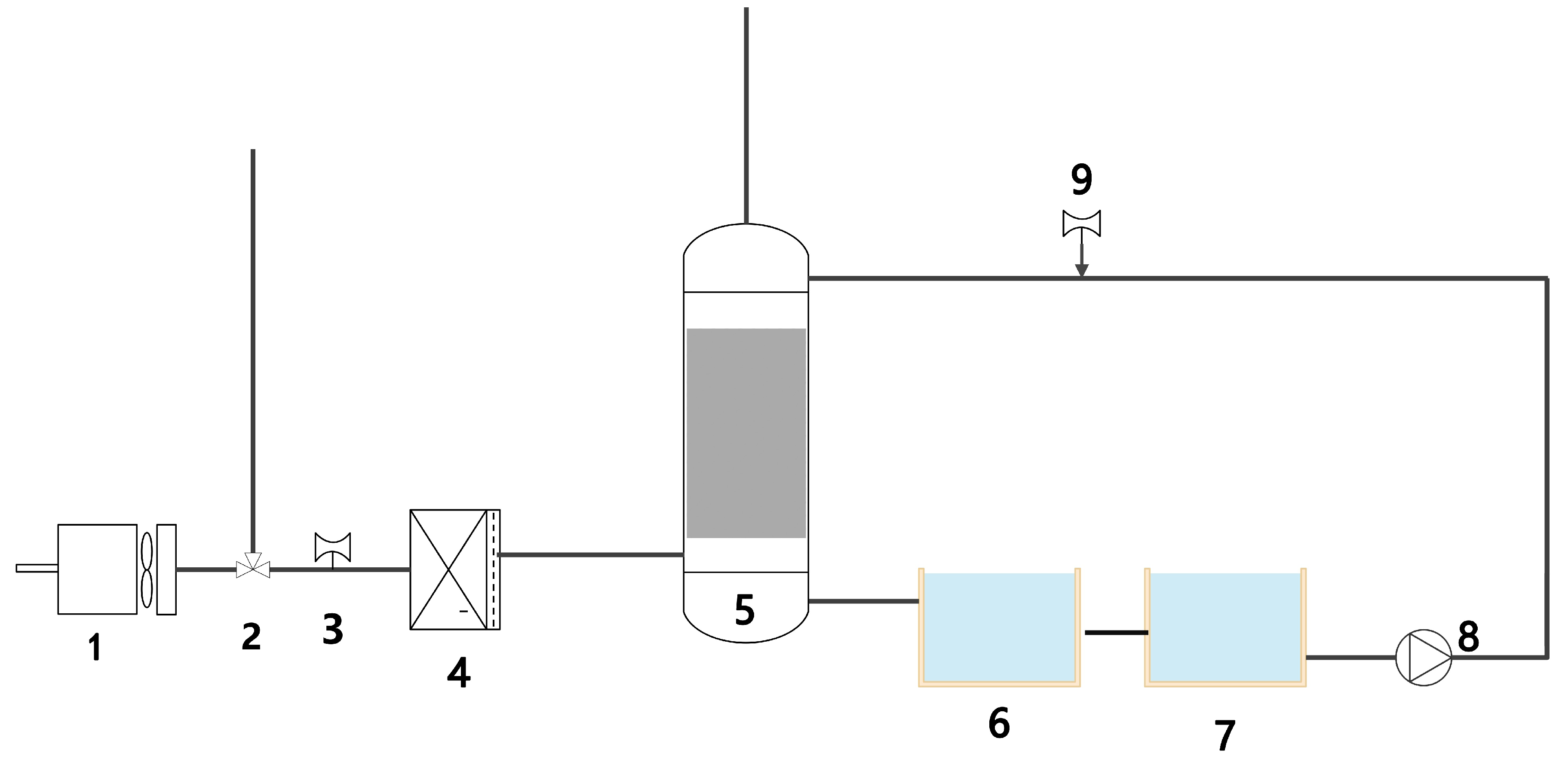
1.6135G128Ca diesel engine 2. Three-way valve 3. Smoke flow meter 4. Cooler 5. Hybrid decarbonization tower 6. Mixing tank 7. Chemical storage cabinet 8. Chemical pump 9. Chemical flow meter
3. Experimental Equipment
3.1. Marine Diesel Engine
The selected diesel engine for the experiment is the marine 6135G128ZCa diesel engine, which is currently available at the Shanghai Maritime University Diesel Engine Testing Center, as shown in Figure 2. The power output of the engine is equipped with a hydraulic dynamometer manufactured by Nantong Testing Equipment Factory. The model is W440, with a maximum power of 440 kW, a maximum speed of 5000 r/min, and a maximum torque of 1800 N·m. The diesel engine exhaust is equipped with a smoke gas cooler, which can cool the smoke gas temperature within the range of 25 °C to 400 °C. The engine parameters are listed in Table 1.
Figure 2.
6135G128ZCa Diesel Engineer.
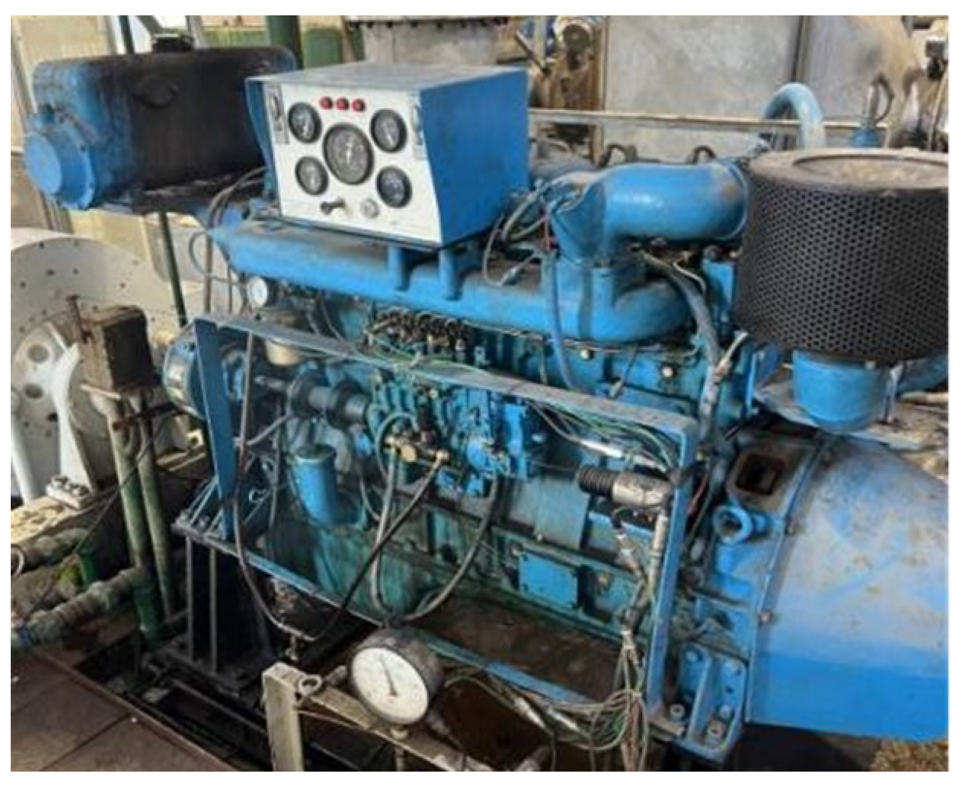

Table 1.
6135G128ZCa Diesel Engineer.
| Name | Value | Name | Value |
|---|---|---|---|
| Bore | 135mm | Lubricating Oil Temperature | 95℃ |
| Stroke | 140mm | Cooling Water Temperature | 60/95℃ |
| Compression Ratio | 16 | Exhaust Pipe Flange | 80/83mm |
| Piston Displacement | 12.9L | Exhaust temperature | <580℃ |
| Continuous Power/Speed | 146kw/ 1500r·min-1 | Temperature at 25% Rated Speed | 327℃ |
| 12-hour Power Fuel Consumption Rate | 225.8 g·(kw·h)-1 | Temperature at 50% Rated Speed | 390℃ |
| 12-hour Power Oil Consumption Rate | 1.65 g·(kw·h)-1 | Temperature at 75% Rated Speed | 450℃ |
| Average Piston Speed at Rated Speed | 7.5m·s-1 | Temperature at 100% Rated Speed | 535℃ |
| Firing Order | 1-5-3-6-2-4 | Starting Method | Electric Start |
| Cooling Method r | Water-cooled |
3.2. Testing Equipment
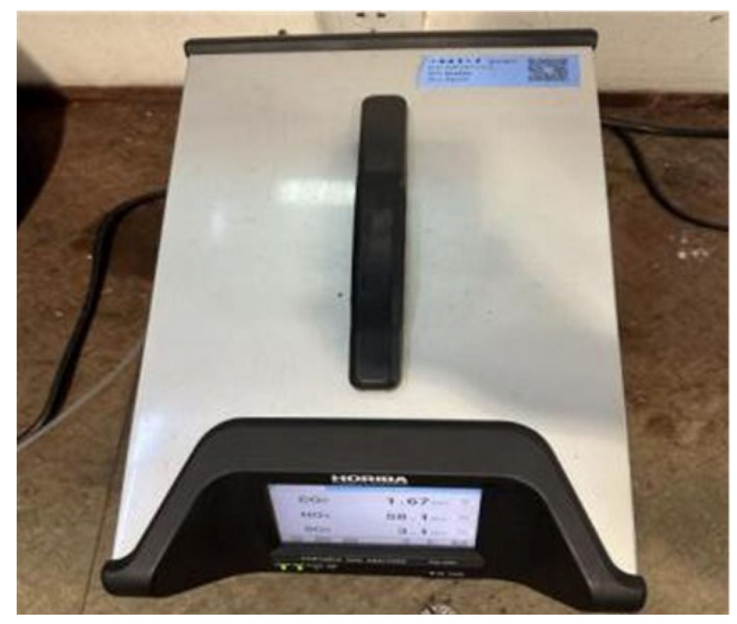
The exhaust gas composition testing equipment used for the diesel engine is the PG-300 portable gas analyzer, which consists of three components: the sampling component, power component, and analysis component, as shown in Figure 2. The PG-300 smoke gas analyzer utilizes advanced sensors and measurement technology, providing high precision and fast response. It can deliver accurate measurement results and real-time monitoring of changes in exhaust gas composition. The PG-300 smoke gas analyzer can measure several key parameters, such as oxygen content (0-25 Vol%), carbon monoxide (0-5000 ppm), carbon dioxide (0-30 Vol%), nitrogen oxides (0-2500 ppm), and so on.
Figure 3.
PG-300 smoke gas analyzer.
4. Design of Decarbonization Tower
A simple and practical decarburization tower is designed independently based on the marine 6135G28Ca diesel engine of Shanghai Maritime University Diesel Engine Test Center. The specific design is shown in Figure 4. The decarburization tower is mainly composed of cylinder, header, regular packing, trough liquid distributor, gas-liquid inlet and outlet. The decarbonization tower has a vertical tower structure, made of corrosion-resistant material stainless steel, tower height 3.3m, cylinder diameter 0.4m, the tower is installed inside the cylinder packing support plate, used to support the packing and separation of gas-liquid flow. The central part of the cylinder is filled with regular packing, which can increase the gas-liquid contact area, and there is a trough-type liquid distributor installed at the top of the tower, which is designed to distribute the lye evenly on the packing layer to ensure that the lye can cover the whole surface of the packing and provide the best gas-liquid contact. The decarbonization tower is externally equipped with a liquid circulation system: this consists of pumps and circulation pipes. These systems are used to circulate and distribute the lye to the tank liquid distributor to ensure a continuous supply of absorbing liquid and to enable the CO2 absorption reaction.
The decarbonization tower works on the principle that the engine exhaust gas, which contains carbon dioxide and other gaseous components, is piped into the bottom of the decarbonization tower and enters through the gas inlet. The lye is supplied through a liquid circulation system to the decarbonization tower’s trough liquid distributor, which is located at the top of the tower and sprays the lye uniformly onto the packing layer. The tail gas rises from the bottom and comes into contact with the lye sprayed by the tank liquid distributor on the packing layer. Under the action of the packing, the carbon dioxide in the tail gas reacts chemically with the lye to form sodium bicarbonate. During this reaction, the carbon dioxide is effectively captured and absorbed. After the absorption reaction, the purified gas is discharged from the top of the tower and the lye containing sodium carbonate is discharged from the bottom of the decarbonization tower into the mixing cabinet.
Figure 4.
Design diagram of a decarbonization tower.
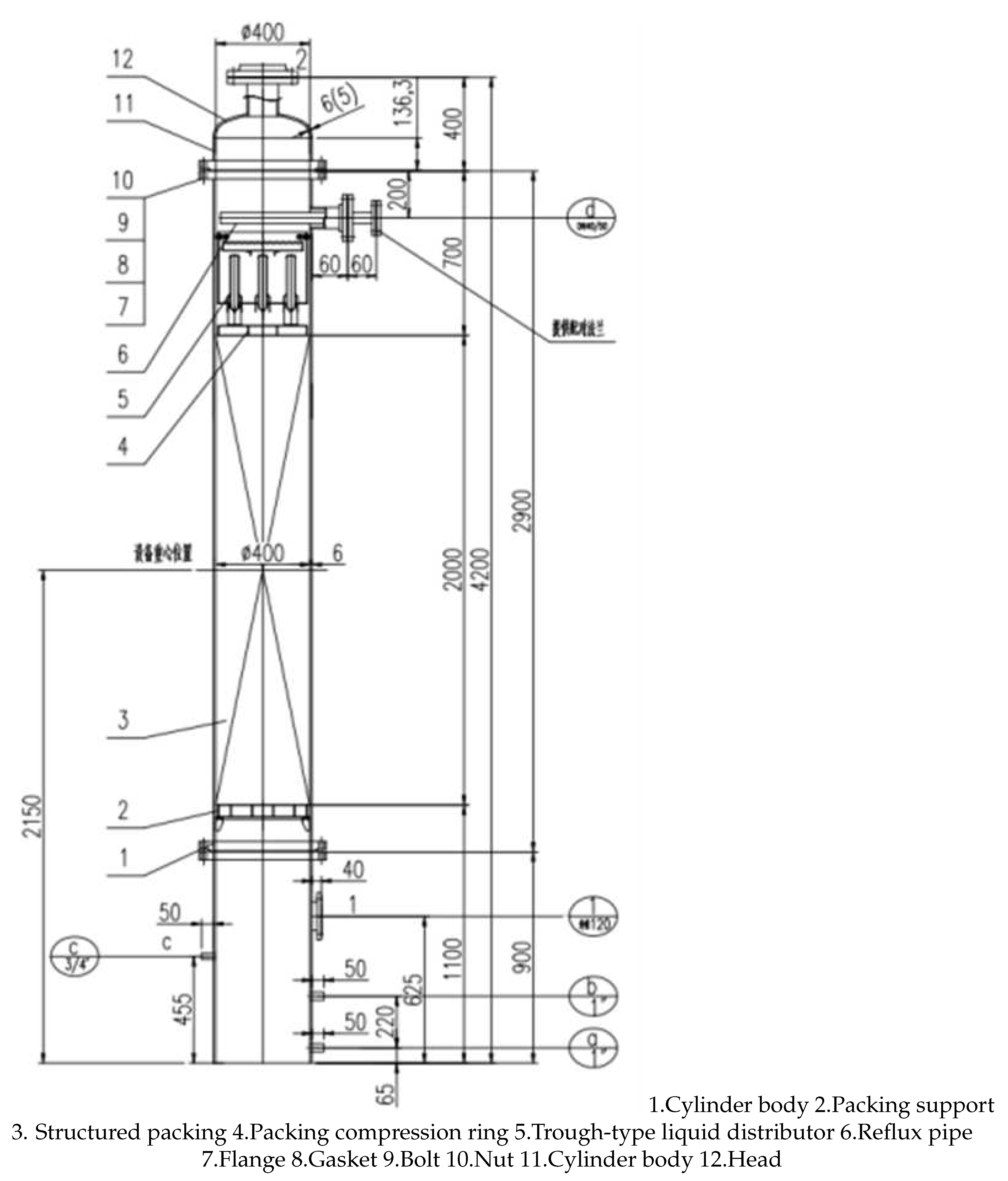
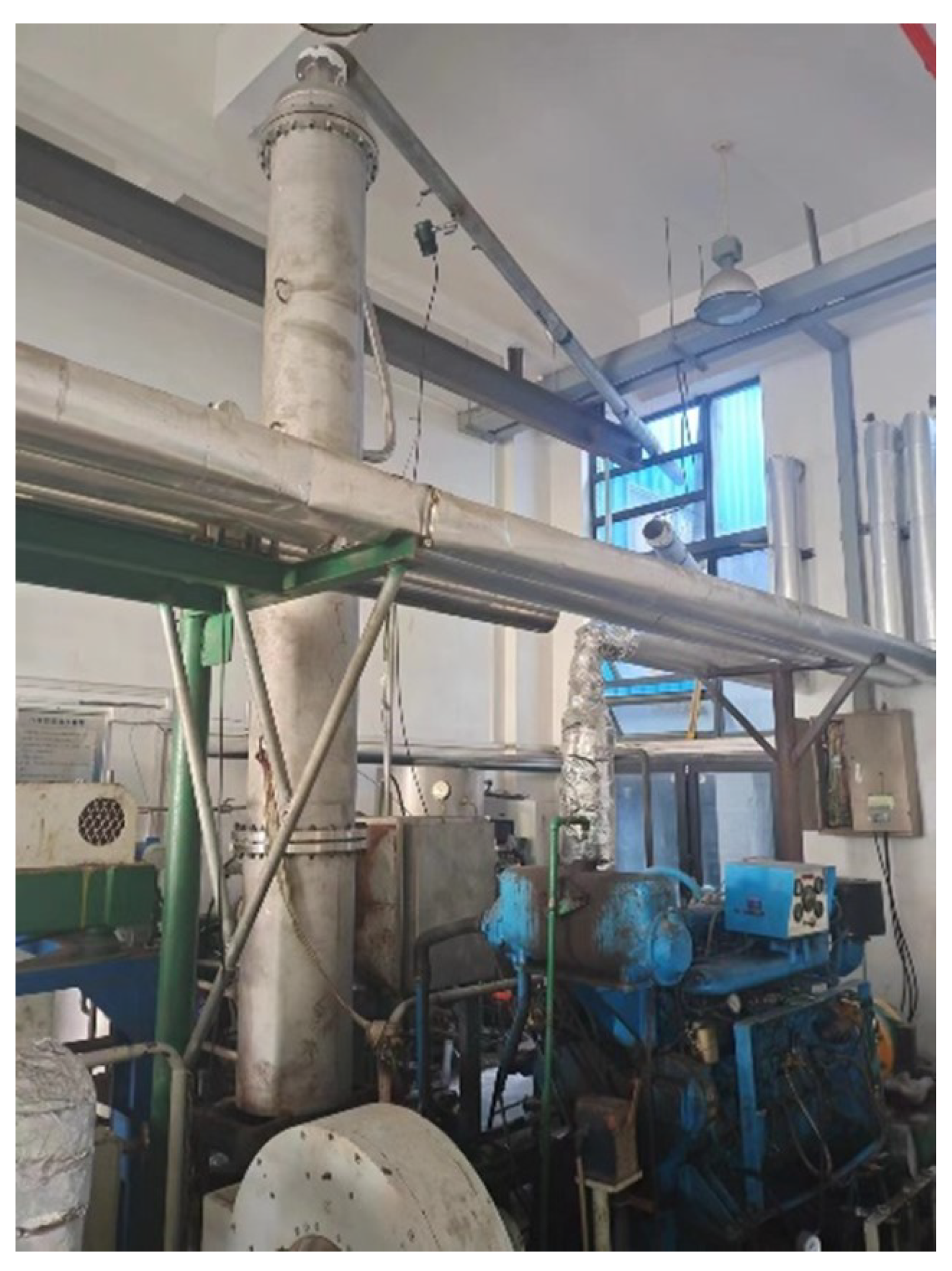
Figure 5.
Physical Diagram of Decarbonization Tower, Model 6135.
5. Experimental Results and Analysis
The test was selected 6135G128ZCa marine diesel engine based on 90% load operation, configured with 2 mol/L NaOH solution, the flow rate of exhaust gas into the decarburization tower was controlled by adjusting the three-way valve to be 500Nm3/h, 750Nm3/h and 1000Nm3/h, and the flow rate of lye was controlled by the drug pump to be 0.5Nm3/h, 1Nm3/h, 2Nm3/h. The CO2 uptake rate calculated according to Equation (3) is shown in Table 2.
Table 2.
Experimental data.
| Gas flow rate/Nm³·h-1 | Liquid flow rate/ m³·h-1 | Liquid-to-gas ratio | absorption rate/% |
|---|---|---|---|
| 500 | 0.5 | 1 | 55.84 |
| 500 | 1 | 2 | 73.99 |
| 500 | 2 | 4 | 81.59 |
| 750 | 0.5 | 0.67 | 35.63 |
| 750 | 1 | 1.33 | 45.27 |
| 750 | 2 | 2.67 | 61.51 |
| 1000 | 0.5 | 0.5 | 25.61 |
| 1000 | 1 | 1 | 35.07 |
| 1000 | 2 | 2 | 53.85 |
5.1. Influence of Liquid-to-Gas Ratio on Decarbonization Efficiency
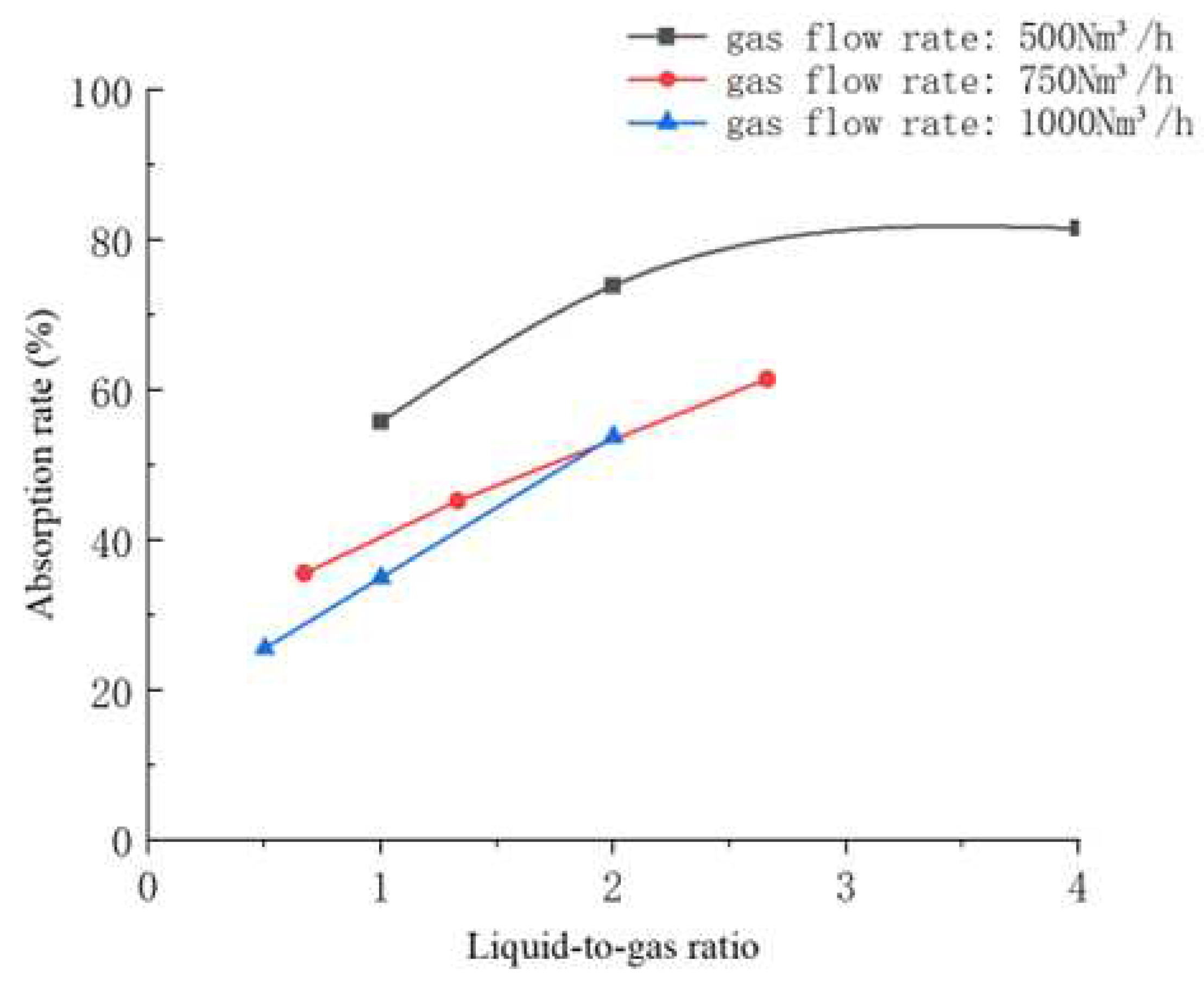
As can be seen from Figure 6, under the same conditions of tail gas flow, the decarburization rate shows an increasing trend with the increase of liquid-gas ratio, in which the decarburization rate is the highest in the case of tail gas flow rate of 500 Nm3/h and liquid-gas ratio of 4, which is up to 81.59%; however, with the increase of the liquid-gas ratio, the effect of the liquid-gas ratio on the decarburization rate gradually decreases, for example, in the case of the tail gas flow rate of 500 Nm3/h, the increase of the liquid-gas ratio from 1 For example, in the tail gas flow rate of 500 Nm3/h, the decarburization rate increased by 18.15% from 1 to 2, and the decarburization rate increased by only 7.6% from 2 to 4. This phenomenon may be due to the following reasons:
(1) Reaction rate limitation: In the decarbonization process, NaOH in the lye reacts with CO2 in the gas phase to produce sodium carbonate. And the liquid-gas ratio in the test is realized by adjusting the lye flow rate. When the liquid-gas ratio is low, the liquid is more sufficient compared with the gas phase, and the reaction rate is mainly limited by the mass transfer rate of the gas phase. Therefore, increasing the liquid-gas ratio can improve the contact degree between the liquid phase and the gas phase and promote the reaction between CO2 in the gas phase and NaOH in the liquid phase. However, with the increase of the liquid-gas ratio, the degree of excess of the liquid relative to the gas phase gradually decreased, and the reaction rate began to be limited by the mass transfer rate of the liquid phase, resulting in a weakening of the gain in decarburization rate.
(2) Increase in liquid film resistance: with the increase in the liquid to gas ratio, the lye in the mass transfer process to form the liquid film thickness increases. This will increase the resistance of liquid-phase mass transfer, slowing down the reaction rate of CO2 and lye in the liquid phase. Therefore, when the liquid-gas ratio is high, the effect of liquid film resistance on the reaction rate gradually appears, resulting in a weaker decarburization rate gain.
(3) Droplet collision and separation: In the liquid-gas contact process, the collision and separation between droplets and gas play an important role in the absorption and reaction of CO2. When the liquid-gas ratio is low, the collision and separation between droplets is relatively small, which is favorable to the absorption and reaction of CO2. However, with the increase of the liquid-gas ratio, the collision and separation between droplets increased, which might lead to some droplets failing to contact with the gas sufficiently, thus reducing the decarbonization efficiency.
In summary, with the increase of liquid-gas ratio, the absorption rate of CO2 in the tail gas by the alkaline solution gradually increased, but the limitations of the liquid-phase mass transfer rate and the collision and separation of liquid droplets gradually appeared, which led to a weakening of the gain effect of the decarbonization rate. Therefore, when determining the optimal liquid-gas ratio, factors such as reaction rate limitation and liquid-phase mass-transfer resistance need to be considered comprehensively to obtain the best decarbonization effect. In this test, the decarburization rate was highest under the condition of flue gas flow rate of 500Nm3/h, and when the liquid-gas ratio was greater than 2, the gain effect of liquid-gas ratio on decarburization rate was gradually weakened, so it can be concluded that the decarburization effect was best at the condition of flue gas flow rate of 500Nm3/h, and the liquid-gas ratio was 2, and it could reach 81.59%.
Figure 6.
Influence of Liquid-to-Gas Ratio on Decarbonization Efficiency.
5.2. Influence of NaOH Concentration on Decarbonization Efficiency
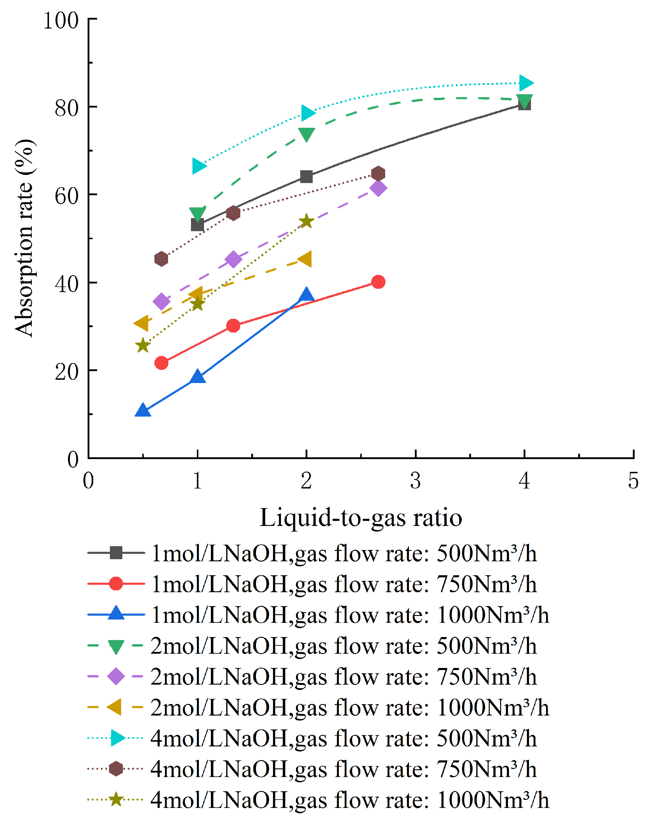
In order to study the effect of NaOH concentration on the decarbonization rate, the tests were carried out by configuring 1 mol/L and 4 mol/L NaOH solutions respectively under other unchanged test conditions, and the test results are shown in Figure 7.
As can be seen from Figure 7, in the case of tail gas flow rate of 500Nm3/h and 750Nm3/h, the higher the concentration of lye, the better the decarburization efficiency, in which in the case of tail gas flow rate of 500Nm3/h, 4mol/L lye concentration decarburization efficiency is the best, and with the increase of the liquid-gas ratio, the decarburization rate can reach a maximum of 85.37%; in the case of tail gas flow rate of 1000Nm3/h, low liquid-gas ratio decarburization rate of 1mol/L and 4mol/L NaOH solution is the best, and the decarburization rate can reach a maximum of 85.37%. In the case of the tail gas flow rate of 1000Nm3/h, the decarburization rate under the condition of low liquid/gas ratio increased with the increase of lye concentration, but when the liquid/gas ratio was more than 1.2, the decarburization rate corresponding to 2mol/L lye exceeded that of 4mol/L lye, and with the increase of the liquid/gas ratio, the effect of the gain of decarburization rate of 4mol/L lye was gradually weakened. Therefore, the following conclusions can be drawn:
(1) Within a certain range of NaOH concentration, the higher the concentration of NaOH, the better the decarbonization effect; NaOH is an alkaline substance, which dissociates into hydroxide ions (OH-) and sodium ions (Na+) in aqueous solution. These hydroxide ions are alkaline and can provide more alkaline active sites. During decarbonization, carbon dioxide reacts with hydroxide ions to form carbonate ions, which results in decarbonization. Therefore, increasing the NaOH concentration will provide more alkaline sites and increase the chance of carbon dioxide absorption and reaction, thus improving the decarbonization rate.
(2) The gain effect on the decarbonization rate is gradually weakened by too high a NaOH concentration; within a certain concentration range, increasing the NaOH concentration can improve the mass transfer rate of carbon dioxide and promote the decarbonization reaction. However, when the NaOH concentration is too high, the mass transfer process may no longer be the rate-limiting factor for the decarbonation reaction, and the high viscosity coefficient of the high-concentration NaOH solution is unfavorable to the gas-liquid mixing reaction, so the decarbonation rate could not be further improved even if the NaOH concentration was increased.
Under the comprehensive consideration of the supply of alkaline active sites, mass transfer rate and decarbonization rate, 1 mol/L NaOH solution corresponded to a low decarbonization rate, and 4 mol/L NaOH solution was too high in drug cost; only 2 mol/L NaOH solution could take into account of the multiple alkaline active sites and the high mass transfer efficiency to achieve the high decarbonization rate, and therefore, the optimal concentration of NaOH is 2 mol/L.
Figure 7.
Effect of NaOH Concentration on Decarbonization Efficiency.
6. Conclusions
In the paper, alkaline NaOH solution is utilized to absorb CO2 in ship’s exhaust gas, and a simple and practical 6135G128ZCa marine packing decarbonization tower is designed based on the marine 6135G128ZCa engine for testing, and its decarbonization efficiency can reach up to 81.59%, and the following conclusions can be obtained through this study:
(1)The method of utilizing NaOH solution to absorb CO2 in ship exhaust gas is feasible, which can effectively reduce the emission of CO2 from ships and satisfy the EEDI index specified in IMO.
(2)With the increase of liquid-gas ratio, the absorption rate of CO2 in the flue gas by alkaline solution is gradually increased, but the liquid-gas ratio and the absorption rate of CO2 are not proportional to each other, and the limitations of the liquid-phase mass transfer rate and droplet collision and separation gradually appear, resulting in a weakening of the gain effect of decarbonization rate.
(3) Within a certain range of NaOH concentration, the higher the NaOH concentration, the better the decarbonization effect; too high a concentration of NaOH on the decarbonization rate of the gain effect gradually weakened.
(4)The decarburization test was carried out by using a marine 6135G128ZCa packed decarburization tower, and the decarburization effect was best under the conditions of 2 mol/L NaOH concentration, 500 Nm3/h flue gas flow rate, and a liquid-to-gas ratio of 2.
Author Contributions
Writing-Origin Draft, Z.Z.; Writing-Review and Editing, Z.W. and H.G.; Supervision Z.W.; Data Curation, Z.Z., Z.H., D.C. All authors have read and agreed to the published version of the manuscript.
Funding
This research was funded by the National Key R&D program of China (No.2020YFB4300701).
Institutional Review Board Statement
Not applicable.
Informed Consent Statement
Not applicable.
Data Availability Statement
No new data were created or analyzed in this study. Data sharing is not applicable to this article.
Acknowledgments
We thank each of the authors for their contributions to this study. At the same time we would like to thank each editor and reviewer for their constructive comments and revisions to the manuscript.
Conflicts of Interest
The authors declare that they have no conflict of interest.
References
- STRECK C,KEENLYSIDE P, VONUNGER M. The paris agreement: A new beginning [J]. J Eur Environ Plan L, 2016,13(1): 3-29. [CrossRef]
- International Energy Agency. CO2 emissions in 2022[R]. Paris: IEA, 2023.
- HASAN M F, FIRST E L, BOUKOUVALA F, et al. A multiscale framework for CO2 capture, utilization, and sequestration: CCUS and CCU [J]. Comput Chem Eng, 2015, 81: 2-21. [CrossRef]
- Marine Environment Protection Committee (MEPC),80th session,2023. Initial IMO Strategy on Reduction of GHG Emissions from Ships[S].
- Jingliang Zhang, Sulin Zhao, Rongxiang Zhao et al. Research on modern carbon dioxide absorption process[J]. Contemporary Chemical Industry,2011,40(01):88-91.
- Chung,S.J.et al. "Dual-Phase Metal Carbonate Membrane for High-Temperature Carbon Dioxide Separation." Industrial & Engineering Chemistry Research 44 (2005): 7999-8006. [CrossRef]
- Dinda S .Development of solid adsorbent for carbon dioxide capture from flue gas[J].Separation and Purification Technology,2013,10964-71. [CrossRef]
- TONG Siqi, JIAN Weiwei, HAI Qiuyan, XIE Weixin, SUN Yi. Progress of CO2 adsorption on porous solid materials[J]. Journal of Liaoning University of Petrochemical Technology, 2022, 42(2): 30-37.
- Lei Ting, Yu Shunan, Zhou Changan et al. Research progress on molding technology of solid amine adsorbent for carbon capture by adsorption[J].Chemical Prgress 2022,41(12):62136225.DOI:10.16085/j.issn.1000-6613.2021-2238. [CrossRef]
- YU Hang,MENG Hong,YANG Xiangfu et al. Research progress of carbon-based carbon dioxide adsorbent materials[J]. Clean Coal Technology,2023,29(11):35-48.DOI:10.13226/j.issn.1006-6772.22081602. [CrossRef]
- Bae T ,Hudson R M ,Mason A J , et al.Evaluation of cation-exchanged zeolite adsorbents for post-combustion carbon dioxide capture[J].Energy environmental science: EES,2013,6(1):128-138.
- KONG Lingcong,SUN Yarong,XIE Yu et al. Progress and application of carbon dioxide capture technology by metal-organic framework materials[J]. Xinjiang Oil and Gas,2022,18(02):78-83. [CrossRef]
- Song T ,Zhao H ,Hu Y , et al.Facile assembly of mesoporous silica nanoparticles with hierarchical pore structure for CO2 capture[J].Chinese Chemical Letters,2019,30(12):2347-2350. [CrossRef]
- Vijaya T ,Viswateja K ,Spandana G , et al.Technoeconomic Investigation of Amine-Grafted Zeolites and Their Kinetics for COsub2/sub Capture.[J].ACS omega,2021,6(9):6153-6162. [CrossRef]
- WU Qiang, GAO Ming, ZHANG Gang et al. Preparation of biomass-based carbon materials with different morphologies and their application properties by hydrothermal/soft template method J]. Nanotechnology, 2019,30(18): 185702. [CrossRef]
- Zhang, Xueshi, Liu, Xinmin. Preparation and Performance of Modified Molecular Sieve for Carbon Dioxide Capture [J]. Techniques and Equipment for Environmental Pollution Control, 2015(10): 4995-4999. (in Chinese). [CrossRef]
- Zhang, Xueshi. Preparation of Amine Functional Porous Materials and Adsorption Properties for CO2 [D].Qingdao: Qingdao University of Science & Technology, 2015: 51-55. (in Chinese).
- Irani M, Gasem KA, Dutcher B, et al. CO2 captureusing nanoporous TiO(OH)2 /tetraethylenepentamine[J].Fuel,2016(183):601-608. [CrossRef]
- Cecilia J,Vilarrasa-García E,García-Sancho C, et al. Functionalization of hollow silica microspheres by impregnation or grafted of amine groups for the CO2 capture[J]. International Journal of Greenhouse Gas Control,2016,52. [CrossRef]
- Xu N ,Li X ,Franks A M , et al.Silver-molten carbonate composite as a new high-flux membrane for electrochemical separation of CO2 from flue gas[J].Journal of Membrane Science,2012,401-402190-194. [CrossRef]
- Ghezel-Ayagh H ,Jolly S ,Patel D , et al.Electrochemical Membrane Technology for Carbon Dioxide Capture from Flue Gas[J].Energy Procedia,2017,1082-9. [CrossRef]
- Electrochemical Membrane Technology for Carbon Dioxide Capturefrom Flue Gas[J].ECS Meeting Abstracts,2016. [CrossRef]
- Zhang N ,Pan Z ,Zhang Z , et al.CO2 capture from coalbed methane using membranes: a review[J].Environmental Chemistry Letters,2020,18(8):79-96. [CrossRef]
- Li X.C. Research on flue gas decarbonization technology of coal-fired power plant [J]. Clean Coal Technology,2009,15(03):6266. [CrossRef]
- Wang Hongbo. Research on carbon dioxide absorption by organic amine method[D]. Shanghai Normal University,2012.
- Park S W,Song K,Jo H. Laboratory-Scale Experiment on a Novel Mineralization-Based Method of CO2 Capture Using Alkaline Solution[J].Energy,2017,124:589598. [CrossRef]
- Chiang C Y,Lee D W,Liu H S. Carbon Dioxide Capture by Sodium Hydroxide-Glycerol Aqueous Solution in a Rotating Packed Bed[J]. Journal of the Taiwan Institute of Chemical Engineers,2017,72:29-36. [CrossRef]
- SHEN Heming,WU Canbin,LI Zhihua et al. Functional study on carbon sequestration of calcium hydroxide-the effect of CO2 concentration and carbonization time[J]. Functional Materials,2020,51(01):1115-1119. [CrossRef]
- Wang Z C, Liu X Y, Zhou P L, et al..Impacts of CaO Solid Particles in Carbon Dioxide Absorption Process from Ship Emission with NaOH Solution[J].Journal of Shanghai Jiaotong University(Science),2018,23(02):320-326. [CrossRef]
- Johny N,Murali T,Mathew M P, et al. Experiment on carbon dioxide removal from flue gas[J]. Materials Today: Proceedings,2019,11(Pt 3). [CrossRef]
Disclaimer/Publisher’s Note: The statements, opinions and data contained in all publications are solely those of the individual author(s) and contributor(s) and not of MDPI and/or the editor(s). MDPI and/or the editor(s) disclaim responsibility for any injury to people or property resulting from any ideas, methods, instructions or products referred to in the content. |
© 2023 by the authors. Licensee MDPI, Basel, Switzerland. This article is an open access article distributed under the terms and conditions of the Creative Commons Attribution (CC BY) license (http://creativecommons.org/licenses/by/4.0/).
Copyright: This open access article is published under a Creative Commons CC BY 4.0 license, which permit the free download, distribution, and reuse, provided that the author and preprint are cited in any reuse.


