Submitted:
22 November 2023
Posted:
23 November 2023
You are already at the latest version
Abstract
The accuracy of star position simulation is the key factor affecting the accuracy of ground calibration test of spacecraft attitude measurement system. To solve the impact of nonimaging polarized stray light on the simulation accuracy of star position in the optical engine of the system, the generation mechanism of non-imaging polarized stray light has been investigated, and an optimization method for polarization balance of the optical engine is proposed. The mathematical model of the incident light aperture angle and the ideal polarization parameter of the optical engine thin film is established, and the optimization evaluation function of polarization balance of the optical engine is constructed. An optical engine polarization balance film with the corresponding full-band binomial attenuation is <0.001 and the phase delay is <1°. Experimental results show that the simulation accuracy of the weak starlight simulation system is improved by 1.64 times using polarization balanced optical engine.
Keywords:
weak starlight simulation system
; polarized stray light
; polarization aberration
1. Introduction
In optical measurements, particularly for the acquisition and detection of weak targets, the stray light in the field of view and the light emanating from the target to be measured mix with each other and are difficult to separate, which has become the main bottleneck in accurately recognizing weak targets[1,2,3]. This problem is also particularly important in case of weak starlight simulation systems[4,5]. As an important device in the ground verification test of spacecraft attitude measurement, a weak starlight simulation system is a standard target source that can produce the dynamic output of a faint-star map. However, owing to the polarization effect of the optical engine in this system, the nonimaging polarized stray light inundates the entire field of view of the system. Such stray light shares the optical path with the output star map, deviating the energy center of each star point in the output star map from the theoretical value. Furthermore, it drowns some star points in the simulated star map, thereby reducing the reliability of the test. Therefore, suppressing the nonimaging stray polarized light for improving the simulation accuracy of the star point position has become critical.
To suppress the polarization effect of the optical engine, the optical engine can be reconstructed by splicing multiple polarization-splitting prisms, optimizing the structure of the polarization-splitting film in the optical engine, using 3M prisms as the polarizing element of the optical engine, and compensating polarization elements. However, these methods share a common problem[6,7,8] . When light is incident at a certain aperture angle on the optical engine, the amplitude and phase of the nonimaging polarized stray light and the simulated star map outgoing light change with the incident angle, resulting in the convergence of the polarization states of the simulated star point outgoing light and the nonimaging polarized stray light, which makes it difficult to separate these two lights[9,10] .
Considering the aforementioned factors, a method for optimizing the polarization balance of the optical engine is proposed in this study. Furthermore, a theoretical model of the incident light aperture angle and the outgoing light polarization state of an optical engine thin film is established, and a mechanism for optimizing the polarization balance of the optical engine thin film is developed. By expanding the aperture angle margin of the incident light of the optical engine, the polarization difference between the imaging polarized light and nonimaging polarized stray light can be ensured, which solves the degradation problem of the simulation accuracy of the star point position caused by the nonimaging polarized stray light. Thus, this study provides a method for the ground calibration and testing of high-end spacecraft.
2. Working Principle and Suppression Mechanism of Polarization Effect of Optical Engine
2.1. Working Principle
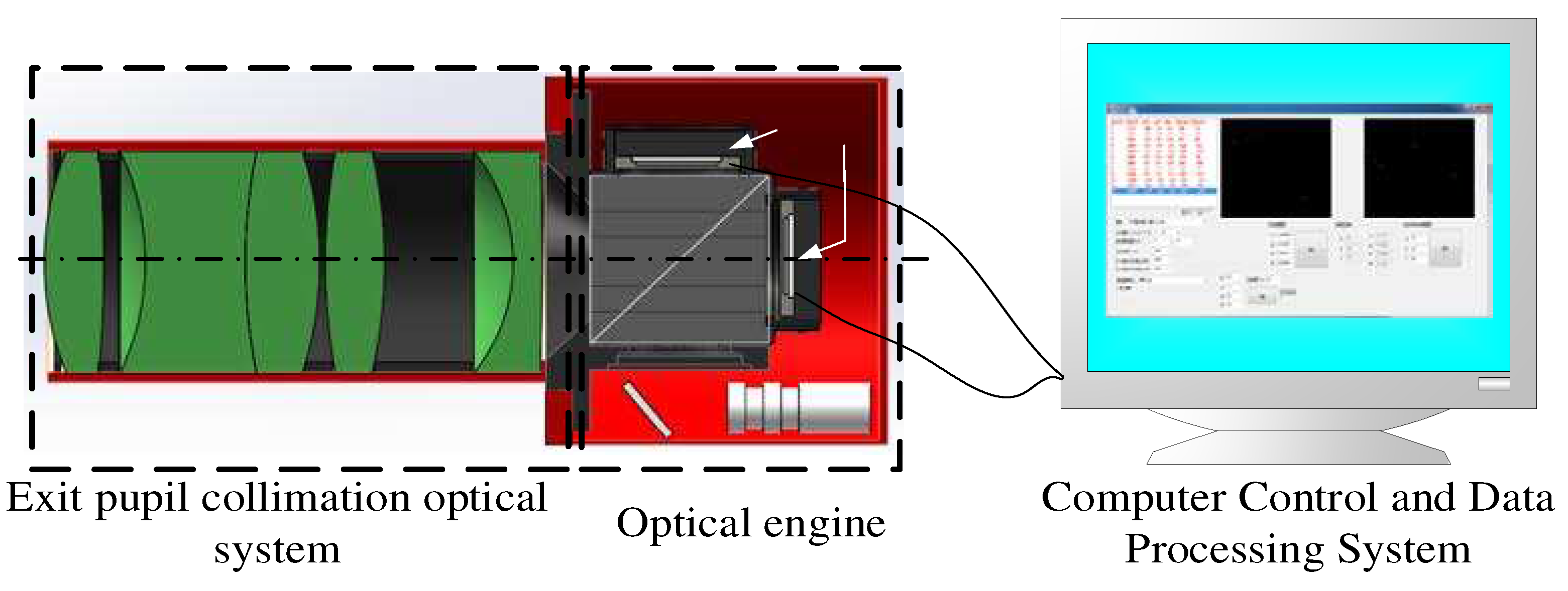
The weak starlight simulation system mainly comprises a computer control and processing system, an optical engine, and an exit pupil collimation optical system (Figure. 1). The working principle of the system is similar to that of a projector. The star map image displayed by the liquid crystal on silicon (LCOS) in the optical engine is projected through the collimating optical system to simulate the infinity characteristics of the star map[11,12]. Among them, the optical engine can be regarded as a polarizer with optical multiplexing function.
Figure 1.
Composition diagram of weak starlight simulation system.
Under ideal conditions, there is no polarization effect in the system. The position of each star point in the simulated star map is determined by its gray energy center. The gray energy distribution of the star point can be expressed as follows[13,14,15]:
where A represents the gray energy coefficient, σ represents the gaussian radius, and (xi,yi) represents the energy center coordinates of the star point.
Under real conditions, there is polarization effect in the system. The grayscale distribution g1(xi,yi) of the star point with the connotation of stray light can be expressed as follows:
where Δh(xi,yi) represents the gray level corresponding to the nonimaging stray light, and ∆x and ∆y represent the offset of the simulated star point position along two axes caused by the stray light.
A comparison of Eqs. (1) and (2) shows that the position of the simulated star will deviate from the theoretical value owing to the introduction of polarization effect. Therefore, to improve the simulation accuracy of star position, it is essential to analyze the cause of the polarization effect and determine a mechanism to suppress it.
2.2. Causes of Polarization Effect of Optical Engine and Its Suppression Mechanism
The effect of the optical engine on the polarization state of the incident light can be quantitatively analyzed using the Jones matrix multiplication method. Because the film in the optical engine is the main factor affecting the polarization state of the incident light, deriving a mathematical model of the incident light aperture angle, the polarization parameters of the optical engine film, and the polarization state of the outgoing light is essential.
The Jones matrix of the optical engine film can be expressed as follows[16]:
where φ represents the aperture angle of the incident light corresponding to the point on the axis of the collimating optical system. Tp and Ts represent the transmittance of P-polarized and S-polarized light in the transmitted light field. Δ = (δs + δp)/2 represents the average phase, and D = δs − δp represents the phase difference.
To determine the influence of the polarization effect of the optical engine film on the incident light, the vibration direction of the incident light is assumed to be along the x-axis. The polarization state of the outgoing light can then be expressed as follows:
As can be seen from Eq. (4), for the transmitted light path of the optical engine, the polarization state of the outgoing light will deviate from the theoretical value under the joint action of φ, Ts, Tp, and D. Moreover, because φ is a system parameter and is never zero, the target values of Tp, Ts, and D should be determined to ensure that the polarization state of the outgoing light does not deviate from the theoretical value.
If only the phase difference is considered, then T = Ts = Tp; accordingly, Eq. (4) simplifies to
Equation (5) shows that the transmittance T will not change the polarization state of the outgoing light. When D gradually approaches zero, the polarization state of the outgoing light approaches the polarization state of the incident light, which effectively inhibits the change in the polarization state caused by oblique incidence.
If only the influence of transmittance on the polarization state of the outgoing light is considered, then D = 0 and Eq. (4) simplifies to
where R = (Tp − Ts)/(Tp + Ts) represents the transmittance attenuation. The abovementioned formula indicates that when the difference Tp − Ts increases, the transmittance attenuation (Tp − Ts)/(Tp + Ts) increases and the polarization state of the outgoing light changes drastically. If Tp = Ts, the polarization state of the outgoing light approaches the polarization state of the incident light, inhibiting the changes in the polarization state caused by oblique incidence.
The aforementioned analysis shows that when the incident light has a certain aperture angle, the vibration state of the corresponding outgoing light is ellipsoidal after being deflected by the optical engine. Therefore, when the outgoing light passes through the polarizer, the vibration component parallel to the optical axis is no longer absorbed, resulting in stray light.
Therefore, to suppress the polarization effect of the optical engine and thereby inhibit the generation of stray light, the polarization parameters of the optical engine film should be D = 0 and R = 0 at the same time under ideal conditions.
3. Optimization Mechanism of Polarization Balance of Optical Engine
3.1. Derivation of Screening Conditions
To determine the relation between star position simulation accuracy and optical engine film parameters, a mathematical model of star position simulation accuracy and optical engine film polarization parameters was established by considering the extinction ratio as a link[17,18]. The relation between the extinction ratio k and the polarization parameters Rs and Ts of the optical engine film can be expressed as
In Eq. (7), ε represents the extinction ratio of the polarizer in the optical engine, Ts and Rs represent the transmittance of S-polarized light and P-polarized light emitted from the optical engine, respectively. φ represents the aperture angle of the incident light, and γ represents the space angle of the incident light.
The star point simulated by the weak starlight simulation system is usually represented by the 3 × 3 pixel primitive on the LCOS. Because the energy ratio of the edge pixel exerts the greatest influence on the energy center of the simulated star point, the relation between the extinction ratio k and the stray light gray scale mi when all the stray light converges at the edge point is
Based on the centroid formula, the relation between the optical engine extinction ratio k and the target value θ of the star position simulation accuracy is
where xi + 1 represents the horizontal coordinate of the position of the edge point of the simulated star point, xi represents the horizontal coordinate of the position of the simulated star point, and f' represents the focal length of the optical system. Similarly, the relationship between θ, the simulated star edge position ordinate yi + 1, and the simulated star position ordinate yi can be calculated. The maximum value of k is considered as the screening condition of the optical engine film.
Under the influence of the polarization film of the optical engine, the polarization states of the incident light with different incident aperture angles and azimuth angles are different in each part of the pupil plane after exiting the optical engine. Therefore, the optimization can be accurately estimated by determining the polarization states of the sampling points (i, j) at different positions on the pupil plane.
Based on the calculation concept of the weighted evaluation function in the least squares algorithm, the polarization-balance evaluation function model of the films at different positions on the pupil plane is derived. The model is expressed as
where D(i,j) and R(i,j) represent the current values of transmittance attenuation and phase delay, respectively, corresponding to the current pupil sampling point; ΔD(i,j) and ΔR(i,j) represent the tolerances for transmittance attenuation and phase delay; yd and yr, represent the weights of the transmittance attenuation and phase delay, respectively; m and n represent the number of sampling points in the x and y directions on the pupil, respectively; and and represent the optimization target of transmittance attenuation and phase delay, respectively.
3.2. Optimization Process and Results
Figure 2 shows the polarization-balance optimization process of the optical engine thin film. Aiming at D = R = 0, the initial film expression selected is G|HLHLH|G, where G represents the substrate glass; H and L represent materials with high and low refractive indices, respectively. In particular, ZnS with a refractive index of 2.36 was selected as the material with a high refractive index (H), Ag with a refractive index of 0.055 was selected as the material with a low refractive index (L), the thickness was , and the central wavelength was set as 550 nm.
To increase the diversity of the films to be optimized, the film thickness was considered as the optimization variable in the optimization process and the number of films to be optimized was increased to 100 using crossover and mutation operations in the genetic algorithm. During the mutation operation, the film thickness assignment range was set to 3–5 times the minimum film layer thickness.
The composition of the optimized polarization-balanced film is shown in Table 1.
Figure 3 shows the polarization-balanced optical engine thin film binomial attenuation and phase delay curves. The figure shows that the binomial attenuation and phase delay exhibit a positive correlation with the aperture angle of the incident light. When the aperture angle of the incident light is <8°, the corresponding full-band binomial attenuation is <0.001 and the phase delay is <1°, which satisfies the optimization objective.
Because the optical engine film is plated on a 45° inclined plane, the extinction ratio corresponding to different incident light space angles is asymmetrical when considering the same incident light aperture angle. Therefore, analyzing the extinction ratio corresponding to different space angles and different aperture angles is essential.
We set the aperture angle range of the incident light to be [0°–20°] and the space angle range to be [0°–180°] and subsequently calculated the optical engine extinction ratio distribution before and after the improvement. Figure 4 shows the calculation results. When considering the same incident light aperture angle, the extinction ratio is different for different space angles. When the aperture angle of the incident light is <8°, the minimum extinction ratio of the optical engine before the improvement is 149:1 and that of the polarization-balanced optical engine is 446 : 1. The stray light suppression ability of the polarization-balanced optical engine is improved nearly threefold.
4. Experiment
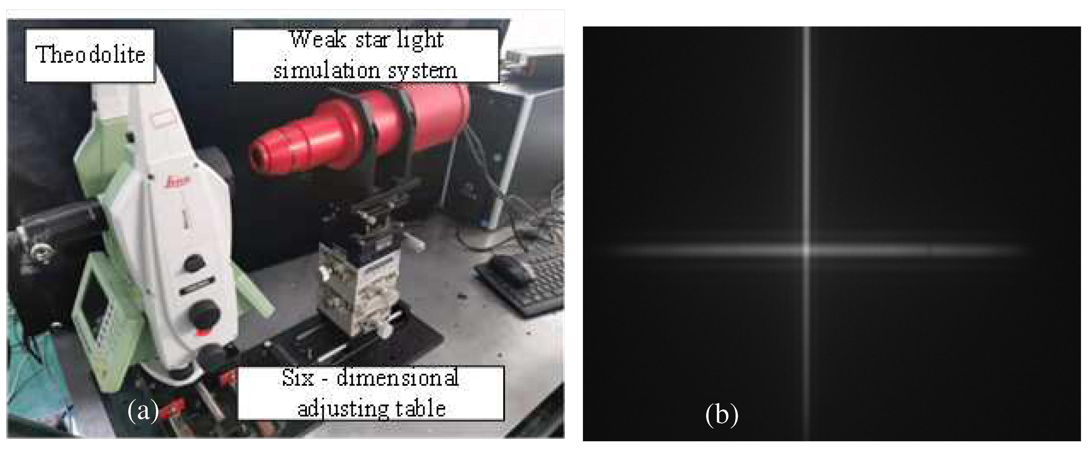
An experimental device was built for conducting the star position simulation accuracy test, as shown in Figure. 5(a). This device mainly comprises a weak star simulation system, theodolite, and six-dimensional adjustment table. The adopted exit pupil collimation optical system has a focal length f = 93.12 mm, an aperture D = 40 mm, and a single LCOS pixel size of 8 μm[19,20,21], as shown in Figure. 5(b).
As the star position in the center field of view is minimally affected by stray light and the corresponding extinction ratio is the optimal value, the extinction ratio corresponding to this position is selected as the critical screening condition. The boundary coordinates of the center field of view star point are (2.5, 2.5), the center position coordinates are (1.5, 1.5), and star position simulation accuracy target value θ=10". Substituting the aforementioned values into Eq. (9) shows that the screening conditions in the polarization-balance optimization mechanism of the optical engine thin film should satisfy k > 251:1.
Simultaneously, to ensure the optimization rate, m = n = 9, weight yd = yr = 1, the initial and are set to 2%. We then gradually reduce the tolerance until and during the optimization process.
Because the glass material of the optical engine does not undergo changes before and after the improvement, the image quality is not affected; therefore, the same external collimating optical system of the exit pupil can be used for comparative experiments.
Figure 5.
Star position simulation accuracy test experimental device and image plane real shot: (a) star position simulation accuracy test device (b) image plane real shot map.
Figure 5.
Star position simulation accuracy test experimental device and image plane real shot: (a) star position simulation accuracy test device (b) image plane real shot map.
To generalize, the entire field of view is covered with a 13 × 13 grid version and the grid intersection points are used as simulation star points. The test results are shown in Figure 6(a) and (b). A comparison of the two Figures shows that when using the polarization-balanced optical engine, the simulation error of the star point position in the whole field of view is reduced by a factor of 1.64 from 15.99" to 9.76", which validates the proposed method.
5. Conclusions
To overcome the problem of the effect of nonimaging polarized stray light on the star position simulation accuracy in current weak starlight simulation systems, an optimization method involving the polarization balance of an optical engine thin film is proposed in this study. First, the results demonstrate that the polarization parameters of the optical engine thin film should satisfy D = 0 and R = 0 under ideal conditions, which is considered as the optimization objective. Next, the mathematical models of the optical engine extinction ratio, polarization parameters, and star position simulation accuracy are established. At the same time, extinction ratio k is used as the screening condition of optimization mechanism. Finally, the polarization-balance evaluation function of the optical engine is constructed using the pupil sampling point as the minimum evaluation unit. The simulation results reveal that when the aperture angle of the incident light is >8°, the corresponding full-band binomial attenuation is <0.001 and the phase delay is <1° ; and the stray light suppression is nearly threefold greater than those before the improvement of the optical engine film. The experimental results confirm that after the polarization-balance optimization of the optical engine, the simulation error of the star position in the full field of view decreases by a factor of 1.64 from 15.99" to 9.76", which validates our proposed method.
Author Contributions
Conceptualization, L. H. Wu ; methodology, L. H. Wu. and L. Sheng; software, S. C. Ou. and L. H. Wu.; validation, L. H. Wu.; formal analysis, L. H. Wu; investigation, L. H. Wu and J. R. Sun; resources, L. H. Wu; data curation, J. A. Wang ; writing—original draft preparation, L. H. Wu; writing—review and editing, S. C. Ou; visualization, X.Y.; supervision, L. Sheng ; project administration, L. H. Wu.; funding acquisition, L. H. Wu. All authors have read and agreed to the published version of the manuscript.
Funding
This research was funded by Natural Science Research of Jiangsu Higher Education Institutions of China, grant number 23KJB140002 and23KJB460001. The APC was exempted by the publisher MDPI.
Institutional Review Board Statement
Not applicable.
Informed Consent Statement
Not applicable.
Data Availability Statement
Not applicable.
Conflicts of Interest
The authors declare no conflict of interest.
References
- Y. Gan, C. H. Duan, G. D. Liu, B. G. Liu, F. D. Chen, B. H. Lu. Continuous dynamic measurement of frequency scanning interferometry based on motion phase synchronization compensation and calibration. Opt. Express 2023, 31, 30974–30992. [Google Scholar] [CrossRef] [PubMed]
- Y. Mao, W. Ren, Y. Luo, Z. J. Li. Optimal Design Based on Closed-Loop Fusion for Velocity Bandwidth Expansion of Optical Target Tracking System. Sensors 2019, 19, 133. [Google Scholar] [CrossRef] [PubMed]
- T. H. Zeng, J. Q. Zeng. The optical measurement speed of moving bodies and the observer's position effect. Phys. Essays 2023, 36, 94–99. [Google Scholar] [CrossRef]
- Y. H. Zhan, Y. Zheng, C.H. Li, R.P. Wang, Y. X. Zhu, Z. L. Chen. High-accuracy absolute positioning for the stationary planetary rover by integrating the star sensor and inclinometer. J. Field Robot. 2020, 37, 37,1063–1076. [Google Scholar]
- Y. Y. Li, X. Wei, J. Li, and G.Y. Wang. Imaging modeling and error analysis of the star sensor under rolling shutter exposure mode. Opt. Express 2021, 29, 15478–15496. [Google Scholar] [CrossRef]
- L. H. Wu, G. Y. Zhang, G. F. Sun, S. Liu, D. Xu, Y. Hu, J. J. Yang, H. J. Sun. Design of optical engines for stellar simulation systems with low extinction ratios. Opt. Commun. 2020, 463, 125453. [Google Scholar] [CrossRef]
- W. D. Wu, P. G. Han, M. Shi, F. F. Su, F. Q. Wu. Design and performance analysis of a single-unit polarizing beam-splitting prism based on negative refraction in a uniaxial crystal. Appl. Opt. 2019, 58, 7063–7066. [Google Scholar] [CrossRef]
- Y. L. Deng, X. J. Li, Y. F. Geng, X. M. Hong. Effect of nonpolarizing beam splitter on measurement error in heterodyne interferometric ellipsometers. Meas. Sci. Technol. 2012, 23, 085204–1. [Google Scholar] [CrossRef]
- C. Jiang, D. Yao, L. T. Meng, C. H. Yan, and H. H. Shen. Suppressing the polarization aberrations by combining reflection and refraction optical groups. Opt. Express 2022, 30, 41847–41861. [Google Scholar] [CrossRef] [PubMed]
- E. Z. Li, Y. Q. Li, Y. Liu, K. Liu, Y. Y. Sun, and P. Z. Wei. Rigorous imaging-based measurement method of polarization aberration in hyper-numerical aperture projection optics. Opt. Express 2021, 29, 20872–20888. [Google Scholar] [CrossRef]
- D. S. R. Cardoso, B. R. Alves, B. Simone, C. Chantal. A review of balancing methods for satellite simulators. Acta Astronaut. 2021, 187, 537–545. [Google Scholar] [CrossRef]
- G. X. Li, L. Y. Wang, R. Zheng, X. Yu, Y. Ma, X. Liu, B. Liu. Research on Partitioning Algorithm Based on Dynamic Star Simulator Guide Star Catalog. IEEE Access 2021, 9, 54663–54670. [Google Scholar] [CrossRef]
- S. Wang, W. X. Chen, M. Chen, Y. W. Zhou. Maximum likelihood estimation of the parameters of the inverse Gaussian distribution using maximum rank set sampling with unequal samples. Math. Popul. Stud. 2023, 30, 1–21. [Google Scholar] [CrossRef]
- B. Samadrita, J. Nabakumar. Estimating reliability parameters for inverse Gaussian distributions under complete and progressively type-II censored samples. Qual. Technol. Quant. Manag. 2023, 20, 334–359. [Google Scholar] [CrossRef]
- S. Ayesha, V. Masilamani. A robust multiplicative watermarking technique for digital images in curvelet domain using normal inverse Gaussian distribution. Multimed. Tools Appl. 2022, 82, 9223–9241. [Google Scholar]
- L. H. Wu, G. Y. Zhang, G. F. Sun, S. Liu, S. Z. Yang, J. J. Yang, Z. K. Yun, D. X. Zhao, J. L. Sun, D. Zhao. Optical engine optimisation for faint starlight simulation systems. Opt. Commun. 2020, 471, 125833. [Google Scholar]
- J. H. Lee and K. Hoon. Receiver sensitivity of type-I return-to-zero signals having finite extinction ratios. Opt. Express 2023, 31, 13724–13738. [Google Scholar] [CrossRef] [PubMed]
- Y. Liu, Y. Dong, Y. Xu, B. Zhang, and Y. Ni. Broadband and high extinction ratio TE-pass/TM-stop polarizer at 850 nm using chirped subwavelength gratings. Appl. Opt. 2022, 61, 580–587. [Google Scholar] [CrossRef] [PubMed]
- S. f. Xu,J. Wang, W. W. Zou. Optical Convolutional Neural Network With WDM-Based Optical Patching and Microring Weighting Banks. IEEE Photonics Technol. Lett. 2021, 33, 89–92. [Google Scholar] [CrossRef]
- H. Zhou, L. Zeng. Optical mosaic method for orthogonally crossed gratings by utilizing information about both main periodic directions simultaneously. Opt. Commun. 2017, 385, 181–187. [Google Scholar] [CrossRef]
- Sarkar, B. N. Sharma, M. Saxena, N. Thapa, A. Kumar, H. K. Dave, S. S. Sarkar. Development of method for active alignment of multiple time delay and integration detectors in the optically butted focal plane assembly of high-resolution spaceborne imaging systems. J. Appl. Remote Sens. 2017, 12, 034003. [Google Scholar]
Figure 2.
Optimization process of polarization balance of optical engine thin film.
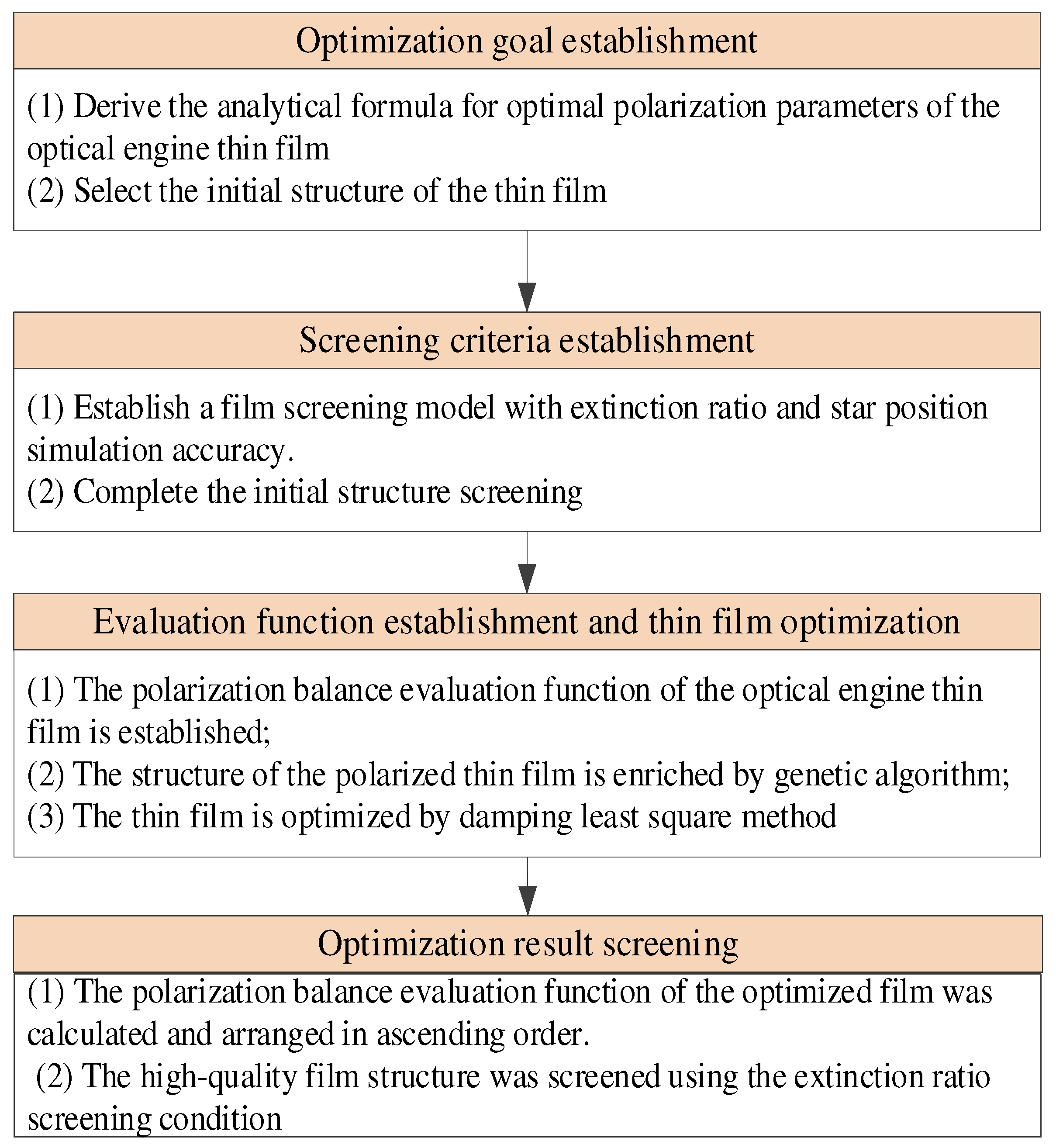
Figure 3.
Polarization-balanced optical engine film (a) binomial attenuation curve and (b) phase delay curve.
Figure 3.
Polarization-balanced optical engine film (a) binomial attenuation curve and (b) phase delay curve.
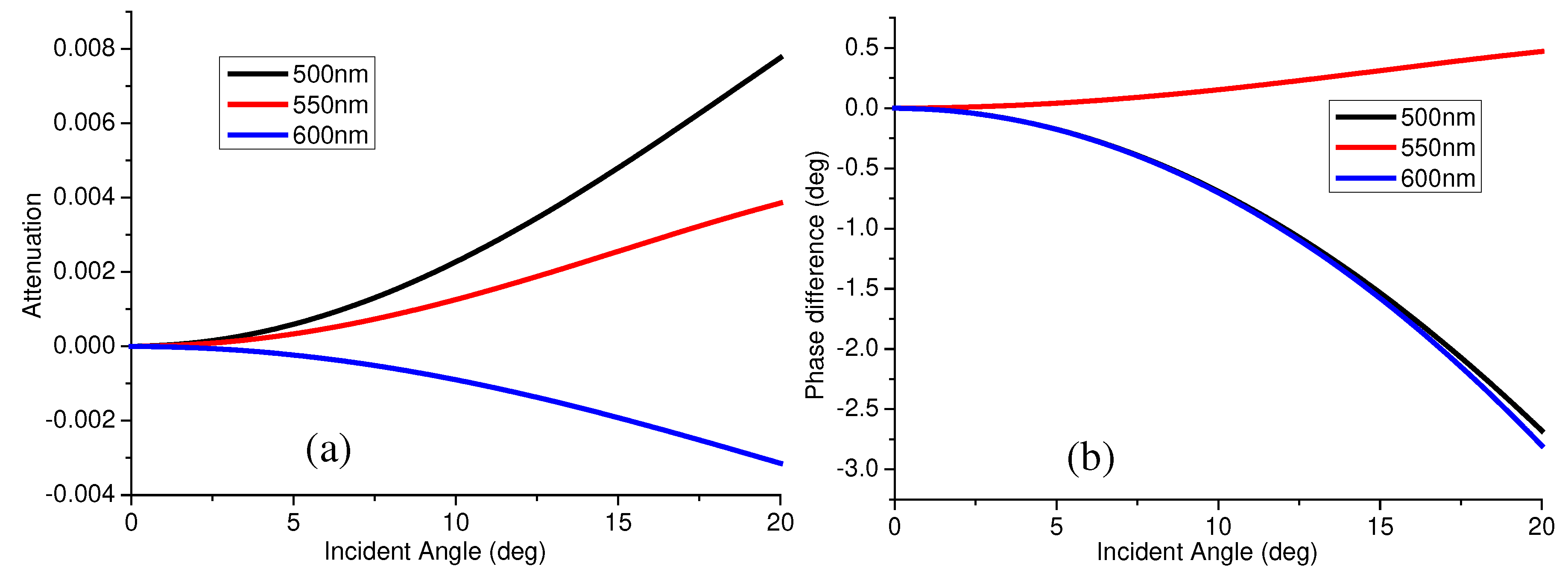
Figure 4.
Optical engine extinction ratio distribution before and after improvement: (a) Extinction ratio distribution for the existing optical engine (b) extinction ratio distribution for the polarization-balanced optical engine.
Figure 4.
Optical engine extinction ratio distribution before and after improvement: (a) Extinction ratio distribution for the existing optical engine (b) extinction ratio distribution for the polarization-balanced optical engine.
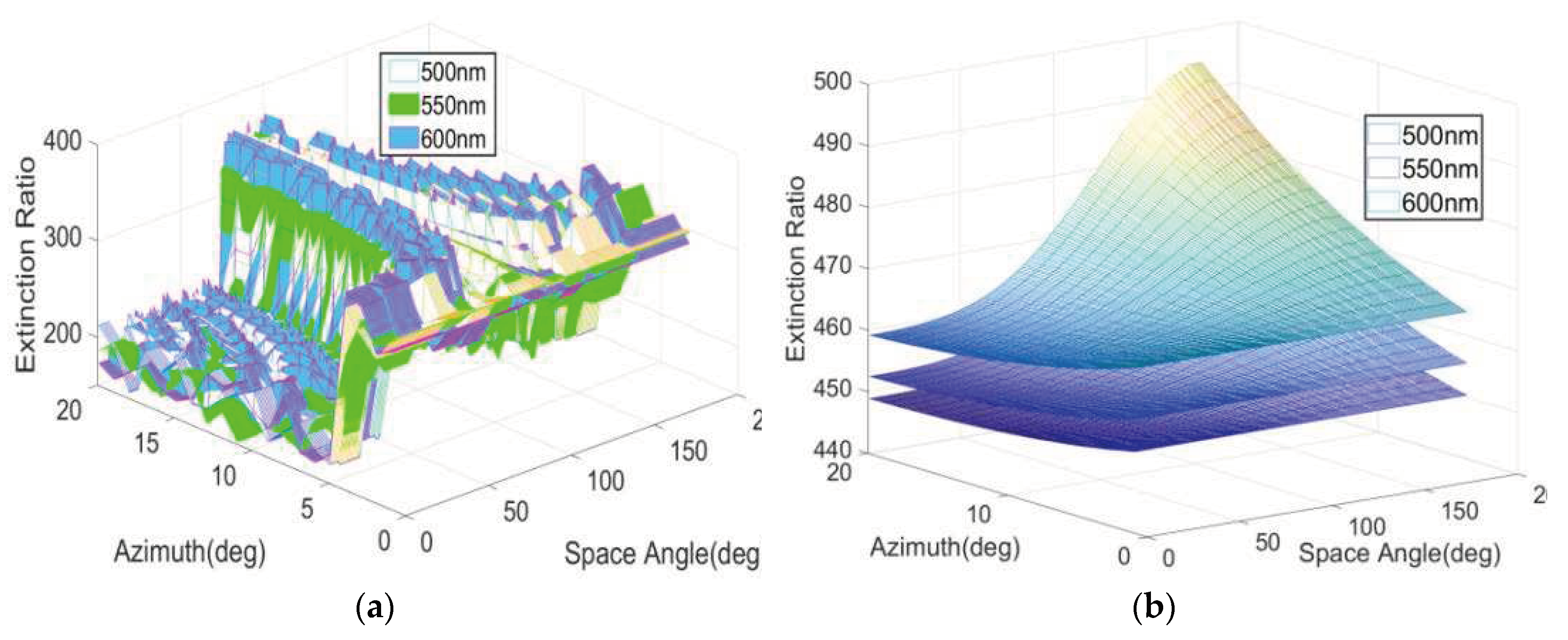
Figure 6.
Comparison of test results of position error of corresponding sampling points before and after adopting improved optical engine: (a) Test result of sampling point position error corresponding to the optical engine before the improvement. (b) Same as panel (a) but after the improvement.
Figure 6.
Comparison of test results of position error of corresponding sampling points before and after adopting improved optical engine: (a) Test result of sampling point position error corresponding to the optical engine before the improvement. (b) Same as panel (a) but after the improvement.
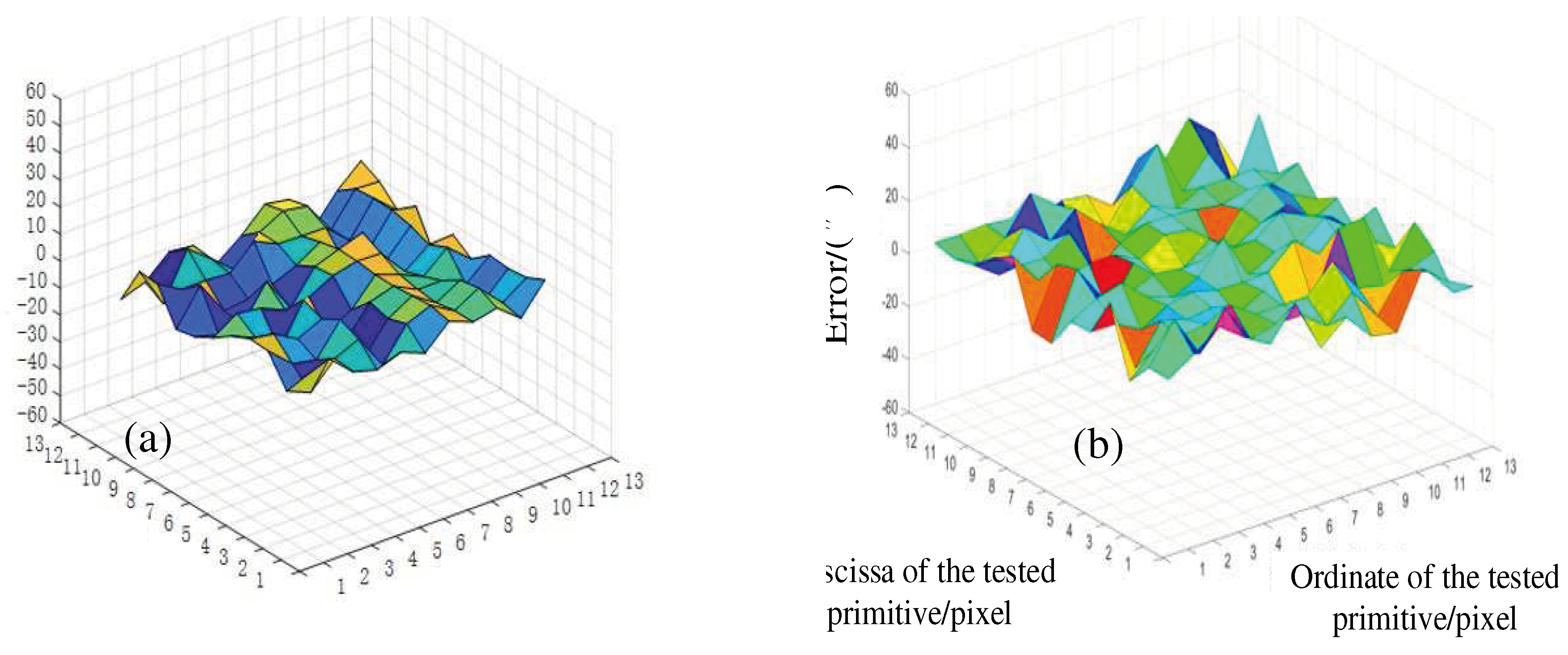

Table 1.
Results of optimization of polarization-balanced film.
| Materials | Refractive index | Optical thickness |
|---|---|---|
| Glass | 1.51 | / |
| ZnS | 2.36 | 0.335 |
| Ag | 0.55 | 0.0018 |
| ZnS | 2.36 | 0.179 |
| Ag | 0.55 | 0.002 |
| ZnS | 2.36 | 0.421 |
| Glass | 1.51 | / |
Disclaimer/Publisher’s Note: The statements, opinions and data contained in all publications are solely those of the individual author(s) and contributor(s) and not of MDPI and/or the editor(s). MDPI and/or the editor(s) disclaim responsibility for any injury to people or property resulting from any ideas, methods, instructions or products referred to in the content. |
© 2023 by the authors. Licensee MDPI, Basel, Switzerland. This article is an open access article distributed under the terms and conditions of the Creative Commons Attribution (CC BY) license (http://creativecommons.org/licenses/by/4.0/).
Copyright: This open access article is published under a Creative Commons CC BY 4.0 license, which permit the free download, distribution, and reuse, provided that the author and preprint are cited in any reuse.


