1. Introduction
Accidents involving pedestrians and cyclists, known as vulnerable road users (VRU) by the international convention, are disproportionately likely to result in serious or fatal injuries and play an important role in accident reconstruction. One possible scenario in the inner-city environment is an accident between right-turning commercial vehicles and parallel pedestrian or bicycle traffic [
1,
2]. Due to the elevated driver's seat position and the non-full-surface glazing of the driver's cabs, areas near the commercial vehicle cannot be easily seen by the driver. These areas are called blind-spots. In order to minimize this, the EU Directive 71/127/EEC [
3] has prescribed several complementary mirror systems for commercial vehicles since 1971. As an additional problem, a heavy commercial vehicle's driver must pay attention to various potentially critical areas simultaneously, especially when turning in a limited space in an inner-city environment. It is often impossible to concentrate fully on a specific potential danger zone during the entire turning process. Cyclists, in particular, move at a comparatively high speed and may only be perceptible for a short time in one of the exterior mirrors and can therefore be overlooked by the commercial vehicle's driver [
2,
4,
5,
6,
7].
In order to compensate for this problem and thus noticeably reduce the number of traffic accidents, Regulation EU 2019/2144 of 27.11.2019 [
8] successively introduced various driver assistance systems as mandatory equipment for newly type-approved or newly registered vehicles. In particular, to improve the perceptibility of VRU for commercial vehicles with a maximum permissible mass of more than 3.5 t, a so-called blind spot assistant is required from 06.07.2022 for newly type-approved vehicles and from 07.07.2024 for newly registered vehicles. Due to the increased risk potential because of their high speed, cyclists are explicitly targeted. However, the functionality of the blind spot assistance system also includes comparable road users, such as users of small electric vehicles and pedestrians. The technical characteristics of this assistance system and the required test methods are described in UN-ECE R151 of 25.09.2020 [
9] and summarized in the following paragraph.
Two escalation levels are defined here: The information signal is intended to alert the commercial vehicle driver to a bicycle riding on the right-hand side of the vehicle in the potential danger zone when a turning maneuver is initiated. It is said to be an optical signal appearing in the right-hand area of the vehicle cabin. The warning signal must be activated when the system detects an imminent collision with a bicycle in the danger zone if the driver does not react using an appropriate steering angle or an operation of the direction indicator. This can be an optical, acoustic, haptic signal, or a combination of them. While this optical-acoustic warning signal may be switched off manually or automatically, the visual information signal may only be deactivated automatically in case of a system malfunction or contamination of the sensors.
The assistance system must work in a self-speed range between 0 km/h and 30 km/h. On the one hand, it is intended to warn of a cyclist crossing in front of the vehicle in an area that is not directly visible when the vehicle is stationary. On the other hand, a warning signal should be issued if a bicycle moves at a speed between 5 km/h and 20 km/h on the right side of the vehicle. The detection area should be in a lateral corridor between 0.9 m and 4.25 m to the right of the vehicle, which extends to 7.00 m in front of and 30.00 m behind the right front corner. In addition, it should be possible to perceive a bicycle at a lateral distance of 0.25 m to 0.90 m at the level of the foremost front wheel and to issue an information signal [
9]. Speeds in the unit km/h are given with an accuracy of 1 km/h, and two valid decimal places are given for distances in the unit m.
UN-ECE R151 defines two static and one dynamic test method, whereby only the timely occurrence of the information signal is assessed as a passing criterion. The warning signal, which indicates an imminent collision, is not considered [
9]. In the static test, the vehicle is at a standstill, while in the first test run, a bicycle approaches from the right at a speed of 5 km/h and a distance of 1.15 m in front of the vehicle. This must be detected and signaled by the assistance system at least 2.00 m before passing the right-hand front corner of the vehicle. In the second test procedure, the bicycle moves parallel from the rear to the front of the vehicle at a 20 km/h speed at 2.75 m from the right side. In this case, the assistance system must warn the driver at the latest when the bicycle is still 7.77 m behind the front of the vehicle. In the dynamic system tests, the vehicle passes through a corridor while a bicycle moves parallel to it on the right at a lateral distance of 1.25 m or 4.25 m. In addition to the variable lateral distance, alternating speeds of 10 km/h and 20 km/h are also specified for both the test vehicle and the bicycle. This results in different relative speed constellations between the vehicle and the detection object, which depict different traffic scenarios. The test is deemed to have been passed when the blind spot assistance system detects the bicycle at the latest in a certain constellation that depends on the driving speeds and warns the rider. Furthermore, no warning message may be induced when passing a traffic sign set up at the beginning of the driving corridor or when passing a stationary bicycle.
In addition to this EU regulation, the German Federal Ministry for Digital and Transport
(Bundesministerium für Digitales und Verkehr BMDV) launched a funding program in Germany in 2019 for the voluntary retrofitting heavy commercial vehicles with a blind spot assistance system to accelerate the spread of these systems among existing vehicles. In order for a retrofit assistance system to receive a general operating permit from the German Federal Motor Transport Authority
(Kraftfahrbundesamt KBA) and to be classified as eligible for funding in this program, it should meet the recommended test criteria published at the national level in the official section of the German state traffic journal (
Verkehrsblatt) 19/2018 [
1,
10]. Here, a lateral coverage area of the blind spot assistance system with a length of 6 m from the front edge of the vehicle and a width of 2.5 m from a lateral distance of 0.9 m to the vehicle is required[
11]. Furthermore, an amendment to § 9 of the German traffic regulations (
Straßenverkehrsordnung StVO) stipulates that a driver of a motor vehicle with a maximum permissible mass of more than 3.5 t in urban areas must drive at walking speed when turning right if there is a bicycle traffic driving straight ahead on or next to the carriageway or in the immediate area of turning with a cyclist crossing the carriageway pedestrian traffic is to be expected. The walking speed is not clearly defined in the StVO [
12], and there is also no binding decision of the German Federal Court of Justice, which the subordinate courts could use as a guide. The range set by the
General German Automobile Association (Allgemeiner Deutscher Automobil-Club ADAC) and the German district courts and higher courts ranges from about 7 km/h to less than 15 km/h [
13,
14].
If, despite the measures listed, a turning accident occurs, its course of events often must be clarified by forensic accident analysts [
15]. Of particular interest is often the clarification of the circumstances under which the driver of the road transport vehicle could have caused the accident. Since the blind spot assistance system is a pure warning system that does not actively interfere with the vehicle's driving dynamics and is therefore intended to brake it independently, it must be analyzed whether or when the driver was visually or acoustically alerted to the VRU by the system while approaching the collision site in order to direct his gaze into the relevant mirror and to increase the urgency for braking action.
For this purpose, however, the accident analyst must have access to the connecting facts as to when and how the system warned the driver. UN-ECE R160 [
16], in its current form, prescribes the event data recorder (EDR) for recording accident-related data only for vehicles up to a maximum permissible mass of 3.5 t. According to the current UN-ECE R160, the data set does not contain any references to the activities of Advanced Driver- Assistance Systems (ADAS)[
16]. Accordingly, in commercial vehicles, in particular, there are no digital traces of ADAS activities available that would be stored in the event of a collision and could be read by independent third parties. Suppose the possible influence of ADAS and autonomous driving functions of the commercial vehicle involved in the accident is to be included in the technical assessment. In that case, this can only be done through tests. The legal perspective on the influence of driver assistance systems and autonomous driving functions on an accident has yet to be clarified. In January 2023, Working Group III – AI Liability in Road Traffic / Liability in Autonomous Driving of the 61
st German Traffic Court Conference in Goslar drew up the following recommendation: Until further notice, strict liability towards the injured party in the accident should remain fully with the vehicle owner's liability insurance in the first step. Since it can nevertheless be assumed that in the future, more system errors will lead to accidents instead of human driving errors, product liability is intended to enable liability insurance companies to make recourse claims against the vehicle manufacturer in the second step [
17,
18].
Such product liability claims are only possible if a technical expert opinion can prove a significant influence of the ADAS interventions on the course of the accident. Forensic experts must have the necessary connecting facts, as neither digital traces nor basic data from experiments are available. Previous experimental investigations, particularly on blind spot assistance systems, make only qualitative statements on fulfilling national and European test criteria and can only be used to a limited extent for forensic accident analysis [
1,
10,
19].
Throughout this article, numerous experiments were carried out with a wide variety of constellations to identify a relevant parameter set for the pre-crash driving behavior and avoidability analysis during accident reconstruction. From this, a method is derived as to how the turning assistance system should be integrated into the pre-crash and avoidability simulations in the future.
In 2019 and 2021, the ADAC took the above-mentioned national funding program of the Federal Ministry for Digital and Transport as an opportunity to qualitatively review the performance and functionality of various retrofit assistance systems available on the market in the sense of a consumer protection test by the applicable regulations. The tested systems differ considerably in terms of the environment sensors used, the activation strategy, and the warning strategy [
1,
10,
19]. Selected systems were subjected to static and dynamic tests by the ADAC by the BMVI recommendations and UN-ECE R 151 – in some cases, in a slightly modified or simplified form.
As a core result of the ADAC-tests, it should be noted that in the case of an inner-city right-turn at walking speed by the road traffic regulations and with the direction indicator activated at an early stage, all tested blind spot assistance systems can develop their full performance by the standard specifications. Nevertheless, sufficient shortcomings of the [
1,
10,
19] assistance systems were found in the ADAC test series that it is not to be expected that turning accidents in real traffic can be avoided and that a closer look from an accident analysis point of view is expedient [
1,
10,
19].
2. Materials and Methods
In order to be able to investigate the extent to which blind spot control systems can make a real contribution to the prevention of right-turn accidents test series were carried out. Another aim was to explore how such an assistance system can be integrated into the reconstruction of the accident sequence and the avoidability analysis. First, the relevant influencing variables on the behavior of the blind spot assistance systems were to be identified. Secondly, data should be generated on the timing of the warnings before a collision and on the relative constellation of the vehicle and the vulnerable road user at the time of warning. To ensure comparability and plausibility of the qualitative results, the test setups were very closely based on the ADAC test series [
1,
10,
19] based on the specifications of UN-ECE R151.
2.1. Experimental design
Two static and two dynamic test setups were used, whereby this designation refers to the commercial vehicle since the VRUs were in motion in any case. In static tests the commercial vehicle was turned on with automatic transmission in mode “drive”. The vehicle was hold in position by the driver using the service brake. The parking brake was not used to ensure that the ADAS were working.
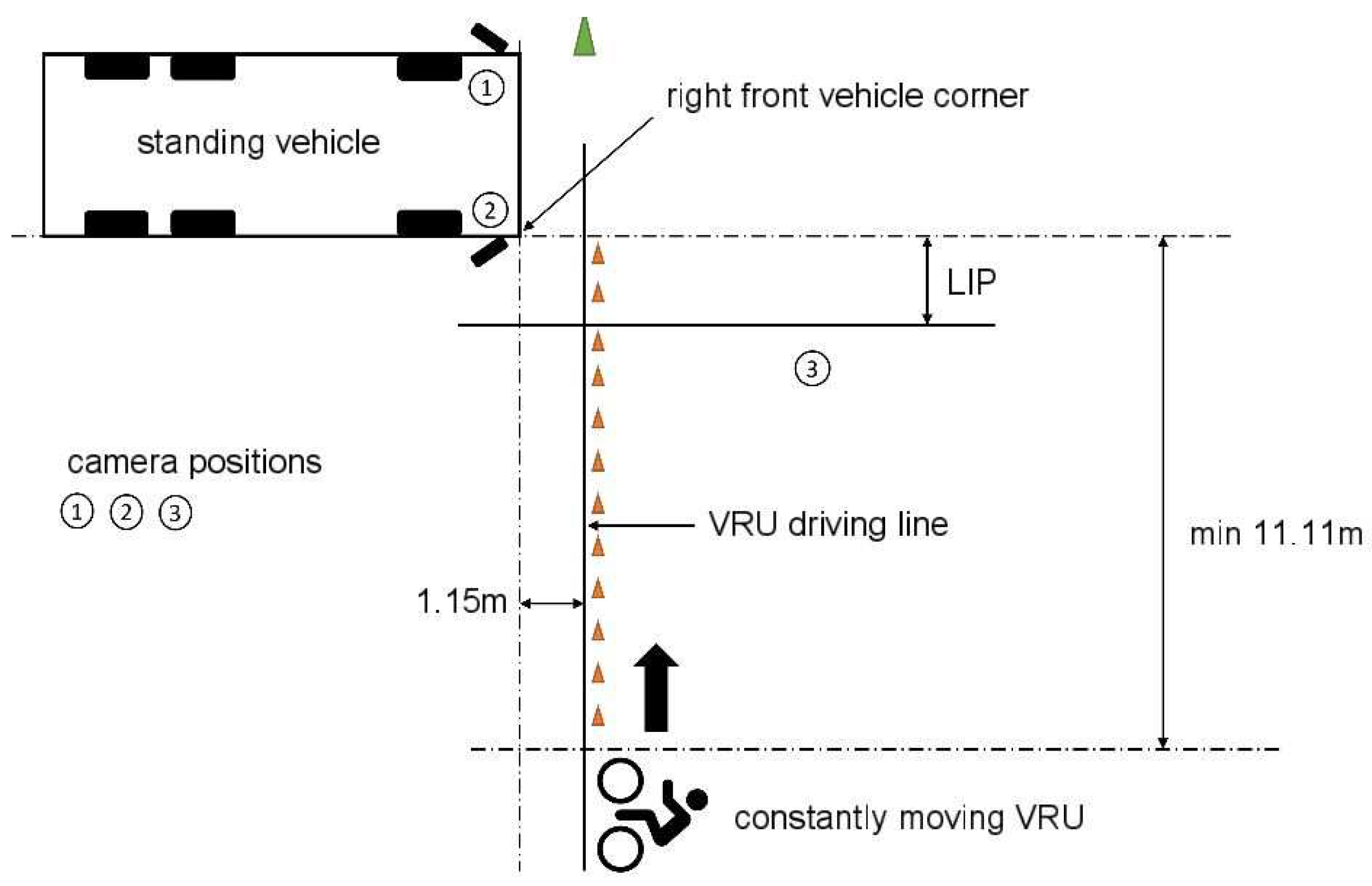
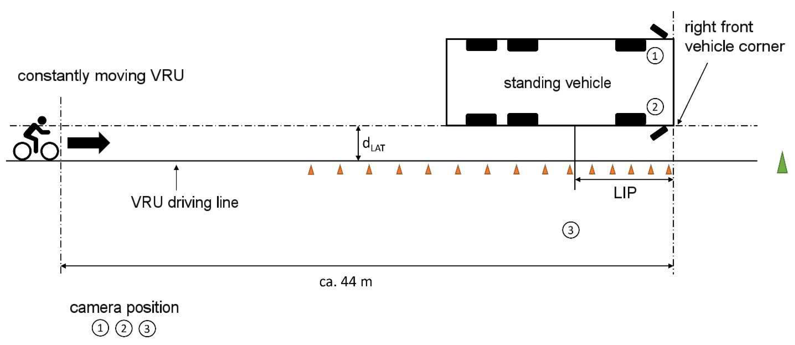
The test setup for the first static test with a VRU crossing in front of the vehicle was taken from UN-ECE R151, as shown in
Figure 1 below [
9] and supplemented by further test speeds. The Figure explains especially the distances between the VRU driving line and the front of the vehicle and the start distance of the VRU.
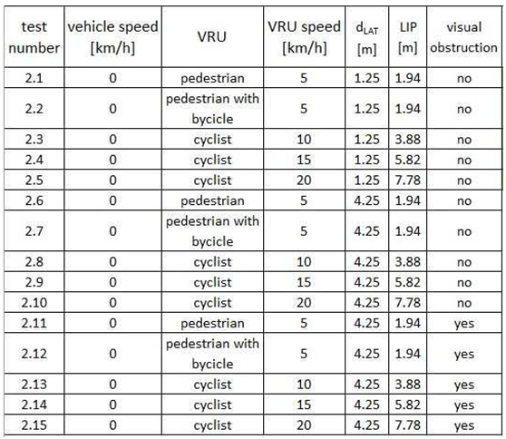
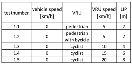
The tests were conducted at VRU speeds of 5 km/h, 10 km/h, 15 km/h, and 20 km/h as described in
Table 1. The speed measurement was carried out by a speedometer mounted on the bicycle, which determines the driving speed from the wheel speed to an accuracy of 1 km/h. In each case, the latest possible point in time – the so-called last information point (LIP) – was determined in a speed-adjusted manner at which the blind spot assistance system would have to point out the approaching VRU so that the commercial vehicle driver could safely avoid a collision due to a braking reaction. The LIP is given as a distance value measured between the VRU and the right front corner of the vehicle.
Figure 1.
Static experimental setup with VRU crossing the front of the commercial vehicle.
Figure 1.
Static experimental setup with VRU crossing the front of the commercial vehicle.
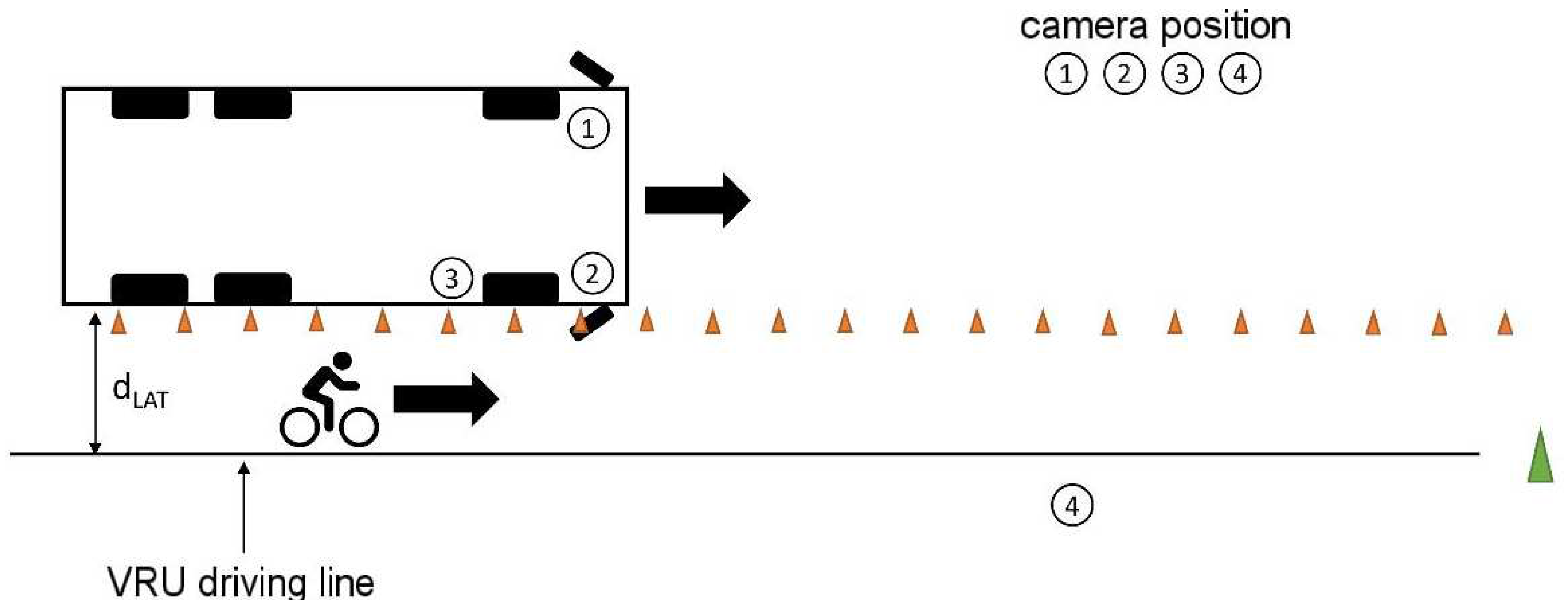
In the second static test described in
Figure 2, according to UN-ECE R151 [
9], a VRU moves parallel to the longitudinal axis of the commercial vehicle from rear to front along its right-hand side. In contrast to UN-ECE R151, two lateral distances of 1.25 m and 4.25 m (d
LAT in
Figure 2) were investigated in the tests. The VRU starts about 44 m behind the front of the commercial vehicle to make sure that the start point is out of the detection range of the sensor systems.
As in the first test setting, different speeds of the VRU were used as shown in
Table 2. The distances were determined with a tape measure symron-s sys20mt from
Tajima Tolls Glückstadt with an accuracy of 0.01 m and DAkkS-certificated calibration.
Furthermore, the tests were carried out with a lateral distance of 4.25 m in an additional passage with a visual obstruction by parked vehicles between the commercial vehicle and the VRU (shown as an example in
Figure 3, tests 2.11 to 2.15 in
Table 2). To make sure that the worst case scenario is tested, it was made sure that the cars were parked right in front of the sensors on the side of the commercial vehicle. The gaps between the cars were made as small as possible.
Table 2.
Test matrix static experiment with VRU driving parallel to the commercial vehicle.
Table 2.
Test matrix static experiment with VRU driving parallel to the commercial vehicle.
Similarly, and following the ADAC's investigations [
1,
10,
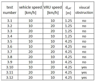
19], dynamic tests were carried out in which the commercial vehicle and VRU moved parallel to each other at different speed constellations with lateral distances of 1.25 m and 4.25 m, respectively as described in
Figure 4.
First, an equal driving speed of both vehicles of 10 km/h and 20 km/h respectively was investigated. Here both vehicles started together and the experiment began when both reached the test speed. Furthermore, reciprocal overtaking maneuvers were depicted, in which one road user with a speed of 20 km/h overtook the other one moving with a speed of 10 km/h.
Table 3.
Test matrix dynamic test with the parallel movement of commercial vehicle and VRU.
Table 3.
Test matrix dynamic test with the parallel movement of commercial vehicle and VRU.
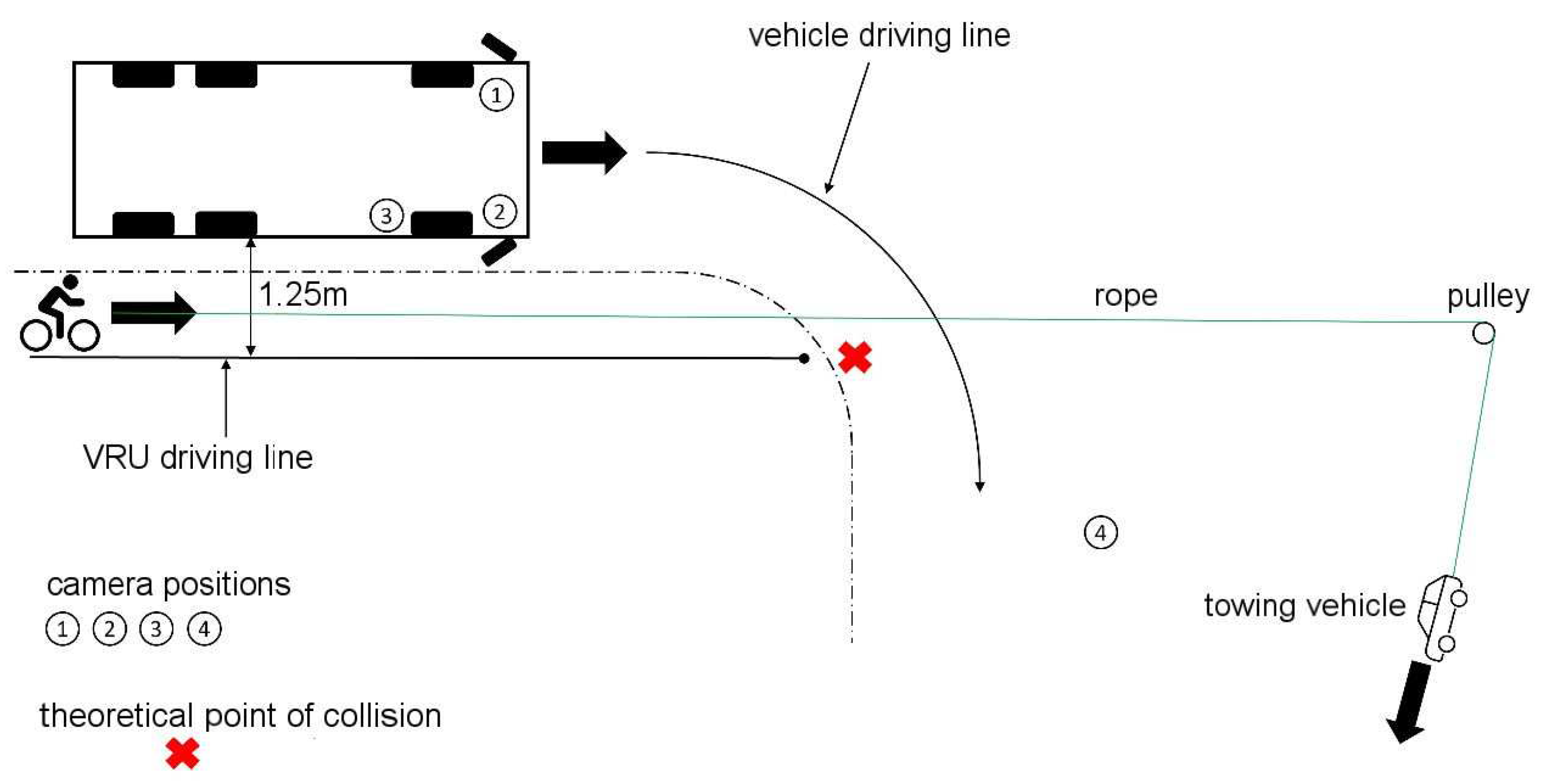
In the dynamic tests described above, based on UN-ECE R151, no intersection of the commercial vehicle and VRU trajectories and, thus, no immediate risk of collision was provoked. Accordingly, as intended, a maximum of the information signal from the turning assistance system can occur. For this reason, a further test setup has already been designed by the ADAC, which can also be used to provoke the occurrence of the warning signal of the blind spot assistance system. From an initially parallel movement of the commercial vehicle and VRU with a lateral distance of 1.25 m, the commercial vehicle turns right at a defined point. The VRU was represented by a bicycle dummy pulled by a test vehicle at a defined speed, as a collision between the two road users can occur without timely intervention by the commercial vehicle driver [
1,
10,
19].
Figure 5.
Dynamic experimental setup with the intersection of the movement corridors.
Figure 5.
Dynamic experimental setup with the intersection of the movement corridors.
As an additional test variable the right direction indicator of the commercial vehicle was activated in half of the test runs to find out if there is an influence on the sensitivity of the assistance system.
Table 4.
Test matrix dynamic experimental setup with the intersection of the movement corridors.
Table 4.
Test matrix dynamic experimental setup with the intersection of the movement corridors.
2.2. Test vehicles and blind spot assistance systems
The blind spot assistance systems currently available on the market use ultrasonic or radar sensors or camera-based object recognition algorithms for environment detection. Ultrasonic and radar sensors are based on the physical principle of time-of-flight measurement. Sound waves or electromagnetic waves are emitted and reflected by surrounding objects. The distance between the sensor and the object can be calculated from the known speed of sound or light and the elapsed time between emitting and receiving the wave signal.
Ultrasonic sensors can reliably detect objects over a distance of a few meters, almost regardless of their surface properties. Several sensors are required over the entire right side of the vehicle to cover the necessary detection range on a heavy commercial vehicle [
20,
21]. With the help of ultrasonic sensors, it is impossible to classify static and dynamic objects on the right-hand side of the road.
One advantage of radar technology over ultrasonic sensors is the significantly longer detection range. However, the decisive factor for use in a blind spot assistant is the ability to determine the speed of a detected object and thus classify it into static objects and moving road users. As a result, false positive events due to traffic signs or other static obstacles at the edge of the road can be better avoided with radar sensors [
20,
21]. Depending on the mounting height of the sensors, which is usually at the height of the vehicle's main frame below the body, the fields of view of both ultrasonic and radar sensors are limited by static obstacles such as parked vehicles [
20,
21]. The test vehicle used here was a Mercedes-Benz Actros 2545 (vehicle identification number W1T96302010442521) with a first registration date in July 2020 with an engine output of 330 kW and a gross vehicle weight of 26,000 kg with an S1R blind spot assistance system developed by Mercedes itself. Instead of conventional exterior mirror systems, the test vehicle was equipped with wide-angle cameras as a mirror replacement system, whose fields of view are displayed on screens inside the A-pillars.
In camera-based systems, a downstream software function identifies and classifies objects in the camera's field of view based on patterns and motion profiles stored in a database. The camera's image quality depends on the prevailing lighting conditions and weather conditions in a similar way to the human eye. This is where complementary infrared sensors can help. Atypical objects or movement patterns may not be detected or incorrectly classified by the evaluation software. The advantage is the usually high mounting position of the camera on the upper edge of the driver's cab, which allows a view over obstacles next to the vehicle [
20,
21]. For the tests, the ICA Turn-Assist AAS blind spot assistance system from the manufacturer AXION AG was used, which was mounted on a MAN TGM 18.290 with first registration in September 2021 (vehicle identification number WMAN38ZZ2MY418969) with an engine power of 213 kW and a gross vehicle weight of 18,000 kg. A supplementary camera monitor system (CMS) allows the driver to check the plausibility of warnings from Blind Spot Assist and to identify false positives as such [
20,
21]. Such a CMS from the manufacturer AXION AG was also attached to the MAN test vehicle.
2.3. Experimental area
The tests were conducted on the asphalted 60 m by 70 m outdoor test area of the CARISSMA Research Center of the Technical University of Ingolstadt which is described in Detail in [
22]. Permanently installed and mobile pulley systems are available on the site, which allow the movement of VRU dummies synchronized with the driving speed of the test vehicle via rope pull systems.
2.4. Test equipment
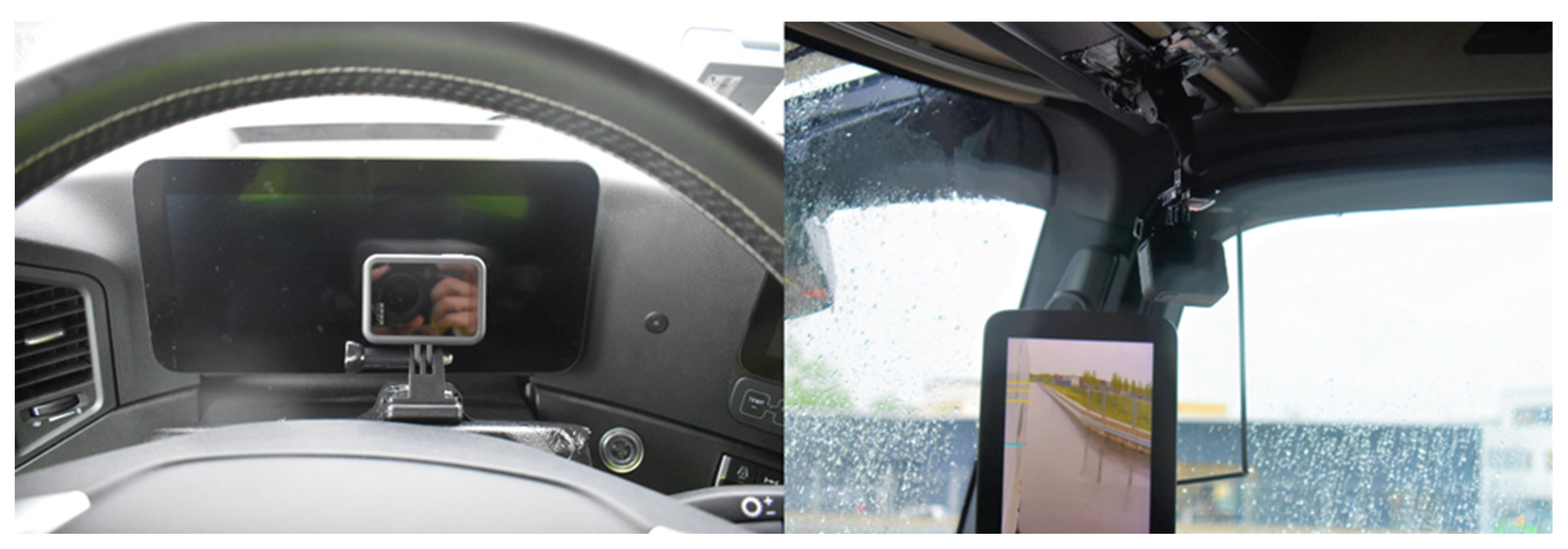
The experiments were recorded from several perspectives with video cameras in image and sound. For this purpose, several compact action cameras of the type HERO8 Black from the manufacturer GoPro Inc. from San Mateo (California, USA) were mounted in the driver's cab of the respective freight vehicle, which filmed the driver's perspective to the front, to the instrument cluster and the exterior mirrors on the right A-pillar. Another GoPro HERO8 Black was attached to the outside of the cab to record the movement of the VRU parallel to the road vehicle. In addition, the test sequence was filmed by two tripod mounted XA30 video cameras from the manufacturer CANON from Tokyo (Japan) from the perspectives shown in the test sketches above. Action cameras were placed in front of the instrument display and the a-post inside the trucks cabin and outside at the right side of the cabin filming the VRU. The positions of the video cameras where chosen to film the moving of the VRU from the front and in a 90°-angle from the side.
To synchronize the videos, a horn signal was played at the beginning of each experiment, the characteristic signature of which could be identified in the audiotracks of each video. The synchronization and post-processing of the videos were carried out with the open-access software Shortcut from the manufacturer Meltytech LLC.
Figure 6.
Mounting action cameras to record instrument cluster display and mirror fields of view.
Figure 6.
Mounting action cameras to record instrument cluster display and mirror fields of view.
Furthermore, with the help of a 2D data logger from 2D-Debus & Diebold Messsysteme GmbH from Karlsruhe, the position, speed and acceleration, and deceleration behavior of the goods road vehicle were recorded with a measurement accuracy of +/- 2%. The device was mounted on the dashboard and calibrated. The measurement data exported in CSV format was evaluated with the software "WinARace" belonging to the measuring device.
As a VRU for the experimental setups 1,2 and 3 a real person was used as a pedestrian or riding a black mountain e-bike from rockrider . The person had a height of about 1.75 m and was wearing dark clothes under a yellow warning vest. For experiment number 4 we used an EuroNCAP bicyclist target-dummy from 4activeSystems GmbH from Traboch, Austria.
As visual obstacle for test number 2 we used some available passenger cars with a height of at least 1.5 m. For the experiments we used a Madza 3, a Skoda Octavia and a Seat Ibiza.
3. Results
3.1. Static tests with crossing VRU
It was found that the radar-based blind spot assistance system of the Mercedes test vehicle was able to reliably detect the VRU approaching in front of the truck front from the right, regardless of the activity status of the right direction indicator. Up to a VRU approach speed of 5 km/h, the corresponding information signal was issued to the driver in good time before the LIP. This corresponds to the test criterion of UN-ECE R151. At higher VRU speeds, the information signal was only issued after the LIP, so that a timely avoidance reaction by the driver was no longer ensured.
The detection range of the camera-based blind spot assistance system of the MAN test vehicle does not cover the area in front of the truck, so that a VRU crossing in front of the truck front cannot be detected with this system. Although the area to the right of the truck is also visible to the driver for several meters in front of the front of the truck via the camera monitor system, there is no automated image evaluation here. Accordingly, no information or warning signal was triggered by the VRU crossing in front of the truck in any of the test runs.
3.2. Static tests with parallel moving VRU
The radar system of the Mercedes test vehicle was able to detect a VRU approaching from behind parallel to the longitudinal axis of the truck at a lateral distance of 1.25 m to 4.25 m in advance of the LIP, irrespective of the actuation state of the right-hand direction indicator, so that an information signal was issued to the driver. If there were parked vehicles between the radar sensors mounted on the side of the test vehicle and the VRU's line of movement as an obstacle to visibility, the VRU could not be detected by the assistance system at any time.
The camera-based blind spot assistance system of the MAN test vehicle reliably detected the VRU approaching from behind at a lateral distance of 1.25 m irrespective of the actuation of the right-hand direction indicator and was able to issue an information signal to the driver in good time before the LIP up to a test speed of 10 km/h. At higher test speeds, the information signal was only issued after the LIP and thus too late for the driver to react in time. At higher test speeds, the information signal did not occur until after the LIP and thus too late for the driver to react in time. At a lateral distance of 4.25 m between the movement line of the VRU and the right side of the truck, the VRU could not be detected by the blind spot assistance system of the MAN test vehicle. Upon close examination, it was found that the camera image displayed in the in-cab monitor covered a very large area to the right of the vehicle and the VRU was visible at an early stage at a distance of 4.25 m. The VRU was not detected by the blind spot assist system. However, the area actively monitored by the blind spot assistance system only has a width of up to 2.2 m maximum. At greater lateral distances, therefore, the only function of the camera-monitor system is to extend the indirect field of vision of the exterior mirrors. Consequently, the VRU could not be detected between the VRU motion line and the truck.
3.3. Dynamic tests with VRU moving in parallel
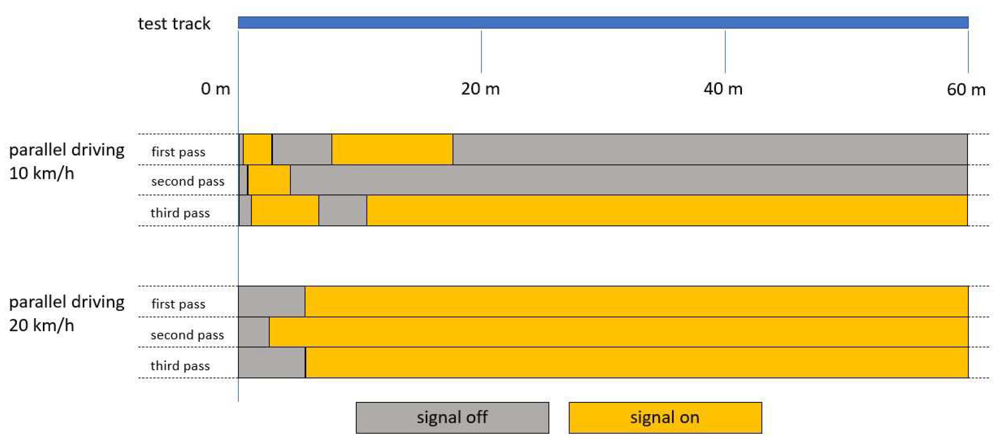
In the dynamic tests with a commercial vehicle and VRU moving in parallel without visual cover, the Mercedes test vehicle showed a speed-dependent response behavior of the blind spot assistance system. If the commercial vehicle overtook the VRU traveling at 10 km/h at a speed of 20 km/h, the information signal was triggered as soon as the VRU entered the detection range of the blind spot assistance system from the front. If the truck overtook the VRU traveling at 10 km/h at a speed of 20 km/h, the information signal was triggered as soon as the VRU entered the detection range of the blind spot assistance system from the front. If, on the other hand, the VRU overtook the truck at the opposite speed ratio, the information signal was triggered when the VRU entered the detection zone from behind. If both test participants were moving at the same speed of 10 km/h, an irregular response behavior was observed (see
Figure 7). Shortly after the start, the information signal was triggered and deactivated again after a few meters. Only in one of the three runs did the signal subsequently remain for the rest of the way. If the test was run at a speed of 20 km/h instead, it took longer for the signal to be activated, but the signal remained continuously until the end in all three runs.
When these tests were carried out with a visual obstacle between the right-hand side of the freight vehicle and the VRU's line of travel, the radar system was unable to detect the VRU at any time.
The camera-based blind spot assistance system of the MAN test vehicle detected the VRU exclusively when it overtook the truck traveling at 10 km/h from behind at a speed of 20 km/h. The VRU was not detected by the camera system.
In this constellation, the information signal was output reliably, early and constantly as soon as the VRU entered the detection range of the assistance system. In the other speed constellations tested, the VRU was not detected and no information signal was induced.
Figure 7.
Time course of the information signal during tests in parallel travel at the same speed without visual obscuration.
Figure 7.
Time course of the information signal during tests in parallel travel at the same speed without visual obscuration.
3.4. Dynamic tests with crossing lines of movement
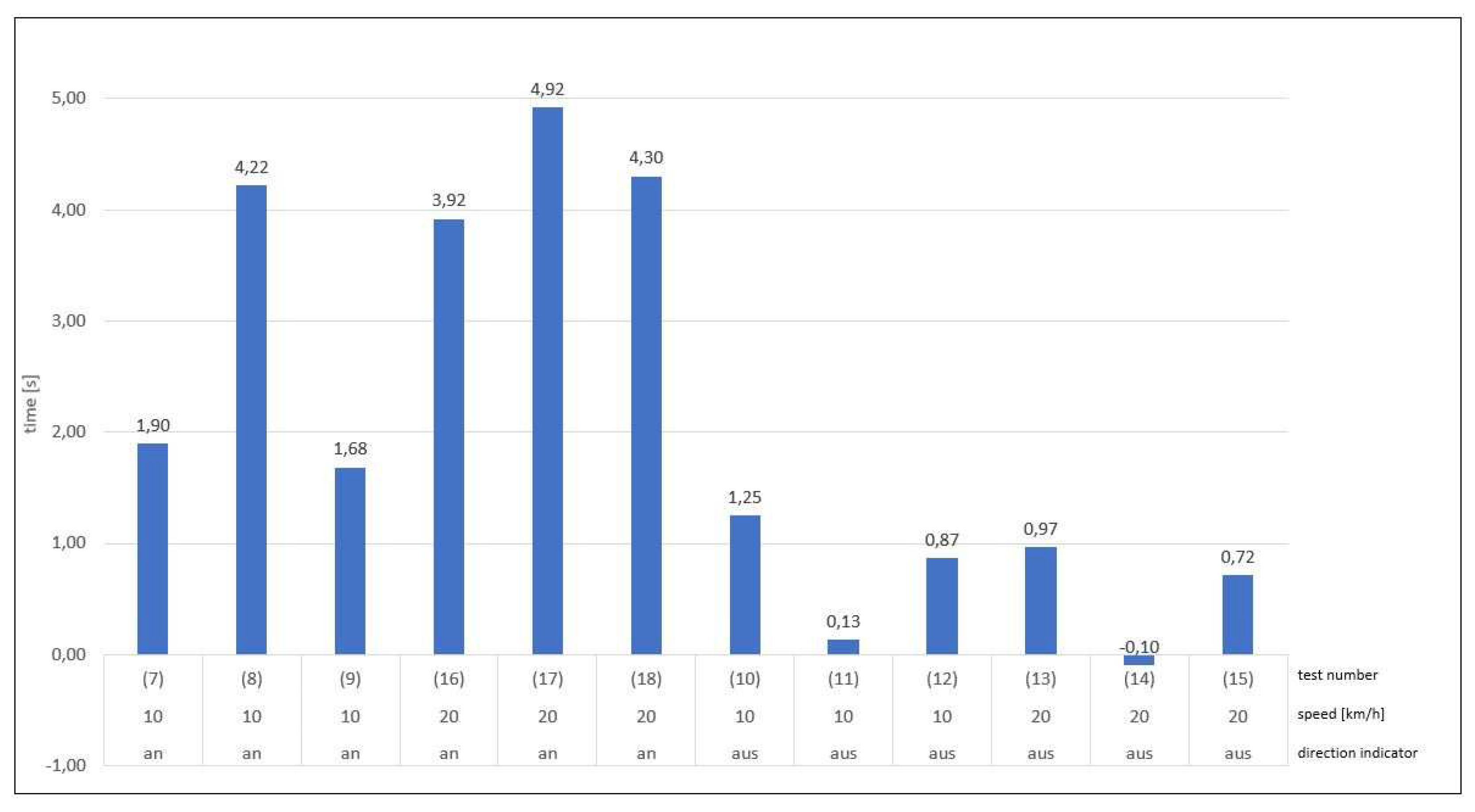
In the dynamic tests with a simulated turning process of the freight vehicle and a resulting crossing with the movement path of the VRU, the temporal response of information and warning signals to the vehicle driver was evaluated in particular. In this setup, only the Mercedes test vehicle was tested in twelve runs. It was found that if the turn signal was not engaged, the information signal was triggered first. If, on the other hand, the turn signal was activated, the warning signal was triggered directly in four out of seven cases and not the information signal first. Since the driver could not notice the visual signal if he did not look toward the A-pillar or into the instrument cluster at the moment of triggering, the following observations were based on the acoustic warning signal, which can be perceived regardless of the direction of gaze. The acoustic signal was triggered on average 0.1 s after the visual signal. First, the time was calculated for each run, which remained after the triggering of the acoustic warning signal until the theoretical collision. As shown in
Figure 7, in cases (7), (8), (9), (16), (17) and (18) the turn signal was engaged on the right. In cases (7) and (9), it can be seen that they had a lower remaining time. In experiment number (7), the turn signal was not activated immediately at the start of the experiment, but only in the course of the approach. In the case of test number (9), the sequence and execution were observed correctly, so that here a delayed detection by the assistance system can be assumed. Furthermore, it is noticeable that in the test runs (10), (11), (12), (13), (14) and (15) without the direction indicator switched on, the remaining time until the theoretical collision is on average more than four times shorter. The negative time indicated in test (14) means that here the warning signal did not occur until after the collision.
For the warning signal, these tests show a clear dependence on the activity state of the right-hand direction indicator. By activating it, the driver announces his intention to turn not only to the surroundings but also to the assistance system, so that the warning signal is triggered significantly earlier.
Figure 8.
Remaining time between the occurrence of the acoustic warning signal and the theoretical collision.
Figure 8.
Remaining time between the occurrence of the acoustic warning signal and the theoretical collision.
During the tests, as well as during the overhaul runs in public road traffic, it was found several times that the radar-based system of the Mercedes test vehicle triggered an information signal due to VRUs crossing behind the vehicle.
3.5. Integration of blind spot assistance systems into the avoidability analysis
In cases where the VRU has been detected, the driver has been warned, and an accident still occurs, the question arises as to whether this leads to a significant change in the driver's reaction consideration during the technical avoidability analysis.
In the following, our results used as examples to show how a blind spot assistance system can be integrated into the technical avoidability analysis. The definition of an objective reaction prompt point for the commercial vehicle driver is difficult in the accident scenario since the VRU for the driver is only temporarily recognizable in the different exterior mirrors during the pre-collision-phase. Due to the various critical areas to be observed during a right-turn maneuver with a heavy commercial vehicle in a confined urban environment, it is impossible to understand the driver's gaze beyond doubt. Accordingly, no objective request for reaction can be determined. In the presence of a blind spot assistance system, on the other hand, the acoustic warning signal can be used as the latest possible reaction prompt point. In contrast to the purely visual information signal, this is perceptible to the driver regardless of the driver's gaze.
The dynamic turning tests result in a considerable difference in the triggering times for the warning message depending on the driver's timely actuation of the right-hand direction indicator during the pre-collision-phase. If the direction indicator was activated early, the warning signal was triggered 3.9 s to 4.9 s before the calculated theoretical collision point during four test runs. In one case, the acoustic warning was issued 1.9 seconds before the collision, as the direction indicator was activated late. In a test run with the direction indicator activated, the acoustic warning was triggered 1.7 seconds before the point of a collision without any obvious cause.
Figure 9.
Shutter release range of the blind spot assistance system when the direction indicator is activated.
Figure 9.
Shutter release range of the blind spot assistance system when the direction indicator is activated.
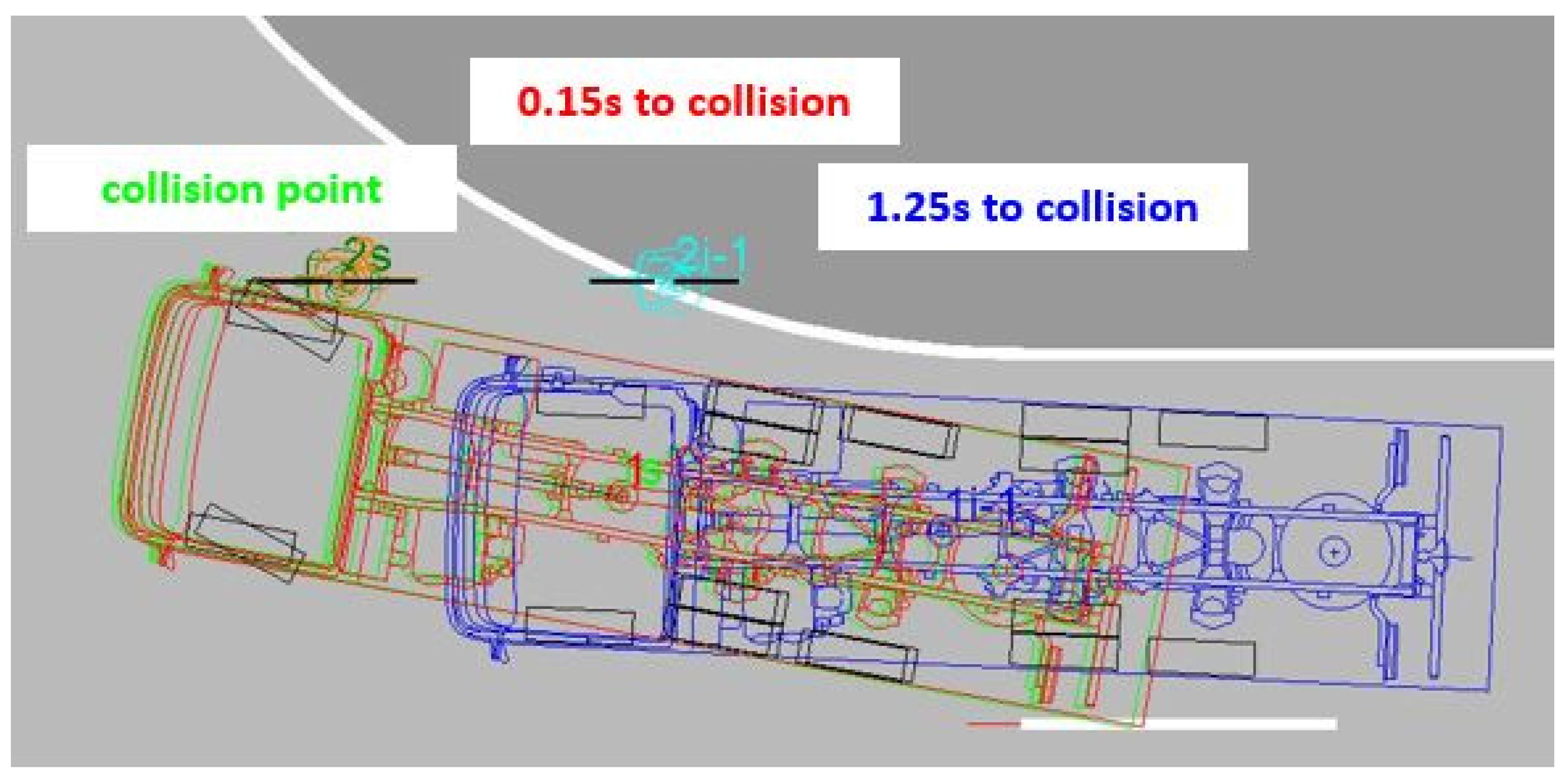
Without actuating the direction indicator, the blind spot assistance system is activated by the steering angle to the right, resulting in significantly later response times. In five test runs, the acoustic warning signal was triggered 0.15 s to 1.25 s before the calculated collision point. In one test, the warning appeared at 0.1 s after the collision.
Figure 10.
Blind spot assistance system triggering range without direction indicator activated.
Figure 10.
Blind spot assistance system triggering range without direction indicator activated.
The subsequent reaction time of the driver between the occurrence of the warning signal and the initiation of a defensive reaction in the form of a braking maneuver is highly dependent on the characteristics and abilities of the driver. It is subject to a corresponding range of fluctuation. In UN-ECE R151, a driver response time of 1.4 s is used to define the performance criteria of the blind spot assistance systems [
5] and should, therefore, also be used in the present calculations. With the emergency braking deceleration of up to 7.36 m/s² measured in braking tests with the test vehicles, a braking time of 0.57 s can be calculated for a maximum permissible turning speed of 15 km/h.
Thus, it can be concluded from the tests that without activation of the right-hand direction indicator, the acoustic warning message of the blind spot assistance system occurred too late in all tests carried out for the driver to have been able to initiate a braking reaction at all if a reaction time had been considered before the collision with the VRU.
When the direction indicator is activated, the acoustic warning is issued so that, in four out of six cases, a time window of 2.5 s to 3.5 s remained after the reaction time had elapsed to bring the vehicle to a standstill. In the two test runs with the delayed response of the acoustic warning, the available braking time was 0.3 s to 0.4 s. During this period, it would not have been possible to bring the vehicle to a complete standstill but to slow it down considerably, thereby significantly reducing the severity of the accident and, thus, the consequences of the accident.
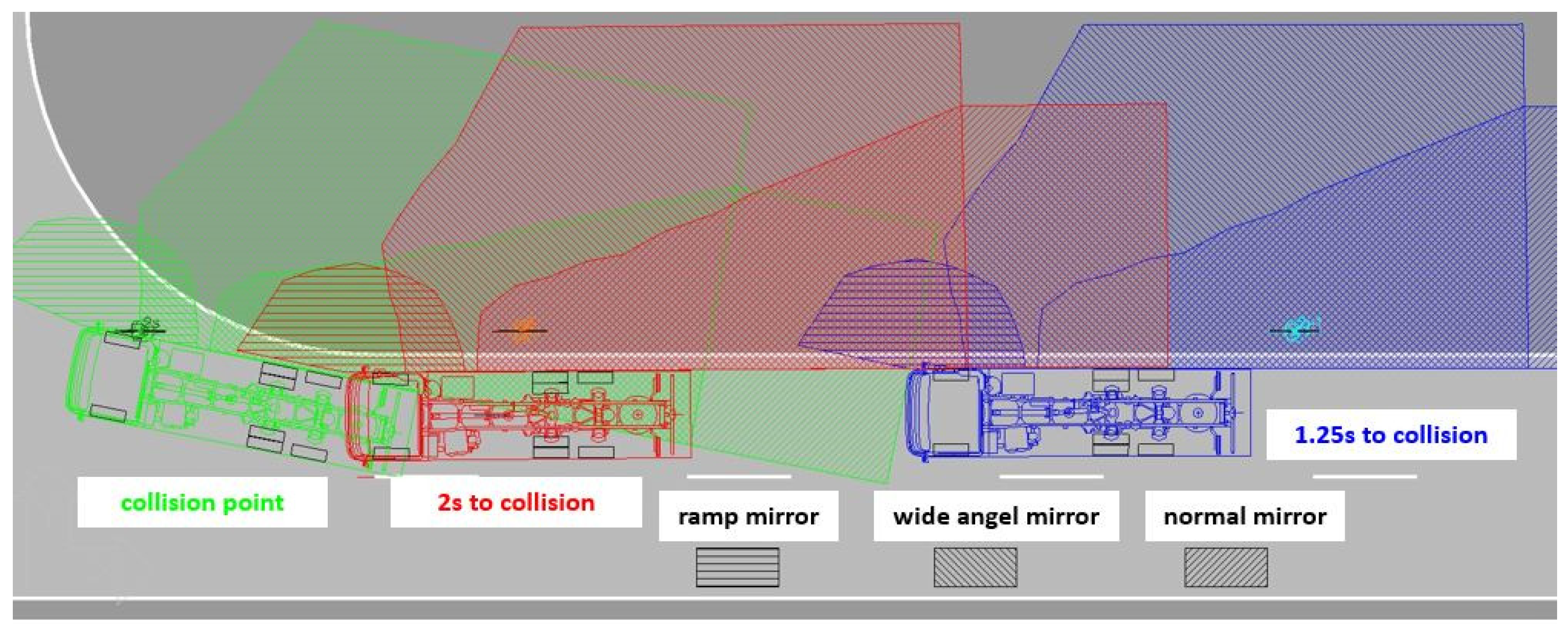
Figure 11 shows the reconstruction result of the same traffic accident constellation without considering a blind spot assistance system. Here, it is investigated when the VRU would be recognizable to the commercial vehicle driver in the reconstructed approach constellation in which indirect fields of view via exterior mirrors or camera systems. The area visible in the exterior mirrors of the Mercedes test vehicle to the right of the vehicle was measured and drawn into a scaled plan view.
Figure 11 shows that the VRU is typically perceptible in at least one indirect field of view over several seconds before the collision.
Accordingly, the accident would always be avoidable for the commercial vehicle driver when looking into the respective exterior mirror or the respective monitor at the right time. Since, as described, the driver's gaze could be more comprehensible, from a purely technical point of view, neither an objective reaction prompt point can be defined, nor a meaningful avoidability analysis can be carried out in this accident constellation. According to the current state of the art, only a legal assessment of the avoidability for the commercial vehicle driver can be carried out here, considering the traffic situation.
4. Discussion
Now the knowledge gained has to be integrated in the common practice of the analysis of traffic accidents between turning commercial vehicles and VRUs. First the accident analysis must clarify the course of the accident and the cause of the accident. The blind spot assistance systems investigated here is an exclusively warning function without any active intervention. But although it might be of interest why the assistance system could not avoid the accident. Subsequently, an avoidability investigation must be carried out, also taking into account the blind spot assistance system.
4.1. Factors influencing a turning accident involving a blind spot assistance system
After evaluating the tests carried out and considering the findings from the ADAC test series, the [
1,
10,
19] possible factors influencing the functional reliability of a blind spot assistance system can be systematically determined according to the current state of the art. As part of the reconstruction of a turning accident involving a commercial vehicle equipped with a blind spot assistance system, these possible sources of error must first be fully recorded when the accident is recorded and systematically checked in the subsequent analysis to be able to identify the cause of the accident reliably.
In the first step, the commercial vehicle involved in the accident must be subjected to a technical vehicle inspection, whereby in the event of a turning accident, the focus should be on visibility from the driver's seat and, if installed, on a blind spot assistance system.
The assistance system and its sensor and display components on or in the vehicle must be identified and subjected to a basic functional test. As explained above, basic conclusions can already be drawn from the type and installation of the environmental sensors about the detection range and detection reliability. The type and location of warnings issued to the driver determine the extent to which they can later be used as response prompt signals. In hardly any of the blind spot assistance systems examined, internal monitoring of functionality is carried out, and accordingly, no error message is sent to the driver in the event of a malfunction. An inspection of the assistance systems is still not part of the periodic technical inspection [
23,
24]. However, even if this were the case, a malfunction or total failure of the system due to an internal fault or, for example, sensor contamination that occurred immediately before the collision could not be ruled out. This also applies to possible system manipulation.
Like the fields of view of the mirror systems, the coverage area of the environment sensors should also be determined and measured. The results of the ADAC tests [
1,
10,
19] showed that the activation of the blind spot assistance system, the coverage area size, or the activation of a supplementary camera monitor system is often linked to certain speed ranges with a very widespread. As we saw in our static tests especially in a camera-based system the detection range is not as wide as the area that can be seen in the camera-monitor-system and in longitudinal and lateral direction even smaller than the range of a radar-based system. Depending on the situation at the accident site there might be a great difference in the function of the assistance system according to the type of sensor that is used in the accident vehicle.
The ADAC found [
1,
10,
19] that for systems with ultrasonic-based environment sensors, it can be assumed that any object on the right-hand side of the road will permanently trigger the blind spot assistance system, since the ultrasonic system cannot differentiate between static objects and VRU. The evaluation algorithms of camera-based systems can distinguish VRU from static objects with high reliability so that hardly any false alarms are induced. In many systems, the classification of VRU and the suppression of false triggering are based on the difference in speed to the commercial vehicle. In many cases, therefore, at a similar speed and a lower speed of the VRU compared to the commercial vehicle, no warning message is sent to the driver. A reliable warning is only triggered if the VRU overtakes the commercial vehicle from behind with higher speed as our dynamic parallel driving tests show. In the case of radar systems, the detection range is highly dependent on the installation position of the vehicle. It is impossible to distinguish between static and dynamic objects with sufficient reliability in all systems as the ADAC found [
1,
10,
19]. At the same time, radar-based systems can detect occasional false triggering by objects moving behind the vehicle at the edge of the detection area because of the wide detection range of this type of sensor.
As shown in the dynamic turning tests, the response of the blind spot assistance system is significantly dependent on the actuation state of the right-hand direction indicator. Clarifying this state of activity on the commercial vehicle involved in the accident is only possible through police witness interviews. In the future, it would be desirable if an event data recorder, which has yet to be introduced for heavy commercial vehicles, would also record and store the activity states of the lighting devices on the vehicle.
The warnings to the driver must be determined whether they are emitted exclusively visually or acoustically in the event of an acute risk of collision In accident analysis, only an acoustic warning signal that is independent of the instantaneous direction of gaze can be used as an objective reaction prompt because it is not possible to find out where the driver was looking at the moment the warning was given .
The coverage area of the environment sensors determined in the vehicle inspection must be compared with the lateral distance between the movement corridors of the commercial vehicle and the VRU, which results from the course of road and the cycle path or footpath at the accident site. If the VRU is temporarily or constantly at the limit of the system’s specific detection range, it cannot be assumed that the blind spot assistance system will respond safely. Especially for camera-based systems this lateral range is quite small.
If, during the pre-collision-phase, there is a temporary or permanent obstruction of sight due to an obstacle between the vehicle and the VRU, this cannot be detected by the blind spot assistance system, and no warning message can be issued. Neither the systems tested by the ADAC nor the systems in our own experiments could at any time detect a VRU behind an obstacle. When assessing possible obstacles, attention must be paid to the position of the environment sensors on commercial vehicle.
4.2. Integration of blind spot assistance systems into the avoidability analysis
To be able to understand the interaction between the warning blind spot assistance system and the driver during a turning accident, tests must be carried out, taking into account the relevant external and internal factors. In addition to the accident recording according to the current state of the art, the performance data of the blind spot assistance system must also be collected as described above. The course of the accident reconstructed based on these connecting facts with unavoidable tolerance ranges can then be reconstructed, whereby the determined upper and lower limits of the tolerance ranges must be examined in more detail using experiments. As a rule, the VRU will have been seriously or fatally injured, so the primary decision must be made as to which limit values are to be applied in favor of the driver of the commercial vehicle involved in the accident.
If the assistance system is found to be functioning correctly, the acoustic warning signal of the assistance system can be understood as an objective request to react, since the driver must initiate braking at the latest in response to this warning of a concrete risk of accident. As described above, the triggering point depends on both the respective system and the environment, so that corresponding tests must be carried out. The activity status of the right-hand direction indicator plays a significant role here.
Depending on the remaining time between the occurrence of the warning signal and the theoretical collision point, the assistance system can have a positive or negative effect for the driver in the avoidability consideration. If the warning occurs in time, as in our experiments, the assistance system provides a clear avoidability of the accident for the driver of the commercial vehicle. However, in the case of larger distances between the VRU and the commercial vehicle or visual obscuration, constellations are also possible in which the warning occurs very late or not at all. In this case, the accident may no longer be avoidable for the driver when reacting to the warning signal.
5. Conclusions
The tests carried out showed that the blind spot assistance systems installed in commercial vehicles with an exclusive warning function can help to avoid an inner-city turning accident with a VRU moving in parallel. The technical characteristics of the environmental sensors used, and the accident location limit the reliability of the assistance systems, so they cannot avoid every such accident by far.
From a technical point of view, the audible warning message of a blind spot assistance system can be used as an objective reaction prompt point for the commercial vehicle driver in a critical turning situation. The timing of the warning signal depends decisively on whether the driver activated the right-hand direction indicator in good time before the junction in the approach phase. Just with an activated direction indicator the blind spot assistance system is available in its full range of functions and can warn in sufficient timespan prior of an imminent collision with a VRU.
The operating status of the direction indicator will not only play a role in the avoidability analysis for the VRU but will also influence the perceptibility of the VRU by the driver in the avoidability analysis. On the one hand, the direction indicator shows the VRU the commercial vehicle's intention to turn, so that the VRU can initiate an avoidance reaction if necessary. On the other hand, the activation of the direction indicator on the commercial vehicle also contributes to the activation of the blind spot assistance system, which supports the driver in detecting a VRU in good time.
With the investigations and considerations presented here, it is now possible to integrate a blind spot assistance system into the technical-forensic accident reconstruction from cause research to avoidability analysis. After checking the correct function of the assistance system, the triggering time of the warning message can be determined under the respective circumstances of the accident, thus defining an objective reaction request point for the driver of the commercial vehicle. In this way it will be easier to decide from a technical point of view whether a turning accident would have been avoidable for the driver or not.
For the moment, the legal assessment of the influence of the blind spot assistance system on the course of the accident and the avoidability analysis for the commercial vehicle driver remains unclear. Presently, assistance systems are considered pure support so that the responsibility for driving behavior and, thus, an accident always remains with the driver without restriction. From a legal point of view, the avoidability study usually needs to consider the potential and the correct functioning of assistance systems installed in the vehicle. From the authors' point of view, the assistance systems examined here, and other assistance systems have the potential to significantly influence the course and avoidability of an accident so significantly that a more differentiated legal view would be appropriate here. Suppose the influence of the assistance system can be reconstructed with sufficient certainty. In that case, it is still possible to offer a much more far-reaching, objectively comprehensible decision-making aid through technical reconnaissance than was previously the case in the accident constellation under consideration.
Furthermore, even with a precise reconstruction of the course of the accident and correspondingly detailed and reproducible tests about the triggering times of the blind spot assistance system, a tolerance range remains that could only be further reduced by the introduction of an Event Data Recorder (EDR) for heavy commercial vehicles. In addition to driving data, this EDR should also contain information on warning and active interventions by driver assistance systems to be able to understand the influences of these systems reliably.
