
Submitted:
08 November 2023
Posted:
09 November 2023
You are already at the latest version
Abstract
Milling machines have made denture fabrication possible with high accuracy in a short time. However, the relationship between the milling conditions, accuracy, and milling duration has not been clarified. This study aimed to clarify the effects of milling conditions on surface roughness and milling duration. The specimen was designed using a CAD software, and milled using PMMA disks. In milling, the parameters of finishing the specimen surface were adjusted. Three different spindle speeds and four different feed rates were set. Twelve combinations of each parameter were used for milling, and the surface roughness and milling duration were measured. Results showed that the surface roughness significantly increased with the feed rate on the slopes of the specimen. The surface roughness differed with the spindle speed on the left and right slopes. The spindle speed and feed rate did not affect the surface roughness on the flat surface. The milling duration was not affected by spindle speed but decreased as the feed rate increased. In conclusion, by increasing both the spindle speed and feed rate, the milling duration could be shortened while maintaining a constant surface quality. The optimum milling conditions were a spindle speed of 40,000 rpm and feed rate of 3,500 mm/min.
Keywords:
CAD/CAM
; milled denture
; surface roughness
; spindle speed
; feed rate
; fabrication time
1. Introduction
Computer-aided design/computer-aided manufacturing (CAD/CAM) has shown remarkable progress in recent years, and its application in dentistry is advancing annually [1]. There has been an expanding application of digital complete dentures [2,3]. New fabrication methods, including milling complete dentures using custom disks and prefabricated artificial teeth, have been developed [4] and their vast clinical applications in university hospitals have been reported [5]. Digital complete dentures can be fabricated using two methods: subtractive manufacturing using a milling machine or additive manufacturing using a 3D printer. In milling, a prefabricated polymethyl methacrylate (PMMA) disk that has been pre-polymerized under ideal conditions is milled to a denture shape, which allows excellent mechanical properties [6,7]. Iwaki et al. showed that PMMA blocks had higher flexural strength and modulus, as well as lower water sorption and discoloration, than blocks fabricated using conventional denture base resins [6]. Similarly, Hada et al. reported that prefabricated PMMA disks had superior flexural strength compared with self-polymerizing resin and heat-polymerizing resin [7]. Moreover, a prefabricated PMMA disk is not affected by polymerization shrinkage, Goodacre et al. reported that it was most accurate and reproducible when compared with conventional methods such as pack and press, pour, and injection [8]. Murali et al. examined changes in surface properties using artificial saliva and found that prefabricated disks were as clinically acceptable as conventional resins [9]. In addition, the fabrication of a single milled denture base and artificial teeth requires approximately 2 h individually for fabrication [10]; however, milled complete dentures can be fabricated in a lesser duration than dentures fabricated using the conventional method. Otake et al. reported that comparing the cost-effectiveness of milled complete dentures and conventional complete dentures found that the cost of milled dentures was comparatively lower [5]. This could be attributed to the reduced labor cost of denture fabrication. Taken together, the use of digital technology to fabricate dentures can reduce the time spent by dental technicians on manual labor and allow more efficient denture fabrication.
The application of digital technology for denture fabrication has many advantages compared with conventional methods. However, polishing, which is an important step in the final processing of dentures, has not been digitized and is performed manually by dental technicians. Conventional denture fabrication requires complex work, including modification of the denture form after it has been retrieved from gypsum and finishing and polishing. Previous studies examining the surface quality of complete dentures have shown that milled complete dentures have better surface quality than conventional or 3D-printed complete dentures [11,12,13,14]. In addition, ideally, milled complete dentures should require minimal time for fabrication and have good surface quality. However, the optimal milling conditions for achieving these parameters remain unclear.
The surface roughness of a composite resin block improves the bonding strength and is influenced by the milling conditions [15]. A previous study measured the milling duration; however, it did not discuss the relationship between the milling duration and the milling conditions. Another study showed that changing the milling conditions affects the quality and accuracy of materials; moreover, surface roughness is widely used as an index for evaluating machining accuracy [16,17,18]. Tseng et al. suggested that the milling speed is the most significant factor affecting surface roughness and that optimum surface roughness can be obtained by reducing the feed rate and increasing the spindle speed when the hardness of the material is high [16]. Ribeiro et al. showed that, in addition to speed, the depth of the cut in the radial direction as well as the interaction between the radial and axial depths of the cut affect surface roughness; furthermore, the smaller the depth of the cut, the better the surface roughness [17]. Similarly, Nurhaniza et al. found that a combination of high milling speed, low feed rate, and small depth of cut comprised the optimal conditions for minimal adequate surface roughness [18]. Although milled dentures ideally have a high accuracy, parameters such as the type of milling tool, rotation speed, and feed rate during milling can affect the actual surface roughness of the material [19]. Rough milling is possible using a large-diameter tool and fine milling with a narrow-diameter tool. Similarly, for milled denture fabrication, tools with a larger diameter allow for faster fabrication; however, the surface becomes rougher and requires more polishing after fabrication. In contrast, tools with a narrower diameter allow more precise milling of surfaces and less polishing; however, there is an increase in the milling duration as well as the wear and tear of tools [20]. No studies have evaluated the effects of milling tools and conditions on machining accuracy and the time required for denture base fabrication using PMMA disks; further, the optimal milling conditions for the fabrication of milled dentures remain unclear.
Therefore, the objective of this study was to determine the effects of different milling conditions on the surface properties and milling duration of PMMA disks for denture base fabrication using a milling machine. The null hypothesis was that the surface roughness and milling duration would not differ under different milling conditions.
2. Materials and Methods
2.1. Design of the specimen
First, a general-purpose CAD software (Fusion360; Autodesk Inc., San Rafael, CA, USA) was used to design a model for milling to imitate a maxillary complete denture (Figure 1). The left and right parts simulated the jaw ridge, and the flat part in the center simulated the palatal area. This design was exported in Standard Tessellation Language format.
2.2. Data for milling
The Numerical Control (NC) data that could be milled on a dental milling machine (MD-500; Canon Electronics Inc., Saitama, Japan) were created using a dental CAM software (hyperDENT V9; FOLLOW-ME! Technology Group, Munich, Germany) (Figure 2). Three specimens were evenly placed on one disk, with each specimen having a total of eight supports. Subsequently, three specimens were milled from a single PMMA disk (Ivotion Base PinkV, Ivoclar Vivadent, Schaan, Liechtenstein).
2.3. Milling the specimens
The cutting paths for the specimens were output and the specimens were milled. Milling was performed using three types of tools: 6-mm diameter square end mill (AE-TS-N 6×18; OSG CORPORATION, Aichi, Japan), 3-mm diameter square end mill (AE-TL-N 3×15; OSG CORPORATION, Aichi, Japan), and 2-mm diameter ball end mill (WXL-LN-EBD R1×20×4; OSG CORPORATION, Aichi, Japan). The milling was performed in the order listed in Table 1 as following: roughing using the 6-mm diameter tool, medium roughing using the 3-mm diameter tool, medium roughing using the 2-mm diameter tool, and finishing using the 2-mm diameter tool. To evaluate the surface roughness of specimens used in this study, we adjusted parameters during the finishing stage using the 2-mm diameter tool that affect the surface properties. Specifically, we set three different spindle speeds (20,000, 30,000, and 40,000 rpm) and four different feed rates (2,000, 2,500, 3,000, and 3,500 mm/min) for the finishing stage; accordingly, 12 combinations were created and we examined the accuracy of the specimen and milling duration with each combination. Two PMMA disks were used for each combination of spindle speed and feed rate; accordingly, six specimens were milled for each combination (Figure 3). Each of the three types of tools was replaced for each combination in order to ensure that the wear and tear of the tool, as well as other factors, would not affect the milling conditions. The milled specimens were separated from the disk to allow distinction between the left and right sides. The sample size was calculated using an analysis software program (G*Power 3.1.9.7; Kiel University, Kiel, Germany). Based on a previous study [15], the sample size required to investigate the accuracy and milling duration for one combination of spindle speed and feed rate was determined to be 6.
2.4. Evaluation of surface roughness
The surface roughness was measured as an index for evaluating the milling accuracy. Specifically, the surface roughness of the specimens was measured using a compact surface roughness measuring machine (SURFTEST SJ-210; Mitutoyo, Kanagawa, Japan). The measurement conditions are listed in Table 2. Three points were measured on each specimen, i.e., the right slope, left slope, and central flat surface (Figure 4). While measuring points on the right and left slopes (Figure 4a and Figure 4b), the specimen was fixed and set such that the measuring instrument was aligned perpendicularly to the measurement surface. Measurements were performed thrice at each location, with the triplicate measurement values being averaged to minimize measurement error. All measurements were performed by the same investigator to avoid measurement errors.
2.5. Measurement of milling duration
The milling duration was recorded on the MD-500 operating application (md-gear; Canon Electronics Inc., Saitama, Japan). The milling duration per specimen was averaged to avoid the effect of specimen placement and wear and tear of the tools on the milling conditions.
2.6. Statistical analysis
The data regarding surface roughness and milling duration were analyzed using a software program for statistical analysis (IBM SPSS Statistics V28; IBM Corp., Armonk, NY, USA). The statistical significance of the results was determined using the Kruskal-Wallis test and Dunn's multiple comparison test.
3. Results
3.1. Surface roughness
The results of surface roughness measurements on the left slope of the specimen are listed in Table 3. Comparison of the effects of different feed rates at the same spindle speed on the left slope of the specimen (Figure 4-a) revealed that the surface roughness significantly differed between feed rates of 2,000 mm/min and 3,500 mm/min at a spindle speed of 20,000 rpm (p = 0.002), between feed rates of 2,000 mm/min and 2,500 mm/min at a spindle speed of 30,000 rpm (p = 0.04), between feed rates of 2,000 mm/min and 3,000 mm/min at a spindle speed of 30,000 rpm (p = 0.006), and between feed rates of 2,000 mm/min and 3,500 mm/min at a spindle speed of 30,000 rpm (p < 0.001). However, a comparison of the effects of different spindle speeds at the same feed rate revealed that surface roughness significantly differed between spindle speeds of 20,000 and 40,000 rpm at a feed rate of 2,000 mm/min (p = 0.04). Although there were no significant differences in surface roughness at feed rates of 2,500 mm/min, 3,000 mm/min, and 3,500 mm/min, the surface roughness tended to increase with the spindle speed.
The results of surface roughness measurements on the right slope of the specimen (Figure 4-b) are listed in Table 4. Surface roughness did not significantly differ among different feed rates at the same spindle speed. Further, a comparison of the surface roughness at the same feed rate but different spindle speeds revealed that it significantly differed between spindle speeds of 20,000 rpm and 30,000 rpm at a feed rate of 2,000 mm/min (p = 0.05), spindle speeds of 20,000 rpm and 40,000 rpm at a feed rate of 2,000 mm/min (p = 0.001), spindle speeds of 20,000 rpm and 40,000 rpm at a feed rate of 2,500 mm/min (p < 0.001), spindle speeds of 30,000 rpm and 40,000 rpm at a feed rate of 2,500 mm/min (p = 0.001), spindle speeds of 20,000 rpm and 30,000 rpm at a feed rate of 3,000 mm/min (p = 0.01), spindle speeds of 20,000 rpm and 40,000 rpm at a feed rate of 3,000 mm/min (p < 0.001), spindle speeds of 20,000 rpm and 30,000 rpm at a feed rate of 3,500 mm/min (p = 0.04), and spindle speeds of 20,000 rpm and 40,000 rpm at a feed rate of 3,500 mm/min (p < 0.001). The surface roughness decreased as the spindle speed increased.
3.2. Milling duration
The results of milling duration are listed in Table 6. Comparison of the milling duration at the same spindle speeds revealed that the milling duration significantly differed between feed rates of 2,000 mm/min and 3,000 mm/min at a spindle speed of 20,000 rpm (p = 0.004), feed rates of 2,000 mm/min and 3,500 mm/min at a spindle speed of 20,000 rpm (p < 0.001), and feed rates of 2,500 mm/min and 3,500 mm/min at a spindle speed of 20,000 rpm (p = 0.003). At a spindle speed of 30,000 rpm, the milling duration significantly differed between feed rates of 2,000 mm/min and 3,000 mm/min (p = 0.003), feed rates of 2,000 mm/min and 3,500 mm/min (p < 0.001), and feed rates of 2,500 mm/min and 3,500 mm/min (p = 0.003). In addition, at a spindle speed of 40,000 rpm, the milling duration significantly differed between feed rates of 2, 000 mm/min and 3,000 mm/min (p = 0.002), feed rates of 2,000 mm/min and 3,500 mm/min (p < 0.001), and feed rates of 2,500 mm/min and 3,500 mm/min (p = 0.003). In contrast, milling duration did not significantly differ between different spindle speeds at the same feed rate.
4. Discussion
According to the obtained results, the null hypothesis was rejected, and a significant difference in surface roughness and milling duration was observed under different milling conditions. It was suggested that the milling duration could be reduced by changing the milling conditions while maintaining the surface properties.
In this study, the surface roughness was measured at several points on the specimen; further, we observed a difference in surface roughness at two points on the left and right sides of the specimen. First, on the left slopes, there was a slight trend toward an increase in surface roughness as the feed rate increased with the same spindle speed. At a spindle speed of 20,000 rpm, there was a significant difference in surface roughness between feed rates of 2,000 and 3,500 mm/min; however, at 40,000 rpm, surface roughness did not significantly differ among the feed rates. This suggests that surface roughness is easily affected by feed rate at low spindle speeds. At feed rates above 2,500 mm/min, surface roughness did not significantly differ among different spindle speeds. However, at a feed rate of 2,000 mm/min, the surface roughness was significantly lower at a spindle speed of 20,000 rpm than at a spindle speed of 40,000 rpm. This suggests that milling at lower spindle speeds is more likely to affect surface roughness. Ideally, the milling duration should be shortened while ensuring accuracy. However, surface roughness may increase as the milling conditions are changed to shorten the milling duration.
Second, on the right slopes, the surface roughness tended to increase with an increase in the feed rate between 2,000 mm/min and 3,500 mm/min, which was similar to the left slope. When comparing spindle speeds, a significant decrease in surface roughness was observed as the spindle speed increased. One possible reason for the difference in the surface roughness variation according to spindle speed between the left and right slopes could be attributed to the difference in the processing direction. The present study applied scanning-line milling, which involves milling from the right to the left end of the specimen. Therefore, on the right slope, the tool cuts down the slope, whereas on the left slope, it cuts up the slope. The main milling methods used are scanning-line and contour-line millings [21,22]. In scanning-line milling, the tool is moved in a fixed direction and the specimen is machined by moving the tool up and down along the target shape. In contrast, in contour-milling, the tool is held at the same height and the target shape is milled by changing the height of the tool each time. Both methods are also used for finishing; furthermore, although scanning-line milling is more accurate, contour-milling is also useful depending on the milling conditions. The present study only used scanning-line milling. Therefore, it is necessary to consider differences in milling methods, including changing the milling method for each processing area. This study was performed using a simple specimen in order to facilitate the evaluation of accuracy. Further studies on the processing methods for specimens with complex curved surfaces, including an actual complete denture, are warranted.
The results of this study show a significant reduction in the milling duration between feed rates of 2,000 mm/min and 3,500 mm/min. This suggests that the feed rate affects the milling duration. Additionally, there was no significant difference in the milling duration between feed rates at intervals of 500 mm/min. Therefore, the feed rate should be adjusted at increments of 1,000 mm/min. However, in practice, desktop dental milling machines, including the machine used in this study, do not always operate at the theoretical feed rate given the small workspace and the insufficient number of strokes to output the set feed rate. Therefore, it is necessary to consider an upper limit while setting the feed rate.
This study has some limitations. The first limitation is the setting of the milling conditions. The present study focused on the number of spindles and feed rate to compare the effects of 12 different combinations on accuracy and milling duration. Other various machining conditions such as cutting depth and step-over may affect the accuracy and milling duration. The actual milling process for fabricating complete dentures involves additional steps and various tools. In addition, factors such as shape, material, and coating may affect the accuracy and speed of the machining process. Therefore, it is necessary to investigate other factors related to machining to determine the optimal denture milling conditions. Furthermore, milling machines other than that used in this study are commercially available in the market. Considering the possibility that the results of this study may not reflect the performance of these machines, the evaluation of other dental milling machines is also necessary. Based on the results of this study, future studies are required with the aim of fabricating complete dentures to verify whether milling can be performed within a short duration and with a high accuracy at any step. Additionally, this study was conducted to determine its clinical utility. Further studies are warranted to determine the optimal shape and material of the tool used for milling the PMMA disk for denture base fabrication.
5. Conclusions
The conclusions drawn from this study are as follows:
- Among the milling parameters, increasing the feed rate led to a reduction in the milling duration.
- The combination of a spindle speed of 40,000 rpm and a feed rate of 3,500 mm/min allowed the shortest milling duration with improved surface roughness, i.e., machining accuracy, among the milling conditions assessed in this study.
Author Contributions
Conceptualization, Y.A.; methodology, Y.A.; software, Y.A.; validation, M.I. and Y.K.; formal analysis, Y.A.; investigation, Y.A.; resources, Y.A.; data curation, Y.A.; writing—original draft preparation, Y.A.; writing—review and editing, M.I., Y.K., M.K. and S.M.; visualization, Y.A.; supervision, M.K. and S.M.; project administration, Y.A.; funding acquisition, M.K. and S.M. All authors have read and agreed to the published version of the manuscript.
Funding
This research was funded by CANON ELECTRONICS INC (Saitama, Japan).
Institutional Review Board Statement
No applicable
Informed Consent Statement
No applicable
Data Availability Statement
No applicable
Acknowledgments
The authors gratefully acknowledge the CAD/CAM team and CANON ELECTRONICS INC (Saitama, Japan) for providing support for this study.
Conflicts of Interest
The authors declare no conflict of interest.
References
- Miyazaki, T.; Hotta, Y.; Kunii, J.; Kuriyama, S.; Tamaki, Y. A review of dental CAD/CAM: Current status and future perspectives from 20 years of experience. Dent Mater J 2009, 28, 44–56. [CrossRef]
- Kanazawa, M.; Inokoshi, M.; Minakuchi, S.; Ohbayashi, N. Trial of a CAD/CAM system for fabricating complete dentures. Dent Mater J 2011, 30, 93–96. [CrossRef]
- Goodacre, C.J.; Garbacea, A.; Naylor, W.P.; Daher, T.; Marchack, C.B.; Lowry, J. CAD/CAM fabricated complete dentures: Concepts and clinical methods of obtaining required morphological data. J Prosthet Dent 2012, 107, 34–46. [CrossRef]
- Soeda, Y.; Kanazawa, M.; Arakida, T.; Iwaki, M.; Minakuchi, S. CAD-CAM milled complete dentures with custom disks and prefabricated artificial teeth: A dental technique. J Prosthet Dent 2022, 127, 55–58. [CrossRef]
- Otake, R.; Kanazawa, M.; Iwaki, M.; Soeda, Y.; Hada, T.; Katheng, A.; Komagamine, Y.; Minakuchi, S. Patient-reported outcome and cost-effectiveness analysis of milled and conventionally fabricated complete dentures in a university clinic: A retrospective study. J Prosthet Dent 2022. Online ahead of print 35440364. [CrossRef]
- Iwaki, M.; Kanazawa, M.; Arakida, T.; Minakuchi, S. Mechanical properties of a polymethyl methacrylate block for CAD/CAM dentures. J Oral Sci 2020, 62, 420–422. [CrossRef]
- Hada, T.; Kanazawa, M.; Iwaki, M.; Katheng, A.; Minakuchi, S. Comparison of mechanical properties of PMMA disks for digitally designed dentures. Polymers (Basel) 2021, 13, 1745. [CrossRef]
- Goodacre, B.J.; Goodacre, C.J.; Baba, N.Z.; Kattadiyil, M.T. Comparison of denture base adaptation between CAD-CAM and conventional fabrication techniques. J Prosthet Dent 2016, 116, 249–256. [CrossRef]
- Srinivasan, M.; Cantin, Y.; Mehl, A.; Gjengedal, H.; Müller, F.; Schimmel, M. CAD/CAM milled removable complete dentures: an in vitro evaluation of trueness. Clin Oral Investig 2017, 21, 2007–2019. [CrossRef]
- Lo Russo, L.; Salamini, A. Single-arch digital removable complete denture: A workflow that starts from the intraoral scan. J Prosthet Dent 2018, 120, 20–24. [CrossRef]
- Srinivasan, M.; Gjengedal, H.; Cattani-Lorente, M.; Moussa, M.; Durual, S.; Schimmel, M.; Müller, F. CAD/CAM milled complete removable dental prostheses: An in vitro evaluation of biocompatibility, mechanical properties, and surface roughness. Dent Mater J 2018, 37, 526–533. [CrossRef]
- Steinmassl, O.; Dumfahrt, H.; Grunert, I.; Steinmassl, P.A. Influence of CAD/CAM fabrication on denture surface properties. J Oral Rehabil 2018, 45, 406–413. [CrossRef]
- Kraemer Fernandez, P.; Unkovskiy, A.; Benkendorff, V.; Klink, A.; Spintzyk, S. Surface characteristics of milled and 3D printed denture base materials following polishing and coating: An in-vitro study. Materials (Basel) 2020, 13, 3305. [CrossRef]
- Srinivasan, M.; Kalberer, N.; Kamnoedboon, P.; Mekki, M.; Durual, S.; Özcan, M.; Müller, F. CAD-CAM complete denture resins: An evaluation of biocompatibility, mechanical properties, and surface characteristics. J Dent 2021, 114, 103785. [CrossRef]
- Matsumura, M.; Nozaki, K.; Yanaka, W.; Nemoto, R.; Takita, M.; Yamashita, K.; Matsumura, M.; Miura, H. Optimization of milling condition of composite resin blocks for CAD/CAM to improve surface roughness and flexural strength. Dent Mater J 2020, 39, 1057–1063.
- Tseng, T. L.B.; Kwon, Y.J. Characterization of machining quality attributes based on spindle probe, coordinate measuring machine, and surface roughness data. J Comput Des Eng 2014, 1, 128–139.
- Ribeiro, J.E.; César, M.B.; Lopes, H. Optimization of machining parameters to improve the surface quality. Procedia Struct Integr 2017, 5, 355–362.
- Nurhaniza, M.; Ariffin, M.K.A.M.; Mustapha, F.; Baharudin, B.T.H.T. Analyzing the effect of machining parameters setting to the surface roughness during end milling of CFRP-aluminium composite laminates. Int J Manuf Eng 2016, 2016, 1–9. [CrossRef]
- Benardos, P.G.; Vosniakos, G.C. Predicting surface roughness in machining: A review, Int J Mach Tool Manuf 2003, 43, 833–844. [CrossRef]
- Ozcelik, B.; Bayramoglu, M. The statistical modeling of surface roughness in high-speed flat end milling. Int J Mach Tool Manuf 2006, 46, 1395–1402. [CrossRef]
- Iwabe, H.; Kikuchi, K.; Futakawa, M.; Kazama, Y. Study on cutting mechanism and cutting performance of inclined surface machining with radius end mill -comparison with cutting method of contouring path and scanning path. J Jpn Soc Precis Eng 2015, 81, 655–660. [CrossRef]
- Iwabe, H.; Kikuchi, K.; Shirai, K. Analysis of theoretical roughness of radius end milling (Geometrical analysis in case of contouring and scanning method and experiments). Trans JSME 2015, 81,15–289.
Figure 1.
Designed specimen.
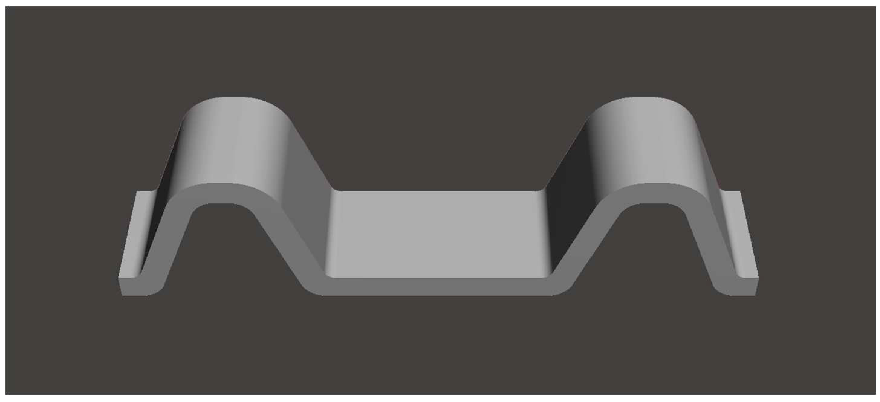
Figure 2.
Locations of the specimens on the CAM software.
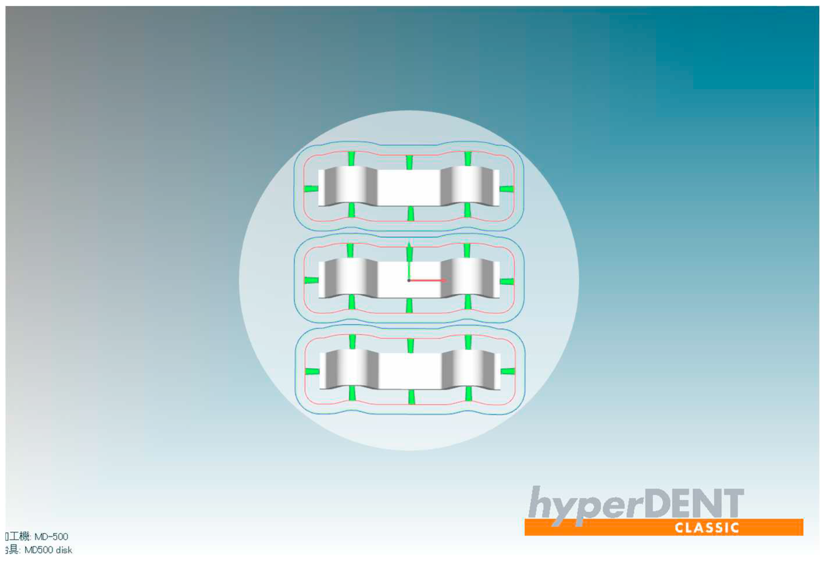
Figure 3.
Specimen immediately after milling.
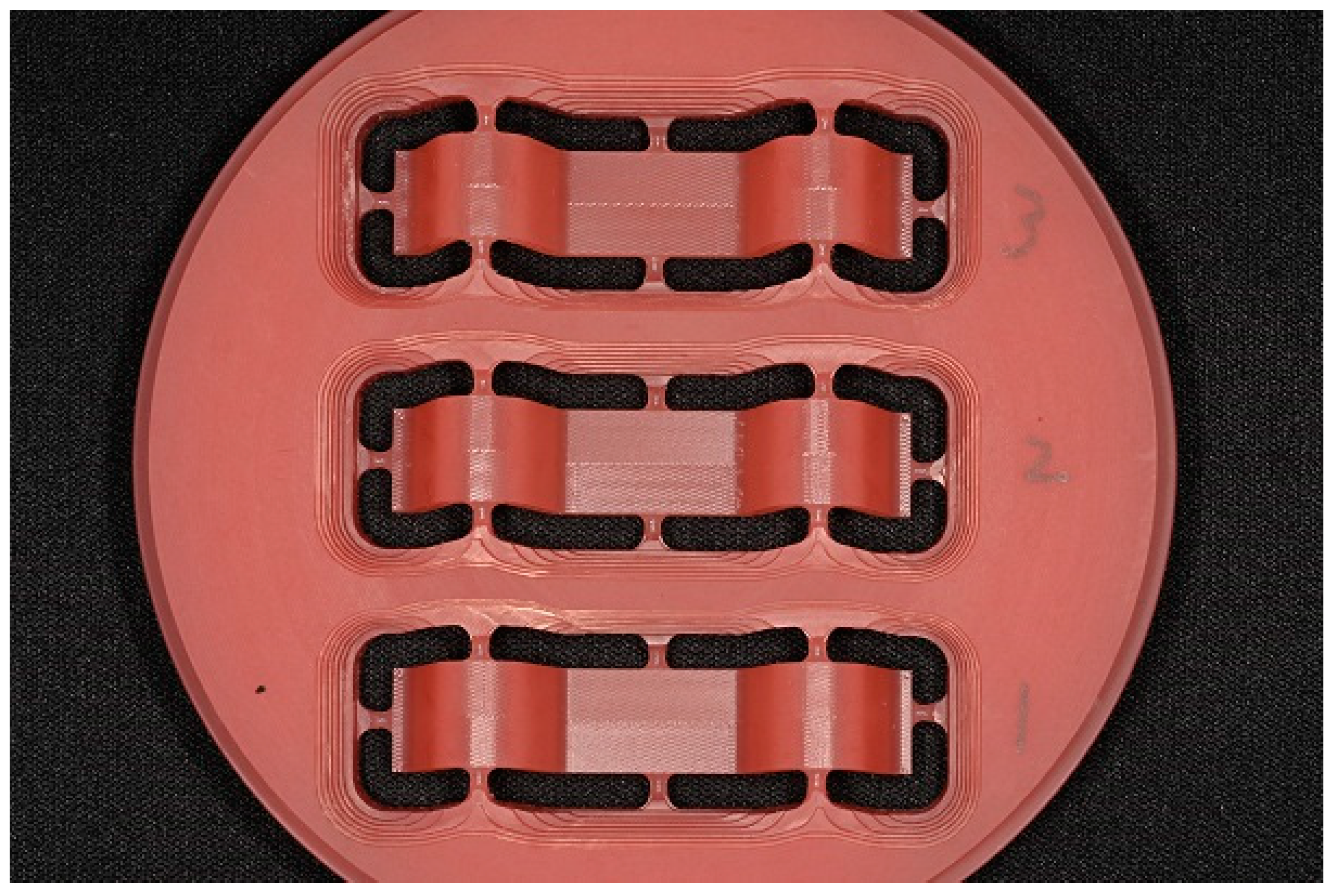
Figure 4.
Locations of surface roughness measurement on the specimen.
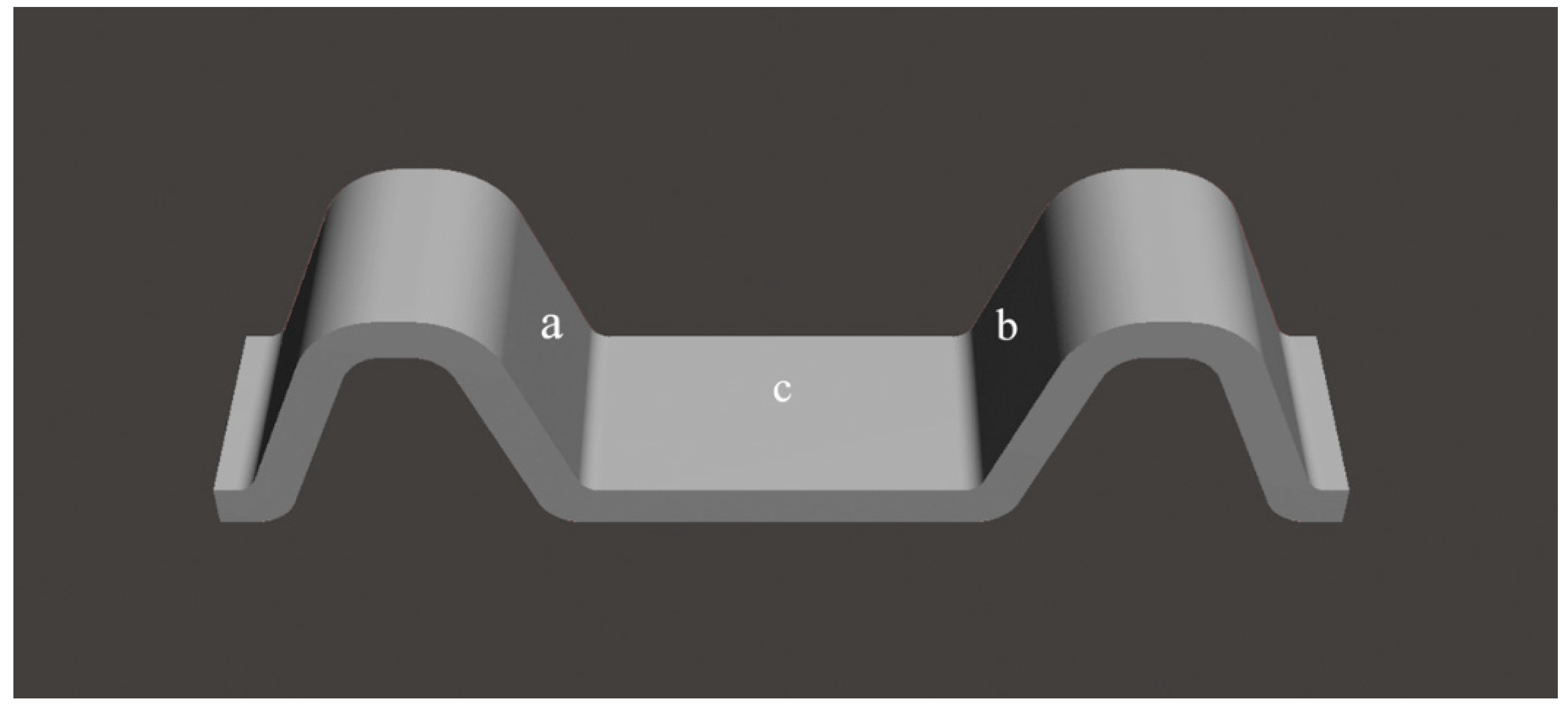

Table 1.
List of tools, spindle speeds, and feed rates.
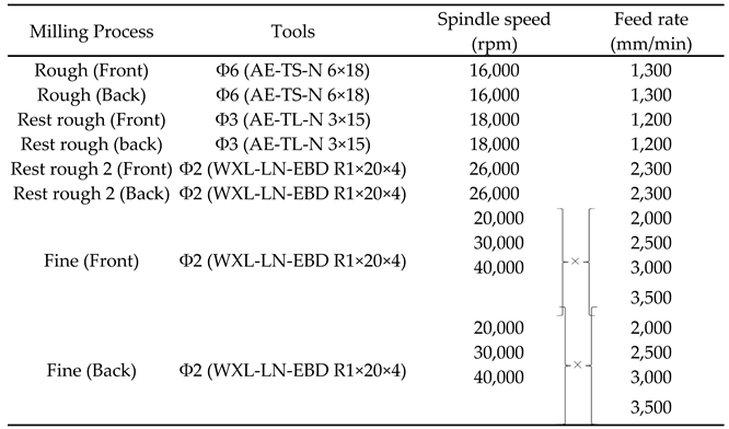 |
Table 2.
Conditions for measuring surface roughness.
| ISO | ISO1997 |
| λc | 2.5 mm |
| λs | 8 μm |
| Length | 6.00 mm |
| Speed | 0.5 mm/s |
Table 3.
Results of surface roughness on the left slope (Figure 4a).
Table 3.
Results of surface roughness on the left slope (Figure 4a).
| Feed rate (mm/min) | Spindle speed (rpm) | |||||
| 20000 | 30000 | 40000 | ||||
| Mean | SD | Mean | SD | Mean | SD | |
| 2000 | 1.62a | 0.16 | 1.72ab | 0.11 | 1.93bcde | 0.28 |
| 2500 | 1.72abc | 0.18 | 2.06cdef | 0.31 | 1.78abcd | 0.12 |
| 3000 | 1.86abcde | 0.07 | 2.12ef | 0.28 | 1.97def | 0.05 |
| 3500 | 2.03ef | 0.11 | 2.28f | 0.21 | 2.04ef | 0.16 |
Statistical results by Kruskal–Wallis test and Dunn's multiple comparison test. Different letters indicate significant differences among the groups (p < 0.05). SD, standard deviation.
Table 4.
Results of surface roughness on the right slope (Figure 4b).
Table 4.
Results of surface roughness on the right slope (Figure 4b).
| Feed rate (mm/min) | Spindle speed (rpm) | |||||
| 20000 | 30000 | 40000 | ||||
| Mean | SD | Mean | SD | Mean | SD | |
| 2000 | 3.55de | 0.43 | 2.39abc | 0.46 | 1.66ab | 0.14 |
| 2500 | 3.74de | 0.25 | 2.87cd | 0.37 | 1.59a | 0.12 |
| 3000 | 4.29e | 0.36 | 2.76abcd | 0.33 | 1.62a | 0.12 |
| 3500 | 4.25e | 0.29 | 2.98cd | 0.31 | 1.96abc | 0.68 |
Statistical results by Kruskal-Wallis test and Dunn's multiple comparison test. Different letters indicate significant differences among the groups (p < 0.05). SD, standard deviation
Table 5.
Results of surface roughness on the central flat surface (Figure 4c).
Table 5.
Results of surface roughness on the central flat surface (Figure 4c).
| Feed rate (mm/min) | Spindle speed (rpm) | |||||
| 20000 | 30000 | 40000 | ||||
| Mean | SD | Mean | SD | Mean | SD | |
| 2000 | 1.53 | 0.05 | 1.44 | 0.06 | 1.42 | 0.03 |
| 2500 | 1.49 | 0.11 | 1.53 | 0.06 | 1.44 | 0.12 |
| 3000 | 1.43 | 0.08 | 1.49 | 0.10 | 1.51 | 0.05 |
| 3500 | 1.51 | 0.05 | 1.41 | 0.11 | 1.46 | 0.05 |
Statistical results by Kruskal–Wallis test and Dunn's multiple comparison test. SD, standard deviation.
Table 6.
Milling duration.
| Feed rate (mm/min) | Spindle speed (rpm) | |||||
| 20000 | 30000 | 40000 | ||||
| Mean | SD | Mean | SD | Mean | SD | |
| 2000 | 35’54” c | 6.16 | 35’54” c | 5.98 | 35’55” c | 5.84 |
| 2500 | 34’35” bc | 5.59 | 34’36” bc | 5.73 | 34’37” bc | 7.23 |
| 3000 | 33’49” ab | 5.53 | 33’49” ab | 4.99 | 33’47” a | 5.38 |
| 3500 | 33’27” a | 5.49 | 33’28” a | 4.52 | 33’28” a | 5.18 |
Statistical results by Kruskal–Wallis test and Dunn's multiple comparison test. Different letters indicate significant differences among groups (p < 0.05). SD, standard deviation.
Disclaimer/Publisher’s Note: The statements, opinions and data contained in all publications are solely those of the individual author(s) and contributor(s) and not of MDPI and/or the editor(s). MDPI and/or the editor(s) disclaim responsibility for any injury to people or property resulting from any ideas, methods, instructions or products referred to in the content. |
© 2023 by the authors. Licensee MDPI, Basel, Switzerland. This article is an open access article distributed under the terms and conditions of the Creative Commons Attribution (CC BY) license (http://creativecommons.org/licenses/by/4.0/).
Copyright: This open access article is published under a Creative Commons CC BY 4.0 license, which permit the free download, distribution, and reuse, provided that the author and preprint are cited in any reuse.


