
Submitted:
01 November 2023
Posted:
03 November 2023
You are already at the latest version
Abstract
In air-breathing proton exchange membrane fuel cells (Air PEM FCs), high rate of water evaporation from the cathode might influence the resistance of the membrane electrode assembly (MEA), which is highly dependent on the water content of the Nafion membrane. We propose a dead-end hydrogen anode as a means of intermediate storage of water/humidity for self-humidification of the membrane. Such inflatable bag integrated with the PEM FC has a potential in blimp applications for anode self-humidification. A dynamic numerical water balance model, validated by experimental measurements, is derived to predict the effect of MEA configuration, membrane’s hydration state, and water transfer rate at the anode on MEA resistance and performance. The experimental setup included humidity measurements, polarization and electrochemical impedance spectroscopy tests to quantify the effect of membrane hydration on its resistance in a lightweight MEA integrated with an inflatable dead-end hydrogen storage bag. Varying current density (20 mA, 40 mA and 60 mA) and cathode humidity (20, 50 and 80%) were examined and compared with the numerical results. The validated model predicts that the hydration state of the membrane and water transfer rate at the anode can be increased by using a thin membrane and thicker gas diffusion layer.
Keywords:
hydrogen fuel cell
; proton exchange membrane
; humidity
; water content
; inflatable hydrogen storage system
; anode self-humidification
; water storage
1. Introduction
Hydrogen-based air-breathing proton-exchange membrane fuel cells (Air PEM FC) mostly use NafionTM membranes, which is a perfluorosulfonic acid (PFSA) membrane with perfluorinated backbones and sulfonic acid as the terminal group. The membrane conductivity properties are strongly affected by its humidification, i.e., the water content of the membrane which is defined by the amount of water absorbed on the sulfonic sites [1,2]. A major disadvantage of Air PEM FC is that the water evaporation from the cathode to the ambient atmosphere is high, thereby influencing the resistance of the Nafion membrane and leading to unstable power output [3,4,5,6,7]. Therefore, sufficient humidity of the membrane must be maintained during the fuel cell operation to improve the power output and prolong its service life. Several humidification methods have been suggested and can be categorized into internal humidification [8] external humidification [9] and self-humidification [10,11]. Internal method such as water stored in cathode end plate and external techniques such as bubble humidifier are more effective but require heavier and more complex monitoring and control subcomponents. Water injection to electrodes in direct or indirect modes has improved fuel cell performance [12,13]. Self-humidification methods such as adding the hydrophilic nano particles to the membrane [14,15,16] or catalyst layer [17,18,19,20] and using double gas diffusion layer [10] have been effective for low-power applications but is also significantly influenced by the operating conditions. In a worst-case scenario, when the Air PEM FC is required to operate in a dry condition, the self-humidification method must rely solely on water produced electrochemically at the cathode. Therefore, understanding the transport of water produced at the cathode across the membrane electrode assembly (MEA) during the FC operation is essential for developing suitable water management strategies in such cases.
In an FC, current flow is associated with the drag of water molecules from the anode to the cathode side, a phenomenon known as electro-osmotic drag (EOD) transport, which depends on the water content of the membrane [21]. These dragged water molecules, combined with water produced at the cathode and accumulate on the cathode side of the membrane. This accumulation creates a water content gradient within the membrane, leading to the back-diffusion of water molecules in the opposite direction [22]. Net transport of water across the membrane is influenced by the water concentration at electrodes and other factors such as temperature, pressure, membrane water content, membrane thickness, gas diffusion layer (GDL), and the humidity of the reactant gases [23]. Therefore, achieving a balanced water management condition is essential to control the desired direction of water transport across the MEA during the FC operation to ensure that the cathode is not flooded due to water accumulation or that the anode does not become too dry due to strong electro-osmotic drag. Maintaining this balance is crucial for effective self-humidification design to prevent membrane damage and ensure a reliable power output even in severe temperature and environmental conditions [19,23,24,25].
In this study, we propose a dead-end hydrogen anode chamber as a means of intermediate water storage to maintain the hydration level of the membrane and the hydrogen gas feed stream. A compliant dead-end hydrogen storage chamber at the anode, such as a balloon, a local pocket, or a small container at ambient pressure, is utilized to trap the water produced at the cathode traveling to the anode side. This low-cost and lightweight self-humidification method can be applied in small applications, such as a local pocket or a small container with at an ambient pressure, to keep the membrane hydrated under dry ambient conditions. For example, a hydrogen blimp powered by Air PEM FC [24,25].
To illustrate the benefits of the suggested dead-end anode chamber, we have developed a simple water balance analytical model to describe the transfer of water in an Air open PEM FC integrated with a dead-ended inflatable hydrogen bag at the anode. We have constructed an experimental setup to validate this model. The model allows us to predict the impact of variables such as GDL thickness, membrane thickness, current, cathode humidity and bag volume.
2. Materials and Methods
Figure 1 shows a schematic diagram of the water balance model, including a membrane electrode assembly (MEA) placed between the ambient cathode and a dead-end hydrogen storage bag (anode). The MEA is composed of a Nafion membrane, anode and cathode catalytic layers, and anode and cathode GDLs,
As shown in Figure 1, the electrochemical process results in the production of water at the cathode () as per the following electrochemical reaction mechanism.
Anode (Oxidation): H2 → 2 H+ + 2e- E0anode = 0
Cathode (Reduction): ½O2 + 2e- + 2H+ → H2O E0cathode = 1.229 V
Overall reaction: H2 + ½O2 → H2O E0cell = 1.229 V
Two primary mechanisms of water transport work across the membrane at the same time: 1) The electro-osmotic drag () of water molecules from the anode to the cathode, and 2) Back-diffusion flow () of water from the cathode to the membrane. A part of the produced water is evaporated from the cathode through the cathode GDL (), and the remaining portion is absorbed in the membrane and subsequently trapped in the anode chamber (). Cathode humidity () is considered a fixed value determined by the ambient condition and the anode humidity () is calculated as a function of time.
The hydration level of the membrane () is defined by the molar ratio of water and the sulfonic acid groups and strongly influences the ionic resistance of the membrane. A maximum value of is reported with liquid water saturation [26,27]. In practice, this value cannot be achieved in a FC MEA due to the hot-pressing process that leads to the shrinking of hydrophilic channels. The water content of the membrane at the interface of the membrane-cathode () and membrane-anode () determines the resultant water content of the membrane (), which depends on water transfer dynamics across the MEA assembly.
A numerical model of water balance is derived as detailed below to predict the effect of changes in current density (I), ambient cathode relative humidity (), GDL thickness () and membrane thickness () on anode humidity (), water content of the membrane ( ), and ionic resistance of the membrane.
2.1. Transient Water Balance Model of the Membrane Electrode Assembly (MEA)
The main objective of the model is to predict the general trend in water transfer over a simplified representation of the membrane. The model assumes one-dimensional water transfer, as water transport occurs perpendicular to the membrane. Additionally, an isothermal condition is considered due to the low working temperature of air-breathing fuel cells (20-40 ⁰C) compared to standard fuel cells (50-90 ⁰C). Water diffusion from the anode to the membrane is neglected due to the higher concentration of produced water at the cathode. Gas crossover across the membrane is also neglected.
A transient mass balance of water at the cathode catalyst layer, anode catalyst layer, and across the membrane shown in Figure 1 can be represented by equations 1, 2, and 3:
where is the active area of the membrane electrodes, is the membrane thickness and is the change in membrane water content with time (t), is the membrane dry density and is the equivalent weight of the membrane. The terms in the equations (1-3) can be calculated based on the standard relation between the variables as follows:
Rate of water production at the cathode,
where the molecular weight of water vapor and Faraday’s constant . The current (I) is an operating variable.
where 'i’ represents cathode (ca) or anode (an). and are the diffusion coefficient and thickness of the cathode/anode GDLs. ‘’ and ‘’ are the molar concentrations of water vapor at the two membrane-electrode (cathode/anode) interfaces and in the ambient air, respectively, defined as:
where , , the temperature of anode and cathode chambers is , and the gas constant is ] . Here, the concentration at the surface of the anode and cathode GDL is assumed to be equal to the chamber concentration for the described air-breathing dead-end anode system and water is considered to be present in vapor phase. Psat represents the saturation pressure of water vapor and can be calculated as [28,29]:
The ambient cathode humidity () is fixed, and a measure of transient anode chamber humidity () can be expressed as:
The volume (Vb) of the inflatable anode bag can be calculated as,
where =0.08 [] is the density of hydrogen gas, is the initial volume of the hydrogen bag and =0.002 [] is the molar mass of hydrogen.
The rate of water transfer from the (cathode/anode) membrane interface surface to the membrane is defined as,
where is the water diffusivity relation, derived from experimental data in the membrane, and can be expressed as [30],
The drag of water molecules due to proton movement,
where the electro-osmotic drag coefficient is defined as the number of water molecules dragged per proton from anode to cathode and can be considered to vary as per water content or a constant. In this work, it is assumed to be a constant value (=1) [21,28,31,32,33].
The electrolyte Nafion membrane conductivity () is an important property that depends on the water content of the membrane [28,34,35,36] as,
The membrane ionic resistance can be determined as,
Table 1 summarizes the base parameters used in the model study unless stated otherwise.
The transient water balance of equations 1, 2, and 3 is solved using MATLAB as per the above relation to estimate the dynamic water content of the membrane (), anode humidity (), and resistance of the membrane ().
2.2. Experimental Setup for Model Validation
An experimental setup was designed to validate the model, as shown in Figure 2.
The setup consists of a cylindrical inflatable plastic bag (#1 in the figure) with a diameter of 6 cm and a length of 20 cm, serving as the hydrogen storage/supply chamber (anode). This plastic bag is supported by a rigid cylinder (ID=6 cm and OD=8 cm). A small flat weight (#5 in the figure) of 5 g is placed on top of the bag to keep the pressure constant and to facilitate easy measurements of the consumed hydrogen volume. It maintains a modest pressure difference between the anode and cathode sides to minimize the influence of water movement over the membrane due to the pressure gradient.
An MEA (#2 in the figure) with catalyst-coated (0.5 mg/cm2 Pt-C) PEM (NafionTM N212, purchased from Fuelcellstore) with an area of and a thickness of is prepared in our lab according to previously published protocols [37,38,39]. The MEA consist of an Aluminum mesh current collector and a GDL (Toray carbon paper) on each side. The MEA is connected at the bottom of the bag, separating the anode chamber from the cathode chamber (#3 in the figure). To create the necessary humidity level () of the cathode chamber, a controlled flow rate of humid air is supplied (#4 in the figure) provided by a controlled mixture of dry and fully humidified air from a glass water bubbler.
The transferred water through the membrane is measured as a change in the humidity level inside the anode chamber (). This measurement is performed using a microprocessor (Arduino) that reads a humidity-cum-temperature sensor (DHT22) positioned 1 cm away from the anode and the cathode (#6 in the figure). A Potentiostat (Bio-logicTM) coupled to the FC's cathode and anode is used to draw a steady current from the cell (I) and measure the impedance/resistance.
3. Results
The results are organized into three sections. Section 3.1 summarizes the effect of the steady-state membrane hydration effect on current output and its resistance. Section 3.2 shows the dynamic characteristics changes in membrane hydration over time. Section 3.3 presents the model‘s predictions regarding the effect of MEA and bag configurations on the water content and membrane resistance.
3.1. Steady-State Characteristics of the MEA
First, a set of experiments examining the effect of membrane hydration on MEA’s overpotential and resistance were conducted. The setup was conditioned as follows to ensure uniform water concentration across the membrane during the start of each experiment:
1. At each experiment’s onset, the cathode and anode chambers were purged with a flow of dry nitrogen for 30 minutes to eliminate trapped humidity and air inside the anode chamber.
2. Following, the anode and cathode chambers were maintained at the same selected constant humidity (= 20-95%) by continuously flowing humid air and hydrogen into the chambers for 30 minutes.
3. Polarization tests were conducted where the electrode potential was swept linearly between the open circuit voltage and 0.05 V at a scan rate of 20 mV/minute, and the current was measured. The measured current, overpotential and power at the varying humidity levels are shown in Figure 3.
Figure 3 displays an open-circuit voltage (OCV) of approximately 0.8 V with no discernible mass transport limits as the reactant flow was sufficient for the electrochemical reaction and the reaction is controlled mostly by the ohmic losses. The temperature rise was measured to be negligible (<2 ⁰C). An increase in maximum current is evident with increased humidity level due to a decrease in the membrane's ionic resistance, highlighting the critical importance of the hydration level of the membrane in achieving the maximum power output.
As defined above, the setup is conditioned at varying humidity levels before each impedance test also. Electrochemical impedance is measured by applying an AC potential (frequency scans: 100 kHz -10 Hz and AC amplitude: 10 mV) to the cell. The high frequency resistance (HFR) of the membrane () at varying humidity levels can be calculated as.
Figure 4 displays the experimental measurements of membrane resistance (solid line) as a function of membrane humidity and model-predicted (dashed lines) results for membrane resistance at selected current and humidity. In the model, membrane resistance is calculated from Equations 14 & 15, while the steady-state water content in the membrane () is calculated using the parameters in Table 1 at various combinations of current (I=20, 60, 150 and 400 mA) and cathode humidity (=20, 40, 60, 80 and 95 %).
The model and experimental results indicate a decrease in membrane resistance with an increase in the membrane’s hydration. Model results show that the effect of humidity on membrane resistance is more profound at lower current. The produced water is sufficient to maintain the high hydration of the membrane at high current (>60 mA), thus the effect of the chamber RH is minimal. The model and experimental result suggest that the chamber humidity of greater than 40% must be maintained to achieve 2-3 times lower membrane resistance compared to dry condition (low RH (20 %) and low current (20 mA)).
The experiments were conducted under fully saturated conditions of the membrane (), while the model’s predictions in Figure 4 depend on the current level. Specifically, at higher current values, the model simulates higher water production at the MEA, consequently leading to higher membrane hydration/water saturation levels. These higher hydration levels bring the modelled membrane closer to its saturation condition, with highest level at current of I=400 mA. Therefore, the model aligns more closely with the experimental results at higher currents.
3.2. Transient Dynamics of MEA Hydration with Time
After establishing the effect of membrane hydration on its resistance, the experimental and numerical modes were used to analyze the transient water transfer dynamics and water content gradient across the membrane with time.
At the experiment start, the cathode is equilibrated at required humidity and anode chambers is purged with a flow of dry nitrogen for 30 minutes to eliminate trapped humidity and oxygen. Then, the anode bag is filled with V0 =1000 ml of dry hydrogen and the current is drawn from the MEA via constant current controlled discharge. The rise of the humidity inside the bag was recorded every two seconds for 2 hours. Nine experiments were conducted at room temperature (T = 20-22 ⁰C) to study the effect of cell current (I = 20, 40 and 60 mA) and cathode humidity (= 20, 50 and 80%) on the humidity inside the anode chamber ().
The numerical simulations are performed by setting a constant cathode humidity (=20, 50 or 80 %) and the change in anode chamber humidity with respect to the initial value (=0 at t=0) is calculated with time (t) for a selected current.
Figure 5a–c depicts the humidity inside the bag () vs. time obtained from the experiment (solid lines) and simulation (dashed lines) at varying current (I) and cathode humidity ().
The model results agree with the experimentally observed trends that the humidity rise inside the bag increases with an increase in drawn current. At higher current more water is produced at the cathode, leading to increased back-diffusion across the membrane from the cathode to the anode. Also, water molecules dragged along with protons from anode to cathode (electro-osmotic drag) increase with increased current. Our experimental result using a thin membrane suggests that the electro-osmotic drag is lower than back-diffusion at a low current, resulting in net water flux from cathode to anode. It shows that the water coming to the anode side can be trapped/stored in a dead-ended anode chamber for hydrogen and membrane hydration. A thinner membrane is crucial for the effectiveness of such self-humidification system at lower current as a thick membrane will reduce both the current and production of water and thus, the back-diffusion.
A comparison of anode humidity at the same current levels in Figure 5a–c shows that the humidity rise inside the bag increases with an increase in cathode humidity. For instance, a comparison of experimental RH at 60 mA shows that time required to reach a 95% RH in bag is >120 , 60 and 50 min for cathode humidity of 20, 50 and 80% respectively. An exposure of the cathode to higher environmental humidity increases the water vapor activity at the cathode. It decreases the concentration gradient between the cathode and the ambient. Thus, the evaporation of electrochemically produced water from the cathode air is reduced, resulting in increased water mitigating toward the anode. Consequently, this is seen by a faster increase in RHan inside the bag at higher cathode chamber humidity (RHca). Hydrogen consumption rates increase with the increase in current and are determined as 0.26, 0.44 and 0.76 ml/min at 20, 40 and 60 mA, respectively.
3.3. Effect of MEA and Storage Configurations
Figure 6a,b shows the effect of varying membrane thickness () on membrane hydration/water content and membrane resistance (), respectively, as predicted by the model using the parameters in Table 1.
A dynamic response measurement shows that the fuel cell response time to reach a steady state exceeds 40 minutes. Accumulation of produced water at the cathode increases with time; thus, the water flux and the relative humidity inside the anode chamber also increase. An increase in the water concentration in the anode chamber reduces the back-diffusion. Initially, back diffusion is stronger due to the high gradient of the water concentration across the membrane, which decreases with time. Thus, the membrane's water content increases until a steady water balance is established. An increase in the water content of the membrane is predicted with a decrease in the membrane's thickness. A thinner membrane eases the back-diffusion of cathode-produced water to the anode, as diffusion flux is inversely proportional to the thickness. A higher back-diffusion increases the hydration level of the membrane and reduces the ionic resistance, as shown in Figure 6b.
Figure 7a,b shows the effect of varying GDL thickness () on water content and membrane resistance (), respectively.
A higher GDL thickness reduces the water evaporation at the cathode, leading to increased water accumulating and subsequently being absorbed towards the anode chamber. Thus, a thicker GDL increases the membrane's back diffusion and water content. Membrane resistance decreases as the membrane uptake of water increases with an increase in the GDL thickness, as shown in Figure 7b.
Membrane resistance is observed to be more sensitive to membrane thickness than GDL thickness. Resistance of the membrane is a strong function of the water content and is inversely proportional to the thickness. Reduced thickness of the membrane increases the water content as well as reduces the path resistance. The effect of GDL thickness on electrical resistance was not considered, and only its impact on water transfer across the more often used membrane and its resistance was modeled.
The model predicts the effect of bag volume on humidity at the anode as shown in Figure 8a and on membrane resistance in Figure 8b. The model assumes maximal humidity of 95% (as measured in the experiments) and hydrogen consumption according to the initial volume.
The relative humidity inside the bag rises faster in a smaller bag volume. Water concentration rises faster in a smaller bag, reducing the water transfer due to back-diffusion. A higher bag volume can accumulate more water flux coming to the anode.
A similar effect of reduced membrane resistance with decrease in bag volume is shown in Figure 8b. However, a very small bag volume will carry very lesser hydrogen in bag and should be selected as per the required duration of operation. Thus, it is proposed to store high humidity in a very small pouch around the anode only, such that a very fast humidification of anode could be attained, while a large amount of hydrogen could be carried in an isolated hydrogen bag for longer duration of operation.
4. Discussion
Previous studies have focused on FC self-humidification using various methods such as external humidifier and electrode material mixing [40,41]. Here, we propose a new approach, i.e., dead-end inflatable hydrogen bag and identify the crucial variable of such a system. We use a water balance numerical model to explain the transport of the cathode-generated water at an air-breathing open cathode MEA to study the water transport and accumulation for a design of a self-humidification mechanism. The effect of Air PEM FC component dimensions such as membrane thickness, GDL thickness and anode chamber volume for water storage control and auto-humidification is investigated.
The model result is validated with an experimental system measurement. The model agrees well with the general experimental trend that the water storage rate increases at increased current density and cathode humidity. Current density and cathode humidity influence the water concentration across the membrane as it poses two competing effects: (1) produced water can be lost to ambient air (cathode evaporation) or (2) travel to the anode chamber through the membrane. A steady state flux is established when water removed by convection from the anode and cathode chambers is balanced by water production at the cathode by the oxygen reduction. Water vapor transport from the membrane to the gas phases at the anode and cathode is an increasing function of the water concentration in the membrane and the humidity on each side of the MEA. Absorption of cathode-generated water at the membrane can be improved by a suitable selection of GDL and membrane thickness to ensure minimal evaporation at the cathode e.g., that can occur by natural air convection, and a net water transfer rate towards the anode is maintained to support self-humidification of its catalytic layer. Model results attained under low humidity conditions show that a thin membrane with thicker GDL increases the water diffusion flux across the membrane, thus reducing the membrane resistance and improving performance. A thinner membrane is preferable for low resistance purpose, but the diffusive gas leakage is also higher through a thinner membrane. A stable voltage and current recorded during the experiments run for 2 hours show that the issue of anode drying out in closed dead-end anode FC can be resolved by trapping the cathode produced water at the anode (storage bag) during the fuel cell operation.
To maintain a high membrane conductivity, the water content of the membrane should be maintained at higher hydration than the value of water molecules per membrane sulphonic acid charge site group. An experimental prototype for anode self-humidification is built to demonstrate the feasibility of a low FC power application. However, a high FC power will result in higher electrode temperatures due to increased electrochemical reactions currents. A higher FC temperature is reported to increase power output [42,43,44,45,46] due to increase in reactions activation rate at electrodes (hydrogen oxidation and oxygen reduction) [47], mass transfer rate [42,46], gas diffusivity [48] and membrane conductivity [47]. However, at temperature above 50○C it is also reported to lead to anode dehydration [36] and high activation losses [49]. A high current density and temperature can dehydrate the anode side of the membrane in a continuous flow FC as the electro-osmotic drag is larger at a higher current and water dehydration rate of anode is also stepped up at a higher temperature. This can disturb the water transfer balance in the membrane thus increasing the membrane resistance.
Humid hydrogen supply to the anode has been reported to double the power even when operating with low humidity cathode air supply [50,43,45]. Thus, the proposed method can trap the produced water to humidify the hydrogen feed stream and maintain high hydration at the anode at all time to prevent membrane dehydration at low ambient humidity and high current [45]. However, a current density greater than 0.25 A/cm2 combined with larger anode gas humidity can be detrimental to the FC performance and result in flooding at the anode [51,42,52].
Thus, water and heat management are essential to prevent flooding and dehydration, as well as maintaining the operating temperature [53,54,55]. In future work, the presented analytical model may assist in improving the experimental system.
The current study may have implications for various small FC derived applications. For example, recently, there has been increasing interest in developing lightweight fuel cell-derived blimp drones for surveillance, climate sensors, etc. [56,57,58]. Hydrogen-based air-breathing PEM FC are considered promising candidates for these uses due to their capacity to provide a very high specific volume power density than conventional FCs [59]. They utilize the air available at the open ambient cathode. Their power density can be significantly improved by integrating it to a lightweight hydrogen storage and on-demand hydrogen production methods at the anode required for electrochemical reactions to occur [59,60,61,62,63,64]. The balloon may serve for buoyancy, as hydrogen storage, and as dead-end water storage for the FC’s MEA, thus improve dramatically the device hovering time duration and/ or payload.
Limitations
It is noted that the numerical model oversimplifies boundary conditions and coupling between mass transfer, thermal transfer and electrochemical kinetics, which is more significant at higher current and temperatures of the system. A higher current could not be obtained due to a large contact resistance, which requires us to develop a lightweight compression system in the future. Thus, an experimental result at high current and temperature along with quantitative results using a more detailed model remains to be the issue to be discussed in our future work.
5. Conclusions
- A lightweight, inflatable hydrogen-filled bag around the anode is proposed to trap and store the produced water for auto-humidification of the anode.
- As demonstrated with an experimentally validated numerical model, the water transport of FC-produced water from cathode to anode increases with current and cathode humidity.
- The power output almost doubles, and membrane resistance reduces by 2-3 times when a fully hydrated membrane is used compared to a dry membrane.
- The model under equilibrium predicts an increase in membrane resistance by about three-fold with an increase in membrane thickness (50-150 µm) and a decrease by approximately three times with an increase in GDL thickness (100-300 µm).
Acknowledgements
We thank the Ariel University for providing the scholarship support to the author for pursuing this work.
References
- R. R. Hirschenhofer , J.H; Stauffer , D.B ; Engleman, “Fuel Cell handbook,” Fourth Edition, 1998.
- G. Pourcelly, A. Oikonomou, C. Gavach, and H. D. Hurwitz, “Influence of the water content on the kinetics of counter-ion transport in perfluorosulphonic membranes,” Journal of Electroanalytical Chemistry, vol. 287, no. 1, 1990. [CrossRef]
- H. Fu, J. Shen, L. Sun, and K. Y. Lee, “Fuel cell humidity modeling and control using cathode internal water content,” Int J Hydrogen Energy, vol. 46, no. 15, 2021. [CrossRef]
- F. Chen et al., “Robust polymer electrolyte membrane fuel cell temperature tracking control based on cascade internal model control,” J Power Sources, vol. 479, 2020. [CrossRef]
- A. Headley, V. Yu, R. Borduin, D. Chen, and W. Li, “Development and Experimental Validation of a Physics-Based PEM Fuel Cell Model for Cathode Humidity Control Design,” IEEE/ASME Transactions on Mechatronics, vol. 21, no. 3, 2016. [CrossRef]
- P. Hong, L. Xu, J. Li, and M. Ouyang, “Modeling of membrane electrode assembly of PEM fuel cell to analyze voltage losses inside,” Energy, vol. 139, 2017. [CrossRef]
- D. Chen and H. Peng, “Modeling and simulation of a PEM fuel cell humidification system,” in Proceedings of the American Control Conference, 2004. [CrossRef]
- Y. M. Hao, H. Nakajima, H. Yoshizumi, A. Inada, K. Sasaki, and K. Ito, “Characterization of an electrochemical hydrogen pump with internal humidifier and dead-end anode channel,” Int J Hydrogen Energy, vol. 41, no. 32, 2016. [CrossRef]
- G. Vasu, A. K. Tangirala, B. Viswanathan, and K. S. Dhathathreyan, “Continuous bubble humidification and control of relative humidity of H2 for a PEMFC system,” Int J Hydrogen Energy, vol. 33, no. 17, 2008. [CrossRef]
- M. Kong, A. Jung, and M. S. Kim, “Investigations on the double gas diffusion backing layer for performance improvement of self-humidified proton exchange membrane fuel cells,” Appl Energy, vol. 176, 2016. [CrossRef]
- X. Zhao, L. Xu, C. Fang, H. Jiang, J. Li, and M. Ouyang, “Study on voltage clamping and self-humidification effects of pem fuel cell system with dual recirculation based on orthogonal test method,” Int J Hydrogen Energy, vol. 43, no. 33, 2018. [CrossRef]
- S. Hamel and L. G. Fréchette, “Critical importance of humidification of the anode in miniature air-breathing polymer electrolyte membrane fuel cells,” J Power Sources, vol. 196, no. 15, 2011. [CrossRef]
- T. Fabian, R. O’Hayre, S. Litster, F. B. Prinz, and J. G. Santiago, “Active water management at the cathode of a planar air-breathing polymer electrolyte membrane fuel cell using an electroosmotic pump,” J Power Sources, vol. 195, no. 11, 2010. [CrossRef]
- H. Uchida, Y. Ueno, H. Hagihara, and M. Watanabe, “Self-humidifying electrolyte membranes for fuel cells. Preparation of highly dispersed TiO2 particles in Nafion 112,” J Electrochem Soc, vol. 150, no. 1, 2003. [CrossRef]
- H. Hagihara, H. Uchida, and M. Watanabe, “Preparation of highly dispersed SiO2 and Pt particles in Nafion®112 for self-humidifying electrolyte membranes in fuel cells,” Electrochim Acta, vol. 51, no. 19, 2006. [CrossRef]
- H. N. Yang, D. C. Lee, S. H. Park, and W. J. Kim, “Preparation of Nafion/various Pt-containing SiO2 composite membranes sulfonated via different sources of sulfonic group and their application in self-humidifying PEMFC,” J Memb Sci, vol. 443, 2013. [CrossRef]
- U. H. Jung, K. T. Park, E. H. Park, and S. H. Kim, “Improvement of low-humidity performance of PEMFC by addition of hydrophilic SiO2 particles to catalyst layer,” J Power Sources, vol. 159, no. 1 SPEC. ISS., 2006. [CrossRef]
- W. K. Chao, C. M. Lee, D. C. Tsai, C. C. Chou, K. L. Hsueh, and F. S. Shieu, “Improvement of the proton exchange membrane fuel cell (PEMFC) performance at low-humidity conditions by adding hygroscopic γ-Al2O3 particles into the catalyst layer,” J Power Sources, vol. 185, no. 1, 2008. [CrossRef]
- H. Su et al., “Self-humidification of a PEM fuel cell using a novel Pt/SiO2/C anode catalyst,” Int J Hydrogen Energy, vol. 35, no. 15, 2010. [CrossRef]
- N. Inoue, M. Uchida, M. Watanabe, and H. Uchida, “SiO 2-containing catalyst layers for PEFCs operating under low humidity,” Electrochem commun, vol. 16, no. 1, 2012. [CrossRef]
- T. A. Zawodzinski, J. Davey, J. Valerio, and S. Gottesfeld, “The water content dependence of electro-osmotic drag in proton-conducting polymer electrolytes,” Electrochim Acta, vol. 40, no. 3, 1995. [CrossRef]
- H. Nishiyama, A. Iiyama, and J. Inukai, “The distribution and diffusion coefficient of water inside a Nafion® membrane in a running fuel cell under transient conditions analyzed by operando time-resolved CARS spectroscopy,” Journal of Power Sources Advances, vol. 13, 2022. [CrossRef]
- G. J. M. Janssen and M. L. J. Overvelde, “Water transport in the proton-exchange-membrane fuel cell: Measurements of the effective drag coefficient,” J Power Sources, vol. 101, no. 1, 2001. [CrossRef]
- T. Yusaf et al., “Sustainable hydrogen energy in aviation – A narrative review,” Int J Hydrogen Energy, 2023. [CrossRef]
- Molinero, J. C. Oller, J. M. Barcala, L. Duque, M. A. Folgado, and A. M. Chaparro, “Assembly and Testing of a Hydrogen Fuel Cell System to Power an Airship,” ECS Meeting Abstracts, vol. MA2022-02, no. 40, 2022. [CrossRef]
- T. A. Zawodzinski et al., “A Comparative Study of Water Uptake By and Transport Through Ionomeric Fuel Cell Membranes,” J Electrochem Soc, vol. 140, no. 7, 1993. [CrossRef]
- T. A. Zawodzinski et al., “Water Uptake by and Transport Through Nafion® 117 Membranes,” J Electrochem Soc, vol. 140, no. 4, 1993. [CrossRef]
- K. Kanda, K. Adachi -, C. Tomoki Hori, and T. Mabuchi, “Polymer Electrolyte Fuel Cell Model.”. [CrossRef]
- D. Miao, W. Chen, W. Zhao, and T. Demsas, “Parameter estimation of PEM fuel cells employing the hybrid grey wolf optimization method,” in Energy, 2020. [CrossRef]
- K. Jiao and X. Li, “Water transport in polymer electrolyte membrane fuel cells,” Progress in Energy and Combustion Science, vol. 37, no. 3. 2011. [CrossRef]
- R. C. Sellin, K. Mozet, A. Ménage, J. Dillet, S. Didierjean, and G. Maranzana, “Measuring electro-osmotic drag coefficients in PFSA membranes without any diffusion assumption,” Int J Hydrogen Energy, vol. 44, no. 45, 2019. [CrossRef]
- A. Rahbari et al., “Electro-osmotic Drag and Thermodynamic Properties of Water in Hydrated Nafion Membranes from Molecular Dynamics,” Journal of Physical Chemistry C, 2022. [CrossRef]
- F. N. Büchi and G. G. Scherer, “Investigation of the Transversal Water Profile in Nafion Membranes in Polymer Electrolyte Fuel Cells,” J Electrochem Soc, vol. 148, no. 3, 2001. [CrossRef]
- H. Meng and C.-Y. Wang, “Electron Transport in PEFCs,” J Electrochem Soc, vol. 151, no. 3, 2004. [CrossRef]
- M. Seddiq, H. Khaleghi, and M. Mirzaei, “Numerical analysis of gas cross-over through the membrane in a proton exchange membrane fuel cell,” J Power Sources, vol. 161, no. 1, 2006. [CrossRef]
- L. Wang, A. Husar, T. Zhou, and H. Liu, “A parametric study of PEM fuel cell performances,” Int J Hydrogen Energy, vol. 28, no. 11, 2003. [CrossRef]
- M. Gebremedhin Gebru, R. Shyam Yadav, H. Teller, H. Kornweitz, P. Subramanian, and A. Schechter, “Harnessing dimethyl ether and methyl formate fuels for direct electrochemical energy conversion,” Journal of Energy Chemistry, vol. 83, 2023. [CrossRef]
- D. Kashyap et al., “Sn-based atokite alloy nanocatalyst for high-power dimethyl ether fueled low-temperature polymer electrolyte fuel cell,” J Power Sources, vol. 544, 2022. [CrossRef]
- A. Modak, P. Velayudham, T. Bendikov, R. Mohan, and A. Schechter, “A trifunctional N-doped activated carbon-ceria shell, derived from covalent porphyrin polymers for promoting Pt activity in fuel cell cathode performance,” Catal Sci Technol, vol. 13, no. 4, 2023. [CrossRef]
- M. Watanabe, H. Uchida, Y. Seki, M. Emori, and P. Stonehart, “Self-Humidifying Polymer Electrolyte Membranes for Fuel Cells,” J Electrochem Soc, vol. 143, no. 12, 1996. [CrossRef]
- F. N. Büchi and S. Srinivasan, “Operating Proton Exchange Membrane Fuel Cells Without External Humidification of the Reactant Gases: Fundamental Aspects,” J Electrochem Soc, vol. 144, no. 8, 1997. [CrossRef]
- R. Eckl, W. Zehtner, C. Leu, and U. Wagner, “Experimental analysis of water management in a self-humidifying polymer electrolyte fuel cell stack,” J Power Sources, vol. 138, no. 1–2, 2004. [CrossRef]
- J. H. Jang, H. C. Chiu, W. M. Yan, and W. L. Sun, “Effects of operating conditions on the performances of individual cell and stack of PEM fuel cell,” J Power Sources, vol. 180, no. 1, 2008. [CrossRef]
- S. J. Andreasen, J. L. Jespersen, E. Schaltz, and S. K. Kær, “Characterisation and modelling of a high temperature PEM fuel cell stack using electrochemical impedance spectroscopy,” in Fuel Cells, 2009. [CrossRef]
- Q. Yan, H. Toghiani, and H. Causey, “Steady state and dynamic performance of proton exchange membrane fuel cells (PEMFCs) under various operating conditions and load changes,” J Power Sources, vol. 161, no. 1, 2006. [CrossRef]
- X. Yuan, J. C. Sun, M. Blanco, H. Wang, J. Zhang, and D. P. Wilkinson, “AC impedance diagnosis of a 500 W PEM fuel cell stack. Part I: Stack impedance,” J Power Sources, vol. 161, no. 2, 2006. [CrossRef]
- D. Chu and R. Jiang, “Performance of polymer electrolyte membrane fuel cell (PEMFC) stacks Part I. Evaluation and simulation of an air-breathing PEMFC stack,” J Power Sources, vol. 83, no. 1–2, 1999. [CrossRef]
- M. Pérez-Page and V. Pérez-Herranz, “Effect of the Operation and Humidification Temperatures on the Performance of a PEM Fuel Cell Stack,” ECS Meeting Abstracts, vol. MA2009-02, no. 10, 2009. [CrossRef]
- Z. Liu, J. Chen, S. Chen, L. Huang, and Z. Shao, “Modeling and Control of Cathode Air Humidity for PEM Fuel Cell Systems,” in IFAC-PapersOnLine, 2017. [CrossRef]
- F. Urbani, O. Barbera, G. Giacoppo, G. Squadrito, and E. Passalacqua, “Effect of operative conditions on a PEFC stack performance,” Int J Hydrogen Energy, vol. 33, no. 12, 2008. [CrossRef]
- G. Bin Jung et al., “Experimental evaluation of an ambient forced-feed air-supply PEM fuel cell,” Int J Hydrogen Energy, vol. 33, no. 12, 2008. [CrossRef]
- C. Bonnet, S. Didierjean, N. Guillet, S. Besse, T. Colinart, and P. Carré, “Design of an 80 kWe PEM fuel cell system: Scale up effect investigation,” J Power Sources, vol. 182, no. 2, 2008. [CrossRef]
- B. Wahdame et al., “Comparison between two PEM fuel cell durability tests performed at constant current and under solicitations linked to transport mission profile,” Int J Hydrogen Energy, vol. 32, no. 17, 2007. [CrossRef]
- P. Corbo, F. Migliardini, and O. Veneri, “Experimental analysis and management issues of a hydrogen fuel cell system for stationary and mobile application,” Energy Convers Manag, vol. 48, no. 8, 2007. [CrossRef]
- S. G. Kandlikar and Z. Lu, “Thermal management issues in a PEMFC stack - A brief review of current status,” Appl Therm Eng, vol. 29, no. 7, 2009. [CrossRef]
- J. Aber, I. Marzolff, J. Ries, and S. Aber, Small-Format Aerial Photography and UAS Imagery: Principles, Techniques and Geoscience Applications. 2019. [CrossRef]
- D. Digitalcommons@umaine and M. F. Burtis, “The Performance Assessment of a Small Lighter-Than-Air Vehicle The Performance Assessment of a Small Lighter-Than-Air Vehicle for Earth Science Remote Sensing Missions for Earth Science Remote Sensing Missions,” 2022. [Online]. Available: https://digitalcommons.library.umaine.edu/honors.
- M. Rana and M. Shahidul Islam, “Designing Approach of Blimp for a Hybrid VTOL Aerial Robot.”.
- F. Ning et al., “Flexible and Lightweight Fuel Cell with High Specific Power Density,” ACS Nano, vol. 11, no. 6, pp. 5982–5991, Jun. 2017. [CrossRef]
- J. Thangavelautham, D. Strawser, M. Y. Cheung, and S. Dubowsky, “Lithium hydride powered PEM fuel cells for long-duration small mobile robotic missions,” in Proceedings - IEEE International Conference on Robotics and Automation, Institute of Electrical and Electronics Engineers Inc., 2012, pp. 415–422. [CrossRef]
- D. Strawser, J. Thangavelautham, and S. Dubowsky, “A passive lithium hydride based hydrogen generator for low power fuel cells for long-duration sensor networks,” Int J Hydrogen Energy, vol. 39, no. 19, pp. 10216–10229, Jun. 2014. [CrossRef]
- S. Eickhoff, C. Zhang, and T. Cui, “Micro fuel cell utilizing fuel cell water recovery and pneumatic valve,” J Power Sources, vol. 240, pp. 1–7, 2013. [CrossRef]
- A. Balakrishnan, C. Mueller, and H. Reinecke, “A Millimeter Scale Reactor Integrated PEM Fuel Cell Energy System with an On-Board Hydrogen Production, Storage and Regulation Unit for Autonomous Small Scale Applications,” in 6th Forum on New Materials - Part A, 2014. [CrossRef]
- J. Thangavelautham, D. D. Strawser, and S. Dubowsky, “The design of long-life, high-efficiency PEM fuel cell power supplies for low power sensor networks,” Int J Hydrogen Energy, vol. 42, no. 31, 2017. [CrossRef]
Figure 1.
A schematic diagram illustrating the numerical model of water transfer across the membrane electrode assembly (MEA), which includes anode and cathode gas chambers, gas diffusion layers (GDL-anode & cathode), catalyst layers, and a proton exchange membrane (NafionTM). The anode is confined by a closed compartment filled with hydrogen gas.
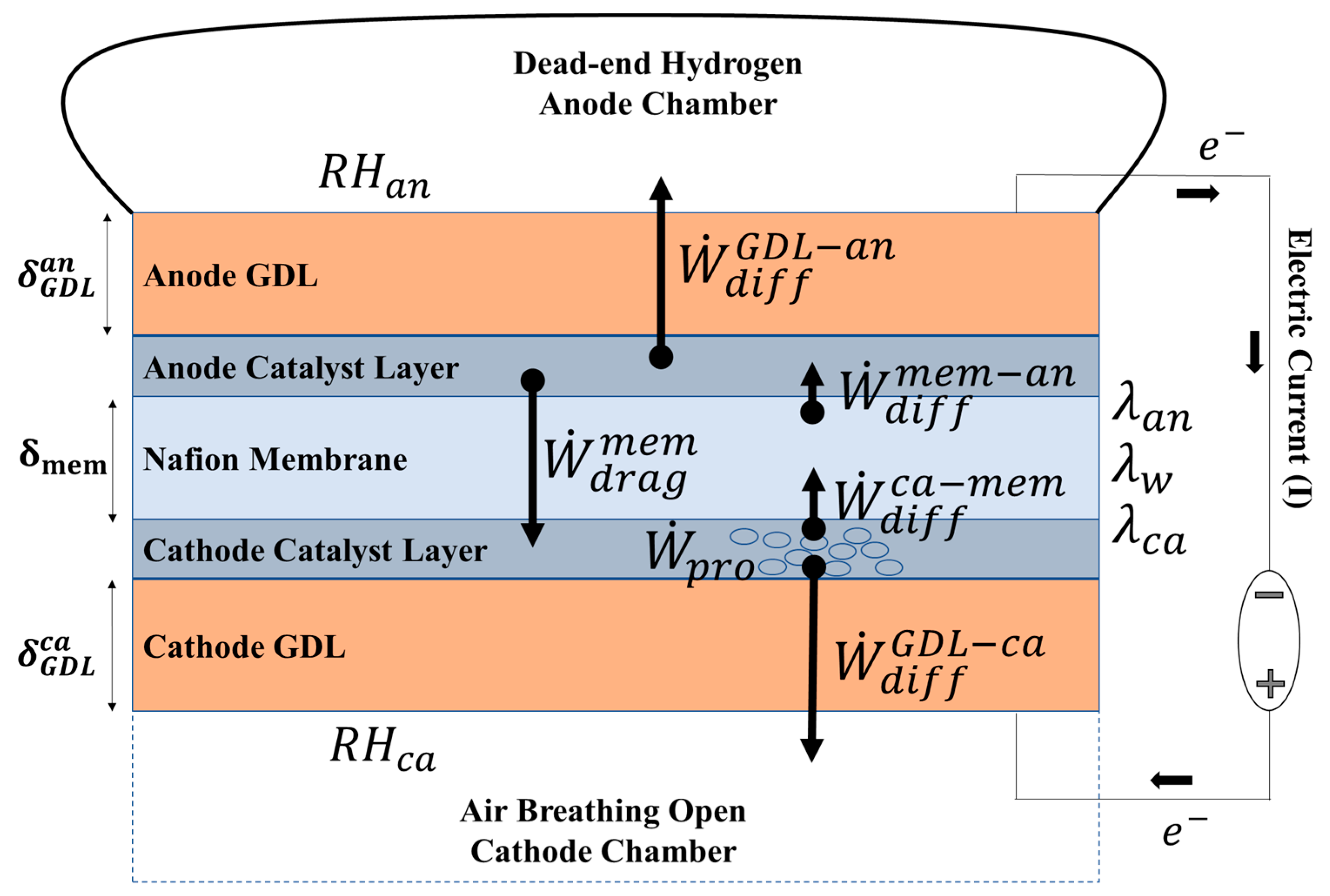
Figure 2.
The experimental setup (a schematic illustration and a photo) including a cylinder with an inflatable dead-end hydrogen storage bag (1) connected to a lightweight MEA (2), a cathode chamber (3) with ports for humid airflow (4), a weight (5), humidity sensors (6) and a Potentiostat (7).
Figure 2.
The experimental setup (a schematic illustration and a photo) including a cylinder with an inflatable dead-end hydrogen storage bag (1) connected to a lightweight MEA (2), a cathode chamber (3) with ports for humid airflow (4), a weight (5), humidity sensors (6) and a Potentiostat (7).
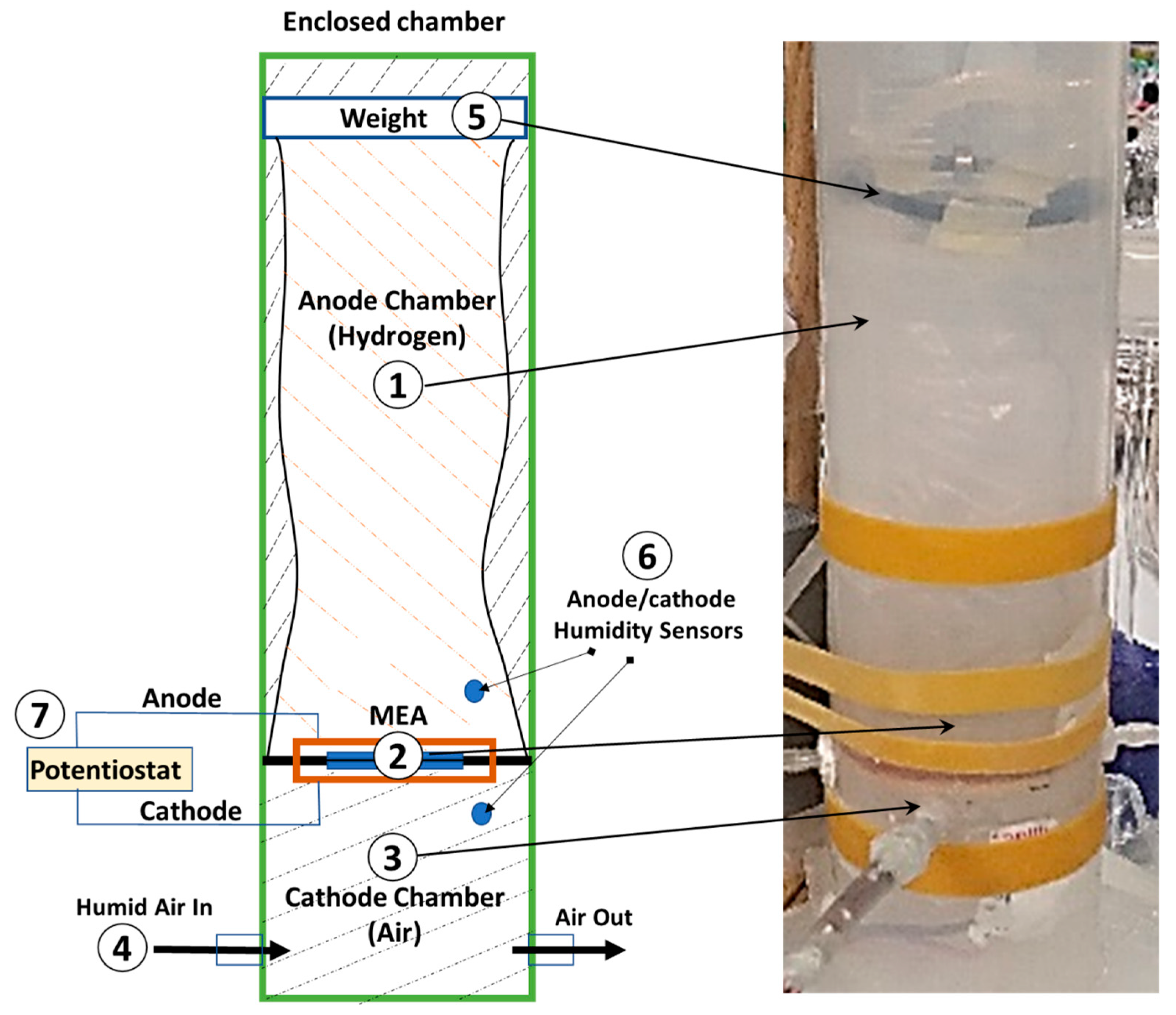
Figure 3.
Experimental result of (a) polarization test (overpotential vs. current) and (b) Power at selected humidity levels.
Figure 3.
Experimental result of (a) polarization test (overpotential vs. current) and (b) Power at selected humidity levels.
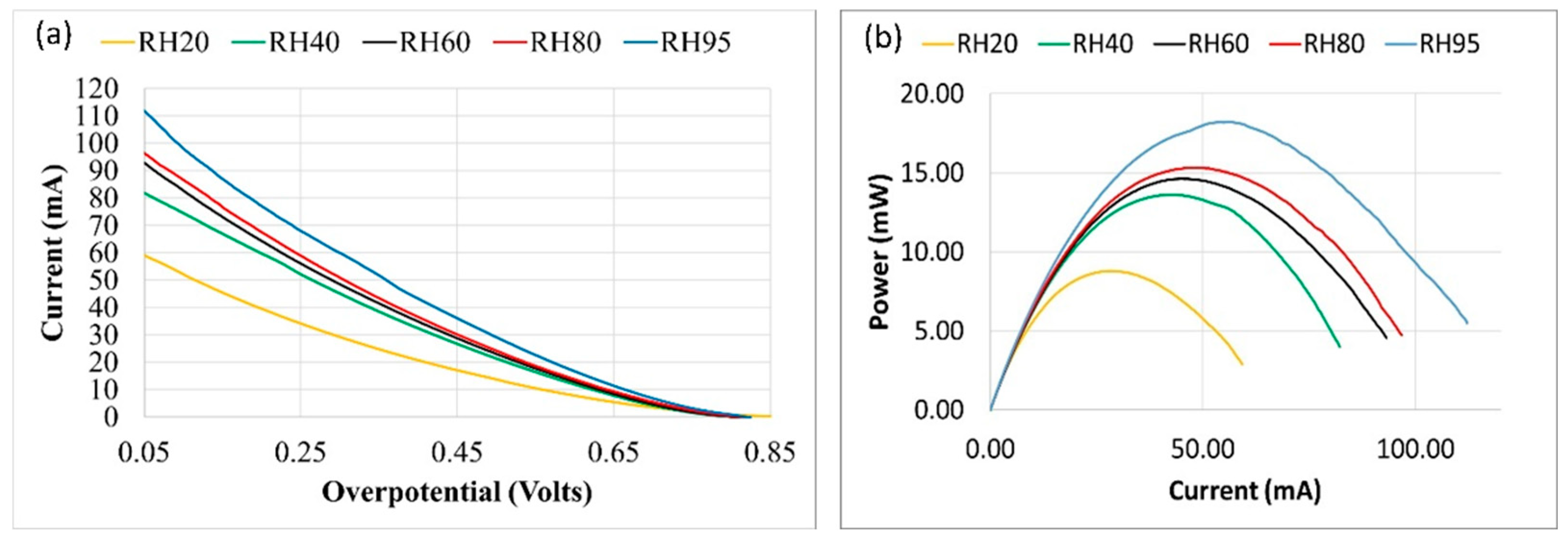
Figure 4.
Membrane resistance vs. humidity. The solid line is of the experimental results of the impedance test (fixed cathode & anode humidity), and the dashed lines are of the model with varying currents (fixed cathode & steady state anode humidity).
Figure 4.
Membrane resistance vs. humidity. The solid line is of the experimental results of the impedance test (fixed cathode & anode humidity), and the dashed lines are of the model with varying currents (fixed cathode & steady state anode humidity).
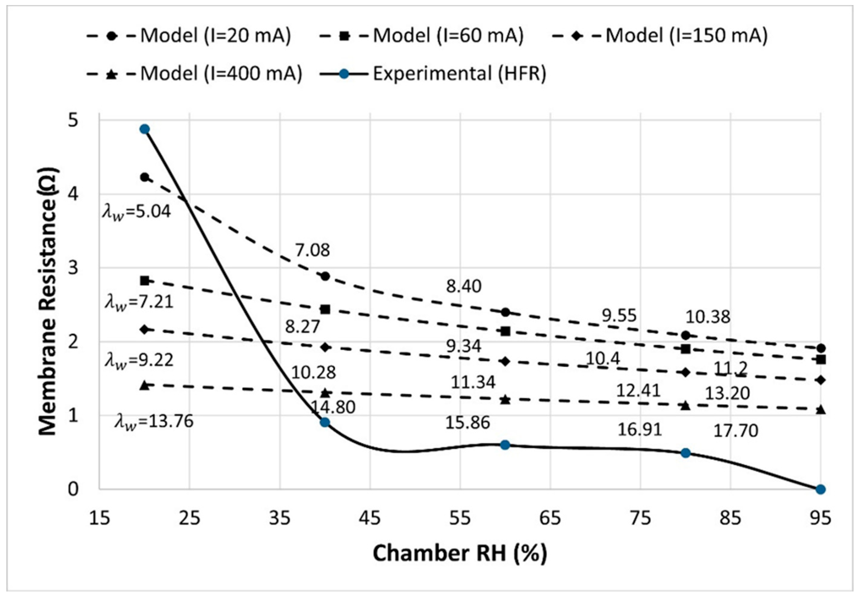
Figure 5.
Comparisons between experimental (solid lines) and model (dashed lines) results of humidity in the bag vs. time at varying current levels) at a) RHca=% 20, (b) RHca =% 50, (c) RHca =80%.
Figure 5.
Comparisons between experimental (solid lines) and model (dashed lines) results of humidity in the bag vs. time at varying current levels) at a) RHca=% 20, (b) RHca =% 50, (c) RHca =80%.
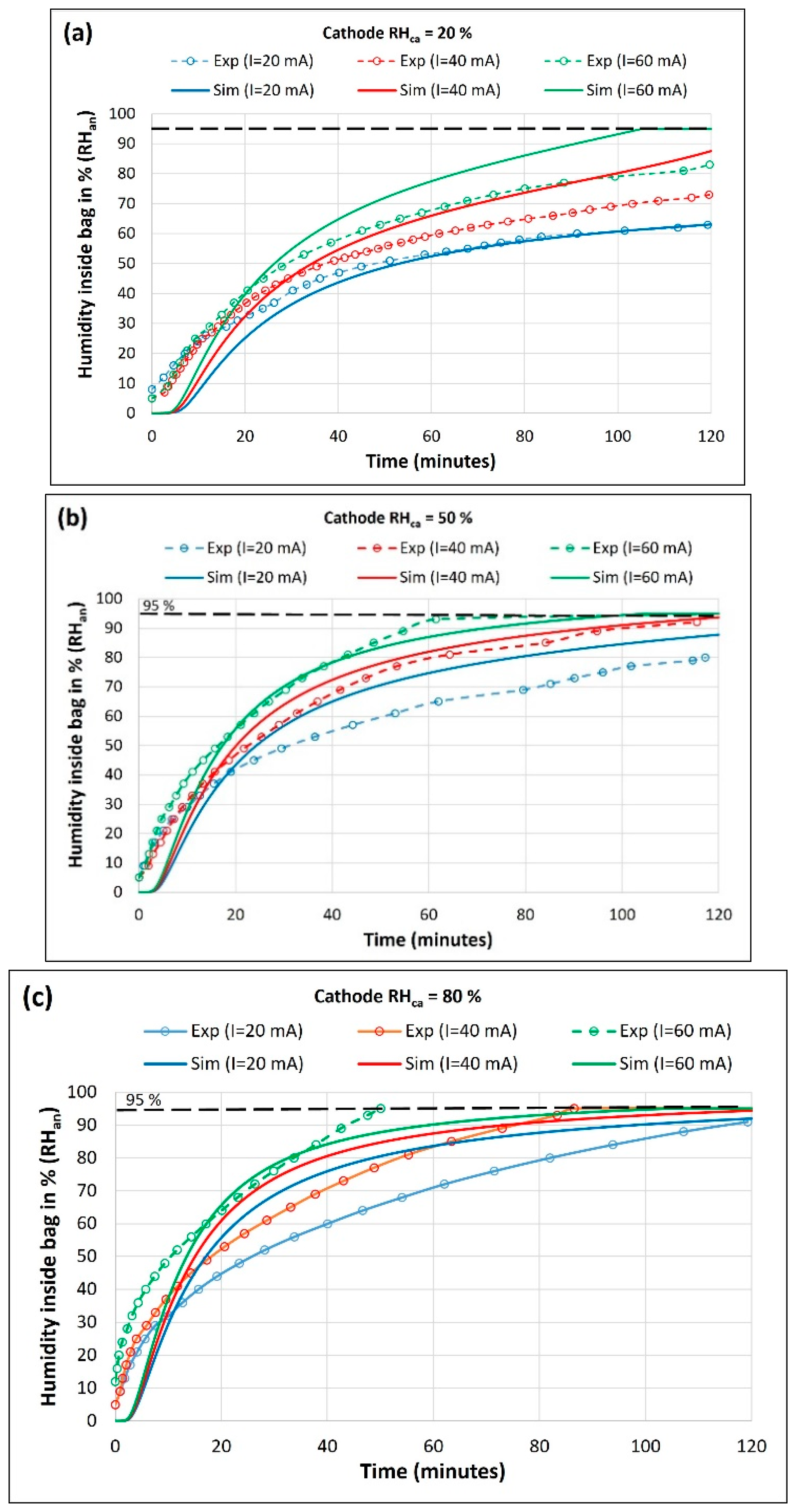
Figure 6.
Model prediction on the effect of membrane thickness on (a) Membrane Water content vs. time and (b) Membrane resistance vs. time.
Figure 6.
Model prediction on the effect of membrane thickness on (a) Membrane Water content vs. time and (b) Membrane resistance vs. time.
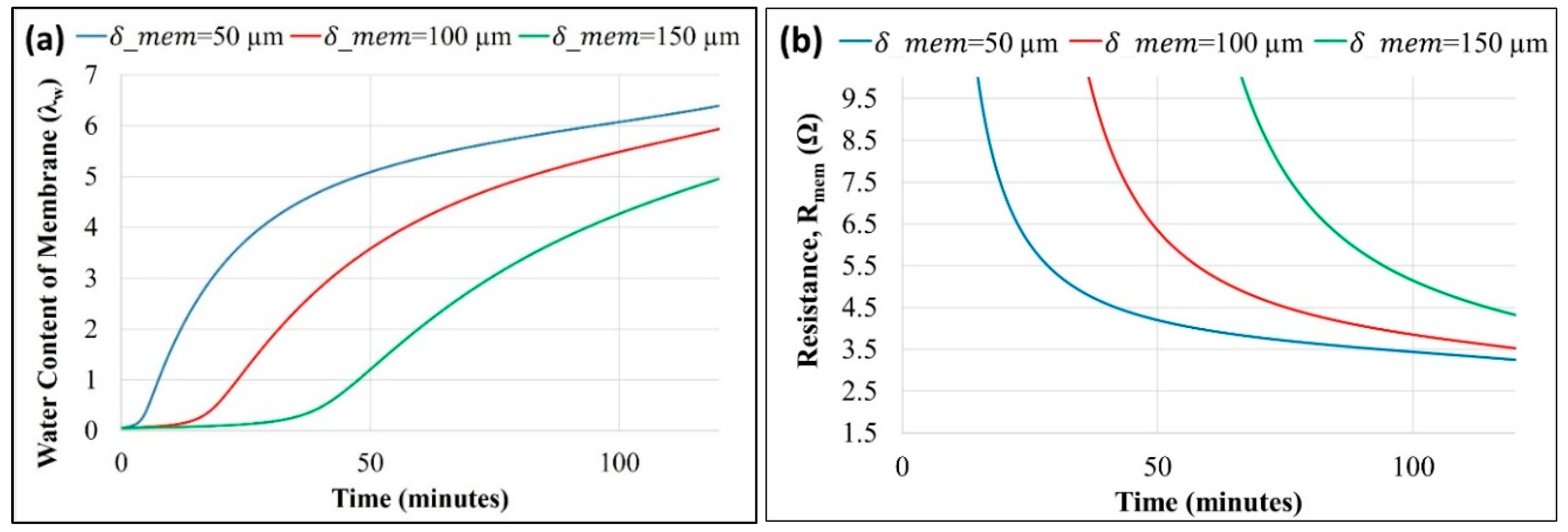
Figure 7.
Model prediction on the effect of GDL thickness (a) Membrane water content vs. time and (b) Membrane resistance vs. time.
Figure 7.
Model prediction on the effect of GDL thickness (a) Membrane water content vs. time and (b) Membrane resistance vs. time.
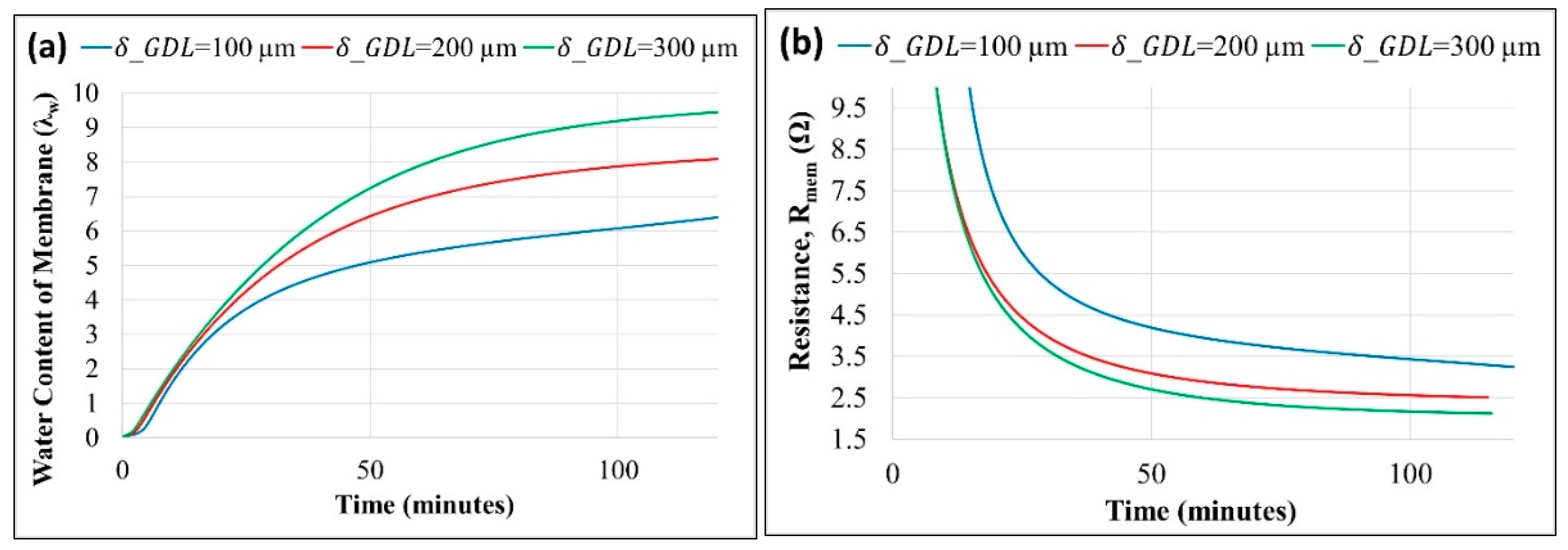
Figure 8.
Model prediction on the effect of bag volume (a) Anode’s bag RH (RHan) vs. time and (b) Membrane resistance vs. time.
Figure 8.
Model prediction on the effect of bag volume (a) Anode’s bag RH (RHan) vs. time and (b) Membrane resistance vs. time.
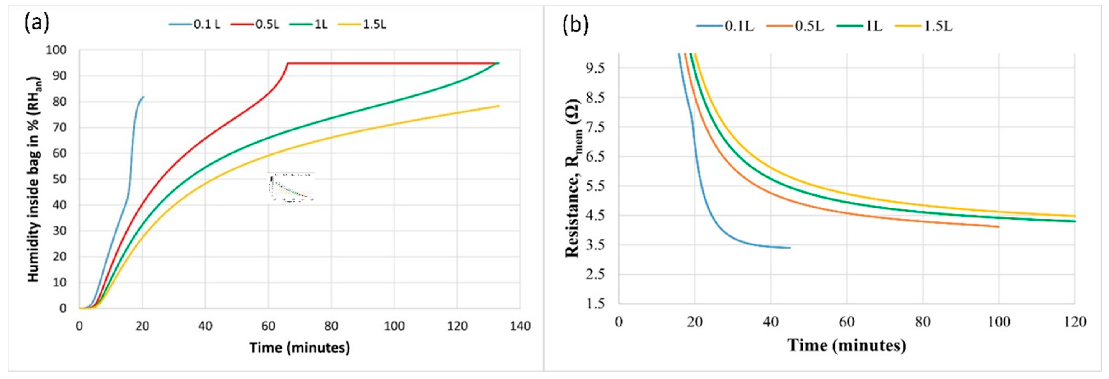

Table 1.
Base Model Parameters.
| S.No. | Parameter | Name | Value |
|---|---|---|---|
| 1 | Area of MEA | 4x10⁻⁴ m2 | |
| 2 | Thickness of membrane | ||
| 3 | Thickness of cathode GDL | ||
| 4 | Thickness of anode GDL | ||
| 5 | I | Current | 20 mA |
| 5 | Cathode chamber humidity | 0.2 | |
| 6 | V0 | Bag initial volume | 1 liter |
Disclaimer/Publisher’s Note: The statements, opinions and data contained in all publications are solely those of the individual author(s) and contributor(s) and not of MDPI and/or the editor(s). MDPI and/or the editor(s) disclaim responsibility for any injury to people or property resulting from any ideas, methods, instructions or products referred to in the content. |
© 2023 by the authors. Licensee MDPI, Basel, Switzerland. This article is an open access article distributed under the terms and conditions of the Creative Commons Attribution (CC BY) license (http://creativecommons.org/licenses/by/4.0/).
Copyright: This open access article is published under a Creative Commons CC BY 4.0 license, which permit the free download, distribution, and reuse, provided that the author and preprint are cited in any reuse.


