
Submitted:
30 October 2023
Posted:
30 October 2023
You are already at the latest version
Abstract
In this work we present a versatile, rapid, and low-cost manufacturing technique to develop bioceramic scaffolds that could enhance bone tissue regeneration via microwave preparation using a commercial microwave oven. The scaffolds were prepared combining hydroxyapatite and water glass (sodium trisilicate solution), foamed by using a microwaves oven and then characterized by means of SEM-EDS, mechanical properties, infrared spectroscopy (ATR-FTIR), density and stability test in water. Furthermore, in vitro tests were performed to verify the affinity of osteoclast cells versus the so prepared scaffold. The morphology of the samples showed interconnected pores suitable for promoting tissue regeneration and vascularization while specific mechanical properties were preserved. The physicochemical characterization and the in vitro tests presented promising results for bone regenerative applications.
Keywords:
Microwave
; Foaming Bone Scaffold
; Sodium Trisilicate
; Hydroxyapatite
; In Vitro Tests
1. Introduction
Bone transplantation is the second most common form of implant after blood transfusion (Wang & Yeung, 2017). The increase in bone-related defects or disorders is predominantly due to the increasing lifespan of the population, which makes bone transplants and bone implants in high demand (Chocholata et al., 2019).
To find solutions for emerging problems, we utilize the tools provided by tissue engineering, which, as noted by Berthiuame (Berthiaume et al., 2011), interconnects many disciplines such as materials science, mechanical engineering, clinical medicine, and genetics. It's important to emphasize that in tissue engineering, there are three main components for effective repair and growth of the tissue using artificial material. These components are (i) a scaffold to act as a support template at the site of the defect, (ii) the corresponding cells for the type of tissue being repaired, and (iii) a growth factor. The primary objective of tissue engineering is to restore and improve tissue function by preparing porous three-dimensional scaffolds and seeding them with cells and growth factors (Chaudhari et al., 2016; Chocholata et al., 2019).
We define scaffolds as Venkatesan and Kim (Jeong et al., 2019; Venkatesan & Kim, 2014) do: a bone scaffold is a porous structure inserted into bone defects to help regenerate the surrounding tissues and mechanically support the tissues for stable positioning. There is a need for mechanically porous and cost-effective structures in the field of tissue engineering. Numerous materials are used in this domain with varying clinical outcomes. Nevertheless, engineering the ideal scaffold presents its own challenges. The desired properties include biocompatibility, biodegradability, bioactivity, the presence of interconnected pores and suitable mechanical properties. Knowledge of the materials' properties constituting the bones, as well as the balance between the scaffold's porous architecture and mechanical properties that allow cell infiltration, is essential to meet this challenge.
Hydroxyapatite (HAp), a calcium phosphate-based ceramic, is often selected as the primary material or component of the material used in bone scaffolds. Since HAp is the main inorganic component of bone, artificially produced nano-Hap (n-Hap) is also recognized for its biocompatibility and has been adopted as a material for synergistic antibacterial strategies. Furthermore, it has consistently shown excellent performance in bone induction, bone conductivity, and cell adhesion (O’Brien, 2011; Venkatesan & Kim, 2014).
Among the materials recently used for scaffold production is sodium silicate in solution (water glass, WG) in combination with hydroxyapatite. This combination has allowed the synthesis of promising scaffolds, starting from processes at room temperature, as seen in ((Lakrat et al., 2021)), whereWG was used as a mineral binder for the consolidation of n-HAp through a dehydration-drying process at near-room temperature (37 °C). The new consolidation process preserves the low crystallinity, non-stoichiometry, and nanosize of the precursor n-HAp, which are essential to mimic bone tissue.
Recent applications also seem promising, as reported by Yang (Yang et al., 2022) who utilized microwaves to take advantage of the foaming nature of WG, resulting in a rapid fabrication route, yielding pure WG foams with high, tunable porosity (up to 94%) and sizes of up to tens of centimeters within a few minutes.
We started with these foundations to attempt to construct a scaffold using a commercial kitchen microwave oven and characterized it. The prepared composite scaffolds were characterized by physicochemical and morphological analyses. Additionally, in vitro biological tests were performed to verify bioactivity, biodegradability, and biocompatibility, to ensure that an equivalent result has been achieved compared to what is obtained using a laboratory microwave oven (Yang et al., 2022). The results are encouraging and suggest continuing the study to benefit from a rapid and cost-effective production method.
2. Materials and Methods
Ethanol 96%, CaO (anhydrous, powder), H3PO4 (85%), NaHCO3, sodium trisilicate solution (water glass, WG) and fumed silica (SiO2) were purchased from Merck KGaA (Darmstadt, Germany). All reagents and chemicals were of reagent grade. Deionized water was used for preparing both the used solutions and bath to rinse samples.
Hydroxyapatite (HAp) was synthesized via wet chemical technique using precipitation reaction, in which CaO and H3PO4 were used as precursors as described elsewhere in literature by Dorozhkin in 2010 (Dorozhkin, 2010).
The composite samples were prepared by mixing HAp, WG and fumed silica in a 50 ml Falcon test tube according to Table 1, for sample A, NaHCO3 was also added. To obtain homogenization of the samples a vortex mixer was employed. The tube lid was left partially open to allow the generate steam to escape and not to exert excessive pressure that could affect the formation of pores or lead to loss of material from the mould. The tube was then inserted in the microwave oven (SAMSUNG M/O 20LT GE71A of 20 L) using a borosilicate beaker as a pedestal and then heated at 450 W for 15 minutes. The hot samples were taken out from the microwave oven and dried in air for 15 minutes and then again heated at 450 W for 15 minutes until constant weight was reached. Samples were prepared in triplicate. NaHCO3 was used to guarantee the supply of CO2 to promote the geopolymerization, as suggested in the literature (Alex et al., 2013).
Thanks to the continuous monitoring and the parameters adopted for the microwave-assisted thermal treatments during the manufacturing process (MWMP), the temperature never exceeded 180 °C, as verified with an infrared camera (model SEEK Thermal Compact Pro), and shown in Figure 1, both for samples prepared in the Falcon test tube (A) or in silicon mould (B).
2.1. Physicochemical Characterization
Water stability tests were performed to test the dissolution of the samples. For this purpose samples where immersed in 1 L of distilled water (27 °C laboratory temperature) up to ten days. At different stages the samples were weighted, after drying to reach a constant weight.
The apparent density of the samples was determined with a Mettler Toledo (Mettler AE 240) precision balance (ASTM International, 2013).
Fourier transform infrared spectroscopy in attenuated total reflectance mode (ATR-FTIR) was performed using a Perkin Elmer Spectrum 2, in the range of 4000 to 400 cm-1 with a resolution of 0.5 cm-1, 16 scans.
The morphological analysis of the HAp particles and developed composite samples were evaluated by a Scanning Electron Microscopy (SEM): a Hitachi TM3000 benchtop SEM (operating at 15 kV) implemented with a probe for energy dispersive X-ray analysis (EDX) was used.
Mechanical properties of the materials were investigated by means of uniaxial compression tests performed with a Shimadzu (Kyoto, Japan) ASG-X universal testing machine operating at R.T. with a load cell of 10 kN. Cylindrical-shape specimens (20 mm in height and 25 mm in diameter) blade-cut from longer cylinder were compressed up to 30% of their initial height with a compression speed of 10 mm/min. The mechanical properties were measured on three samples for each sample and the results reported as their average.
2.2. In Vitro Biological Tests
To perform the conditioning of the samples for the in vitro biological test, the scaffolds were placed in a 24-well plate for conditioning for 4 weeks with 1 mL of Phosphate Buffered Saline (PBS) and PBS was changed two times for each week.
Human Fetal Osteoblasts (hFOB 1.19 ATCC CRL-11372TM) were used for cytotoxicity tests. Cells were grown using DMEM/F12 no phenol red with L-glutamine (Gibco, Thermo Fisher Scientific, USA) supplemented with 10% fetal bovine serum (FBS) and 0.3 mg/ml G418 (Gibco, Thermo Fisher Scientific, USA) at 37 °C in an atmosphere with 5% CO2. Cells were detached by using trypsin-EDTA (0.25% w/v trypsin and 0.03% w/v EDTA), centrifuged, and the cell number and cell viability were assessed with a trypan blue dye exclusion test. The composite scaffolds (width = 8 mm and height = 5 mm) were washed in deionized water in a sonicating bath for 30 minutes before sterilization. All scaffold types (COMPACT, A and C) were then sterilized with ethanol 70% for 30 minutes, then the samples were left dry under the sterile laminar flow hood for 1 hour. Samples were pre-soaked in culture medium for 24 h at 37 °C, and then seeded by carefully dropping 20 µl of cell suspension (5.0×10⁴ cells) onto the scaffold upper surface and allowing cell attachment for 30 min in the incubator, before the addition of 980 µl of cell culture medium. The medium was changed every 3 days. All cell handling procedures were performed in a sterile laminar flow hood. All cell-culture incubation steps were performed at 37 °C with 5% CO2.
Qualitative cell viability and cytotoxicity analyses were performed for each group after 1 day by using a Live/Dead™ Assay Kit (Invitrogen, Thermo Fisher Scientific, USA) according to manufacturer’s instructions. Briefly, cells were rinsed in PBS before incubation with acetoxymethyl calcein (AM-calcein) 2 µM and ethidium homodimer-1 (EthD-1) 4 µM for 15 min at 37 °C in dark conditions. Samples were rinsed in PBS, and images were acquired by an inverted fluorescent microscope Eclipse TS 100 (Nikon, Japan).
Quantitative cell viability and proliferation analyses of cells seeded on scaffolds were performed by PrestoBlue™ Cell Viability Reagent procedure (Invitrogen, Thermo Fisher Scientific, USA) according to manufacturer’s instructions. Briefly, 10% (v/v) of PrestoBlue Reagent were added for each well containing the scaffold and incubated for 2 h at 37 °C with 5% CO2. For each timeframe three samples were used. Additionally, a scaffold without cells was used according to the same procedure and then considered as a blank in the data elaboration. After the incubation 100 µL of supernatants were removed from each well and transferred in a 96-well plate, each of them in triplicate. The resulting 96-well plate was then analyzed using the Fluoroskan™ Microplate Fluorometer (Thermo Fisher Scientific, USA) setting the excitation wavelength equal to 544 nm, whereas the emission wavelength to 590 nm. The same set of analyses were performed at different timeframes equal to 1 and 3 days after cell seeding.
One sample per group was used for actin staining 3 days after cell seeding. In order to visualize actin filaments, seeded materials were washed with PBS, fixed with paraformaldehyde 4% (w/v) for 15 minutes and then incubated in Triton X-100 0.1% (v/v, PBS as solvent) for 10 minutes to promote cell permeabilization. Cells were incubated with ActinRed™ 555 ReadyProbes™ Reagent (Rhodamine phalloidin) (Thermo Fisher Scientific, USA) for 30 minutes. Cells were then incubated with DAPI 300 nM in PBS for 10 minutes. Finally, scaffolds were transferred on a coverslip with a drop of PBS and then visualized by an inverted fluorescent microscope Eclipse TS 100 (Nikon, Japan).
2.3. Statistical Analyses
Statistical analysis and graph elaboration were performed using GraphPad Prism 9.0.0 (GraphPad Software, San Diego, CA). One-way ANOVA (analysis of variance) was performed followed by Dunnett’s multiple comparisons test to evaluate differences. Differences were considered significant for p-values less than 0.05 (* p-value < 0.05; ** p-value < 0.01; *** p-value < 0.001; **** p-value < 0.0001).
To perform the conditioning of the samples for the in vitro biological test, the scaffolds were placed in a 24-well plate for conditioning.
3. Results and Discussion
3.1. Solubility and Density Evaluation
Considering that scaffold solubility, a crucial aspect in bone regeneration, is a complex property, we conducted experiments to ensure that the scaffolds did not completely dissolve in water, maintaining their structural integrity without releasing ions that could potentially alter the pH and result in toxicity.
For this purpose, we weighed the samples and immersed them in deionized water in a 10-liter container, ensuring that the water was changed every 24 hours. After a period of 10 days, we retrieved the samples and reweighed them, confirming that there were no significant weight variations. To ensure the absence of any unreacted NaO, we introduced NaHCO3 and monitored the pH, which initially registered a value of 12 before stabilizing at neutral levels.
Density value of the foamed WG sample corresponding to 0.2 g/cm3 that value increases up to 0.5 g/cm3 adding SiO2 and HAp, the density value series is summarized in Table 1. It is interesting to note that the sample containing WG and a double quantity of SiO2 has the same density as that containing WG, SiO2 and HAp in equal quantities. However, the composite containing SiO2 and HAp is preferred due to the ability of HAp to impart a greater affinity towards osteoblasts compared to SiO2.
3.2. Morphological Analysis
The total average porosity of the (COMPOSITE) HAp-WG scaffold was determined to be around 60% for all samples, calculated considering the volume and weights of 3 specimen for each sample in exam (for comparison, cancellous bone porosity is in the interval between 30% and 80%). The porosity %, varying between 35% and 80%, presents a great ability to induce osteointegration and enhancing implant adhesion to the host tissue (Zubair et al., 2020).
The as-prepared HAp morphology was investigated by SEM analysis The particles have submicrometric features reported in Figure 2. Energy-dispersive X-ray spectroscopy (EDS) (not reported) analyses showed the presence of calcium (Ca), phosphorus (P), oxygen (O) and carbon (C) in a percentage amount compatible with the HAp particles composition. Due to its chemical composition, nonstoichiometric and low crystallinity, it is an optimal candidate to be used in scaffolds design and preparation.
SEM images of the prepared 3D composite scaffolds (Figure 3, Figure 4 and Figure 5) point out a densified and cohesive material, where HAp particles are fully covered and integrated within the WG. Sample COMPACT, prepared with the addition of an equal quantity of WG and HAp, shows the formation of a smooth continuous surface, while for samples (A) and (B), where a larger quantity of WG was present, we can notice the present of fractures of bubble-like shape. Addition of NaHCO3, that increases the foaming and geopolymerization of the water glass, here did not cause a difference in the morphology of the samples (A) and (B).
3.3. Compressive Tests
In Figure 6 the results related to all the samples are depicted, whereas in Figure 7, the results of only those samples created for the purpose of a more detailed study of the hydroxyapatite quantity effect are shown. When examining the curves derived from the samples employed in the biological tests, it becomes evident, as depicted in Figure 8, that the COMPACT sample displays abetween, exhibitscurve with a profile characterized by the absence of small noise spikes, as expected, due to the compact nature of the sample. In contrast, for the A and C samples there is a fluctuation in values due to the porous nature of the samples and the collapse that occurs.
3.4. ATR-FTIR Results
ATR-FTIR spectra of the composite scaffolds COMPACT, A and C reported in Figure 9. Figure 9 show the typical vibration bands of HAp particles before their consolidation by MWMP. The widening of the peak near 1000 cm-1 can be attributes top the peaks of WG relating to the Si–O band around 850 cm-1. Peaks in the range of 950 cm-1 to 1100 cm-1, assigned to Si–O–Si are overlapping with phosphate groups in HAp structure. An increase in the intensity of the carbonate bands, located between 1400 and 1500 cm-1 is also evident. Always observing figure 4, the phosphate group (PO43-) shows the characteristic band near 600 cm-1 (in our case 593-561cm-1) (ν4). Furthermore, their characteristic band for HAp at 960 cm-1 (ν1) and 1030, 1081 cm-1 (ν3) are present. Small vibration bands at ~860 cm-1, 1420 and 1460 cm-1 (ν3), which correspond to carbonate ions, are also present. According to literature data Koutsopoulos, 2002), bands suggest that the as prepared phase is a B-type carbonated apatite. The ATR-FTIR spectrum of microwaved dried water glass (Figure 4) presents a large band around 950 cm-1 and a smaller one at 880 cm-1. They can be attributed to the asymmetric stretching of Si–O–Si band which can be assigned to the Q2 and Q1 silica units respectively (VERWEIJ & KONIJNENDIJK, 1976). No water seems present (stretching between 3600 cm-1 and 2700 cm-1 with a small vibrational band at 1650 cm-1 are absent from our spectra). No carbonates are present because in that case, asymmetric stretching band at 1435 cm-1 would have been present.
3.5. Effects of Scaffolds on Osteoblasts Viability
Considering the potential use of hydroxyapatite-base scaffolds for bone regenerative medicine, and that the interaction of materials and devices with cells determines the successful outcome of the implant (Huang et al., 2005), we next sought to investigate their interaction with hFOB cells. The latter is a validated and widely used cell culture model to study the potential of materials intended for regenerative approaches since osteoblasts are the main component of bone tissue and are the main cells involved in the interaction with the implanted material (Balani et al., 2007; Zhang et al., 2008). To this aim, cells were seeded on scaffolds to determine the impact of the scaffolds on osteoblasts viability, adhesion, and morphology. We then investigated the cell viability by adopting a qualitative and quantitative assay.
Live/Dead assay allows the discrimination of live cells from dead cells by simultaneously staining their esterase activity and their loss of plasma membrane integrity, respectively. According to these analyses viable cells are stained in green, whereas dead cells in red. Considering Live/Dead assay it is possible to appreciate that only live osteoblasts were detected after 1 day in all scaffolds (Figure 10 Figure 10). These results suggest that scaffolds based on hydroxyapatite and water glass are not cytotoxic.
The viability and proliferation of human osteoblasts were then quantitatively investigated by PrestoBlue assay, according to which the fluorescence intensity is proportional to the cell metabolic activity and correlates to the cell proliferation (Sagnella et al., 2016). After 1 day a comparable cell viability in all scaffolds was detected (Figure 11), similarly to the qualitative trend detected by Live/Dead assay (Figure 10 Figure 10). After 3 days a significant increase in the cell viability was detected (for all scaffold types day 1 vs. day 3 p-value < 0.0001) suggesting that scaffolds significantly support osteoblasts proliferation. On the other hand, a lower cell viability was detected for the C scaffolds suggesting that a partial release of their components partially limited cell proliferation.
3.4. Effects of Scaffolds on Cell Morphology
The appropriate cell interaction with the implanted materials is crucial to determine the successful cell colonization and integration with the native tissues, and therefore affects the outcome of the regeneration approach (Huang et al., 2005). Specifically, cell adhesion to the biomaterial affects the consequent cell proliferation and involves complex processes, especially the reorganization of cytoskeleton proteins like actin. Considering the potential use of scaffolds for bone regenerative medicine, we investigated the influence of the scaffolds on the organization of F-actin filaments of osteoblasts (Figure 12).
Three days after cell seeding the typical osteoblasts phenotype well-adherent to the biomaterial was detected, suggesting a good cell adhesion to the different types of scaffolds. In addition, also the typical round shape nuclear morphology confirmed the absence of any evident cytotoxic effect (e. g. condensed chromatin and apoptotic bodies) (Figure 12Figure 12). Furthermore, the number of cells present on the scaffolds correlates with cell viability and proliferation data detected by PrestoBlue assay after the same timeframe and it confirms a lower number of cells seeded on sample C probably due to the release of the components from these scaffolds that partially limit the cell adhesion and spreading to these scaffolds.
Similar findings were previously reported by Lakrat and collaborators for MG63 cells incubated with nano-hydroxyapatite sodium silicate glass composite (Lakrat et al., 2021). Specifically, they incubated these osteosarcoma cells plated on plastic with different concentrations of the composite and no cytotoxicity was detected. Additionally, cells displayed the appropriate shape. Nevertheless, they did not investigate the ability of cells to adhere to the scaffolds and they used a cell model – osteosarcoma cell – which is not appropriate to investigate the potential for bone regeneration.
Different findings were previously reported by Velusamy and co-workers for a lung cancer cell line exposed to HAp nanoparticles doped with different ions (iron and zinc) and produced with a microwave-assisted reaction (Velusamy et al., 2022). In detail, a cell death coupled to a lower spreading ability proportional to the concentrations of nanoparticles cell was reported. The different results can be correlated to the presence of zinc ions which are considered as cytotoxic (Borovanský & Riley, 1989; Shen et al., 2013).
Considering these reports, scaffolds reported in the present paper resulted to be stable, without releasing any toxic compound and can be considered as safe material intended for bone regenerative medicine applications.
4. Conclusions
We successfully fabricated Na2SiO3-SiO2-HAp scaffold using a commercial microwave oven, in really short time (45 mins total), i.e. a short treatment process time if compared to classical sintering and printing techniques.
The main results were the following:
- Samples manufactured in a commercial microwave oven have a morphology comparable with samples obtained via a laboratory microwave oven or via a process involving a laboratory heater.
- Microwave foaming of WG and HAp formulations produced biocompatible scaffolds as confirmed by in vitro test.
- The time of manufacturing was reduced of an order of magnitude (and more) in comparison with non-microwave workflow.
- All the advantages of using a microwave process via a laboratory oven were retained (speed of the process, no solvent, foaming with consequently obtaining a porous structure, high reproducibility after selecting the parameters in exam and allows parameters tuning).
- In comparison with the samples obtained with a laboratory equipment it opens the possibility for rapid prototyping and to lower the cost and speed of the workflow for prototyping bone scaffolds.
Further experiments are on the way to enhance the material's mechanical properties, elevate its biocompatibility, and maximize its regenerative potential. Through modifications in the composition, incorporating a higher proportion of biological components, we aim to create a scaffold that can be confidently regarded as a safe material for use in bone regenerative medicine applications.
Author Contributions
Conceptualization, M.V. and G.L.; methodology, G.L, M.V, S.P., F.F.,M.M.; formal analysis, G.L, M.V, S.P., F.F.,M.M; investigation, G.L, M.V, S.P., F.F.,M.M.; resources, G.L, M.V, S.P., F.F.,M.M.; data curation, G.L, M.V, S.P., F.F.,M.M; writing—original draft preparation, G.L, M.V, S.P., F.F.,M.M; writing—review and editing, G.L, M.V, S.P., F.F.,M.M ,D.G., C.D.; visualization, G.L, M.V, S.P., F.F.,M.M, D.G., C.D .; supervision, D.G.,C.D; project administration, G.L, M.V; funding acquisition G.L, M.V. All authors have read and agreed to the published version of the manuscript.
Funding
This research received no external funding.
Data Availability Statement
Data are available upon request.
Conflicts of Interest
The authors declare no conflict of interest.
References
- Alex, T. C., Kalinkin, A. M., Nath, S. K., Gurevich, B. I., Kalinkina, E. V., Tyukavkina, V. V., & Kumar, S. Utilization of zinc slag through geopolymerization: Influence of milling atmosphere. International Journal of Mineral Processing 2013, 123, 102–107. [CrossRef]
- ASTM International. Standard Test Methods for Density of Compacted or Sintered Powder Metallurgy (PM) Products Using Archimedes’ Principle. Astm 2013, B962-13. Available online: https://www.astm.org/b0962-17.
- Balani, K., Anderson, R., Laha, T., Andara, M., Tercero, J., Crumpler, E., & Agarwal, A. Plasma-sprayed carbon nanotube reinforced hydroxyapatite coatings and their interaction with human osteoblasts in vitro. Biomaterials 2007, 28, 618–624. [CrossRef]
- Berthiaume, F., Maguire, T. J., & Yarmush, M. L. Tissue Engineering and Regenerative Medicine: History, Progress, and Challenges. Annual Review of Chemical and Biomolecular Engineering 2011, 2, 403–430. [CrossRef]
- Borovanský, J., & Riley, P. A. Cytotoxicity of zinc in vitro. Chemico-Biological Interactions 1989, 69, 279–291. [CrossRef]
- Chaudhari, A., Vig, K., Baganizi, D., Sahu, R., Dixit, S., Dennis, V., Singh, S., & Pillai, S. Future Prospects for Scaffolding Methods and Biomaterials in Skin Tissue Engineering: A Review. International Journal of Molecular Sciences 2016, 17, 1974. [CrossRef]
- Chocholata, P., Kulda, V., & Babuska, V. Fabrication of Scaffolds for Bone-Tissue Regeneration. Materials 2019, 12, 568. [CrossRef]
- Dorozhkin, S. V. Calcium orthophosphates as bioceramics: State of the art. Journal of Functional Biomaterials 2010, 1, 22–1074. [Google Scholar] [CrossRef]
- Huang, Y., Onyeri, S., Siewe, M., Moshfeghian, A., & Madihally, S. V. In vitro characterization of chitosan–gelatin scaffolds for tissue engineering. Biomaterials 2005, 26, 7616–7627. [CrossRef]
- Jeong, J., Kim, J. H., Shim, J. H., Hwang, N. S., & Heo, C. Y. Bioactive calcium phosphate materials and applications in bone regeneration. Biomaterials Research 2019, 23, 1–11. [CrossRef]
- Koutsopoulos, S. Synthesis and characterization of hydroxyapatite crystals: A review study on the analytical methods. Journal of Biomedical Materials Research 2002, 62, 600–612. [Google Scholar] [CrossRef]
- Lakrat, M., Jabri, M., Alves, M., Fernandes, M. H., Ansari, L. L., Santos, C., & Mejdoubi, E. M. Three-dimensional nano-hydroxyapatite sodium silicate glass composite scaffold for bone tissue engineering - A new fabrication process at a near-room temperature. Materials Chemistry and Physics 2021, 260, 124185. [CrossRef]
- O’Brien, F. J. Biomaterials & scaffolds for tissue engineering. Materials Today 2011, 14, 88–95. [Google Scholar] [CrossRef]
- Sagnella, A., Pistone, A., Bonetti, S., Donnadio, A., Saracino, E., Nocchetti, M., Dionigi, C., Ruani, G., Muccini, M., Posati, T., Benfenati, V., & Zamboni, R. Effect of different fabrication methods on the chemo-physical properties of silk fibroin films and on their interaction with neural cells. RSC Advances 2016, 6, 9304–9314. [CrossRef]
- Shen, C., James, S. A., De jonge, M. D., Turney, T. W., Wright, P. F. A., & Feltis, B. N. Relating Cytotoxicity, Zinc Ions, and Reactive Oxygen in ZnO Nanoparticle–Exposed Human Immune Cells. Toxicological Sciences 2013, 136, 120–130. [CrossRef]
- Velusamy, N., Sundarabharathi, L., & Saminathan, R. K. Microwave synthesis, characterization and antibacterial performance of dual mineralized nanohydroxyapatite for biomedical applications. Biocatalysis and Agricultural Biotechnology 2022, 40, 102303. [CrossRef]
- Venkatesan, J., & Kim, S.-K. Nano-Hydroxyapatite Composite Biomaterials for Bone Tissue Engineering—A Review. Journal of Biomedical Nanotechnology 2014, 10, 3124–3140. [CrossRef]
- VERWEIJ, H., & KONIJNENDIJK, W. L. Structural Units in K2O-PbO-SiO2 Glasses by Raman Spectroscopy. Journal of the American Ceramic Society 1976, 59, 517–521. [CrossRef]
- Wang, W., & Yeung, K. W. K. Bone grafts and biomaterials substitutes for bone defect repair: A review. Bioactive Materials 2017, 2, 224–247. [CrossRef]
- Yang, L., Haibel, A., Görke, O., & Fleck, C. Microwaves speed up producing scaffold foams with designed porosity from water glass. Materials & Design 2022, 222, 111100. [CrossRef]
- Zhang, Y., Venugopal, J. R., El-Turki, A., Ramakrishna, S., Su, B., & Lim, C. T. Electrospun biomimetic nanocomposite nanofibers of hydroxyapatite/chitosan for bone tissue engineering. Biomaterials 2008, 29, 4314–4322. [CrossRef]
- Zubair, M., Ferrari, R., Alagha, O., Mu’azu, N. D., Blaisi, N. I., Ateeq, I. S., & Manzar, M. S. Microwave Foaming of Materials: An Emerging Field. Polymers 2020, 12, 2477. [CrossRef]
Figure 1.
IR-thermal image of sample prepared into the Falcon test tube (A) and of the samples prepared into the silicon mould (B).
Figure 1.
IR-thermal image of sample prepared into the Falcon test tube (A) and of the samples prepared into the silicon mould (B).
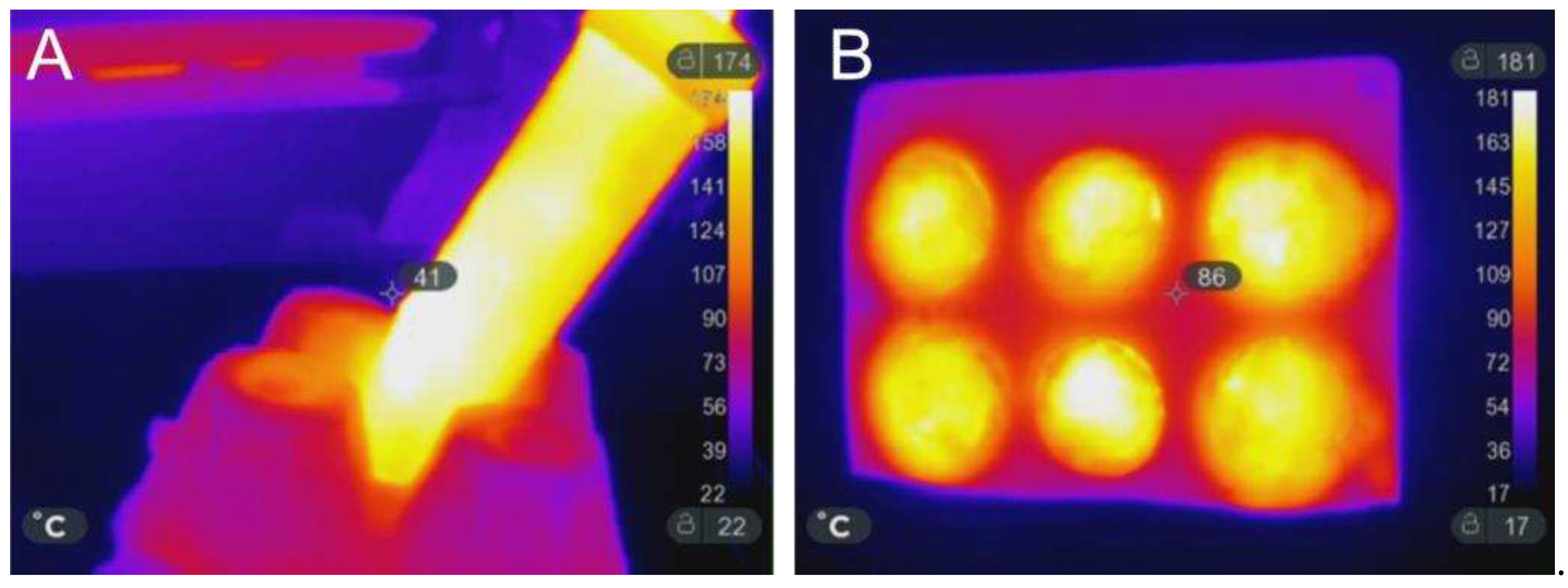
Figure 2.
SEM image of as-synthesized HAp. Bar corresponds to 10 µm for both images.
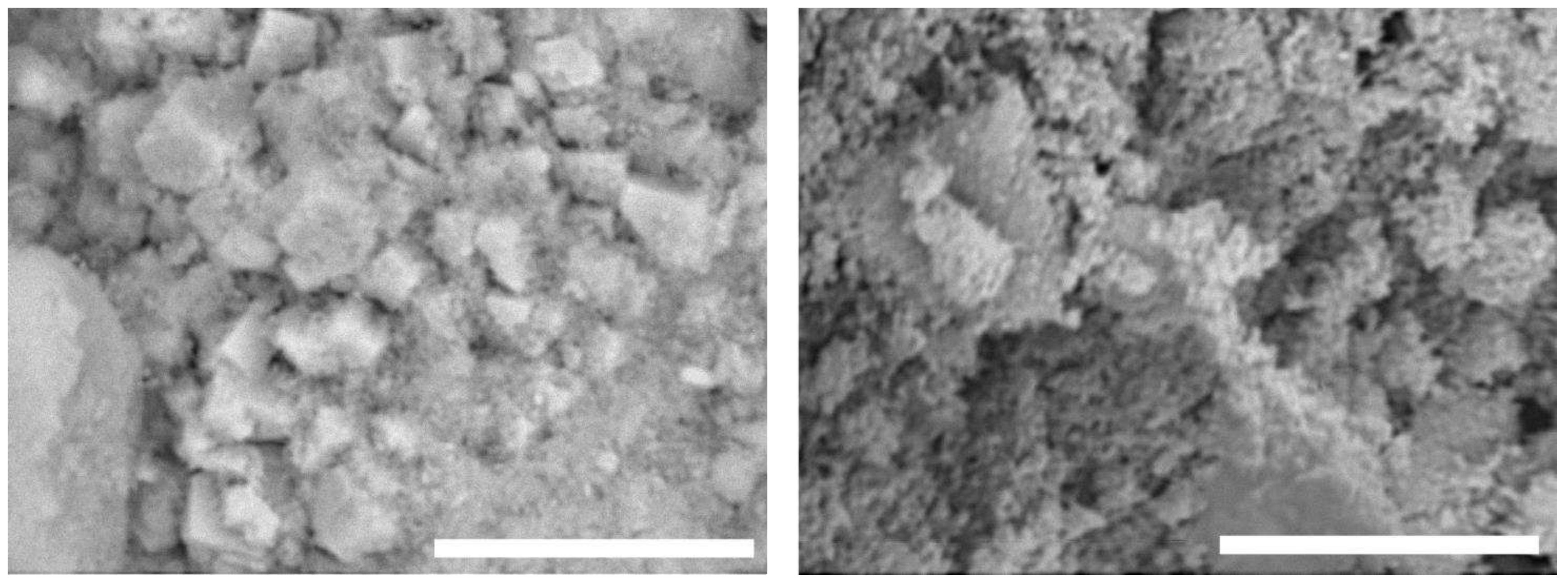
Figure 3.
SEM image of the sample COMPACT. Left 100x, middle 500x, right image 1000x. White bar corresponds respectively to 1 mm, 200 µm and 100 µm.
Figure 3.
SEM image of the sample COMPACT. Left 100x, middle 500x, right image 1000x. White bar corresponds respectively to 1 mm, 200 µm and 100 µm.
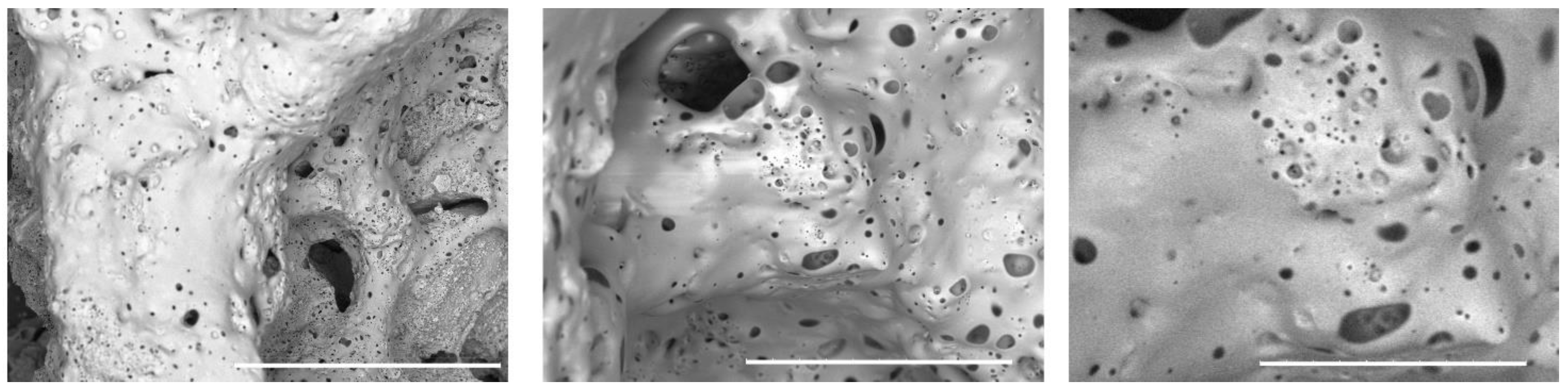
Figure 4.
SEM image of the sample A. Left 100x, middle 500x, right image 1000x. White bar corresponds respectively to 1 mm, 200 µm and 100 µm.
Figure 4.
SEM image of the sample A. Left 100x, middle 500x, right image 1000x. White bar corresponds respectively to 1 mm, 200 µm and 100 µm.
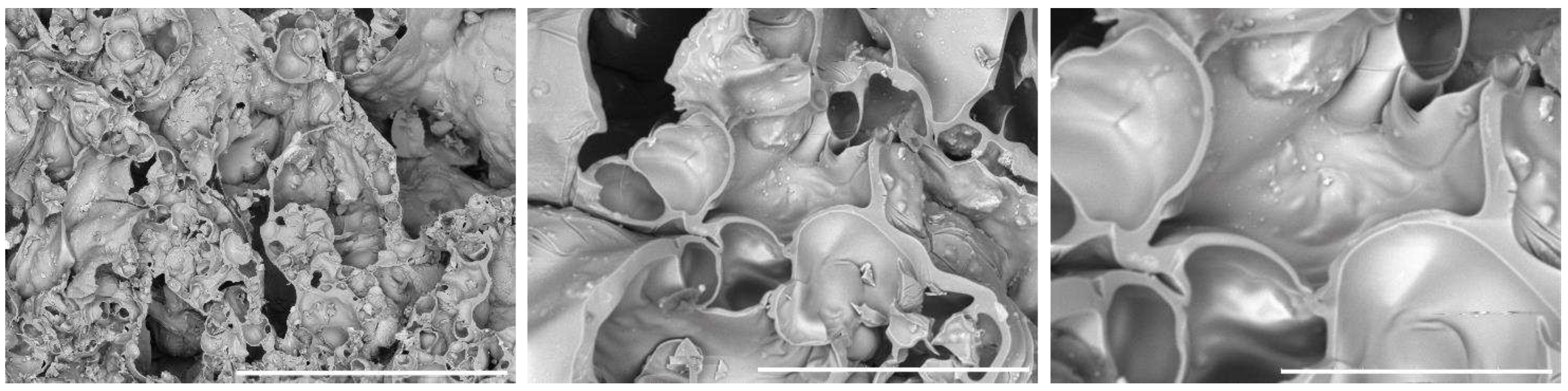
Figure 5.
SEM image of the sample C. Left 100x, middle 500x, right image 1000x. White bar corresponds respectively to 1mm, 200 µm and 100 µm.
Figure 5.
SEM image of the sample C. Left 100x, middle 500x, right image 1000x. White bar corresponds respectively to 1mm, 200 µm and 100 µm.
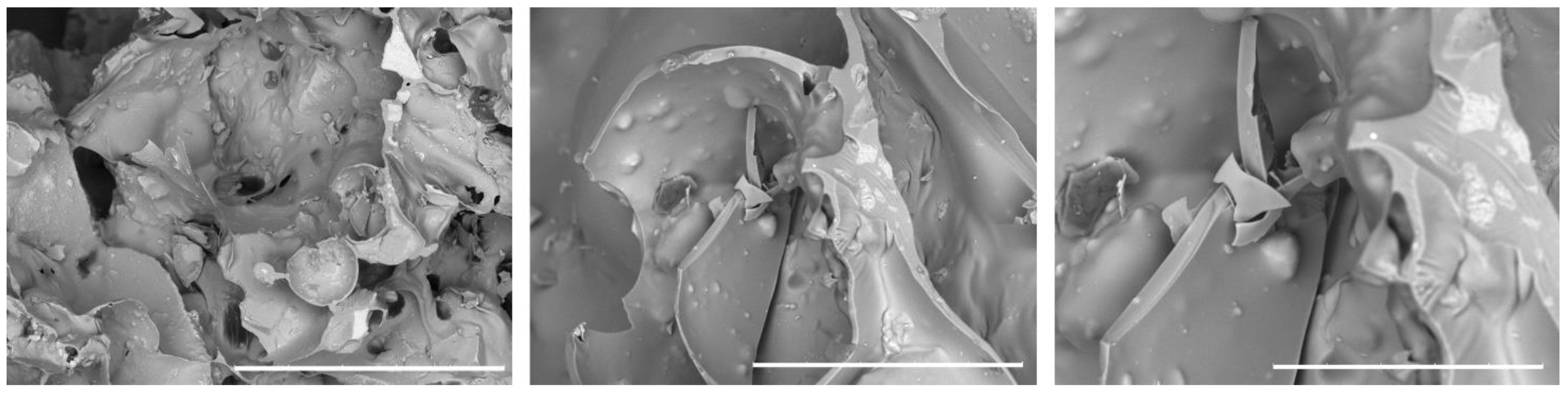
Figure 6.
Graphs of all compressive tests performed.
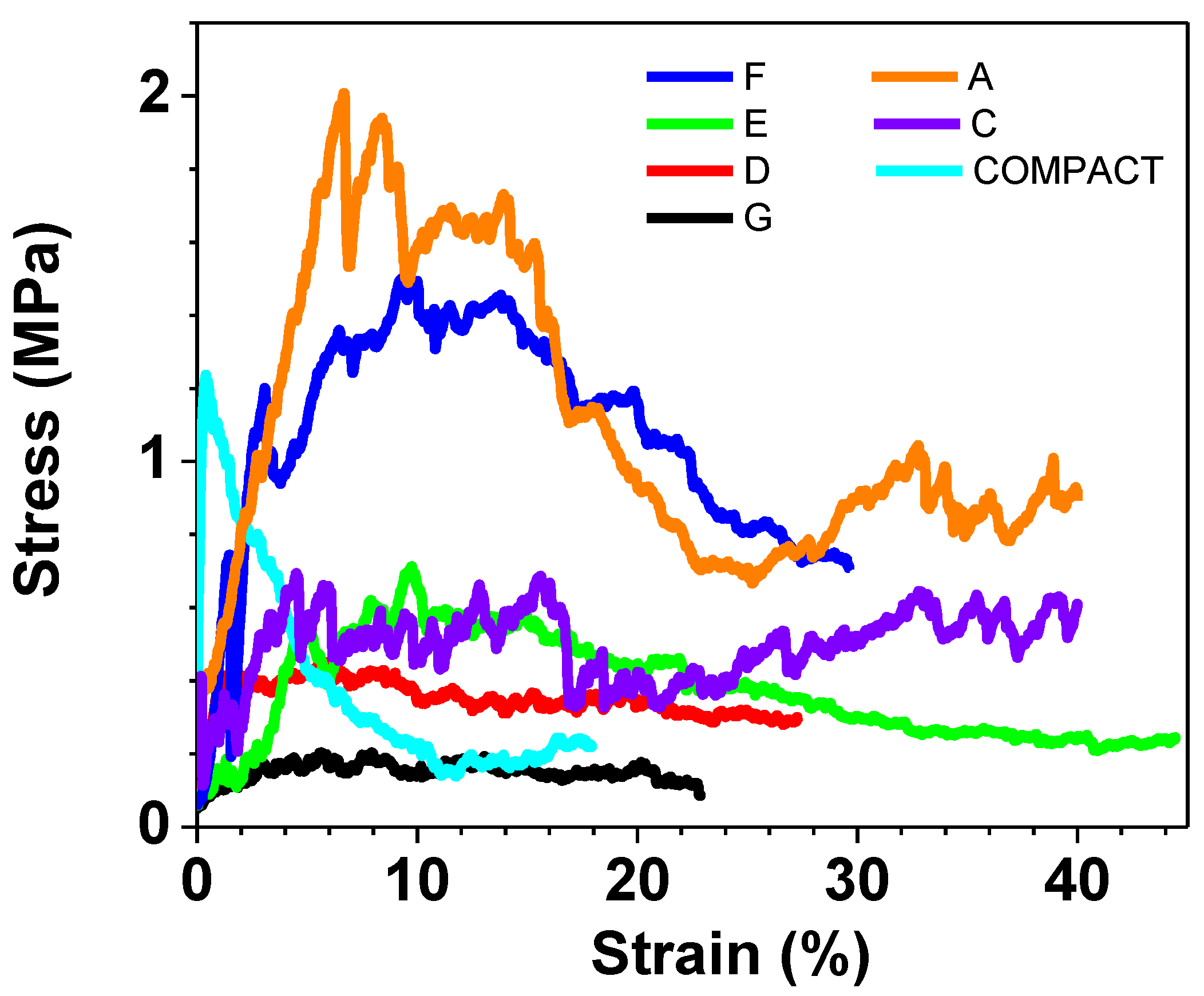
Figure 7.
Compressive tests to highlight the contribute of each component.
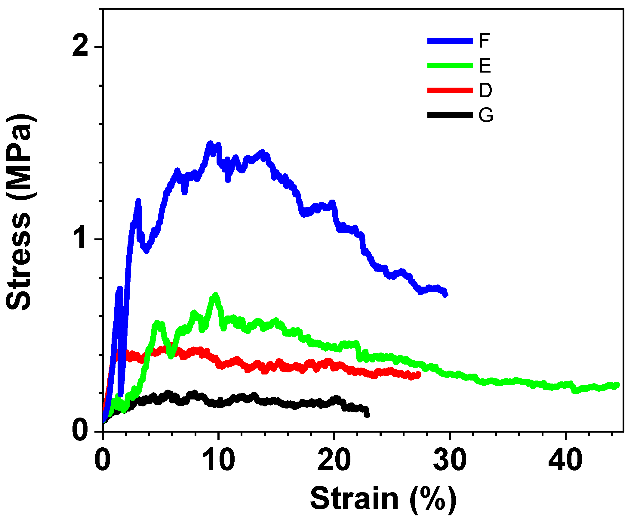
Figure 8.
Compressive tests of the in vitro tested samples.
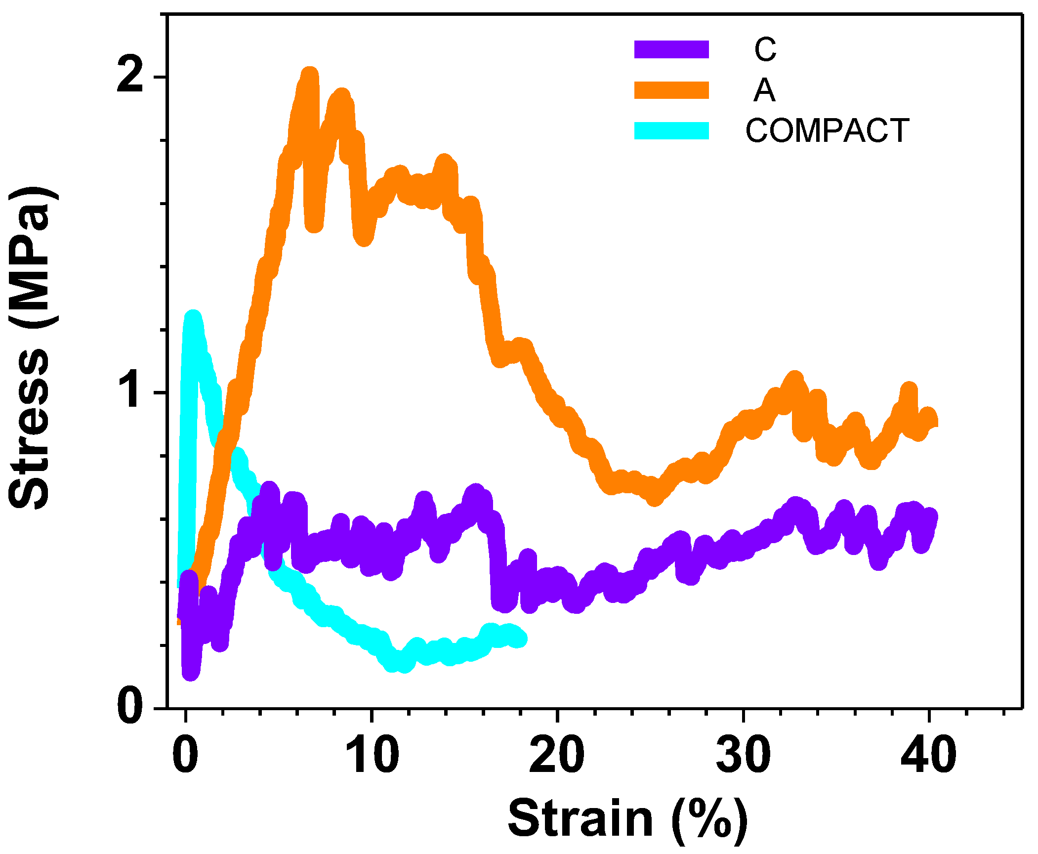
Figure 9.
ATR-FTIR spectra performed on samples: COMPACT, A, C, HAp and WG.
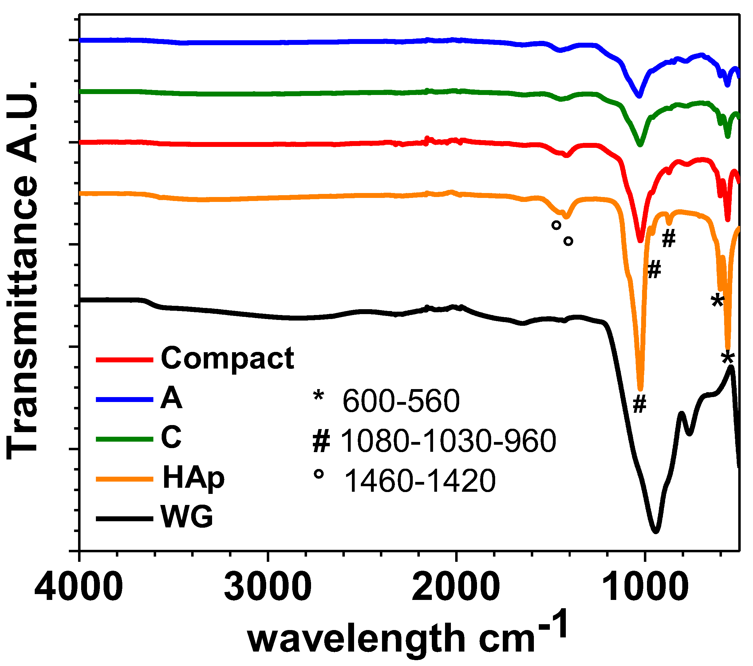
Figure 10.
Fluorescence microscopy images according to Live/Dead assay of hFOB cells after 1 day on COMPACT (A), A (B) and C (C) scaffolds. Calcein stains live cells in green, Ethidium homodimer-1 stains dead cells in red. Scale bars 100 μm.
Figure 10.
Fluorescence microscopy images according to Live/Dead assay of hFOB cells after 1 day on COMPACT (A), A (B) and C (C) scaffolds. Calcein stains live cells in green, Ethidium homodimer-1 stains dead cells in red. Scale bars 100 μm.
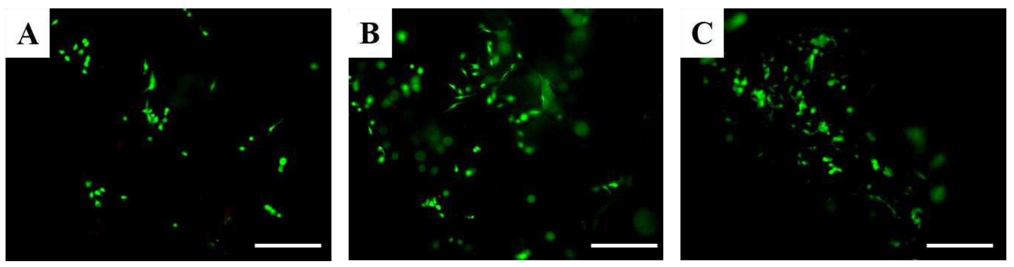
Figure 11.
PrestoBlue assay of hFOB cells on scaffolds at different timeframes equal to 1 and 3 days. ns p-value > 0.05; * p-value < 0.05.
Figure 11.
PrestoBlue assay of hFOB cells on scaffolds at different timeframes equal to 1 and 3 days. ns p-value > 0.05; * p-value < 0.05.
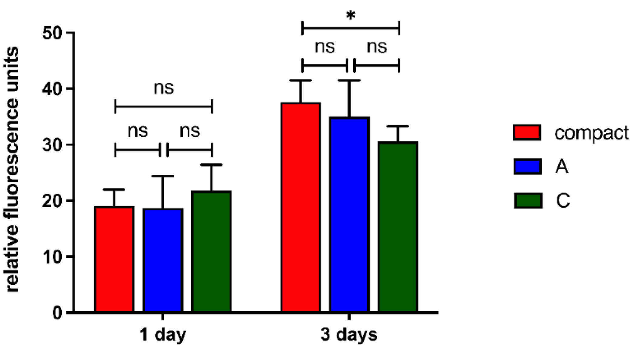
Figure 12.
Fluorescence analyses of hFOB cells after 3 days on scaffolds. Cell nuclei in blue (DAPI) and F-actin filaments in red (Phalloidin) are reported. Scale bars: 500 μm in left panels, 200 μm in central panels, and 50 μm in right panels.
Figure 12.
Fluorescence analyses of hFOB cells after 3 days on scaffolds. Cell nuclei in blue (DAPI) and F-actin filaments in red (Phalloidin) are reported. Scale bars: 500 μm in left panels, 200 μm in central panels, and 50 μm in right panels.
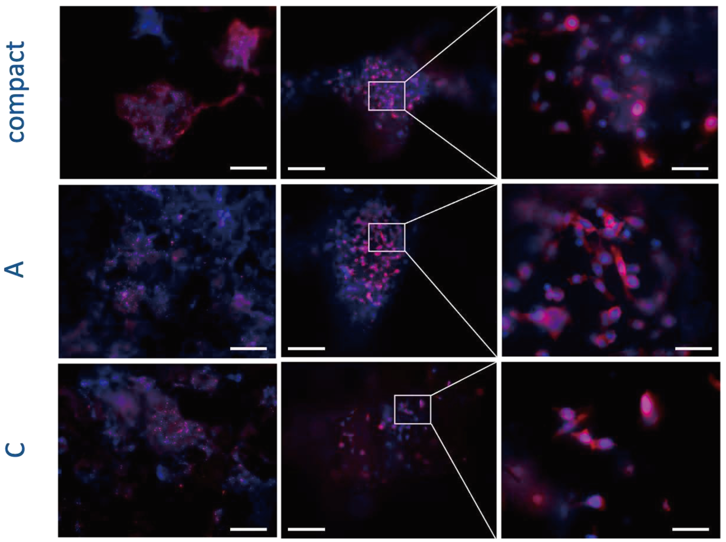

Table 1.
Composition of the samples * Lowest possible content to obtain a homogeneous paste.
| WG (ml) |
HAp (g) |
SiO2 (g) |
NaHCO3 (g) |
Density (g/cm3) | |
|---|---|---|---|---|---|
| COMPACT (1:1:0) | 5 * | 5 | - | - | 0.6 |
| A (3:1:1) | 16 | 5 | 6 | 1 | 0.5 |
| C (3:1:0) | 16 | 5 | - | - | 0.4 |
| D (1:0:1) | 5 | 5 | 0.3 | ||
| E (1:0:2) | 5 | 10 | 0.5 | ||
| F (1:1:1) | 5 | 5 | 5 | 0.5 | |
| G (1:0:0) | 5 | 0.2 |
Note that the samples D, E F and G were prepared/investigated to test the manufacturing process and to study density and mechanical properties of the materials in exam. They were excluded from the biological characterization due to their composition that we already know was not suitable for invivo test.
Disclaimer/Publisher’s Note: The statements, opinions and data contained in all publications are solely those of the individual author(s) and contributor(s) and not of MDPI and/or the editor(s). MDPI and/or the editor(s) disclaim responsibility for any injury to people or property resulting from any ideas, methods, instructions or products referred to in the content. |
© 2023 by the authors. Licensee MDPI, Basel, Switzerland. This article is an open access article distributed under the terms and conditions of the Creative Commons Attribution (CC BY) license (http://creativecommons.org/licenses/by/4.0/).
Copyright: This open access article is published under a Creative Commons CC BY 4.0 license, which permit the free download, distribution, and reuse, provided that the author and preprint are cited in any reuse.


